Article

The Effect of Spool Displacement Control to the Flow Rate in the Piezoelectric Stack-Based Valve System Subjected to High Operating Temperature

1
Department of Mechanical Engineering, Inha University, Incheon 22212, Korea
2
Department of Mechanical Engineering, The State University of New York, Korea (SUNY Korea), Incheon 21985, Korea
*
Authors to whom correspondence should be addressed.
Submission received: 29 July 2021 / Revised: 9 September 2021 / Accepted: 10 September 2021 / Published: 14 September 2021
(This article belongs to the Section Actuator Materials)

Abstract

:
This work investigates the effect of spool displacement control of the piezoelectric stack actuator (PSA) based valve system on the flow motion of the pressure drop and flow rate. As a first step, the governing equations of the structural parts of the displacement amplifier and spool are derived, followed by the governing equation of the fluid part considering control volume and steady flow force. Then, an appropriate size of the valve is designed and manufactured. An experimental apparatus to control the spool displacement is set up in the heat chamber and tracking control for the spool displacement is evaluated at 20 °C and 100 °C by implementing a proportional-integral-derivative (PID) feedback controller. The tracking controls of the spool displacement associated with the sinusoidal and triangular trajectories are realized at 20 °C and 100 °C. It is demonstrated that the tracking controls for the sinusoidal and triangular trajectories have been well carried out showing the tracking error less than 3 μm at both temperatures. In addition, the flow motions for the pressure drop and the flow rate of the proposed valve system are experimentally investigated. It is identified from this investigation that both pressure drop and flow rate evaluated 20 °C have been decreased up to 18% at 100 °C. This result directly indicates that the temperature effect to control performance of the structural part and fluid part in the proposed PSA based valve system is different and hence careful attention is required to achieve the successful development of advanced valve systems subjected to a wide range of the operating temperature.

1. Introduction

It is well known that piezoelectric actuators convert an electrical signal into physical displacement and vice versa, and hence can be used as an actuator or sensor. As an actuator, it is classified into either a bending actuator or a stack actuator. A thin layer of piezoelectric ceramic is bonded with beam-like flexible structures to make a relatively large deflection in the bending actuator. However, the available actuating force is small [1]. Thus, the bending actuator is widely used for active vibration control of flexible structures such as flexible robot arms instead of force or pressure control of dynamic systems. The stack actuator is made by stacking piezoelectric ceramic layers and electrode foils together with an adhesive. Since the ceramic layers are electrically connected in parallel and mechanically connected in series, the stack actuator can generate a much higher force than the bending actuator. However, the voltage-dependent displacement of the stack actuator is relatively small compared to the bending actuator. In general, when the stack actuator is used for several applications such as micro/nano positioning control and flow control of valve/pump systems, the displacement amplifier is absolutely required [2,3,4,5]. Significantly to successfully develop the valve system, both high actuating force and large displacement need to be met to achieve sufficient pressure drop or flow rate in a fast manner. This directly indicates that an appropriate displacement amplifier is required when the stack actuator is applied to the valve or pump system [6,7]. Advantages of the piezo stack-based direct valve system over conventional servo valves include low energy consumption, intrinsic safety for hardware protection, wide operating bandwidth, easy miniaturization, and anti-magnetic properties. Therefore, various types of the piezo stack-based valves have been and are being developed for diverse applications: flow control with constant flow rate, movement of fragile workpieces with the jerk-free motion, adhesive jetting dispenser in the semiconductor packaging process, accurate polishing of semiconductor wafers, medical areas such as cataract surgery, and various inflatable pillows for ride comfort.
Due to their advantages and wide application, many studies have been conducted on valve and pump systems integrated with piezo actuators. Some of the recent works related to this current work are surveyed as follows. A direct drive valve system driven by the piezo stack actuator was devised to achieve high operating frequency as well as more compactness of the valve system compared to conventional valves such as solenoid type [8,9]. A new type of liquid dispensing system integrated with the piezoelectric valve was developed to miniaturize the valve assembly and maximize the dispensing rate with high accuracy [10,11]. A nozzle-flapper valve driven by the piezo stack actuator was introduced to accurately control both the pressure and flow rate. The sliding mode control was adopted to evaluate the steady and unsteady pressure under the isothermal chamber [12]. A nonlinear model and sliding mode control of the hydraulic engine valve regulated by an innovative piezo-hydraulic valve spool were studied. A combination of the open-loop and closed-loop controller was implemented to accurately track desired trajectories for the engine valve position [13]. A piezoelectric actuator using a hydraulic displacement amplification mechanism considering the hysteresis of the actuator itself has been developed for the precise operation of large strokes [14]. It has been found that the positioning accuracy of piezoelectric transducers is limited by nonlinearities such as hysteresis and creep. Two piezoelectric transducers of the same type were used to operate linearly without a sensor to improve accuracy through feedback control. The relationship between nonlinear voltage and displacement was analyzed to reduce the position error due to nonlinearity [15]. Three piezoelectric microfluidic devices of diaphragm, normally closed valve, and normally open valve were proposed to meet some requirements for medical devices such as small size, safety, hermetic sealing, energy efficiency, and artifact-free medical imaging [16]. A piezoelectric micro-valve was proposed for the application of a drug delivery system in which the small axial displacement of the actuator was converted into a large stroke of the valve stopper based on hydraulic amplification [17]. A piezoelectric-driven microgripper with a three-stage amplification function to detect tip displacement and gripping force was proposed. The tip displacement and gripping force tracking experiment was performed with a PID controller [18]. A low-power, normally open piezoelectric microvalve was developed to replace conventional microvalve based on the polydimethylsiloxane featured by large peripheral connections that could decrease portability [19]. The hysteresis effect of the piezoelectric actuator to the flow control accuracy of a novel spool valve driven by a multi-layer piezoelectric ring bender was investigated wherein the comparison was made between the hysteretic compensator implemented as a feed-forward controller, while PID controller as a feedback controller [20]. To supplement control algorithm for simultaneous displacement and force self-sensing using a single piezoelectric stack actuator, the hysteresis was experimentally verified under various displacement and force conditions using the standard Prandtl–Ishlinskii hysteresis operator [21]. A piezo stack-based valve to resolve drawbacks of the hydraulic buck converter causing undesirable fluctuating forces was proposed where an active noise control technique using Filtered-X mean square algorithm was adopted to attenuate unwanted cancellate noises [22]. A simple inertial pump consisting of a cantilevered beam with the piezoelectric actuator and bionic valve made of silicone was proposed for the possible application to a heart valve with small flow resistance and large flow area [23]. The energy consumption of a four-way digital piezo stack-based valve was studied and demonstrated that a huge reduction of the electrical energy consumption during motion of switching and holding was achieved compared to other hydraulic on/off valves [24]. Using an asymmetric flexural hinge mechanism to which an asymmetric triangular displacement amplification mechanism is applied, the lateral displacement was increased, and the output speed of the piezoelectric actuator at low frequencies was significantly improved [25].
As evident from the previous works, there are many works on the control performance of the PSA-based valve systems (PSAVS in short) evaluated at room temperature and up to 60 °C. However, in real world there are many applications of the PSAVs to be operated at high temperatures. These applications include small hydraulic brake systems, automotive engine cooling system, fuel injector system and fin control valve system of the missile launch. Thus, many works on the properties of the piezoelectric actuators have been undertaken considering the temperature range from 20 °C to 180 °C [26]. In addition, it should be noted here that the PSAVS consists of two parts, namely a structural part and fluid part. The structural part includes the actuator itself, displacement amplifier, and spool, while the fluid part includes the operating oil or air. It is known that the structural parts are not sensitive to the operating temperature and hence control performance is favorable in a wide range of the temperature. However, the flow motion of the operating media (oil, air, adhesive, etc.) is easily changed due to the temperature-dependent viscosity and density. This may lead to undesirable results of the flow motions such as pressure drop and flow rate. In other words, even if the spool displacement of the PSAVS directly related to the flow motions is well controlled, the performance of the fluid motion cannot be satisfied. Despite the significance of this issue in the development of advanced PSAVA, there have been no reports of this problem so far.
It is noted here that Ohuchi et al. [27] first reported the multilayer piezo-actuator application for the spool displacement control in oil-pressure servo valves in 1985. The research undertaken in this work is the comprehensive follow up of this design to optimize the design for practical applications and investigate the effect of the spool displacement control to the flow rate. More specifically, the technical contribution of this work is to validate the different performance of the structural part (spool displacement) and fluid part (flow rate) of the PSAVS at high temperature. In order to achieve this goal, a compact size of the PSAVS is proposed and modeled using the integrated governing equations with the hinge-lever amplification mechanism, the spool-sleeve structure and flow motion. Then, a protype of the PSAVS is manufactured based on the model. Subsequently, to validate control performance of the structural part at 20 °C and 100 °C, the tracking control performance of the spool displacement is investigated using the proportional-integral-derivative (PID) controller. It is shown through the simulation and experiment that the tracking control of the spool displacement has been well carried out at both temperatures, showing a tracking error less than 3 μm. Subsequently, the flow motions of the pressure drop and flow rate the PSAVS are investigated at two different temperatures. It is identified from this investigation that both the pressure drop and flow rate evaluated at 100 °C are lower than those at 20 °C even though the spool displacement has been well controlled at both temperatures.

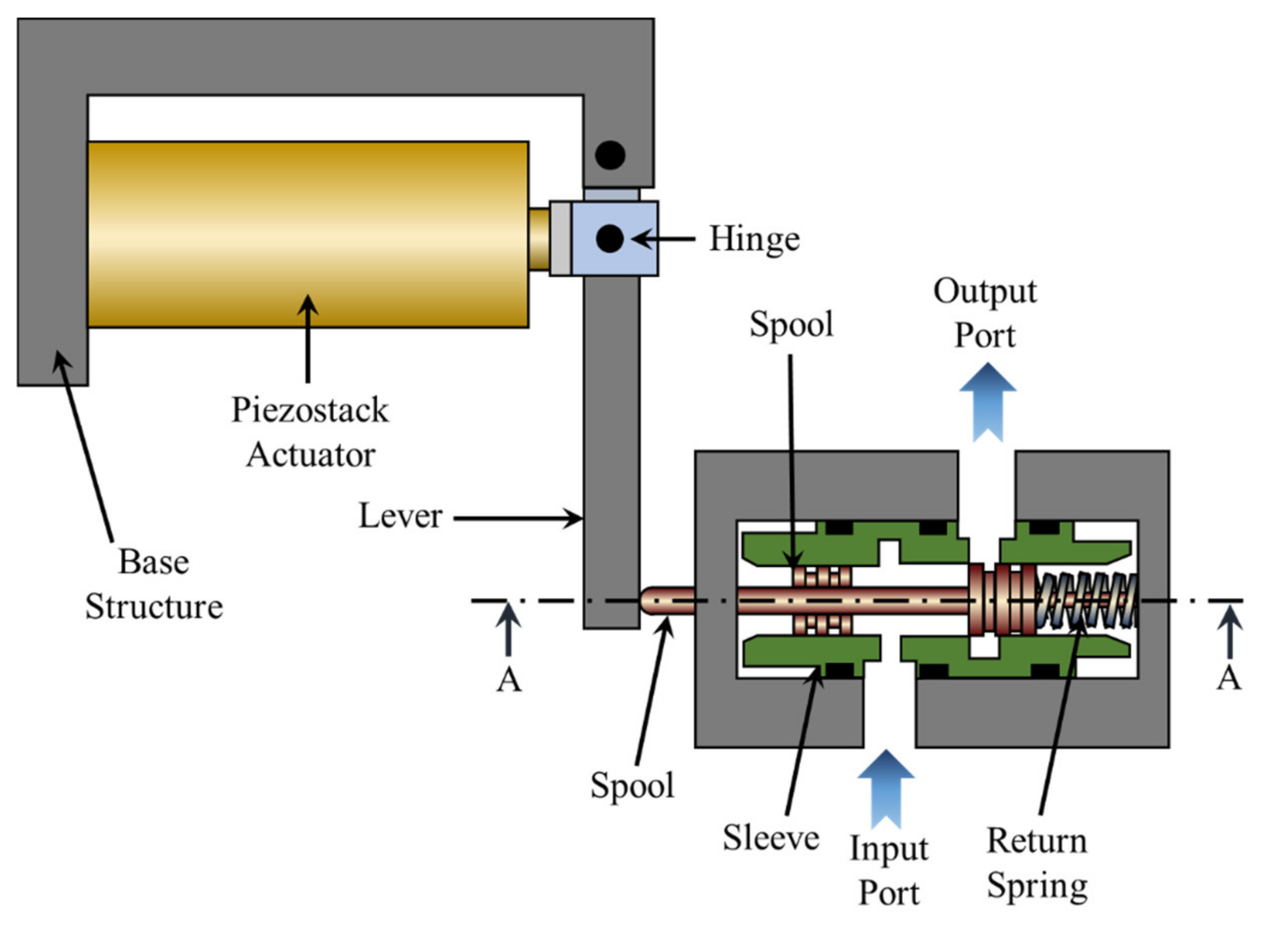
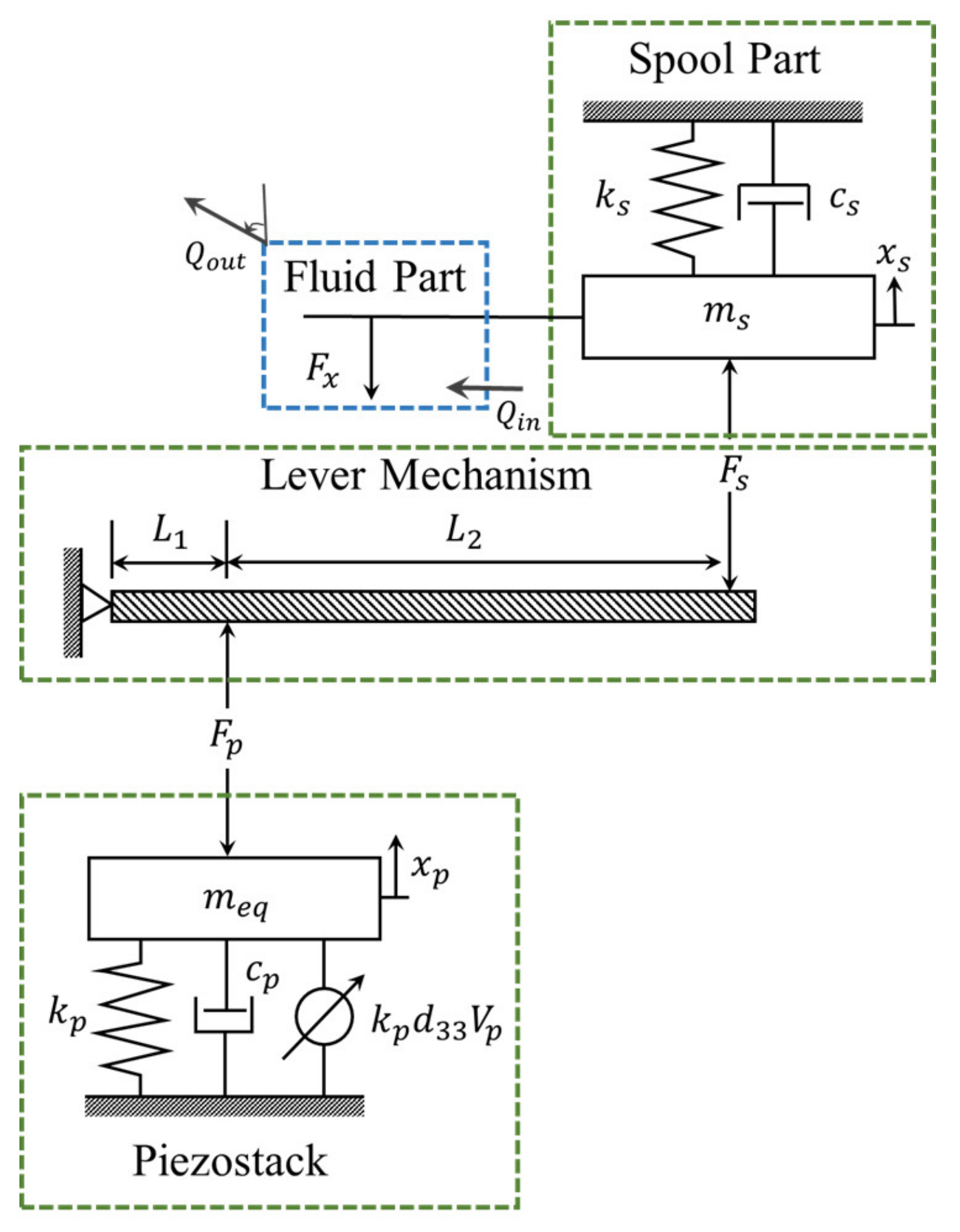
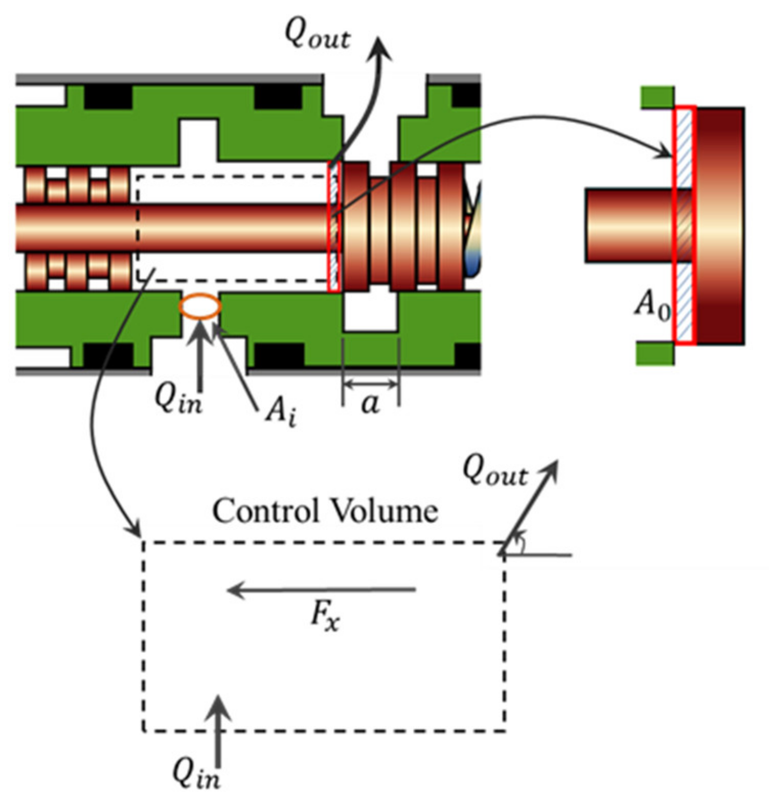
2. Modeling of Valve System

The schematic configuration of the proposed valve system is shown in Figure 1. This valve system is mainly composed of three parts, namely a PSA, lever mechanism, and spool. The PSA is the driving part that converts electrical energy into mechanical energy using the principle of the converse piezoelectric effect. This acts as an actuator that rotates the lever connected to the hinge counterclockwise. Since the stroke of the PSA is not sufficient to operate the proposed valve system, an additional mechanism is devised. The lever mechanism amplifies the displacement generated by the piezo actuator. Specifically, the lever mechanism fixes the base structure and the piezo stack actuator with the hinge and contacts the spool system to amplify the displacement. The displacement of the spool is then measured using a laser sensor. The piezoelectric stack can create a stroke proportional to the input voltage. Therefore, the position of the spool is proportional to the input voltage applied to the PSA. As a result, if a certain voltage is applied to the actuator, the PSA lengthens, and the lever rotates counterclockwise. As the spool moves to the right, the return spring is deformed by the PSA. On the other hand, if the input voltage is reduced, the force generated by the PSA is proportionally reduced, and hence the restoring force is generated under the influence of the return spring. Then, the spool returns to its original position. When the input voltage becomes zero, the spool is placed at the initial position. Consequently, according to this working principle, the PSA can continuously control the spool position by applying the input voltage.
The proposed PSAVS is a multi-physics system that is composed of the mechanical part and the fluid part. In this study, after obtaining each dynamic behavior of the PSA, lever mechanism and spool system, the governing equations for the mechanical part of the PSAV system are obtained using the dynamic equations of each mechanical part. Also, the flow force is considered in the fluid part. The governing equations of the entire PSAV system consist of the governing equations of the mechanical part and the fluid part. Figure 2 shows the mechanical model of the proposed valve system. The dynamic equation of the PSA actuator can be obtained as follows:
m e q x ¨ p + c p x ˙ p + k p x p = k p d 33 V p F p
where, m e q ,   c p ,   k p and d 33 is the effective mass, damping coefficient, stiffness of the piezostack actuator, and the free stroke of the piezo stack owing to a unit of the input voltage, respectively. The variables of x p and F p are the stroke of the tip point of the actuator and the force acting on the lever mechanism from the PSA. V p is the input voltage of piezostack actuator. The effective mass ( m e q ) of the piezostack can be calculated as follows [28].
m e q = m p 3 + m s l
In the above, m s l is the mass of the displacement-out slider, and m p is the mass of the piezoelectric materials, which can be obtained by:
m p = ρ p A p l p
where, l p ,   A p and   ρ p is the length of the piezoelectric stacks, the section area of the piezoelectric ceramics, and the density of the piezoelectric ceramic, respectively. In the lever mechanism, since the stiffness of the lever is high enough, the bending of the lever can be neglected. Then, the relationship between the stroke of the PSA and spool rod can be obtained by:
x p = L 1 L 1 + L 2 x s
where, L 1 is the length between the tip point of piezostack and the hinge which connects the lever and the base structure, and L 2 is the length between the tip point of the piezostack and the contacting part between the lever and spool rod. Using Newton’s second law of motion, the mathematical model of the lever is obtained as follows:
L 1 F p L 1 + L 2 F s = I L α a n g
In the above, I L and α a n g is the moment of inertia of the lever and angular acceleration of the lever, respectively. The moment of inertia of the lever can be obtained as follows:
I L = 1 12 m L ( ( L 1 + L 2 ) 2 + L H 2 )
where, m L and L H are the mass and the height of the lever. The mass of the lever can be calculated as:
m L = ρ L A L L 1 L 2
where, ρ L and A L is the density and the section area of the lever, respectively.
In this work, since the displacement of the spool is much smaller than the size of the lever, it is assumed that the α a n g is considered as x ¨ s / L 1 + L 2 . Then, Equation (5) can be rewritten as follows:
F s = L 1 L 1 + L 2 F p I L ( L 1 + L 2 )   2 x ¨ s
where, x s and F s is the displacement of the spool and the force acting on the spool part, respectively. The transmitted force ( F s ) by the lever mechanism pushes the spool rod and makes the displacement of the spool. The dynamic model of the spool can be mathematically obtained by:
m s x ¨ s + c s x ˙ s + k s x s = F s F x
where, m s , k s , and c s are the effective mass of the spool rod and spool, the stiffness of the return spring, and the damping coefficient from the frictional force. F x is the flow force. Now, from Equation (1), Equation (4), Equation (8) and Equation (9), the governing equation of the structural part of the PSAV system is determined by:
m s + m e q L 1 L 1 + L 2 2 + I L L 1 + L 2 2 x s ¨ + c s + c p L 1 L 1 + L 2 2 x s ˙ + k s + k p L 1 L 1 + L 2 2 x s = L 1 L 1 + L 2 k p d 33 V p t F x
In the fluid part, in order to calculate the flow force, several assumptions are made: (i) the valve is an overlapping type; (ii) the leakage though the radial clearance is neglected; and (iii) the throttle area is proportional to the valve opening. Although the overlapping-type valve has nonlinearity in the overlapping range, this type has small internal leakage and can easily be realized in practice. Figure 3 shows the schematic diagram of the control volume of the spool valve. The fluid enters to the control volume through the inlet area, A i and exits the control volume through the outlet area, A 0 , respectively. The outlet area ( A 0 ) of the valve can be calculated as follows:
x s < ε : A 0 = 0 ε < x s < ε + a : A 0 = 2 × D s × sin 1 H s D s × x s ε x ε + a : A 0 = 2 × D s × sin 1 H s D s × a
where, D s is the diameter of the spool. a and H s are the width and height of the outlet port. ε is the length of the overlap. Then the flow rate (Q) can be calculated using the orifice equation as follows:
Q = C d A 0 2 Δ P ρ
where, C d is the discharge coefficient. ρ and Δ P is the density of the fluid and pressure drop, respectively. The discharge coefficient, which is the value from 0.6 to 0.65 is a function of Reynolds number and cavitation number [29].
The conservation of the fluid momentum can be obtained from the Reynolds transport theorem as follows [30]:
F =   t c v ρ u   d V + c s ρ u u · n ^ d A
where, u and n ^ are the fluid velocity vector and the unit vector which directs normally outward direction from the control volume surface. F is the flow force vector which is combination of the vertical direction force and axial direction force. Since the frictional force affected by the vertical direction force is already reflected in Equation (9), the vertical direction force is not considered as a flow force in this work.
Now, the flow force is obtained using the following equation.
F x = ρ L Q t ρ Q 2 A 0 cos θ
where, L is the length between the outlet port and inlet port and θ is the jet angle. Equation (14) can be rewritten by considering the transient flow force F t r which is related to the gradient of the flow rate and steady flow force F s t , which is related to the square of flow rate as follows:
F x = F t r F s t F t s = ρ L Q t ,       F s t = ρ Q 2 A 0 cos θ
Substituting Equations (11) and (12) to Equation (15), the transient and steady flow force can be rewritten as follows by considering the shape of the proposed spool valve.
x s < ε                     : F t r = 0 , F s t = 0 ε < x s < ε + a                     : F t r = 2 L C d D s sin 1 H s D s 2 ρ Δ P x ˙ s + A 0 L C d ρ 2 Δ P Δ P ˙                           F s t = 4 D s x s ε Δ P C d 2 cos θ sin 1 H s D s x s ε + a                     : F t r = 0 , F s t = 4 D s a Δ P C d 2 cos θ sin 1 H s D s
Then, the governing equation of the proposed PSAVS can be formulated from the governing equation of the mechanical part (Equation (10)) and the fluid part (Equations (15) and (16)) as follows. There are two state variables: x s and Δ P , where x s is mechanical variable and Δ P is fluid dynamic state variable.
x s < ε                             : m s + m e q L s L 1 2 + L L 2 x ¨ s + c s + c p L s L 1 2 x ˙ s                             + k s + k p L s L 1 2 x s = L s L 1 k p d 33 V p t ,   ε < x s < ε + a                             : m s + m e q L s L 1 2 + L s 2 I L x ¨ s                             + c s + c p L s L 1 2 + 2 L C d D s sin 1 H s D s 2 ρ Δ P x ˙ s                             + k s + k p L s L 1 2 + 4 D s Δ P C d 2 cos θ sin 1 H s D s x s                             + A 0 L C d ρ 2 Δ P Δ P ˙ 4 D s ε Δ P C d 2 cos θ sin 1 H s D s = L s L 1 k p d 33 V p t x s ε + a                             : m s + m e q L s L 1 2 + L L 2 I L x ¨ s + c s + c p L s L 1 2 x ˙ s                             + k s + k p L s L 1 2 x s 4 D s a Δ P C d 2 cos θ sin 1 H s D s = L s L 1 k p d 33 V p t
where L s is 1 / L 1 + L 2 .

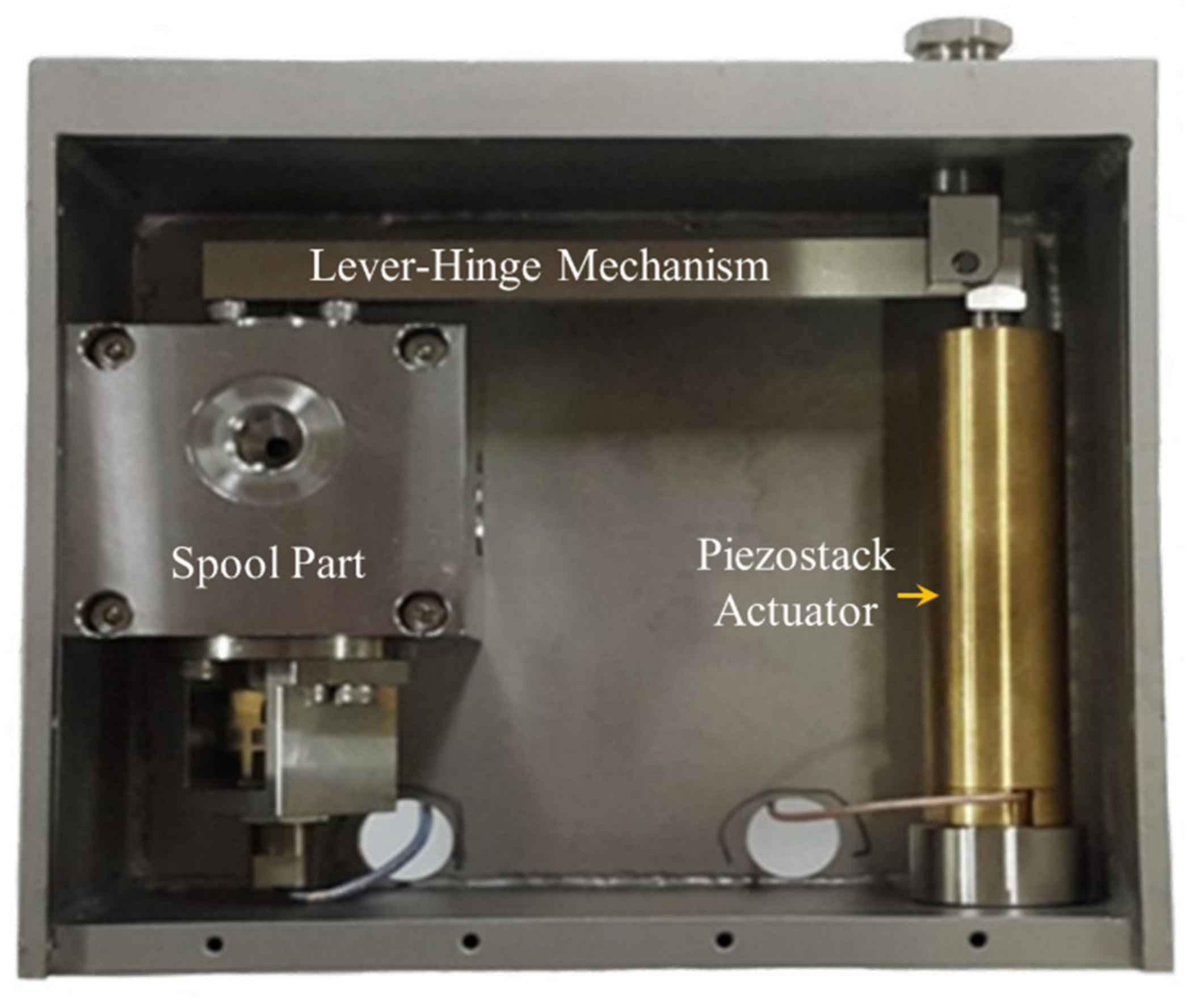
3. Design and Manufacturing of PSAVS

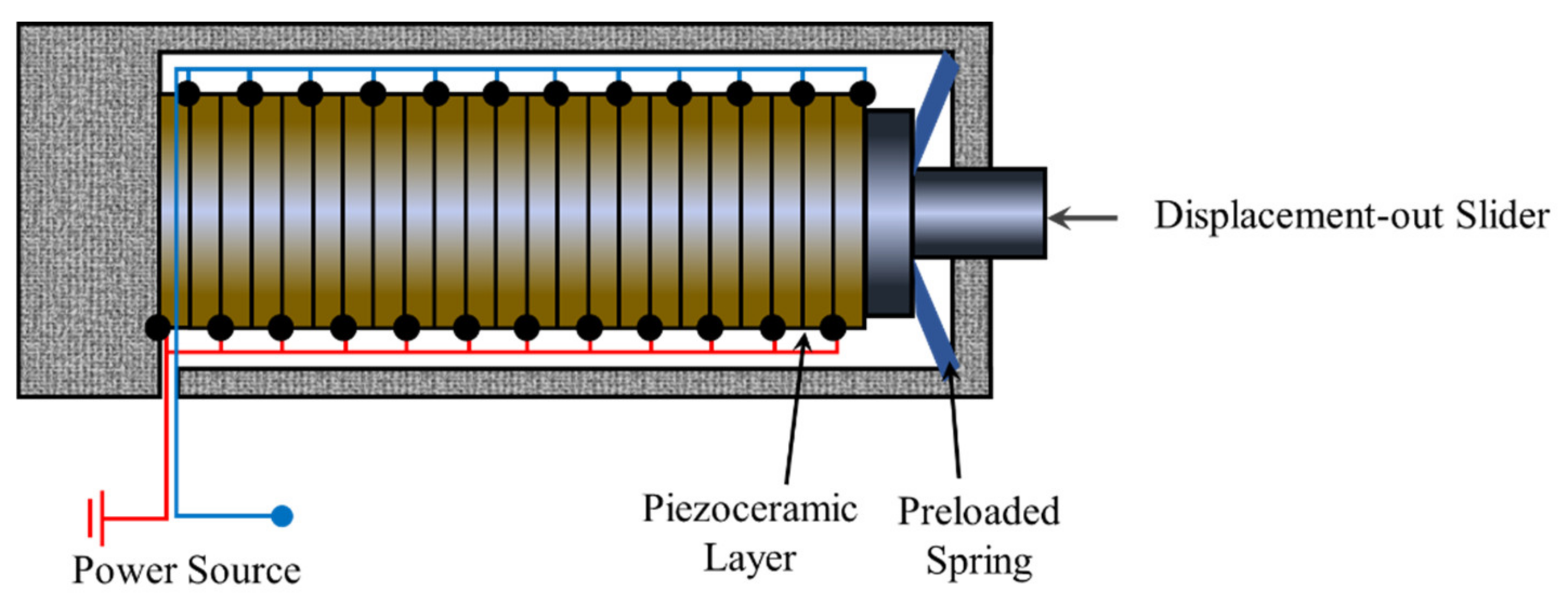
3.1. Piezostack Actuator

In this work, the stack-type piezoelectric actuator (Pst150hTc/20/100/VS25 model manufactured by PIEZOMECHANIK, München, 81673, Germany) shown in Figure 4 is used for operating the proposed PSAV system. The used PSA comprises ceramic layers that are mechanically linked in series and electrically linked in parallel. Thus, the PSA can produce large displacements in comparison with the conventional piezoceramic actuator. In addition, the PSA has advantages such as high generative force and fast response. However, since the PSA cannot endure the pulling force, the piezoceramic layers are preloaded by a preloaded spring in series to tolerate some pulling force in real applications. Thus, the PSA used in his work consists of the displacement-out slider, the preloaded spring and the stacked piezoceramic layers. The displacement of the piezoceramic layers is transferred by the displacement-out slider. Table 1 gives the design parameters of the PSA employed in this work. It should be noted that the damping coefficient of the piezo stack actuator was calculated by experimentally measuring the step response of the PSA. These parameters, of course, are to be used for the governing equations given by Equation (16). It should also be noted that the maximum operating temperature of the PSA is 90 °C, and hence, in this work, the control performance is evaluated at 20 °C and 100 °C to observe the different behavior.

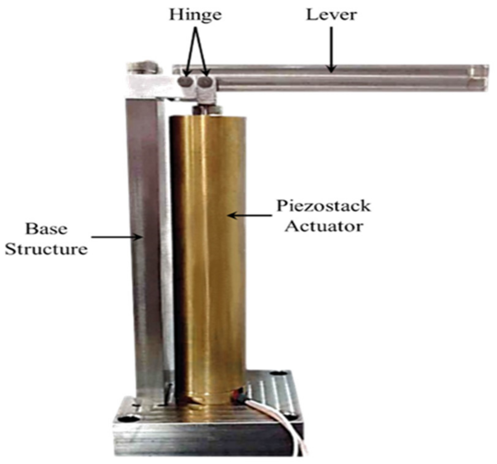
3.2. Lever Mechanism
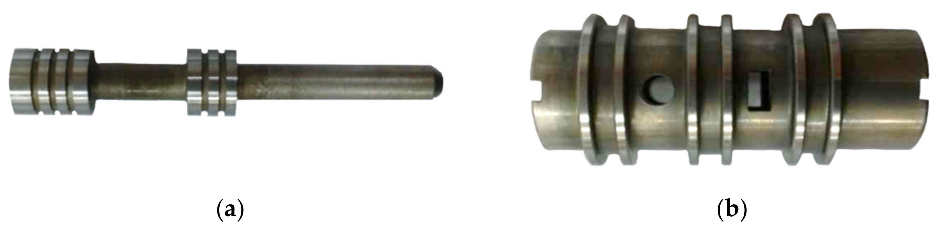
Although the PSA has many advantages, such as high-power density, high actuating force, and fast response, it has also demerits. One of the weak points is the limitation of the stroke in comparison with its size (generally, the piezo stack can be deformed maximum of 0.1% of the original dimension). In order to resolve the displacement restriction of the PSA, in this work, a lever mechanism is designed and constructed, as shown in Figure 5. The lever mechanism plays a couple of important roles, including amplifying the displacement and transmitting the actuating force generated by the piezo stack actuator. Table 2 gives the design parameters of the lever mechanism. These parameters are used for the calculation of the governing equation given by Equation (17).

3.3. Spool Part

Figure 6a,b show the manufactured spool and sleeve part, respectively. To obtain the linear relationship between the spool displacement and an outlet flow rate, the shape of the output port is chosen by square. Table 3 shows the design parameters of the spool part. The damping coefficient of the spool was calculated by experimentally measuring the step response of the spool part. CFD simulation (ANSYS Fluent) was also performed to determine discharge coefficient and jet angle considering the flow behavior at the spool valve. In this study, assuming that the spool valve is sufficiently open, the values of the discharge coefficient and the injection angle are determined when the effective spool displacement is 0.7 mm. These parameters are to be used for the calculation of the governing equation of the proposed PSAVS given by Equation (17). Now, considering the schematic and model of the PSAVS shown in Figure 1 and Figure 2, three parts of the PSA, lever mechanism for displacement amplifier and spool are assembled as shown in Figure 7. The assembled PSAVS will be tested in a subsequent section to evaluate the tracking control of the spool displacement.

4. Control Performance

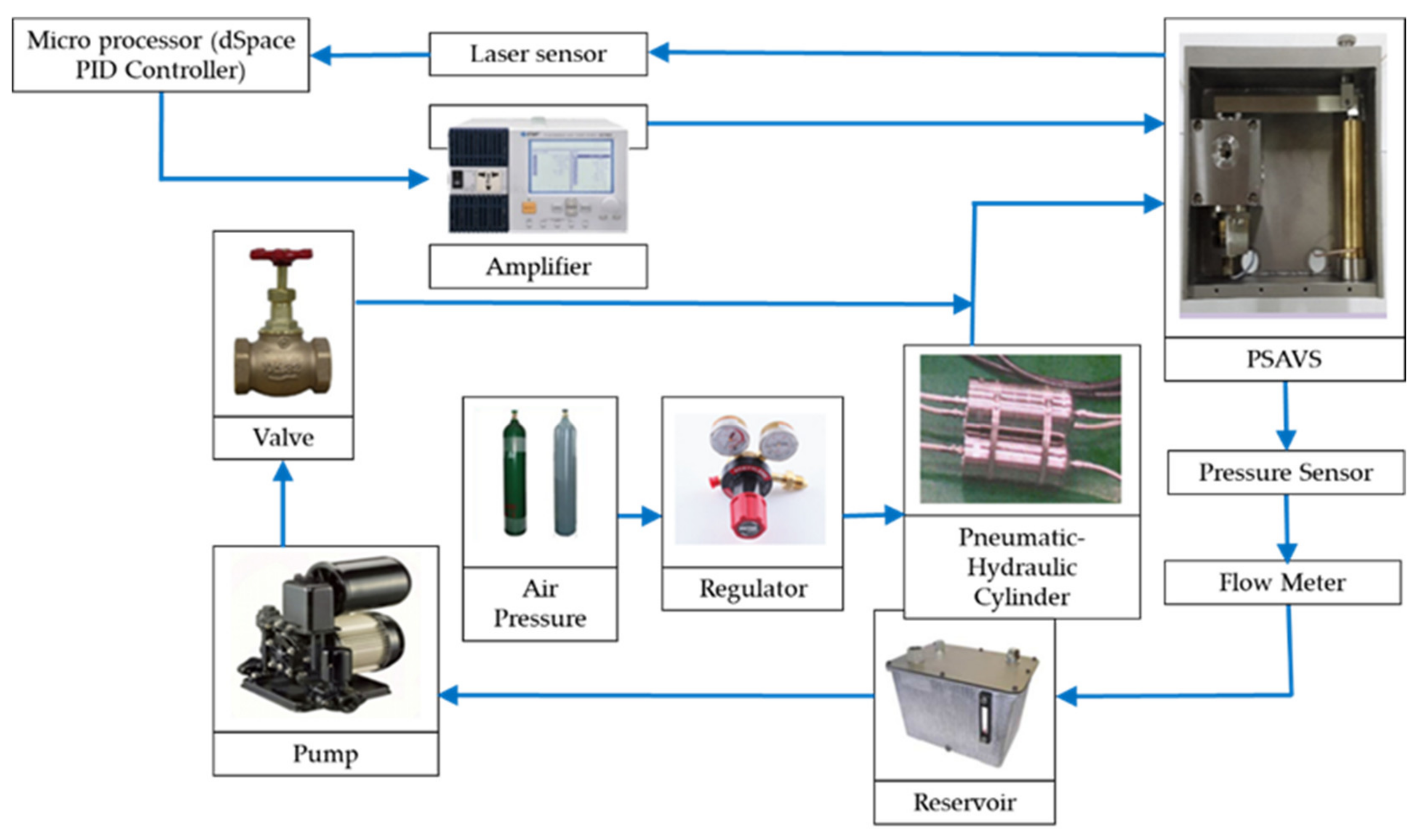
4.1. An Experimental Apparatus

Figure 8 presents a control block-diagram of the experimental apparatus for the tracking control of the spool displacement measured from the laser sensor. As shown in the figure, the pneumatic circuit part consists of the nitrogen tank, regulator, and pneumatic-hydraulic cylinders. Generally, the initial charging pressure of the commercial nitrogen tank is about 120~140 bar. The regulator regulates the output pressure of the nitrogen tank continuously. The pneumatic-hydraulic cylinder converts the pneumatic pressure into hydraulic pressure by adopting the piston-cylinder mechanism. To control the hydraulic oil temperature, the pneumatic, hydraulic cylinder is located inside the heating chamber. It is remarked here that even though the main issue of this work is to control the spool displacement, two pressure meters are set up to measure the pressure drop between the inlet and outlet ports of the PSAVS, while the flow meter is located to measure the flow rate at two different temperatures.

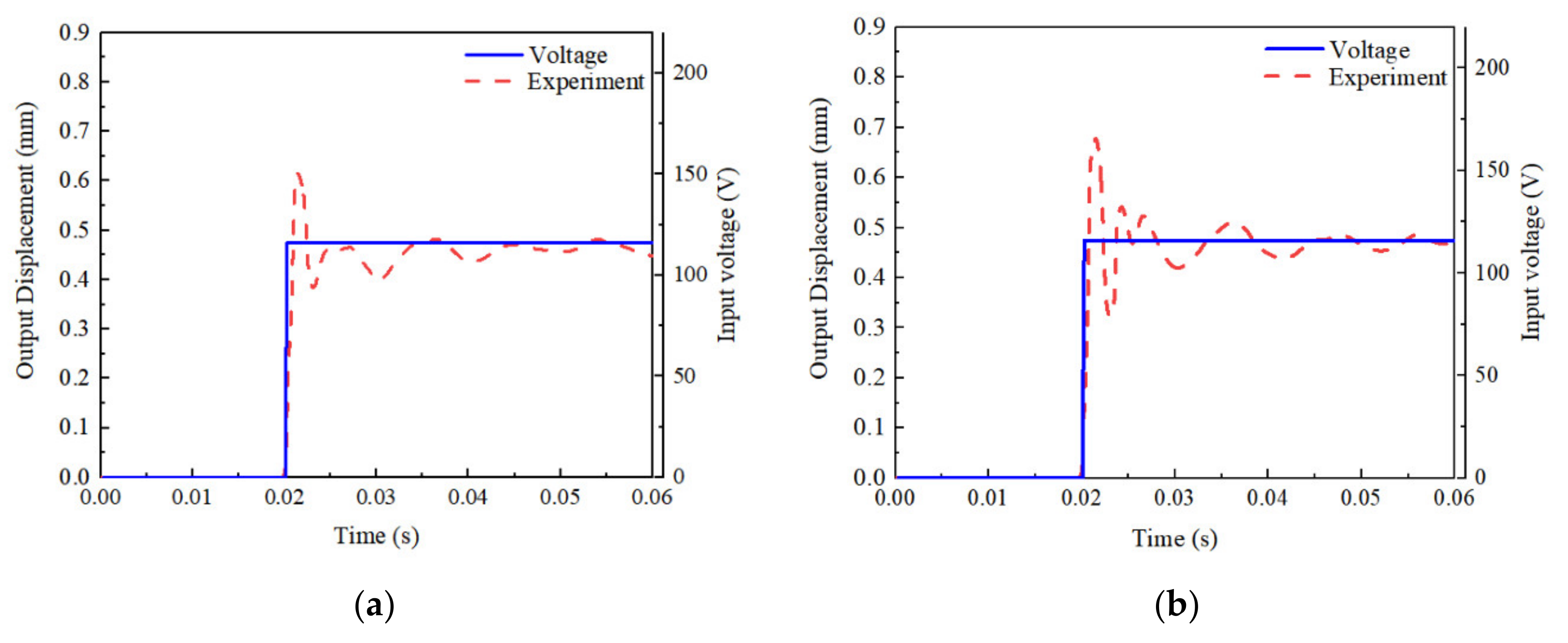
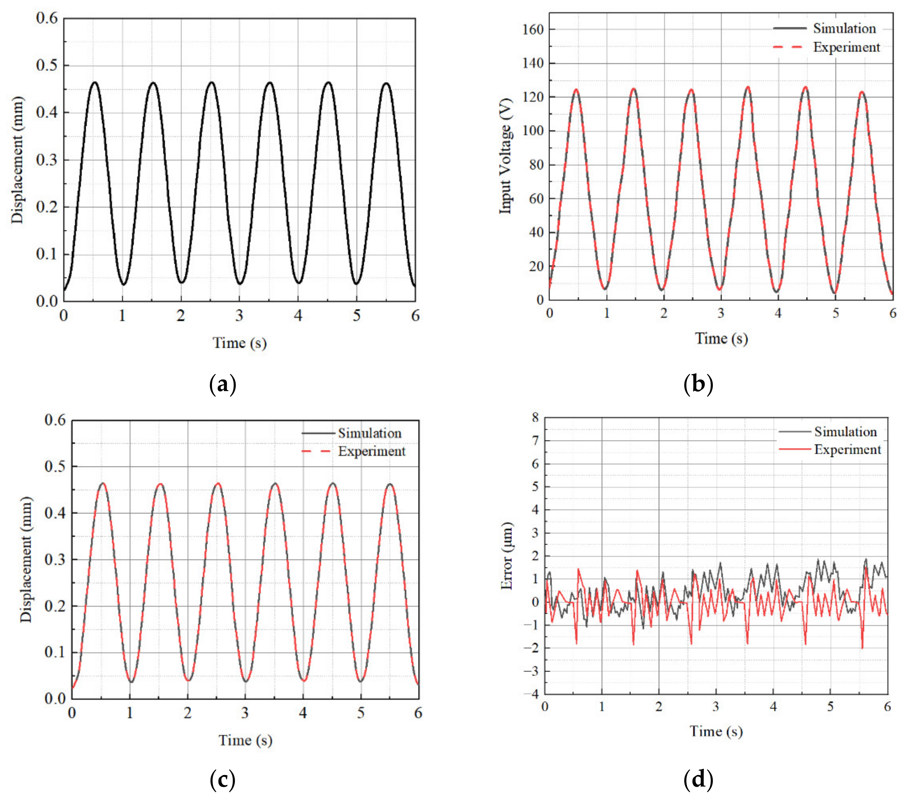
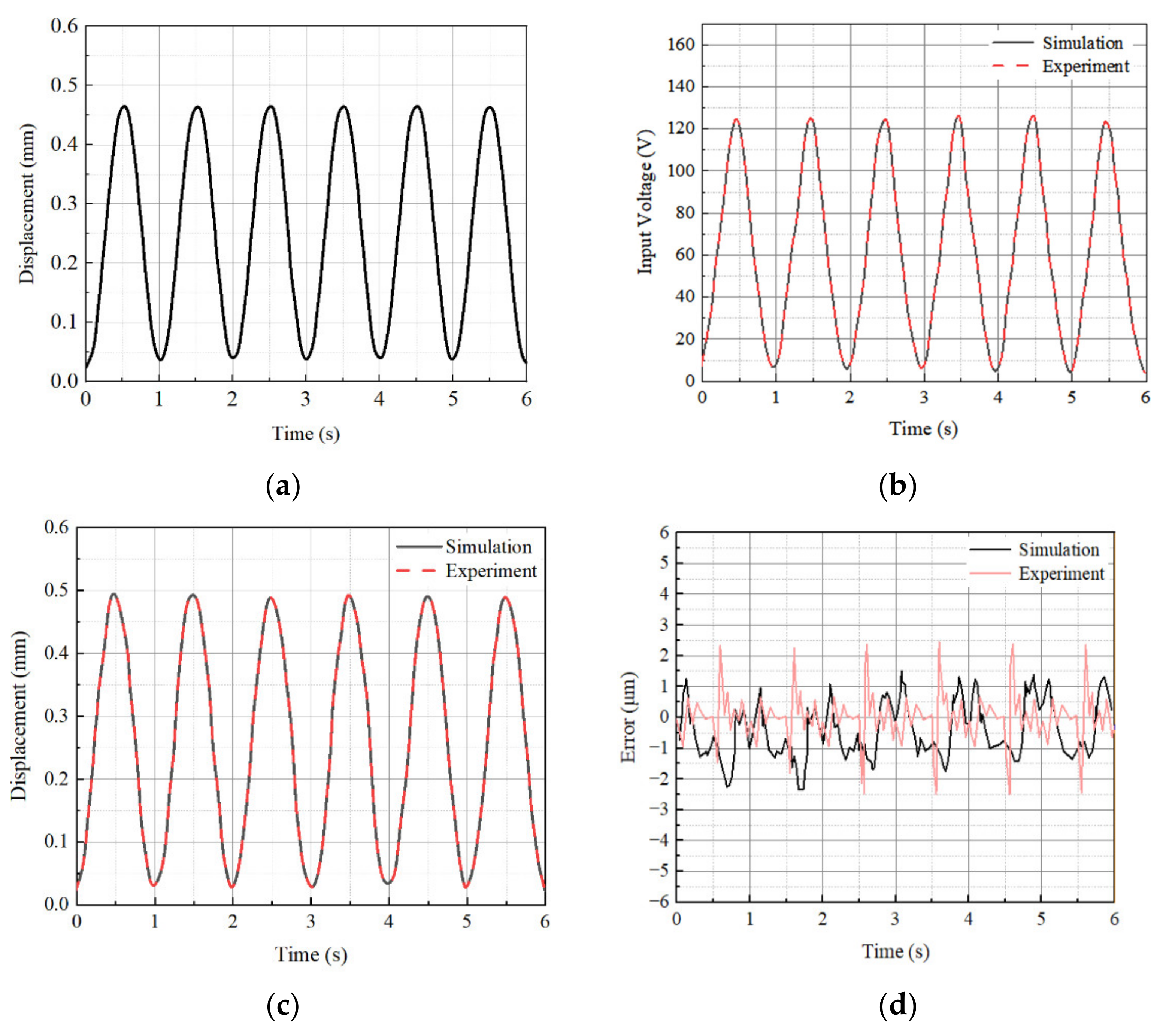
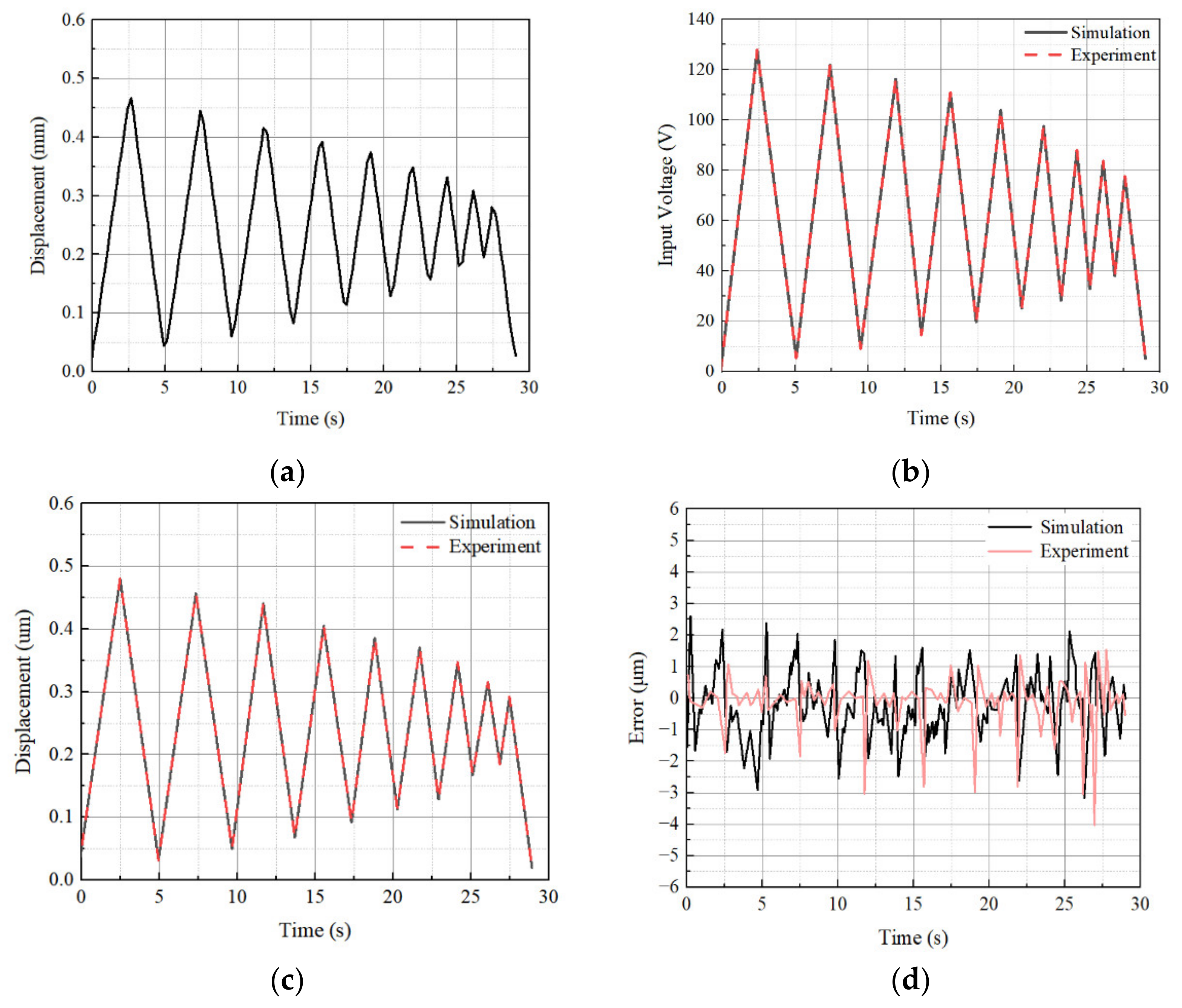
4.2. Spool Displacement Control

The time response is generally used for evaluating the transient characteristics of mechanical systems. To measure the time response, a step signal is generated, amplified and transferred to the PSA, and the output spool displacement is measured. In the experiment, the input pressure of 70 bar is supplied to the valve in the closed state. Figure 9 shows the step response to the step input voltage of 120 V. Figure 9a shows the result evaluated at 20 °C. From the experimental response, the response time, which indicates the time to reach about 63.2% of its steady state, can be identified as 0.65 ms. Figure 9b shows the step response of the spool at 100 °C from which the response time is identified as 0.7 ms. Thus, it is concluded that the response time of the spool to the step input voltage between a room and high temperatures is not much different. This directly indicates that the dynamic bandwidth of the PSAVS at room temperature is not degraded due to the high temperature. From this observation, a very similar tracking control performance of the spool displacement is expected between 20 °C and 100 °C for the same spool trajectories. It is briefly remarked here that the delayed time of 0.05 ms due to the high temperature is arisen from the reduced stiffness of the return spring.
In this work, a simple but practically effective PID controller is implemented for the tracking control of the spool displacement. The PID control input is determined by
u t   =   k p e t   +   k i 0 t e τ d τ + k d d d t e t    
In this above, e(t) is the error of displacement of the spool between desired and actual signals. k p , k i and k d are the proportional, integral, and derivative gain of PID controller, respectively. The k p , k i , and k d are determined using Ziegler–Nichols tuning method with each temperature condition. The determined values for 20 °C are 0.15, 85 and 0.01, respectively, while 0.25, 88, and 0.005, respectively, for 100 °C. Figure 10 and Figure 11 present the tracking control results of the sinusoidal spool displacement at 20 °C and 100 °C, respectively. The simulation was performed in MATLAB, and the dynamic equation was numerically solved using the Runge-Kutta method. It is clearly observed that the tracking performance for the spool displacement is good for both 20 °C and 100 °C, respectively, resulting in the tracking error of less than 3 μm. It is noted that the tracking error is defined as the difference between the desired displacement and output displacement. The tracking control performance is not degraded since the control gains of the PID controller are determined by considering the temperature effect to the step response representing the dynamic model of the spool system. A more complex trajectory than the sine trajectory is chosen as the next investigation, and the results are shown in Figure 12 and Figure 13. It is clearly shown that the spool tracks well to the time-varying triangular trajectory with a small tracking error for both 20 °C and 100 °C, respectively. It is identified that the tracking error for all cases is less than 3 μm, which is acceptable for precision control of the valve system. It should be remarked that the simulation result achieved from the governing equation is well agreed to the measured result in regards to the maximum bound of the tracking error. However, the error history (profile) of the simulation case with respect to the time is different from the experiment since the voltage-dependent hysteresis behavior of PSA, which is occurred in practice, is not considered in the governing equation derived in this work. The response time of the piezoelectric stack actuator itself is very fast up to 500 Hz, but the proposed system does not exhibit such as a fast response since there is delay due to the displacement amplifier and spool sleeve. Figure 14 shows the frequency response of the spool with excitation magnitude of ±0.15 mm. It is clearly seen that the control bandwidth is ranged up to 300 Hz. Subsequently, we carried out the tracking control up to 100 Hz at 100 °C as shown in Figure 15. It is observed that the tracking error is increased as the frequency reaches to 100 Hz.
In fact, in order to complete the performance evaluation of the PSAVS, the controllability of the flow rate needs to be carried out. To do so, the governing equation and controller design should be formulated in a manner of much different aspects from the current work, which has been focused on the tracking control of the spool displacement. Thus, the flow rate control will be completely undertaken as a second phase of this work in the near future. However, a couple of meaningful results measured from the current experimental apparatus are presented. For obtaining the controllable flow rate range and position range of the spool at relatively low frequency, the applied voltage on the actuator is set as V t   =   65 sin 0.2 π t   +   65 V . Figure 16 presents the measured pressure drop and flow rate at 20 °C and 100 °C by applying the set voltage. The pressure drop is the difference between the input and output ports. As shown in Figure 16, when the displacement of the spool is within 0 to 0.01 mm, the valve has zero flow rate. As early mentioned, this is due to the fact that the spool has 0.01 mm overlap length. It is clearly observed that both the pressure drop and flow rate are increased at high temperature. Especially, the maximum flow rate at room temperature identified as 13.5 LPM (liter per minute) is increased about 18.0% at high temperature. This is due to the fact that the viscosity and density of the operating oil are reduced at 100 °C. This directly indicates that to achieve accurate flow rate control, both design parameters and other temperature-dependent issues including oil should be considered in the formulation of the governing equation and controller design as well. From this preliminary investigation, it is fully understood that the tracking control of the spool displacement and flow rate control is a much different. It is remarked here that in this work the pressure of the pressurized hydraulic oil is measured by the pressure sensor (A-10, WIKAI Co., Gyeonggi-do 18103, Korea), while the flow rate is measured by the flow meter (TM0050X1/2, Turbines Co., Altus, OK 73523, USA), which has a slow response time. The step-like signal of the flow rate is caused for the slow response of the flow meter.

5. Conclusions

This work presented the effect of the operating temperature to control performance for the structural part and fluid part of the PSA-based valve system (PSAVS). The proposed valve system consists of the PSA, a lever mechanism for the displacement amplifier, and a spool part for the flow motion. After briefly discussing the working principle, the governing equations for the structural part and fluid part were derived followed by manufacturing a prototype. An experimental apparatus for the tracking control of the spool displacement was established in the heat chamber. Prior to undertaking the tracking control of the spool displacement, a Bode plot representing the magnitude with respect to the exciting frequency was experimentally obtained at 20 °C and 100 °C. Then, two different trajectories of the spool displacement (sinusoidal and triangular) were adopted to be tracked and tracking control performance was evaluated by implementing a PID controller. It is demonstrated through the simulation and experiment that the tracking control performances of the spool displacement has been well achieved showing the tracking error less than 3 μm at both temperatures. In addition, the pressure drop between the inlet and outlet ports, and the flow rate of the valve were experimentally investigated. It is identified from this investigation that the flow rate evaluated at 20 °C has been decreased up to 18.0% compared with that evaluated at 100 °C. The results presented in this work are self-explanatory stating that the fluid motion control needs to be carefully treated at high operating temperature even though control performance of the structural part is satisfied. It is remarked, finally, that the research on the control strategy for the fluid motions such as flow rate at high temperatures is to be undertaken as a second phase of this work in the future.

Author Contributions

Conceptualization, S.-B.C. and D.J.; methodology, S.-B.C. and J.-C.J.; software, Y.-J.P. and B.-G.K.; validation, J.-C.J. and Y.-J.P.; formal analysis, J.-C.J. and S.-B.C., investigation, B.-G.K. and Y.-J.P.; data curation, Y.-J.P.; writing—original draft preparation J.-C.J., Y.-J.P. and S.-B.C.; writing—review and editing, D.J. and S.-B.C.; visualization, D.J.; supervision, S.-B.C.; All authors have read and agreed to the published version of the manuscript.

Funding

This research received no external funding.

Institutional Review Board Statement

Not applicable.

Informed Consent Statement

Not applicable.

Data Availability Statement

The authors exclude this statement.

Conflicts of Interest

The authors declare no conflict of interest.

References

  1. Niezrecki, C.; Brei, D.; Balakrishnan, S.; Moskalik, A. Piezoelectric Actuation: State of the Art. Shock. Vib. Dig. 2001, 33, 269–280. [Google Scholar] [CrossRef]
  2. Kim, J.H.; Kim, S.H.; Kwak, Y.K. Development of a piezoelectric actuator using a three-dimensional bridge-type hinge mechanism. Rev. Sci. Instrum. 2003, 74, 2918–2924. [Google Scholar] [CrossRef]
  3. Juuti, J.; Kordás, K.; Lonnakko, R.; Moilanen, V.-P.; Leppävuori, S. Mechanically amplified large displacement piezoe-lectric actuators. Sens. Actuators A Phys. 2005, 120, 225–231. [Google Scholar] [CrossRef]
  4. Choi, S.; Han, S.; Lee, Y. Fine motion control of a moving stage using a piezoactuator associated with a displacement am-plifier. Smart Mater. Struct. 2004, 14, 222. [Google Scholar] [CrossRef]
  5. Nguyen, Q.-H.; Choi, S.-B.; Kim, J.-D. The design and control of a jetting dispenser for semiconductor electronic packaging driven by a piezostack and a flexible beam. Smart Mater. Struct. 2008, 17, 065028. [Google Scholar] [CrossRef]
  6. Lindler, J.E.; Anderson, E.H. Piezoelectric direct drive servovalve. In Proceedings of the Smart Structures and Materials 2002: Industrial and Commercial Applications of Smart Structures Technologies, San Diego, CA, USA, 9 July 2002; International Society for Optics and Photonics: Bellingham, WA, USA, 2002; pp. 488–496. [Google Scholar]
  7. Zhou, M.-L.; Yang, Z.-G.; Gao, W.; Tian, Y.-T.; Shen, C.-L.; Li, P. Fuzzy control of a new type of piezoelectric direct drive electro-hydraulic servo valve. In Proceedings of the 2005 International Conference on Machine Learning and Cybernetics, Guangzhou, China, 18–21 August 2005; Institute of Electrical and Electronics Engineers (IEEE): Piscataway, NJ, USA, 2005; Volume 2, pp. 819–824. [Google Scholar]
  8. Changbin, G.; Zongxia, J. A piezoelectric direct-drive servo valve with a novel multi-body contacting spool-driving mecha-nism: Design, modelling and experiment. Proc. Inst. Mech. Eng. Part C J. Mech. Eng. Sci. 2014, 228, 169–185. [Google Scholar] [CrossRef]
  9. Jeon, J.; Nguyen, Q.-H.; Han, Y.-M.; Choi, S.-B. Design and Evaluation of a Direct Drive Valve Actuated by Piezostack Actuator. Adv. Mech. Eng. 2013, 5, 986812. [Google Scholar] [CrossRef]
  10. Niles, W.D.; Coassin, P.J. Piezo- and Solenoid Valve-Based Liquid Dispensing for Miniaturized Assays. ASSAY Drug Dev. Technol. 2005, 3, 189–202. [Google Scholar] [CrossRef]
  11. Sun, J.; Ng, J.H.; Fuh, Y.H.; Wong, Y.S.; Loh, H.T.; Xu, Q. Comparison of micro-dispensing performance between micro-valve and piezoelectric printhead. Microsyst. Technol. 2009, 15, 1437–1448. [Google Scholar] [CrossRef]
  12. Kamali, M.; Jazayeri, S.A.; Najafi, F.; Kawashima, K.; Kagawa, T. Study on the performance and control of a pie-zo-actuated nozzle-flapper valve with an isothermal chamber. Stroj. Vestn. J. Mech. Eng. 2016, 62, 318–328. [Google Scholar] [CrossRef] [Green Version]
  13. Haus, B.; Aschemann, H.; Mercorelli, P.; Werner, N. Nonlinear modelling and sliding mode control of a pie-zo-hydraulic valve system. In Proceedings of the 2016 21st International Conference on Methods and Models in Automation and Robotics (MMAR), Miedzyzdroje, Poland, 29 August–1 September 2016; IEEE: Piscataway, NJ, USA, 2016; pp. 442–447. [Google Scholar]
  14. Mohith, S.; Rao, M.; Karanth, N.; Kulkarni, S.; Upadhya, A.R. Development and assessment of large stroke pie-zo-hydraulic actuator for micro positioning applications. Precis. Eng. 2021, 67, 324–338. [Google Scholar]
  15. Poik, M.; Kohl, D.; Schitter, G. Similarity-based Feedback Control for Linear Operation of Piezoelectric Actuators. In Proceedings of the 2018 IEEE/ASME International Conference on Advanced Intelligent Mechatronics (AIM), Auckland, New Zealand, 9–12 July 2018; Institute of Electrical and Electronics Engineers (IEEE): Piscataway, NJ, USA, 2018; pp. 97–102. [Google Scholar]
  16. Bußmann, A.B.; Durasiewicz, C.P.; Kibler, S.H.A.; Wald, C.K. Piezoelectric titanium based microfluidic pump and valves for implantable medical applications. Sens. Actuators A Phys. 2021, 323, 112649. [Google Scholar] [CrossRef]
  17. Goettsche, T.; Kohnle, J.; Willmann, M.; Ernst, H.; Spieth, S.; Tischler, R.; Messner, S.; Zengerle, R.; Sandmaier, H. Novel approaches to particle tolerant valves for use in drug delivery systems. Sens. Actuators A Phys. 2005, 118, 70–77. [Google Scholar] [CrossRef]
  18. Zhao, Y.; Huang, X.; Liu, Y.; Wang, G.; Hong, K. Design and Control of a Piezoelectric-Driven Microgripper Perceiving Displacement and Gripping Force. Micromachines 2020, 11, 121. [Google Scholar] [CrossRef] [PubMed] [Green Version]
  19. Jang, S.; Oh, J.H. Rapid Fabrication of Microporous BaTiO3/PDMS Nanocomposites for Triboelectric Nanogenerators through One-step Microwave Irradiation. Sci. Rep. 2018, 8, 14287. [Google Scholar] [CrossRef] [Green Version]
  20. Persson, L.J.; Plummer, A.R.; Bowen, C.R.; Brooks, I. Design and modelling of a novel servovalve actuated by a pie-zoelectric ring bender. In Fluid Power Systems Technology; American Society of Mechanical Engineers: New York, NY, USA, 2015; p. V001T01A043. [Google Scholar]
  21. Stefanski, F.; Minorowicz, B.; Persson, J.; Plummer, A.; Bowen, C. Non-linear control of a hydraulic piezo-valve using a generalised Prandtl–Ishlinskii hysteresis model. Mech. Syst. Signal Process. 2017, 82, 412–431. [Google Scholar] [CrossRef] [Green Version]
  22. Wang, Y.; Guo, H.; Li, Y.; Liu, N.; Yang, C. Active control for vehicle interior noise based on DWT-FxLMS algorithm using a piezoelectric feedback system. Appl. Acoust. 2020, 167, 107409. [Google Scholar] [CrossRef]
  23. Ding, J.; Cao, Y.; Chen, Q.; Dong, J.; Xu, Z.; Tian, D.; Liu, C.; Zhang, B.; Zeng, P.; Wu, Y.; et al. Development of a novel piezoelectric-actuated inertial pump using bionic valve. J. Intell. Mater. Syst. Struct. 2021. [Google Scholar] [CrossRef]
  24. Simic, M.; Herakovic, N. Characterization of energy consumption of new piezo actuator system used for hydraulic on/off valves. J. Clean. Prod. 2021, 284, 124748. [Google Scholar] [CrossRef]
  25. Lu, X.; Gao, Q.; Li, Y.; Yu, Y.; Zhang, X.; Qiao, G.; Cheng, T. A Linear Piezoelectric Stick-Slip Actuator via Triangular Displacement Amplification Mechanism. IEEE Access 2020, 8, 6515–6522. [Google Scholar] [CrossRef]
  26. Li, Y.W.; Zhou, X.L.; Li, F. Temperature-dependent mechanical depolarization of ferroelectric ceramics. J. Phys. D Appl. Phys. 2010, 43, 1–8. [Google Scholar] [CrossRef]
  27. Ohuchi, H.; Nakano, K.; Uchino, K.; Endoh, H.; Fukumoto, H. High-Speed Electro-Hydraulic Servovalves Using Electro-strictive Ceramic PMN Actuators. In Proceedings of the Fluid Control and Measurement International Symposium, Tokyo, Japan, 2–6 September 1985; Harada, M., Ed.; Pergamon Press: Oxford, UK, 1985; pp. 415–420. [Google Scholar]
  28. Pikorea. Available online: https://www.pikorea.co.kr/ko/technology/piezo-technology/properties-piezo-actuators/dynamic-operation/ (accessed on 23 August 2021).
  29. McCloy, D.; Martin, H.R. Control of Fluid Power: Analysis and Design; Ellis Horwood, Ltd.: Chichester, UK; Halsted Press: New York, NY, USA, 1980. [Google Scholar]
  30. Manring, N.D.; Fales, R.C. Hydraulic Control Systems; John Wiley & Sons: Hoboken, NJ, USA, 2019. [Google Scholar]
Figure 1. Schematic configuration of the proposed PSAVS.
Actuators 10 00239 g001
Figure 2. Mechanical model of PSAVS.
Actuators 10 00239 g002
Figure 3. Control volume of the spool valve.
Actuators 10 00239 g003
Figure 4. Configuration of the piezoelectric stack.
Actuators 10 00239 g004
Figure 5. Lever mechanism attached to the piezoelectric stack.
Actuators 10 00239 g005
Figure 6. Manufactured spool and sleeve part: (a) spool, (b) sleeve.
Actuators 10 00239 g006
Figure 7. The assembled PSAVS.
Actuators 10 00239 g007
Figure 8. An experimental block-diagram for spool displacement control.
Actuators 10 00239 g008
Figure 9. Step response of the spool; (a) at 20 °C, (b) at 100 °C.
Actuators 10 00239 g009
Figure 10. Tracking control results of the spool displacement with sinusoidal trajectory at 20 °C; (a) desired displacement, (b) control input voltage, (c) output displacement, and (d) tracking error.
Actuators 10 00239 g010
Figure 11. Tracking control results of the spool displacement with sinusoidal trajectory at 100 °C; (a) desired displacement, (b) control input voltage, (c) output displacement, and (d) tracking error.
Actuators 10 00239 g011
Figure 12. Tracking control results of the spool displacement with the triangular trajectory at 20 °C; (a) desired displacement, (b) control input voltage, (c) output displacement, and (d) tracking error.
Actuators 10 00239 g012
Figure 13. Tracking control results of the spool displacement with the triangular trajectory at 100 °C; (a) desired displacement, (b) control input voltage, (c) output displacement, and (d) tracking error.
Actuators 10 00239 g013
Figure 14. Frequency response of the spool with the excitation magnitude of ±0.15 mm.
Actuators 10 00239 g014
Figure 15. Tracking control of the spool displacement for the chirp signal from 1 Hz to 100 Hz (100 °C); (a) tracking displacement, (b) tracking error.
Actuators 10 00239 g015
Figure 16. Measured pressure drop and flow rate with the input voltage of V t   =   65 sin 0.2 π t   +   65 V ; (a) pressure drop and (b) flow rate.
Actuators 10 00239 g016
Table 1. Design parameters of the PSA.
SpecificationSymbolValue
Damping coefficient of the piezo stack actuator c p 150   N · s / m
Stiffness of the piezo stack actuator k p 70   MN / m
Free displacement of the piezo stack due to a unit of the applied voltage d 33 6 × 10 7   m / V
Mass of the displacement-out slider m s l 0.081   kg
Density of the piezoelectric ceramic ρ p 7500   kg / m 3
Section area of the piezoelectric ceramic A p 0.00031416   m 2
Length of the piezoelectric stack l p 0.1   m
Maximum operating temperature 90 °C
Table 2. Design parameters of the lever mechanism.
SpecificationSymbolValue
Length (Between the tip point of the piezo stack actuator and the base part hinge) L 1 10   mm
Length (Between the tip point of the piezo stack actuator and spool contacting part) L 2 91   mm
Height of the lever L H 12   mm
Density of the lever ρ L 7850   kg / m 3
Section area of the lever A L 96   mm 2
Table 3. Design parameters of the spool part.
SpecificationSymbolValue
Mass of the spool and spool rod m s 0.01   kg
Damping coefficient of the spool c s 200   N · s / m
Spring coefficient of the return spring k s 200   kN / m
Diameter of the spool D s 7.145   mm
Diameter of the spool rod D s _ r 4   mm
Diameter of the inlet port D i n l e t 3   mm
Height of the outlet port H s 4   mm
Overlap length ε 0.01   mm
Width of the outlet port a 2   mm
Discharge coefficient c d 0.611
Density of the fluid (Room temperature) ρ 879   kg / m 3
Density of the fluid (High temperature) ρ 820   kg / m 3
Length between inlet port and outlet port L 9.05   mm
Jet angle θ 61 °
Publisher’s Note: MDPI stays neutral with regard to jurisdictional claims in published maps and institutional affiliations.

