1. Introduction
Skipping the very early approach in morphing, dated back to the first years of the former century, and even earlier if the visionary work of the French inventor and engineer, Clement Ader, is considered, it is possible to state that morphing is one of the most active segments where research in aeronautics is currently developing. The reason for this circumstance is clearly explained, beyond the fascination linked to such a subject, which aims at the final target of replying the birds’ wing behavior [
1]. The knowledge that has been gained concerning aerodynamics and its interaction with the fluid has reached almost complete maturity, to the point that changes in the usual geometry may lead to partial advantages only. Of course, a different consideration should be made, as novel configurations are being defined, such as the ones related to the breakthrough change in propulsion systems, for instance, concerning the implementation of hydrogen tanks [
2]. In traditional layouts, furthermore, performance augmentation would concern only a specific point of the flight envelope of a general aircraft. Morphing technology promises to virtually equip an artificial intelligence vehicle with a series of shapes that could be accessed with continuity during the mission, shifting from one to another, depending on the environmental conditions, the current configuration parameters, the specific instantaneous needs, and so on [
3,
4]. It could be possible to separate benefits associated to civil, large passenger [
5,
6], military [
7,
8], and to unmanned aerial vehicle aircrafts [
9,
10], but this goes far beyond the scope of this paper. Some consideration will be issued concerning the application on rotorcraft.
This particular aerial means of transport is characterized by a rotating lift element, which makes it hard to imagine any kind of solution to make it shape-adaptive. Room, weight, and shape constraints are really hard to meet with traditional technology, even considering the necessity connected to the cabling, installation, maintenance, and so on. It should be noted that the literature is rich with examples that target the blade morphing through non-monolithic devices, originally conceived and deployed [
11,
12,
13]. It is clear that devices with minimal intrusiveness, easiness of command, and with the capability of addressing load-bearing issues, maybe substituting original elements, would be very suitable for that scope. So, it came out that the use of smart materials could perhaps be the only solution able to meet all those requirements globally. In this sense many works in recent decades clearly show increasing interest in unconventional solutions. Strategies suited to active materials such as shape memory alloys (SMA) and piezoelectrics were identified and the feasibility of their application is discussed in different works, with specific reference to rotary wings [
14,
15]. Several architectures were considered, ranging from compliant systems to kinematics, from active materials linked to the preexisting structures to deeply embedded solutions [
16,
17]. Challenging aspects related to novel materials were also discussed in different works [
18,
19], highlighting issues related to the control and actual power saving, strictly related to environmental conditions. Review works such as [
20] point out problems relevant to SMA materials, in terms of different maturity of the achievable shapes and sizes, the certification, and the tool used for design.
Morphing on rotary wings and in particular on helicopter blades presents specific issues. Indeed, the small size of the blades, jointly to the large deflections and high centrifugal loads, require specific approaches, from the design to the demonstration. The blade modeling with unconventional systems must be addressed with dedicated approaches able to catch the non-linear behavior [
20,
21] and the complex interaction between the structure and the external loads [
22]. The demonstration poses specific issues too, from the representation of the operational environment to the measurement of the rotary wing condition. This requires test facilities, such as the whirl tower (WhT) of Deutschen Zentrum für Luft- und Raumfahrt, DLR, specifically conceived for these applications; this facility, used for the activities presented in this work, allows testing of single rotor blades and test articles up to a radius of 2 m under centrifugal loads. Among those investigations that have taken place, one may recall the active twist rotor blades for the Higher Harmonic Control, HHC, with stack actuator developed in [
23]; the active twist rotor blades for HHC using distributed piezo actuation described in the works [
24,
25]; the static twist system conceived and investigated in [
26]; the anhedral blade tips, active pitch links tested and described in [
27]; the chord morphing developed for rotor blades in [
28], and the active tendons for adaptive rotor blade dynamics tested and illustrated in [
29].
This work was carried out as part of the Horizon 2020 funded research program known as Shape Adaptive Blades for Rotorcraft Efficiency (SABRE). This project is framed within a scenario that testifies the growing interest of the research community into approaches and technologies targeting a reduced environmental impact. In line with this, at the European level, among the others one may recall the projects of: GENESIS (H2020 Program), targeting the transition to electric and hybrid aircraft [
30]; ARTEM (H2020 Program), focusing on innovative technologies for the reduction of aircraft noise at the source [
31]; CHANGE (FP7 Program), evaluating technologies enabling morphing [
32]; AFLONEXT (FP7 Program), targeting the maturation and the demonstration of flow control concepts [
33]; AIRGREEN2 (Clean Sky 2 program), focusing on the development of wings of new generation [
34], and SARISTU (FP7 Program), enabling the physical integration of several morphing technologies [
35]. At the international level, one recalls the projects of: MAS, promoted by Defense Advanced Research Projects Agency, focusing on the integration of different innovative morphing technologies [
36]; MADCAT, promoted by NASA to develop and demonstrate flexible wing technologies [
37], and VCAN, funded by the National Natural Science Foundation of China, for the development of variable camber wings [
38].
The application of the morphing technology to rotary wings is investigated more and more for its impact on different fields, ranging from the aerospace to the energy production. The idea of enhancing the performance of rotor blades is in fact strictly related to aspects such as the mitigation of the environmental impact and the streamlining of energy production tasks. The abovementioned project of SABRE investigated six novel morphing concepts for application to morphing rotor blades, with a focus on reducing greenhouse gas and noise emissions. These six concepts include two active camber devices, an inertially induced twist concept, a chord morphing concept, an active tendon for dynamic response modulation, and the shape memory alloys driven twist concept shown here. Work within this program is divided into two interconnected work streams, one focusing on analysis of potential emission reductions, and the other on technology maturation. These two work packages were connected through the development of surrogate models and deflection targets, such that the analysis informed the technology development of what was beneficial, while the development work informed the analysis of what was feasible. Promising results have been achieved, with estimated fuel burn reductions of 5–11% [
39], with gains in both hovering and forward flight. SMA driven twist was found to be particularly useful during hover, which motivates technology development and experimental testing to show the ability of the technology to perform in the rotating environment.
Many works may be found in literature investigating the impact of morphing on the performance of blades [
40,
41]. Actuating morphing on rotating parts presents specific challenges, such as the power transmission and signal data transfer, the small room to host actuation systems, the large deflections of the structure subjected to high inertial forces, and the reconstruction of the actual shape of the blade.
The object of this work is to report on a novel compact morphing device oriented to produce blade twist through a solid SMA actuation. The architecture layout was optimized to assure an effective functionality under representative centrifugal and aerodynamic loads, keeping stress levels within design limits, and avoiding lack of actuation due to free-play angles or friction. In line with this scope, a quasi-monolithic active main structure was ideated and designed, dramatically reducing the number of parts of the actuation chain, with respect to classical solutions. The system was also equipped with an internal sensor network to monitor the stress level and provide information on the current geometrical shape, driven by the internal actuators and influenced by the action of the external loads. A challenging aspect of the work was represented by the capability of matching the requirements of the test facility used for demonstration. This need impacted many aspects of the activity, such as the characteristics of the structure required to withstand both conventional loads and additional pre-loads necessary to the SMA functionality, the layout of the sensing system devoted to monitor and distinguish twist and flap angles, critical for the functionality under the action of relevant loads, safety equipment to prevent the effect of undesired events as the overheating during operation, the insurgence of dynamic instabilities, and so on.
At first, an introduction to the concept was provided, highlighting the requirements it had to meet [
42]. Then, its working principle and the role of the main subsystems were illustrated [
43]. The specific precautions to fit safety and functional requirements of the test facility, the above-mentioned whirl tower of DLR, were described. The impact of these design choices was discussed and directly linked to the final architecture. The prototype thus realized was presented. Then, an overview of the commissioning/characterization task addressed at the laboratory level was provided, introducing the next operations, that is to say, the installation of the prototype within the whirl tower facility, and the final tests were illustrated. A critical discussion of the achieved results and a comparison of them with the expectations was provided. Finally, the work concludes with an overview of the activities and a prospective vision to the future steps of the research.
2. The SMA Blade Twist System: General Specifications and Whirl Tower Requirements
Rotary wings present some peculiarities dramatically impacting the strategy adopted for the implementation of morphing. First of all, the room available within a blade is generally narrow. An actuation concept, for instance applicable to a geometrically similar wing, could not be transportable to a blade, since its scaling may lead to unfit mechanical properties, without talking about the miniaturization issues due to extreme scale factors, [
44]. Another big problem is represented by the centrifugal forces, often acting on very flexible structures. The high acceleration level typically characterizing rotary wing applications can dramatically compromise the correct functionality of a kinematic chain, because of the friction generated by the components. Thus, compact and solid solutions, ideally constituted by a unique body actuating morphing, seem the most appropriate. Again, returning to the topic of the narrow room, specific approaches and architectures must also be considered for sensing. The problem in this case is to take as much information as possible through sensors which are compact and, at the same time, compliant to the large deformability of the structure and with a significant level of loads. All these aspects, jointly to the already mentioned paradox of a structure flexible to enable morphing and, at the same time, rigid enough to keep its shape under the external loads, impose suitable design approaches, relying upon unconventional materials, such as shape memory alloys and specific sensing architectures.
In line with these considerations and with the project ambitions in terms of hover and vertical flight efficiency boost, the following requirements were identified for the SMA morphing twist:
Final morphed/target shape: an additional pitch ward of 8° in a radius of 5 m of the target rotor must be achieved through the SMA actuation system, in the presence of the most severe external load condition; this requirement was defined through a trade-off among the different morphing solutions developed in SABRE; information on its impact on performance can be found in [
45].
Actuation system size: the above mentioned restrictions in terms of narrow room within the blade require the installation of the actuation system in the chord range of of the airfoil (a NACA 23012 with a chord of 270 mm).
Blade rigidity representation: the axial stiffness, bending (flap and lag), and torque rigidities can also be lower than the reference structure, but of the same order.
Alongside these requirements, other ones drove the design, strictly related to the DLR WhT test facility. This equipment is specially designed to host single rotor blade tests of advanced rotary wings with smart and adaptive features.
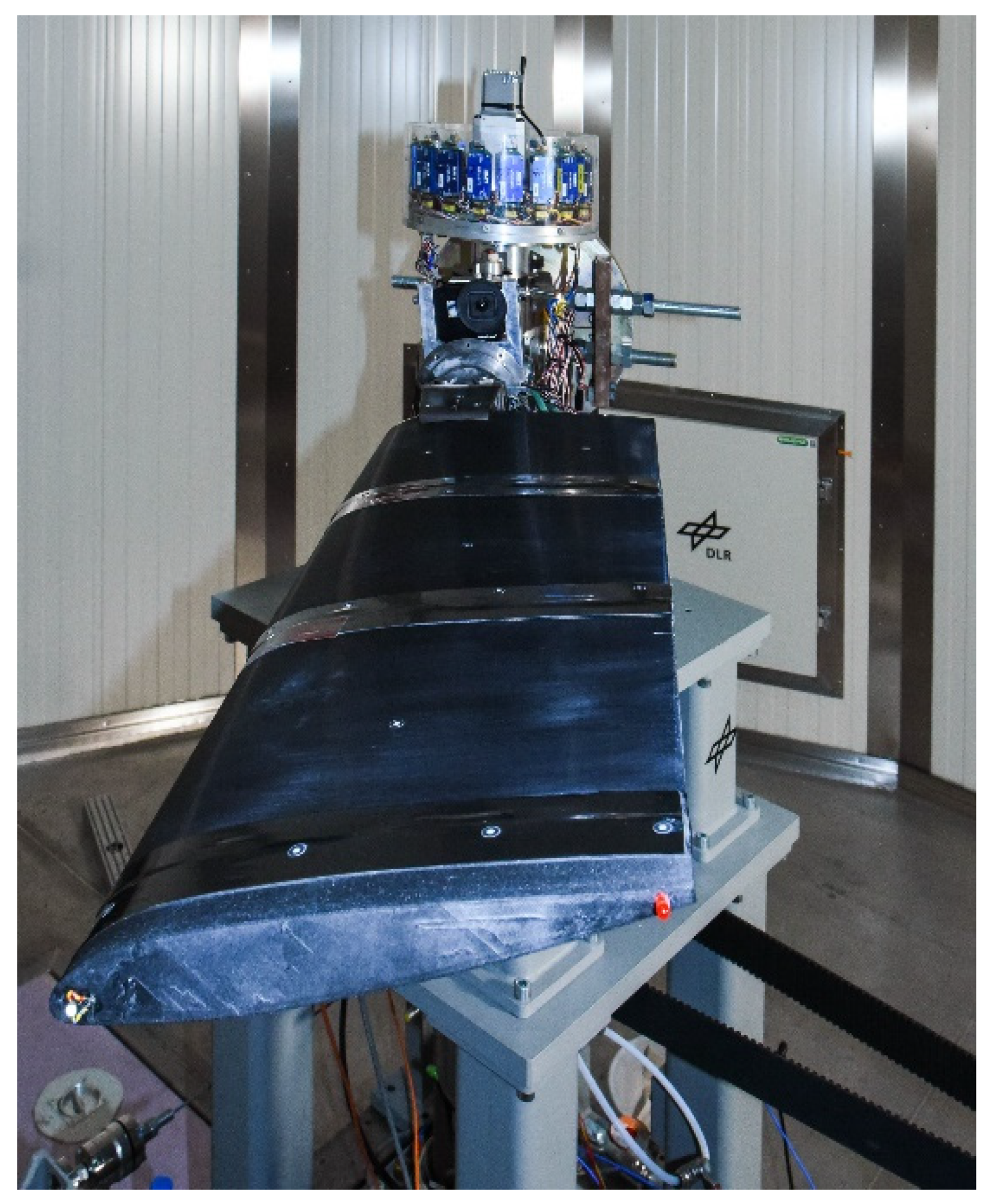
Figure 1 illustrates the blade prototype investigated in this work, installed on the axis of the WhT. The supporting rig of the facility can be seen on the bottom. Behind the blade the vertical axis of the WhT is visible, integrated with the sliprings and the interfaces with the sensors and actuators installed on the prototype. Since there is no scale to measure lift or drag implemented, this facility is more meant to examine functionalities or structural loads such as strains within blades. To be as versatile as possible, the test rig features 16 data acquisition channels in the rotating frame, which are used for strain gauge as well as ICP sensors and 45 × 24 V data slip rings with a max of 2 A, 5 slip rings capable of 2000 V at 2 A, as well as a slip ring for pressured air and two for water-glycole media to be transferred from the rotating to the non-rotating frame. The maximum radius of the test specimen is 2 m at a maximum rotation speed of 1200 rpm. This rig is designed for the test of single blades. Counterweights are used for balancing. A summary of the main features of the WhT is reported in
Table 1.
The centrifugal actions and the impossibility of simultaneously stopping the rotation of the test articles for any unexpected event impose the satisfaction of requirements strictly related to safety:
Structural integrity: for all the parts of the structure a safety factor (allowed stress over actual stress), SF > 2 must be guaranteed, with the exception of the SMA actuation components; the structure was safely sized to bear the loads without the contribution of the SMA elements that are duly pre-loaded to produce enough martensite for full recovery. Even if the stress level thus generated in the SMAs gives a safety factor of 1.6, the specific design layout that includes the SMAs within the main structure mitigates any risk related to the centrifugal projection of fragments.
Temperature: the operational temperature of the SMAs for this application was set at 150 °C; the design of the structure and of the actuation subsystem was in fact addressed to ensure the required twist at this temperature, in the presence of the imposed pre-twist. This temperature value is also compliant with the maximum allowed, 175 °C, in the whirl tower plant. However, since the temperature setting is addressed by a control system on ground, to prevent any fault of the transmission chain, of the temperature sensor, and of the controller itself, a dedicated network of current and temperature fuses was inserted into the power supply chain.
Mass distribution: the position of the center of gravity, xCG, must meet the condition to avoid any instability. Within this scope lumped masses within the leading-edge zone were placed.
For sake of clarity, a summary of the requirements and relevant design choices was reported in
Table 2. In the next section and in
Table 3, the design approach and relevant outcomes are illustrated.
3. The Demonstrator for the WhT Tests
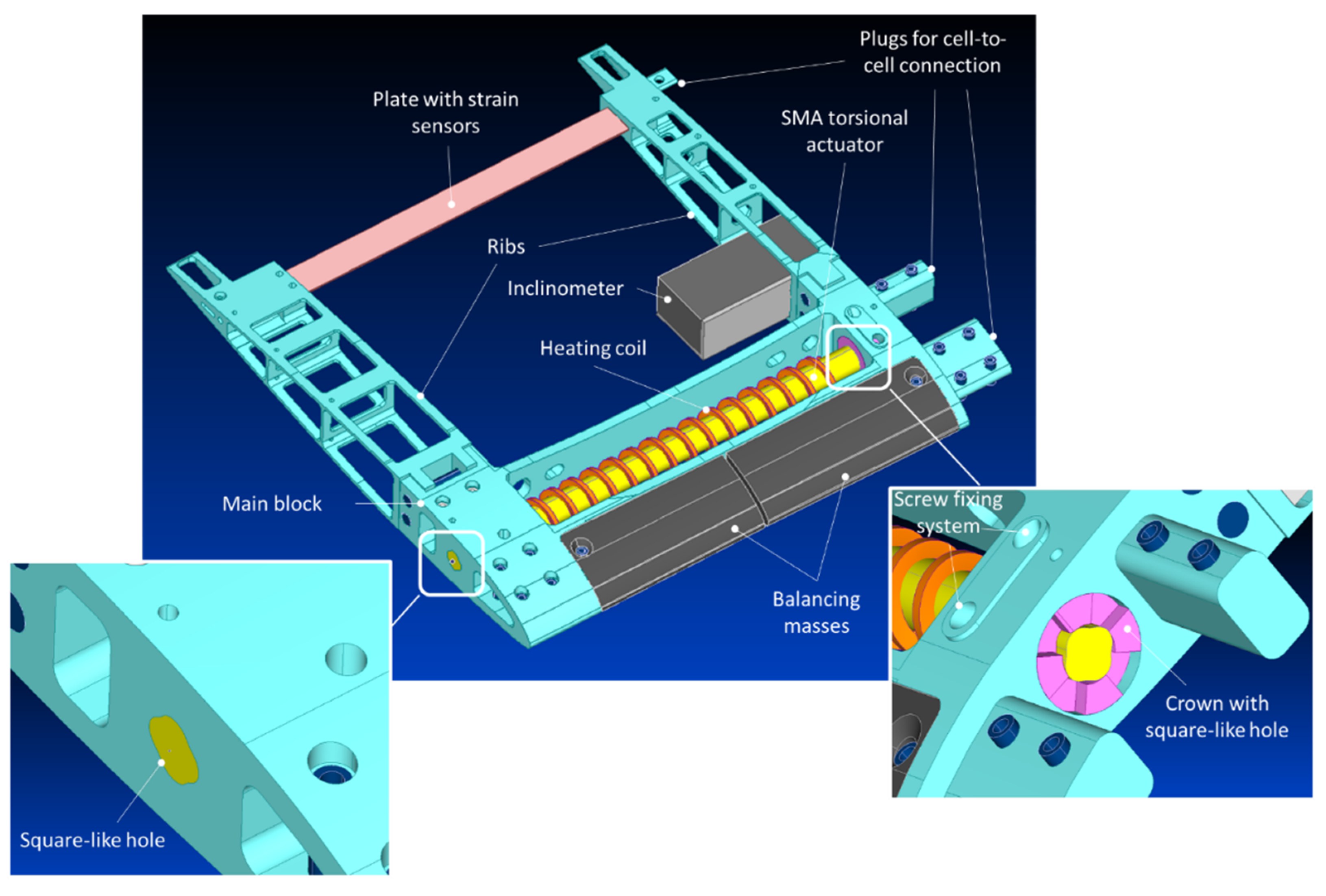
The prototype was conceived by adopting a modular approach. In practice, the final layout is constituted by different cells or bays, connected to each other along the span, to form a blade of a certain length. Each cell contains the specific morphing architecture chosen for actuating twist. Its structure consists of a main block and two ribs screwed to it (
Figure 2). This frame includes a shape memory alloy rod installed in the advanced part of the block [
42,
43]. One of its ends is housed directly in the block, while the other one is inserted in a steel crown that allows the pre-twist operation of the rod, necessary for the generation of an adequate level of martensite phase for the actuation. The SMA rod is wrapped with a helicoidal heater, driven by an external controller, inducing the phase transformation when additional twist is needed. The assembly process begins with the insertion of the rod inside the coiler. Then, one edge of the SMA rod is fixed into the square-like hole, highlighted in
Figure 2 in detail on the bottom left. Subsequently, a steel crown is coupled with the other edge of the SMA and, in turn, housed within the corresponding lateral block of the main structure, as shown in detail on the bottom right of
Figure 2 [
46].
The step-shaped lateral face of the crown is then used for applying torque and thus finalizing the pre-twist of the SMA. The crown is finally fixed to the lateral block through a screw system also highlighted in detail on the bottom right. The just mentioned square-like holes, along with this screw fixing system, assure a correct and efficient transfer of the torsion without any backlash-induced loss of twist, as well as the capability of minimizing stress, thus preventing early failures of the system.
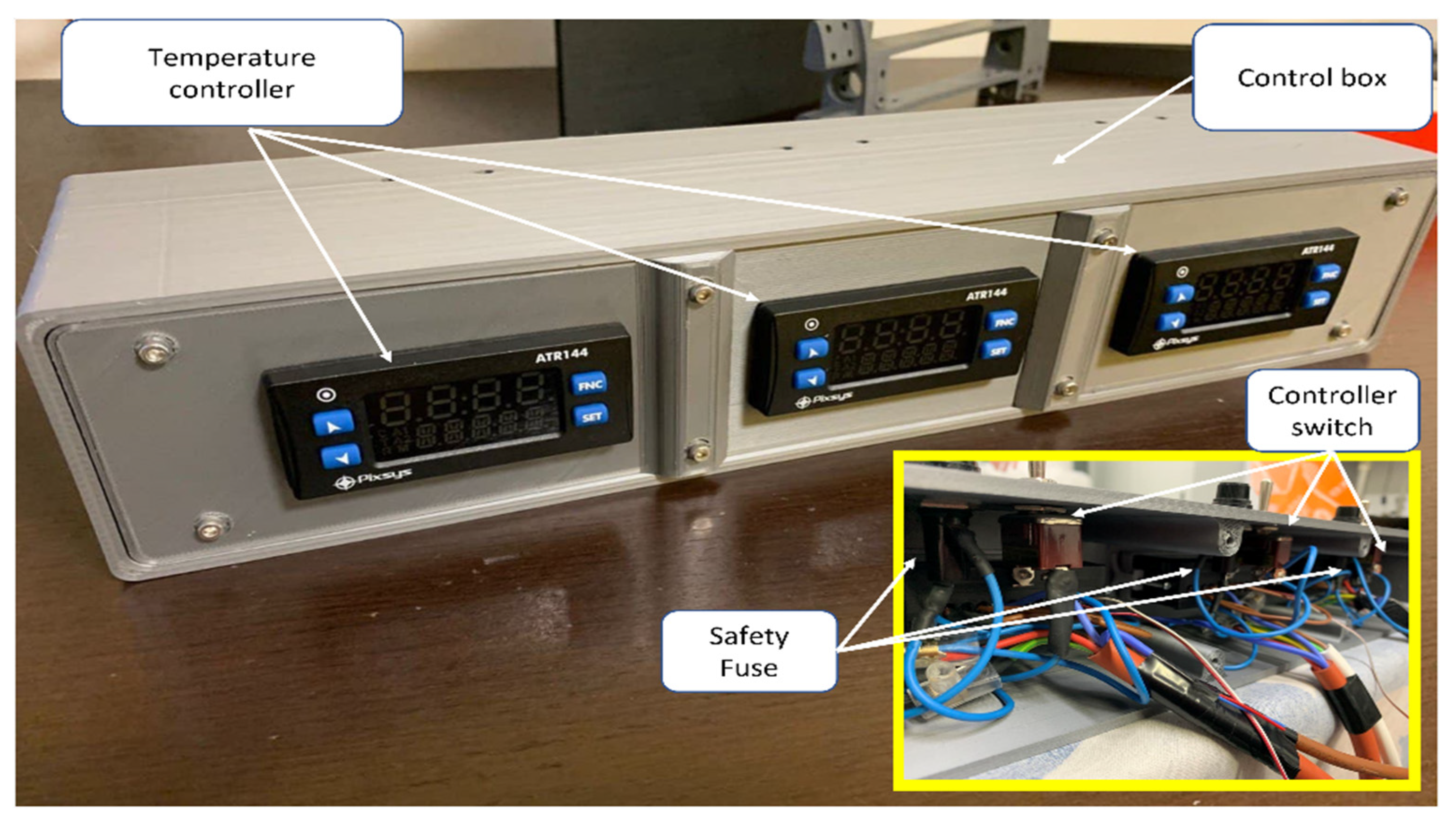
The actuation mechanism requires a temperature control system. It needs to be accurate, reliable, and needs to integrate mechanisms compliant with the safety requirements of the testing facility. To this end, two different actions have been undertaken: designing a control box (
Figure 3) to easily set and monitor the temperature, and integrating thermal fuses to prevent any overheating.
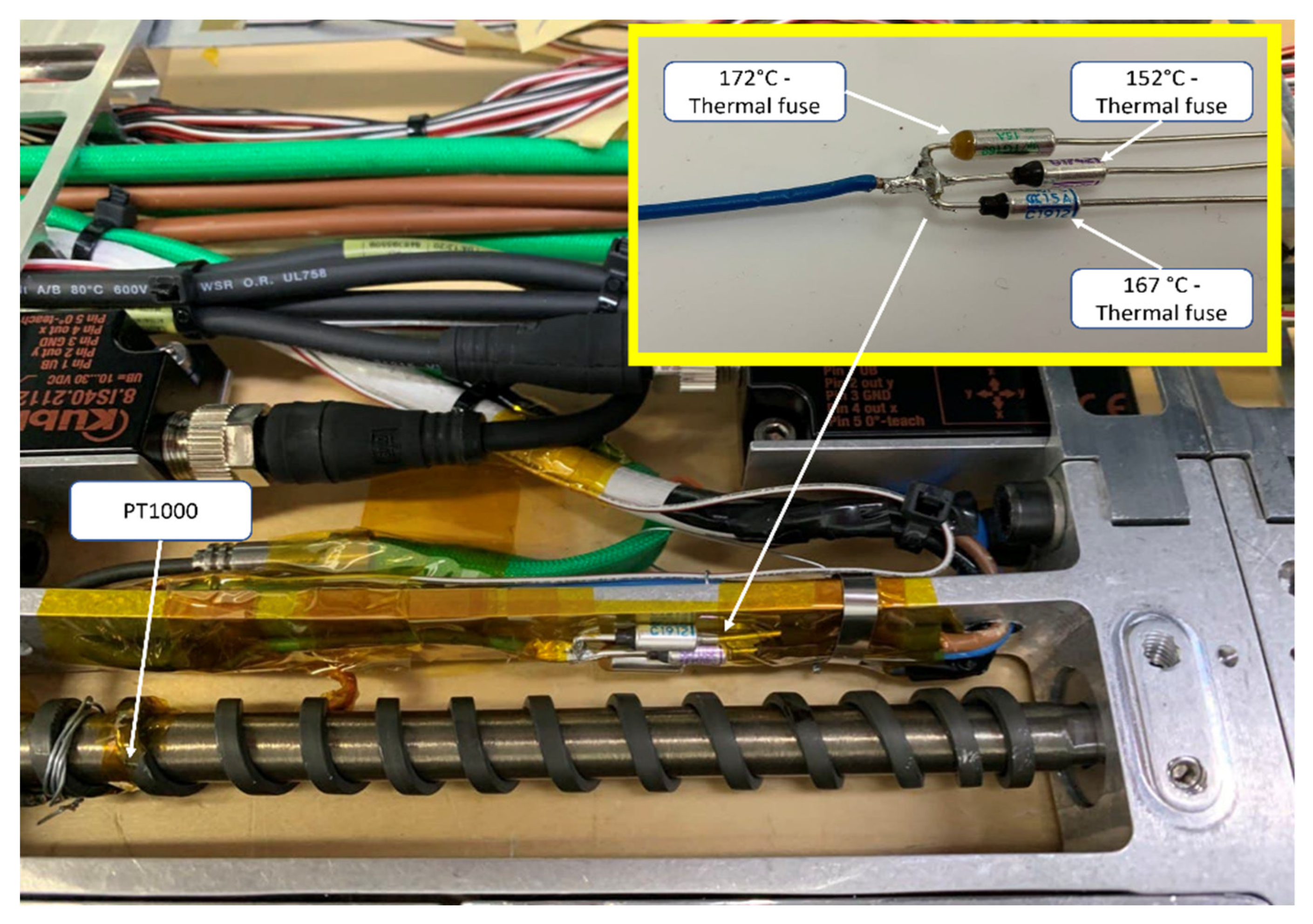
The control box allows for hosting three different temperature controllers, each one regulating the power of the heating coil of a given bay. A PT1000 T/C was placed within the second quarter of the SMA rod of every bay (
Figure 4), between the heating coil and the rod itself. The acquired temperature value was used by the thermal regulators to control the relè that allows the heaters to maintain the design temperature. A switch and a 20 A power fuse guarantee the safety requirements.
To prevent the abovementioned overheating of the coils, a thermal fuse was also inserted to stop the heating coil if the thermal regulation system fails to acquire the right temperature. Given the complexity of the internal harness configuration, a “3-way” thermal fuse control system has been foreseen (
Figure 4). This is because disassembling the whole system to replace a tripped fuse would require more effort than having three different fuses inside the assembled system. If an overheat of the system occurs, the heaters could power using one of the other two available fuses.
Resistive 120 Ohm strain gages (SG) uniaxial sensors (235SL series, with a gage length of 5.95 mm and a grid width of 2.54 mm) were bonded on the plates located close to the trailing edge of each bay (see
Figure 2) using an epoxy resin compliant with the expected range of deformation. For each bay, the strain sensing network was designed to decouple flap and twist effects in terms of strain measurements. To accomplish this task, the supporting plate was pre-sensorized according to the sensor network layout shown in
Figure 5. This plate was installed at each bay, clamped on one edge into a rib, and slid on the other edge into the other rib.
Gauge sensors measure strain in only one direction. However, in-plane strain at a point consists of two normal strains and one shear strain. The only actions transferred from the system to the beam are a transversal force and a bending and torsional moment at the free edge. The just mentioned layout was defined to split the pure torsion from the bending (flapping contribution). In fact, the axial sensors on the middle of the plate detect strain (particularly shear) just for pure torsion, while all the sensors measure strain for bending actions. Through a dedicated shape reconstruction logic and a preventive calibration on the basis of pure solicitations, it is possible to distinguish among the different contributions.
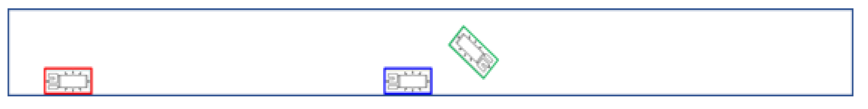
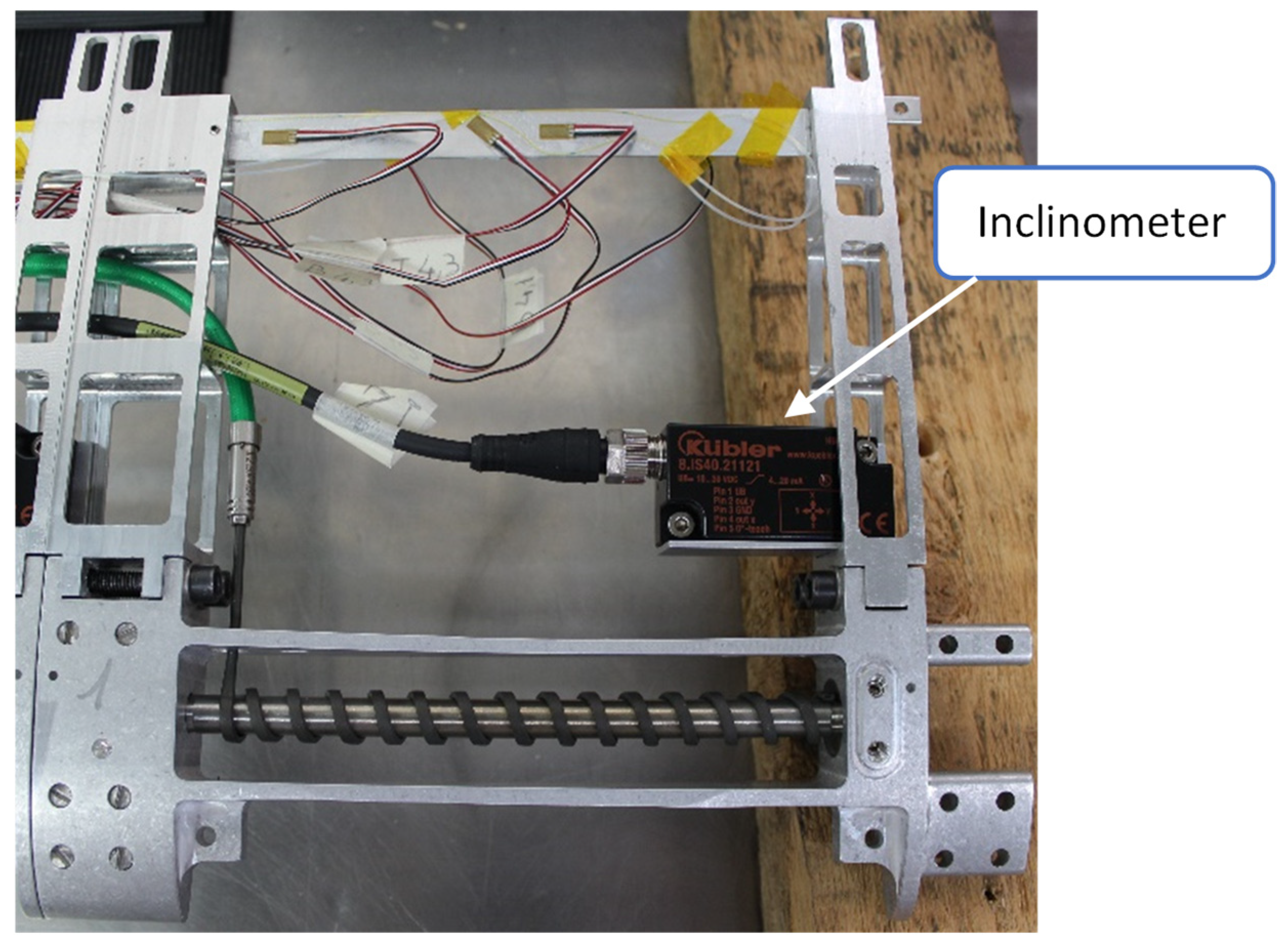
In order to monitor the inclination angles of the system during the torsional SMA-based actuation, each cell was also equipped with a two-dimensional inclinometer. The main purpose of such a dual axil sensor was to provide stabilized data of both tilt and azimuth angles with respect to the field of gravity in the range ±45° with a resolution of 0.1°. Due to the small design and minimal space requirements, this device was particularly suitable for the envisaged application, requiring accurate analogue output signals with limited impact of external vibrations and ambient disturbances. Such 50 g sensors having a voltage output in the range 10–30 V DC were calibrated over this range so that the output values were set to the corresponding angles.
Figure 6 shows the location of the inclinometer into a cell.
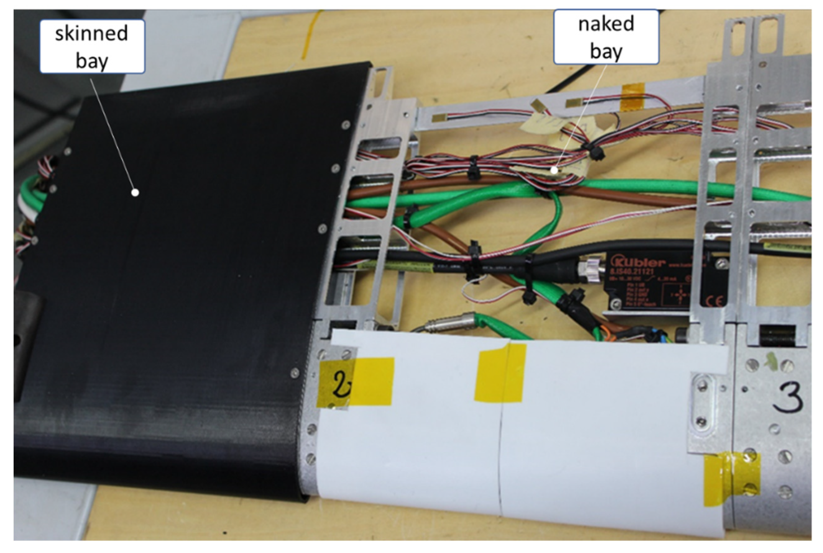
The skin needs to guarantee the correct aerodynamic shape to the assembled system, sustaining both the aerodynamic loads and stresses given by the morphing actuation system. Moreover, the skin needs to neither further stiff the assembled system, nor alter the performance of the torque actuator.
To be compliant with both geometric and mechanical requirements, an FDM process has been chosen for the manufacturing of the skins itself. Two different materials were tested: ULTEM™ 9085 Resin [
47] and ALFANYLON CF [
48]. The higher HTD (Heat Temperature Deflection) of the former makes the ULTEM the chosen material. In
Figure 7, a bay covered by a 1.8 mm thick skin cover, and another one that is naked, are compared.
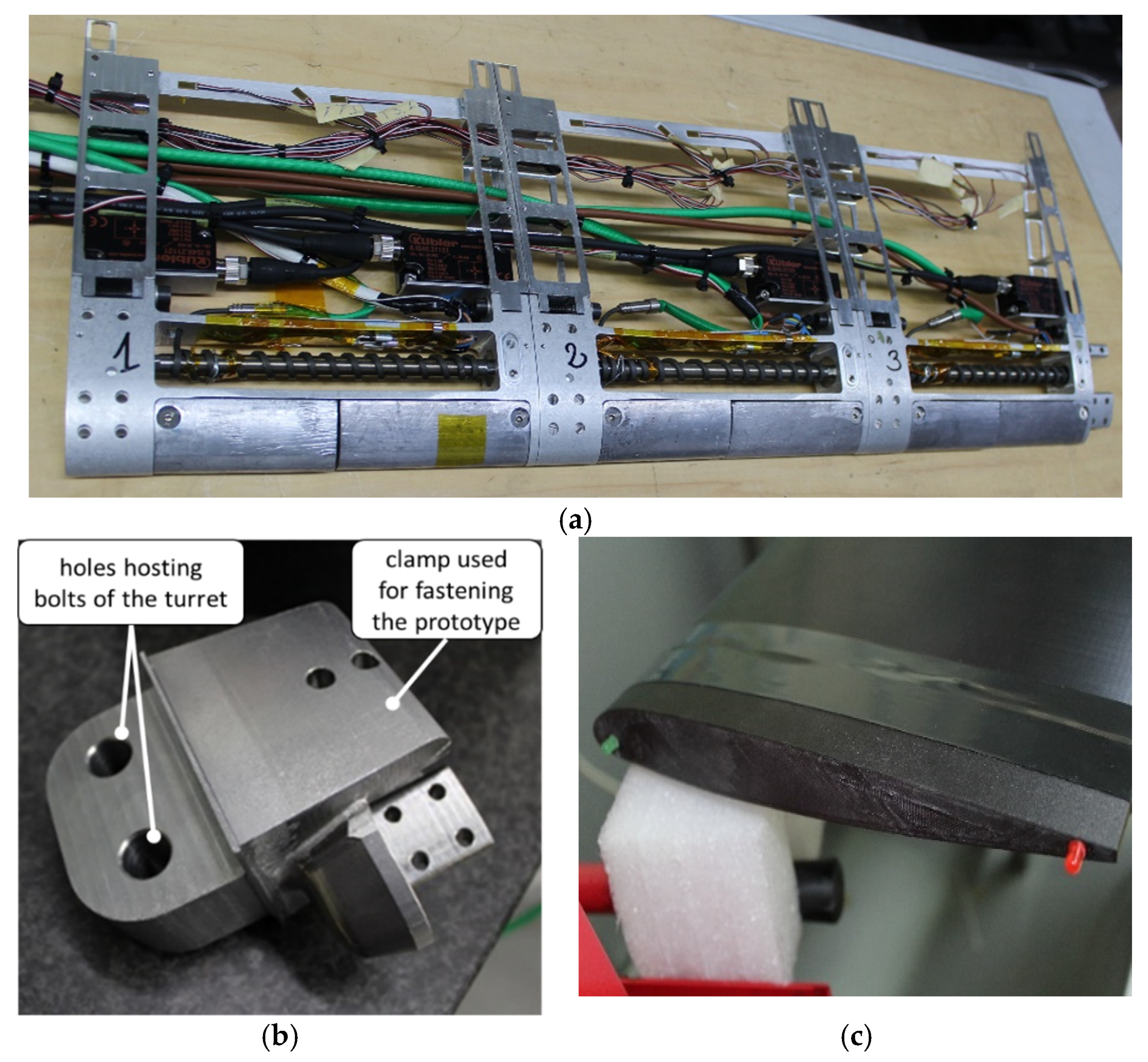
The demonstrator for the whirl tower was realized by connecting 3 cells serially, thus obtaining a total span of 660 mm. In
Figure 8a, the naked view of the device is illustrated. A numbering system from 1 to 3 was adopted in the next part of the paper to designate the bay from the root to the tip.
The root and the tip of the demonstrator were provided with flanges for the installation in the WhT, as depicted in
Figure 8b,c. The wiring passes through the root flange and runs up to the slip rings of the WhT. The tip flange is installed with two LEDs, one at the leading edge and the other at the trailing edge. All metallic parts are linked each other’s through high strength steel alloy pins.
The WhT demonstrator was conceived for being horizontally mounted onto the rotary axis of the test facility. The steel root connection flange shown in detail (b) is designed to integrate with the rotor turret interface system (proprietary of the WhT) for setting the attitude of the demonstrator. It is fixed to the left side of the structure (a) screwed through vertical bolts passing through the clamps. The other side of the flange presents two holes for the passing of bolts fixing it to the turret interface. The tip flange is made of ULTEM and has inside cavities to host the LEDs and prevent their expulsion during rotation. Transversal holes host bolts to fix it to the right side of the structure (a). The two LEDs embedded into the tip were used during tests to track the current attitude.
Finally, in
Table 3, the main features of the WhT model are summarized.
Table 3.
Main features of the WhT model.
Table 3.
Main features of the WhT model.
| Feature | Value |
|---|
| Chord | 270 mm |
| Span | 660 mm |
| Cross section | NACA 23012 |
| Original twist | −2 °/m |
| Weight (without connecting flange) | 5.71 kg |
| Skin material | ULTEM |
| Skin thickness (Figure 7) | 1.8 mm |
| Main structure material (Figure 2) | 7075-T6 aluminum alloy |
| Ribs material (Figure 2) | 7075-T6 aluminum alloy |
| Crown with square-like hole material (Figure 2) | 15–5 PH steel alloy |
| SMA rod material | NiTinol alloy
(55.79% of Ni, 0.11% of C, O, Cu, Fe, Co, Cr, Nb, H, N, balance Ti) |
| Plate with strain sensors material (Figure 2) | 7075-T6 aluminum alloy |
| Balancing masses (Figure 2) | Lead |
4. Laboratory Characterization
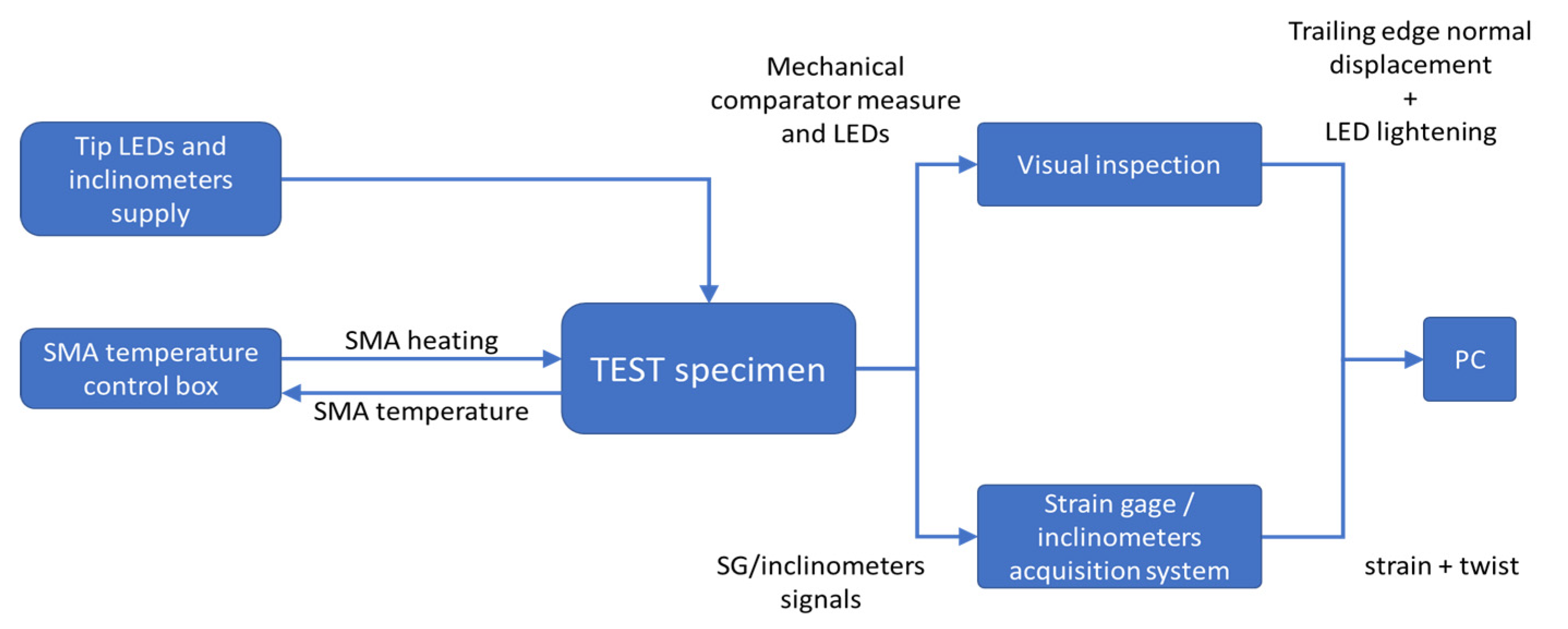
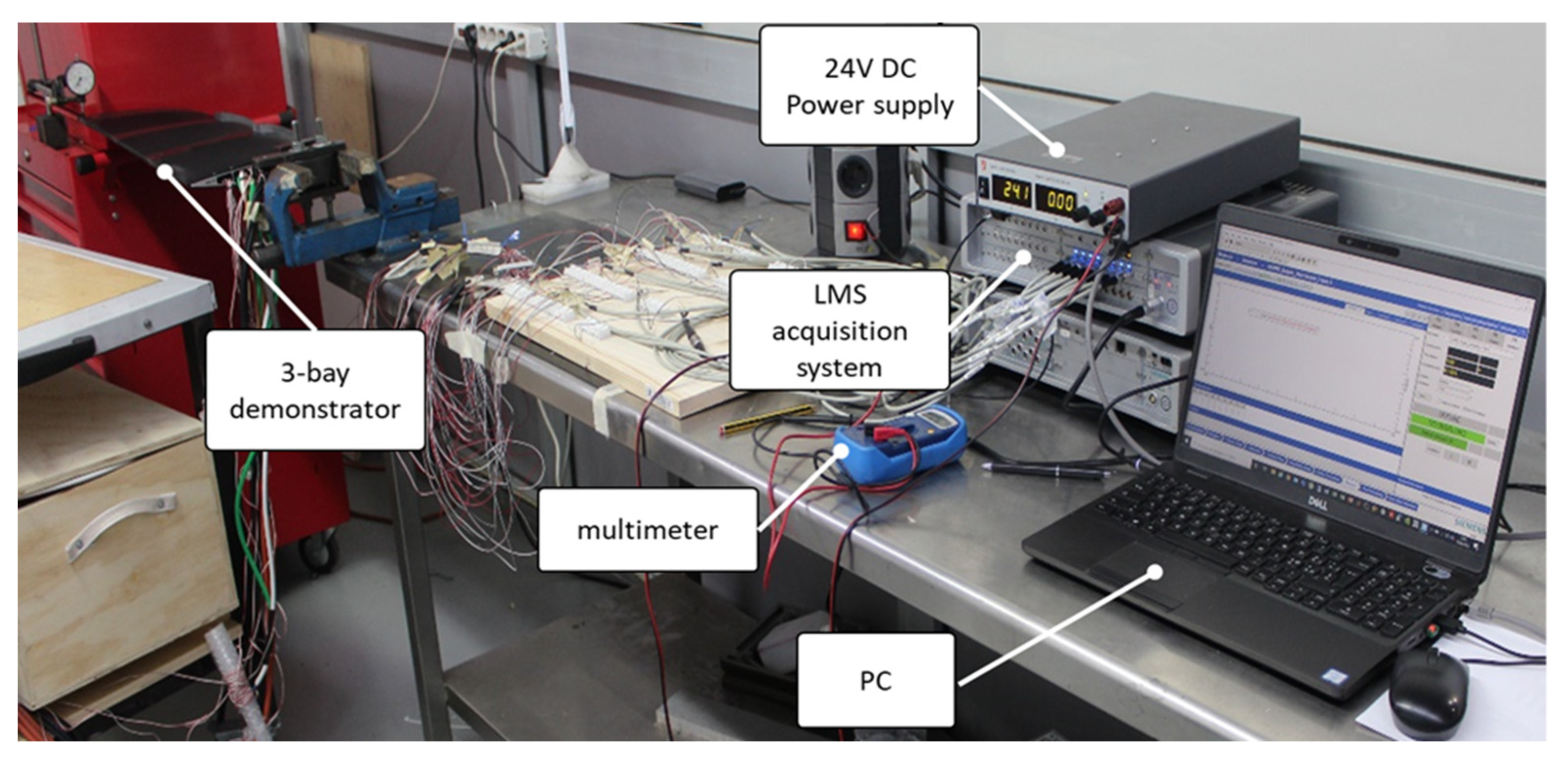
The scope of the laboratory characterization was to verify the functionality of all the subsystems of the prototype before its shipment and installation into the WhT. A dedicated setup was assembled to reproduce the WhT constraint condition, that is to say, the clamp at the root. The block diagram and a picture of the setup are illustrated in
Figure 9 and
Figure 10. The temperature of the heating coils is regulated by the three independent controllers described in the previous section; they are represented by the block on the bottom left of
Figure 9. The other two subsystems, the two LEDs on the tip and the three inclinometers mounted at each bay plus the one at the root are supplied by an external 24 V DC generator (top left block in the picture). The effect of the twist produced by the SMA is then measured by the strain sensors mounted on the supporting plates of each bay, the inclinometer sensors, and a mechanical comparator installed at the free edge of the prototype for visual inspection. The LED functionality is also visually verified. To acquire and elaborate the signals produced by the strain gages and the inclinometers a dedicated acquisition system (Siemens, Munich, Germany LMS SCADAS III) was used.
A list of the equipment is reported in
Table 4.
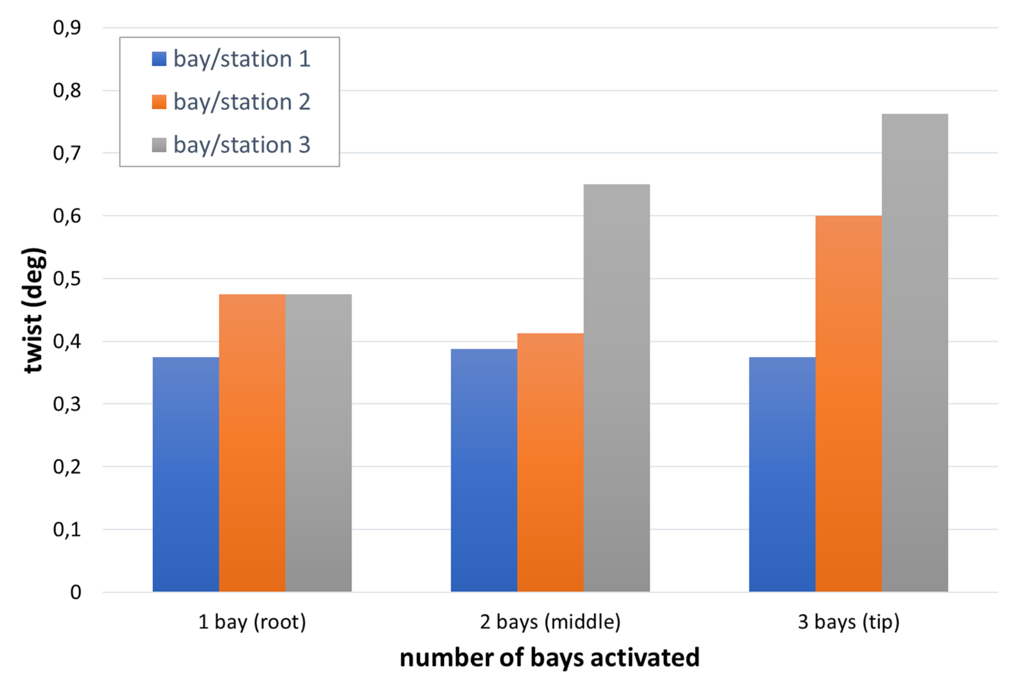
The tests were executed progressively, activating the bays from the root to the tip; each heating-coil was switched on arriving at the set temperature (150 °C) then left alone for 150 for stabilization and to verify the capability of the different components (the skin in particular) to withstand the thermal load. At the activation of each bay, the twist produced at the bay-to-bay interface stations and on the tip was measured by the inclinometers and correlated to the signal provided by the strain gage sensors.
In the bar plot of
Figure 11, a summary of the measurements is reported.
The bars of the front and middle rows (root and middle station, respectively) do not exhibit a clear trend with the number of bays switched on. On the contrary, the bars of the back row show a clear increasing trend. This is presumably due to the fact that the twist occurring at each single bay is practically at the edge of the inclinometer sensor accuracy. Only the geometric amplification occurring at the tip seems enough to outline a clear trend. The cumulative effect of the twist given by all three bays also contributes to the clear increasing trend exhibited by the last bar line on the right. The maximum twist measured at the tip was about 1.1°, over a span of 660 mm, corresponding to a twist of 1.667 °/m, slightly higher than the requirement (8° for a radius of 5 m), which is 1.6 °/m.
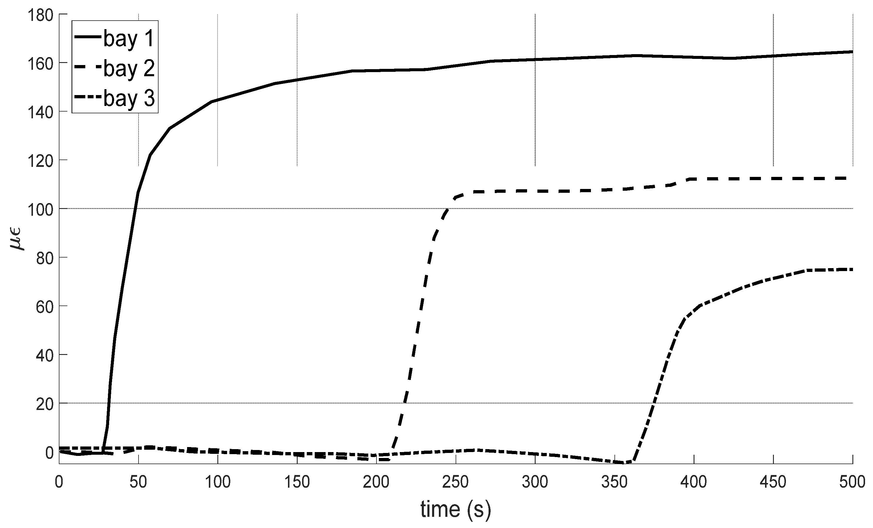
The strain measurements acquired by the SGs at the root of the interior sensored plates are shown in the plot of
Figure 12, per each bay. The different magnitudes highlight the greatest contribution given by bay 1, almost 1.4 and 2.2 times the second and third bays, respectively. It is however worth noting that this result could also be due to losses strictly linked to the internal friction between the sensored plates and the blade structure.
5. WhT Tests
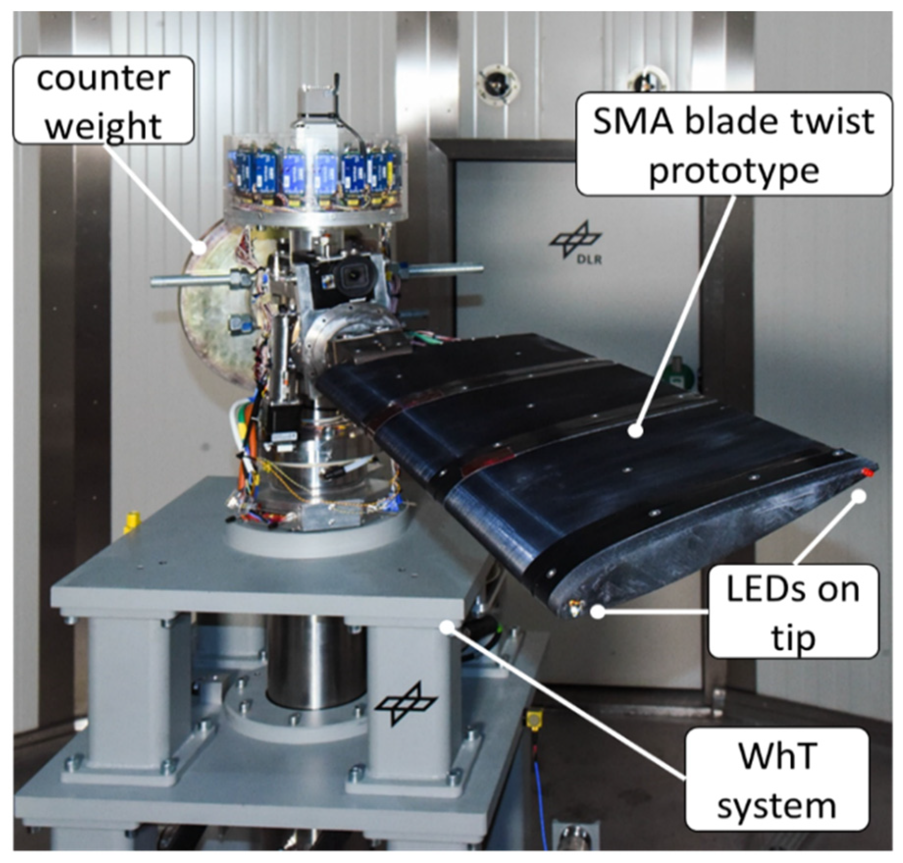
The demonstrator rotor blade was installed in the test rig as seen in
Figure 13. Since this was a single blade test, a counterweight for balancing was installed and a balancing procedure was carried out.
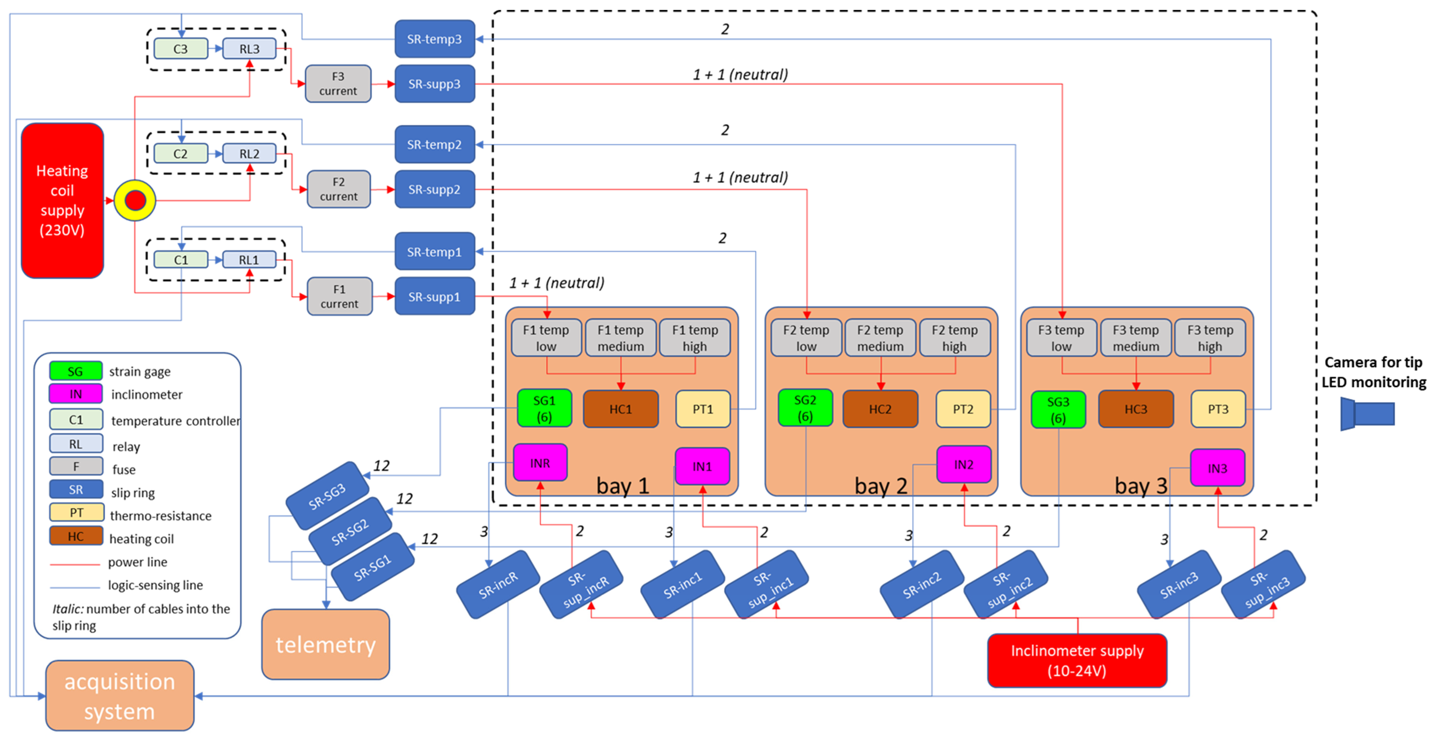
Electrical contacting included the energy supply for the heating coils and blade tip LEDs as well as wiring for strain gauges, temperature sensors, and inclinometers. Temperature control was done by the ATR144 controllers mentioned above, using the temperature signal of the PT element and controlling the current towards the heating coils energy supply by a “switch on and off” logic. The inclinometers and the strain gauges, for the measure of the absolute angles and of the deformation, were connected to the facility through a dedicated slip ring connector cluster. An independent absolute measure of the tip twist was also possible via an optical measurement of the two LEDs installed at the blade tip, one at the leading and one at the trailing edge, which allowed an external online measurement by photos of the blade tip by a high-speed camera. The shape memory alloy actuators allowed a stepwise increase of the blade’s twist, measured by the change of pitch angle. For that, the SMA rods, similarly to what done during the laboratory tests, were progressively activated, starting from the root up to the tip. A detailed scheme of the instrumentation and of the cabling involved in the tests is provided in
Figure 14. The dashed box on the middle delimits the demonstrator, in turns represented by three square boxes, namely bays 1, 2, and 3. Each box contains the subsystems related to the actuation and sensing: the heating coil (HC) integrated with the low, medium, and high temperature fuses (F), and the temperature sensor (PT), the strain gages (SG) placed on the sensored plate, and the inclinometers (IN). All the SGs are linked to the “telemetry” block devoted to this type of sensors, while the inclinometers are linked to the acquisition system. All cabling passes through the slip rings of the facility, represented by the blue boxes in the scheme. The power lines are represented in red: the inclinometers are linked to the red box on the bottom, representing the 10–24 V supplier; the heating coils are linked to the lowest temperature fuses, in turn connected through slip rings to current fuses and finally to the control box modules, including the temperature controllers and relays for switch on and off the power circuits. All the controllers are directly connected to the mains at 230 V. Italic numbers were used to indicate the number of poles associated to the connection lines. Finally, the external camera pointed at the tip of the outer bay is represented on the right side.
The test matrix consists of 19 test conditions as a combination of rotational speeds and angle of attack as illustrated in
Table 5. At each of these test points the following sequence of actuation was executed, with all of the SMAs initially in a martensitic state (room temperature). At first, bay 1 (root) was actuated. Subsequently, after approximately three minutes, bay 2 was actuated as well and finally, after another three minutes, bay 3 (tip) was actuated. This is a state in which all three bays are actuated and the SMAs are all in an austenitic state. In the following cooling phase, the twist decreases until the initial values are reached and the measurement is stopped.
Note that 120 rpm, that is to say 12.6 rad/s, is about 28% of the nominal speed of the rotor (44.4 rad/s). A comparison between the test and the nominal conditions may be addressed estimating the tensile force,
N, acting on the root of the prototype and on a segment of the blade:
with ω being the angular speed, and
R,
r, and Δ
r the blade radius, the inner station, and the extension of the blade segment, respectively, while
λ is the weight per unit length. The first two integrals represent the centrifugal actions acting on the inner and outer edges of the segment.
Data and results for this estimate are summarized in
Table 6.
In practice the tensile force acting during tests on the prototype, 0.99 kN, is about 24% of the analog force acting on a blade segment at the same distance (0.3 m) from the rotational axis.
6. Results
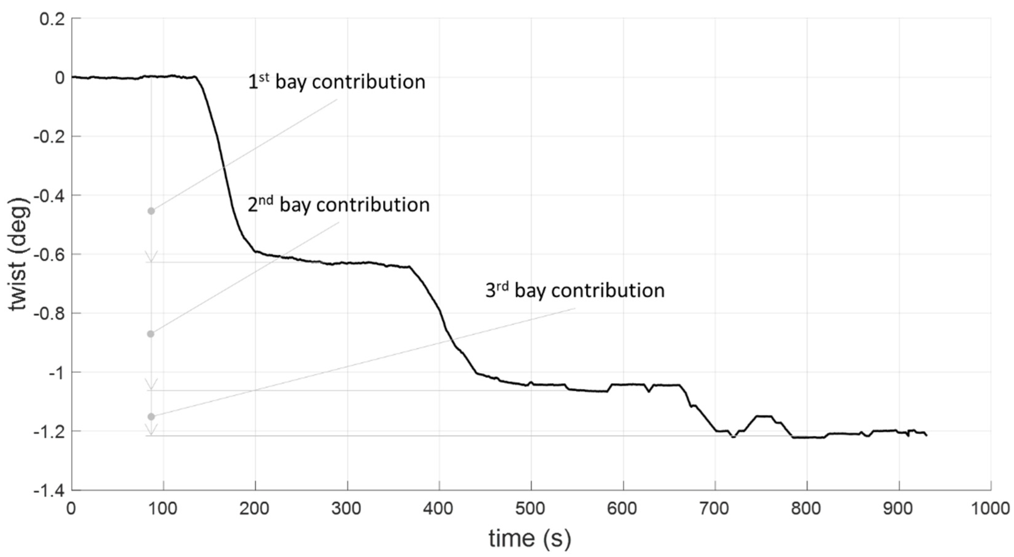
The obtained results were expressed in terms of twist and flap angle against the speeds and the angle of attacks imposed at the root of the blade. Both these angles were measured through the tip LEDs’ actual position. The angles were computed with respect to the tip position without any actuation. At first, an actuation at 0 speed was performed. In the plot of
Figure 15, the effect of the progressive activation of the three bays is shown in terms of achieved twist.
The activation of each SMA is highlighted by the sudden change of the slope of the curve, followed by a plateau that indicates the stabilization of the set temperature. The twist contribution of the actuators, 0.6° for the inner, 0.4° for the intermediate, and 0.18° for the outer bay, confirm the different magnitudes suggested by the strain measurements of the commissioning tests shown in
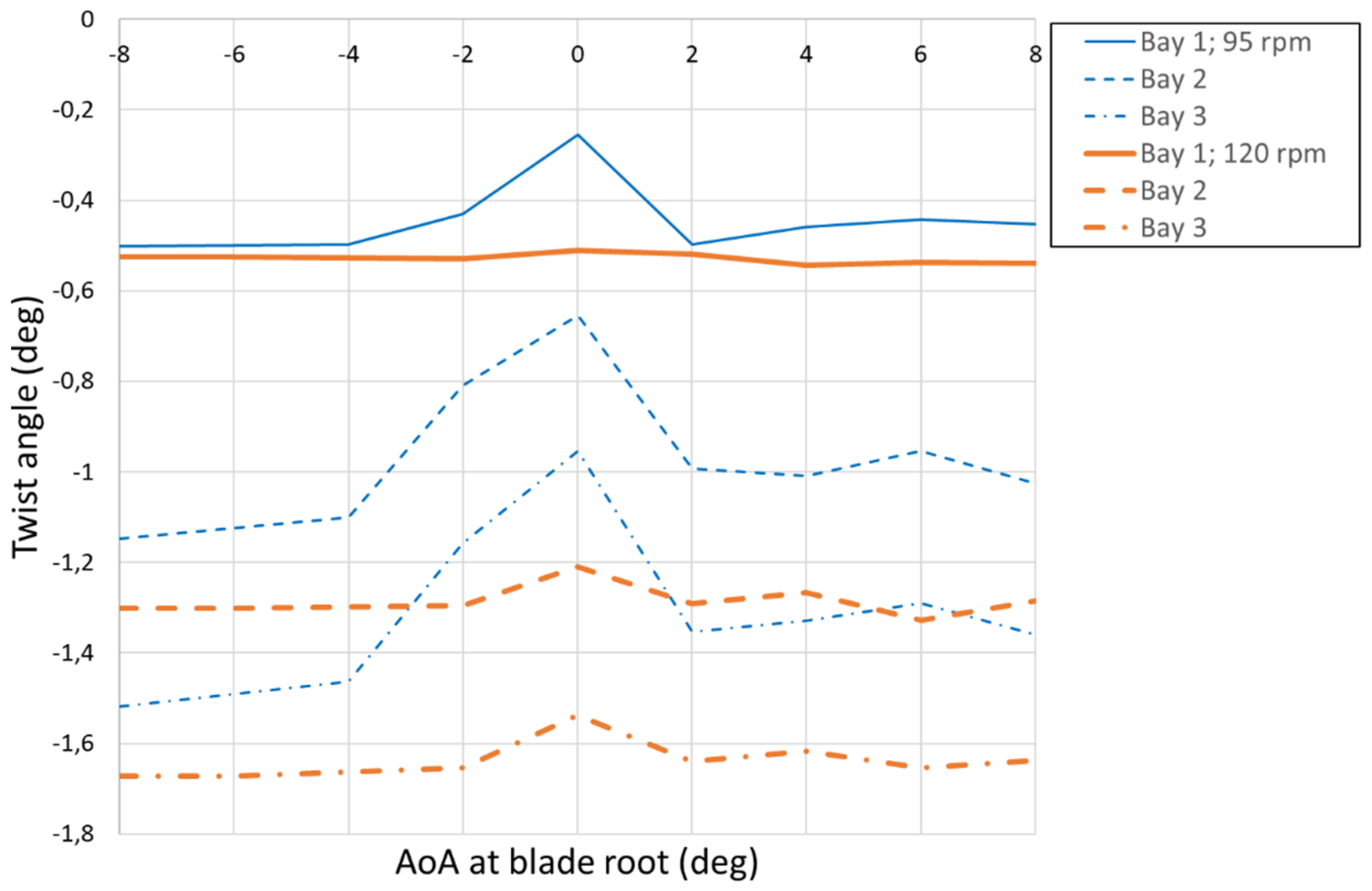
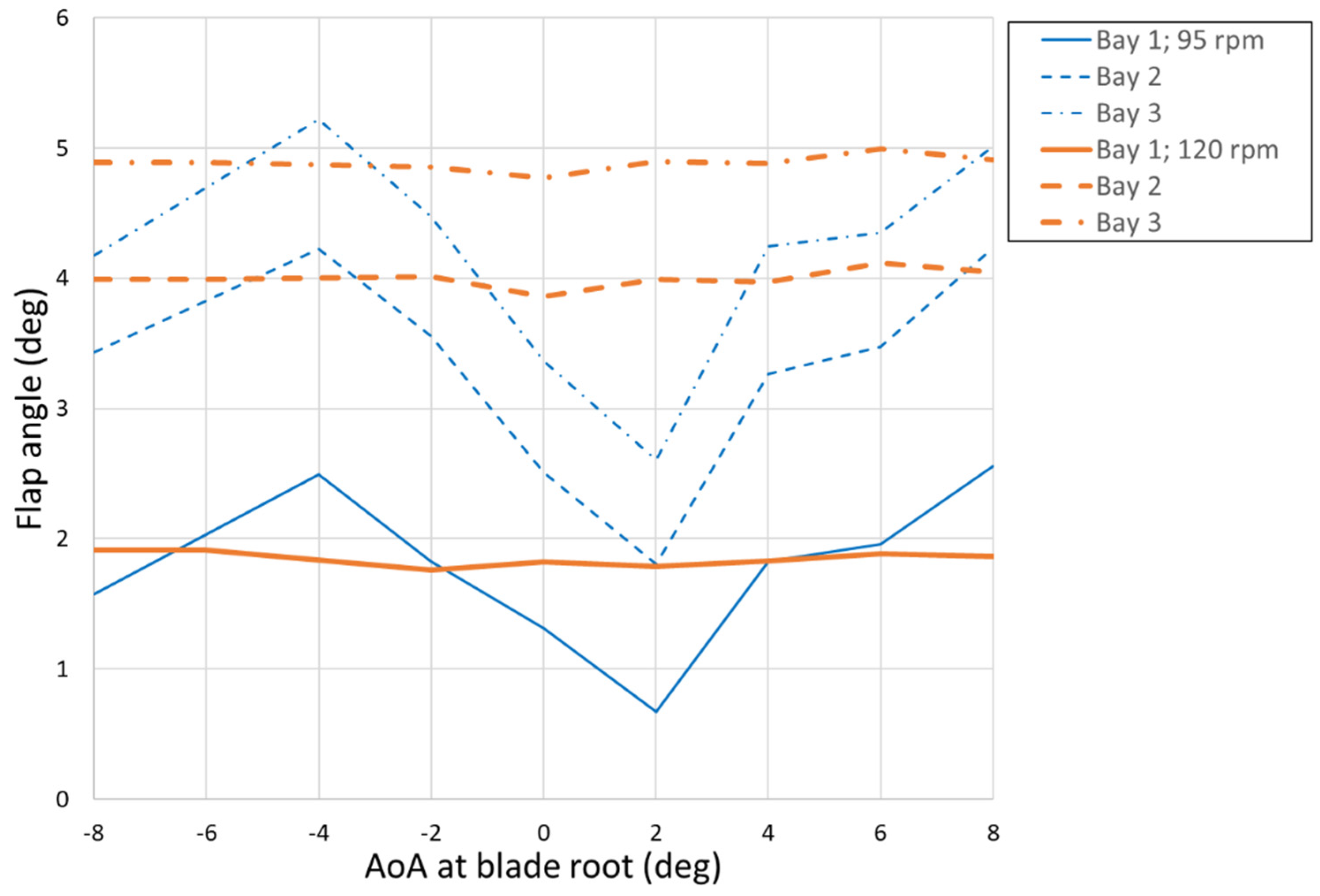
Figure 12. Then, the twist and the flap angles achieved at 95 and 120 rpm were measured. The plots of
Figure 16 and
Figure 17 show these angles when all the bays are switched on, by visualizing the position of the LEDs on the tip. The twist is maximum at an angle of attack, AoA, equal to 0, while it is constant for the rest of the range. The flap angle instead shows an oscillation with two opposite peaks at AoA equal to −4 and 2 deg. The attenuation of the just mentioned excursions is remarkable at the highest speed (120 rpm) and can be explained by the centrifugal action that tends to make smoother any variation along the blade.
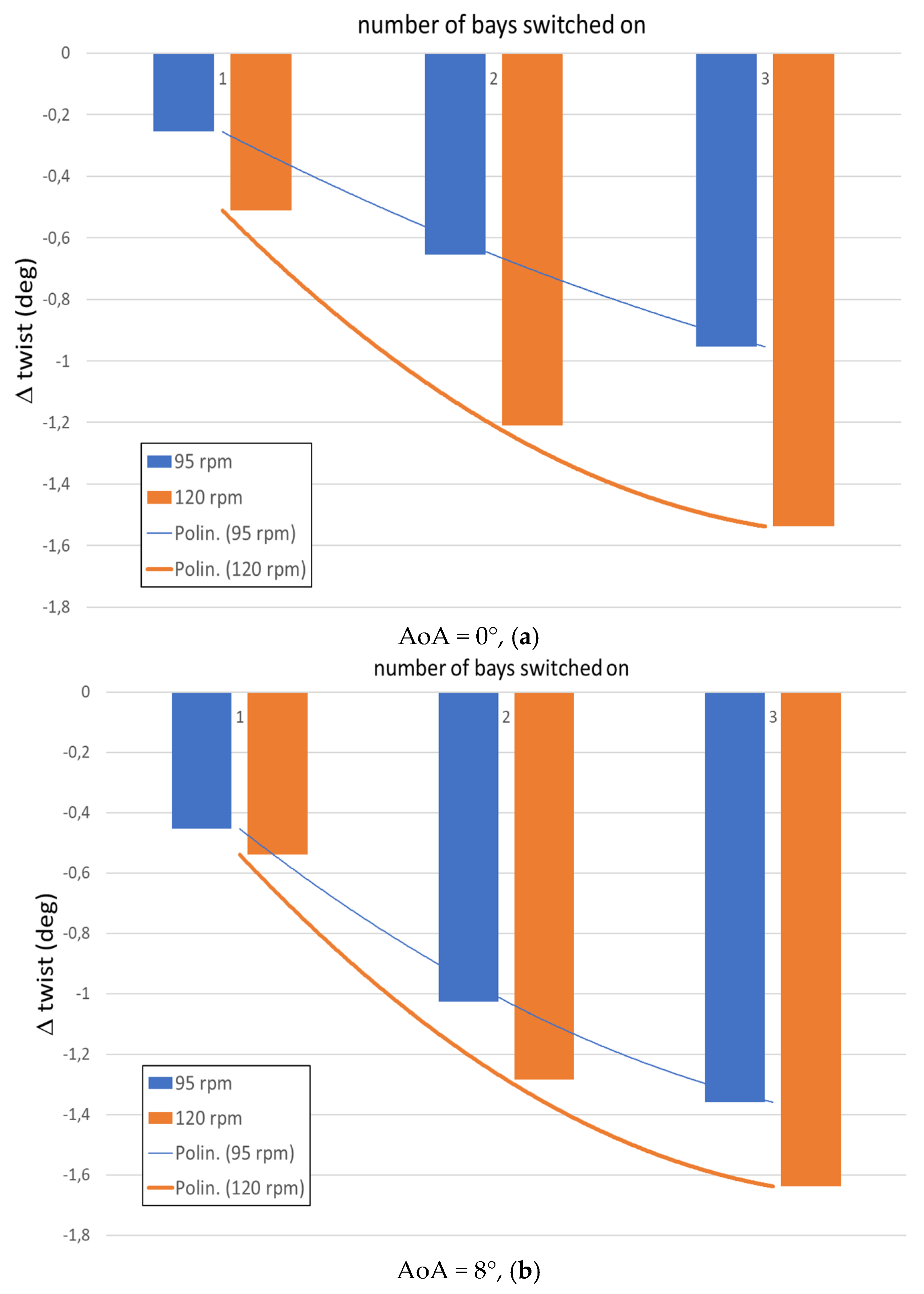
The effect of the progressive activation of the bays is then explored with specific reference to the twist and the flap angles at the tip. The bar plots of
Figure 18 illustrate, for the two speeds, the contribution of the activated bays to the increase of the twist at tip (namely Δ twist). The polynomial cubic lines highlight a cumulative, not linear, contribution to the twist, that points out a limited effect of the outer bays that is also in line with the actuation performance at 0 speed shown in
Figure 15. However, the speed effect is evident as it causes a more pronounced abatement of the slope of trend of the twist. Moreover, at the highest angle of attack, 8 deg, the deviation between the twist at the two speeds tends to diminish. Finally, it is also evident that twist benefits from passing from 95 to 120 rpm. This can be explained the higher magnitude of the negative lift that increases the pitch ward moment.
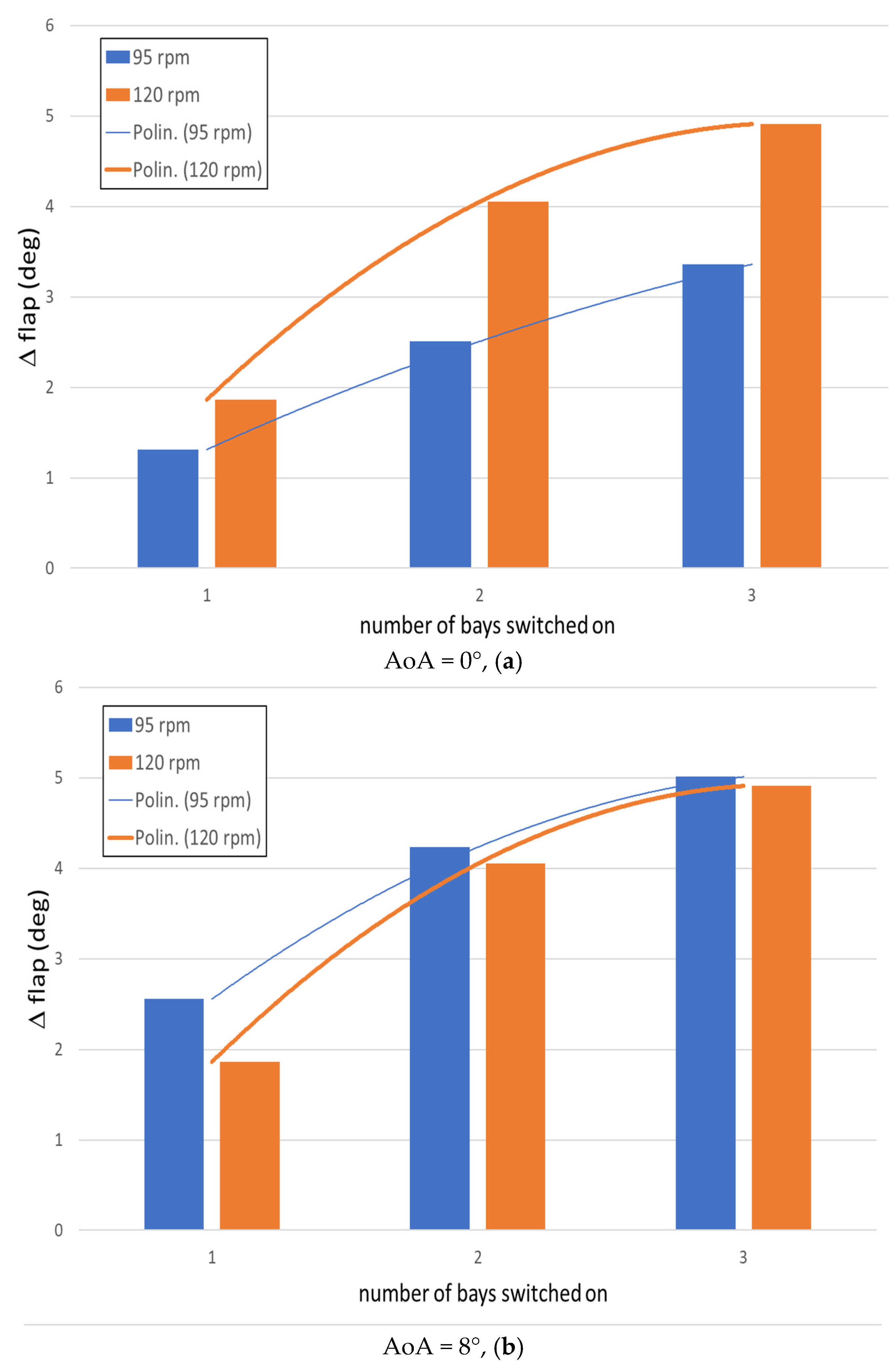
A similar behavior was also noticed for the flap angle (
Figure 19). Here at the highest angle of attack, practically the same flapping deflections are observed for the both the speeds considered. The positive increase of the flap angle can be explained by the progressive spacing of the frontal masses from the flapping plane, caused by the SMA pitch ward twist. As a consequence, the moments of the inertial forces increase producing a further upward rotation with the final effect of higher flap angles.
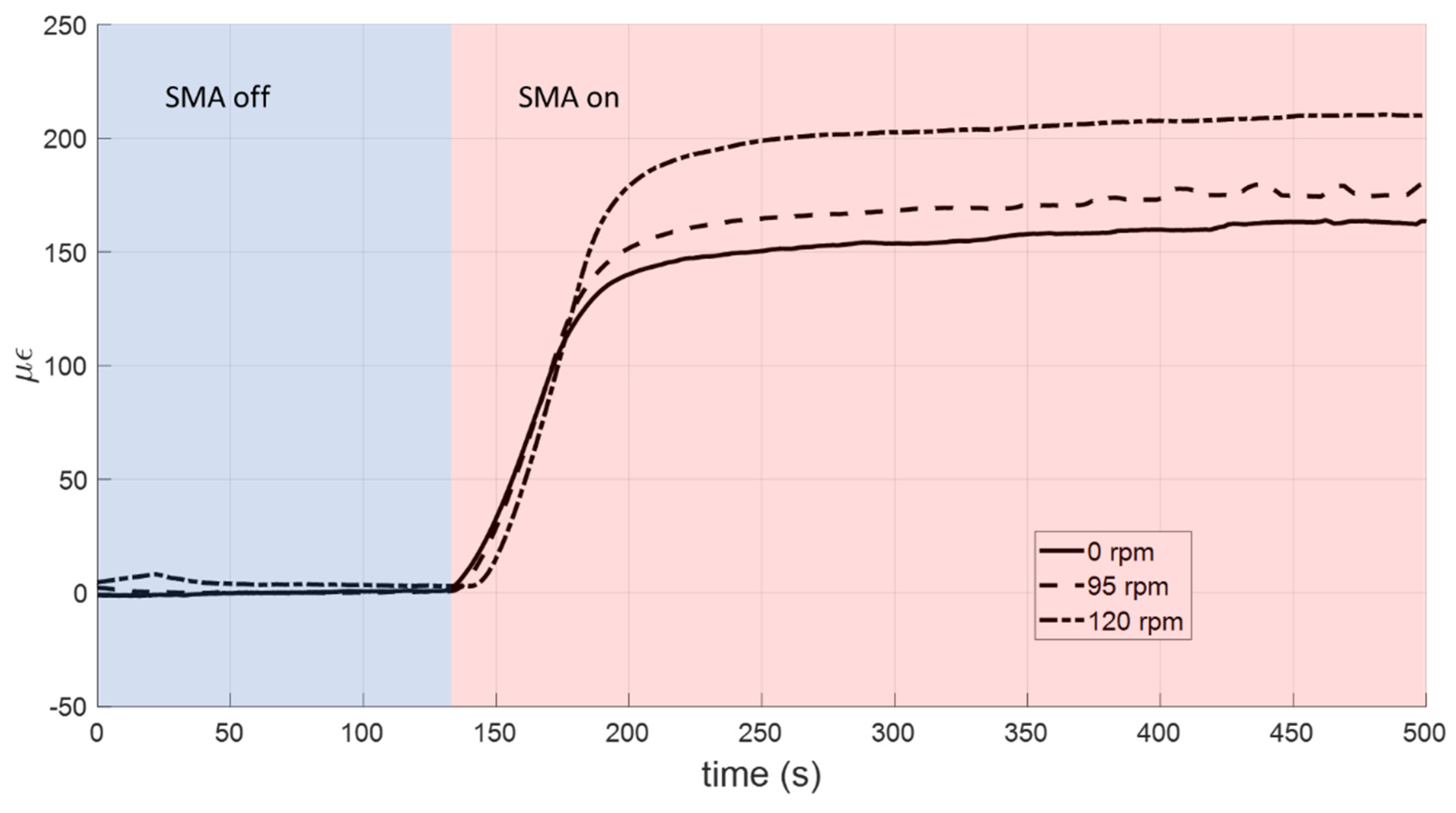
The centrifugal load has an impact also on the strain level; in
Figure 20, the deformation measured by the strain gage sensor mounted at the root of the sensored plate of the 1st bay is shown against the speed. The SMA is kept initially off at room temperature for about 120 s (blue zone); then it is switched on and arrives at the full activation within few seconds (red zone). The axial action due to the centrifugal load leads to an increase of the strain of about 13 and 48 με with respect to the case at 0 speed. This qualitatively offers an idea of the strong nonlinear impact of the centrifugal action on the structural safety.
7. Discussion
The achieved results proved a substantial coherence of the functional parameters with the laboratory tests shown in
Figure 12. The system was able to work within the entire test envelope. As expected, the rotary speed caused a progressive stiffening outlined by the lower twist and flap angles achieved at the highest speed. A degradation of the twist transmission of about 6% was found out, passing from 95 to 120 rpm. A lack of twist was observed for both these speeds for angles of attack close to 0. Probably, at this attitude, the twist law determines a global counter twist that minimizes the action of the SMAs. Also, the different contribution of the bays to the twist had an impact on this. The smaller authority of the bay at the tip seemed not to be caused by the centrifugal action, but essentially by internal losses of the mechanism. This was confirmed by the strain measured during the commissioning and by the twist angle and the strain measured during the WhT tests.
The basic requirement of the system was defined to introduce a device able to shift the operating geometry of the blade from a shape suitable for the cruise flight to another closer to the necessities of hovering. In this way, a benefit allowing saving equal to 1% of the efficiency is expected, as illustrated in [
45]. Such a benefit, scaled to the typical life of a rotorcraft, should provide a significant economic advantage that can be estimated in several thousands of euros. This aim may be translated into the need for constructing a morphing twist device able to produce an overall pitch-ward rotation of 8° along the blade span, i.e., from the root to the tip. Such a deformation should be obtained by a clean geometry, in order to avoid that shape irregularities may give rise to aerodynamic losses, in turn requesting larger rotations. Scaled over a single bay of the many modular elements that resulted by the SABRE design, 220 mm long, this spec reduces to almost 1/3 of degree per part. This target was fully matched by the produced system. The SMA-based, load-bearing actuator system attained that figure using a clean, embedded mechanism which did not interfere with the external parts of the structure, particularly the skin. All these requirements were met by the proposed device.
In this preliminary release, some details that shall be improved in further realization concern the structural robustness. In fact, the realized structural system was tested for a centrifugal force that can be estimated at the 20% of the actual centrifugal force; that is to say, this percentage is derived through a combination of the number of rounds per minutes actually tested, and the different span length of the demonstrator. It should be remarked that a larger centrifugal force should not cause a reduction of the torsional effectiveness; however, the need to resist higher loads would lead to a stiffer structure, and would therefore be more resistant to general deformations. In spite of the relevance of this point, it could be simply overcome by a larger actuator tube, able to provide a larger activation authority; if a hollowed SMA cylinder is then considered, weight and cost savings could be achieved. It should be recalled that a rod has the relevant drawback of being only partially activated since its core remains martensitic no matter the external force. A thin hollowed cylinder would instead be characterized by a quasi-constant stress, with remarkable advantages in terms of material fatigue. A final consideration should be devoted to the stress required, i.e., the intrinsic structural tension that accompanies the device overall and its working operations. A higher stiffness implies, in turn, a higher initial stress (pre-stress) and a much larger terminal stress, since the characteristic working lines increase their slope, moving the final operation point towards the top. This aspect needs suitable and careful working and installation procedures, and may affect the device safety itself.
8. Conclusions
This work focused on the demonstration of a morphing blade twist system running into a whirl tower representative environment. The system is actuated through solid SMA elements that produce an additional twist, which has an impact on hover and vertical flight. The demonstrator was realized by connecting three bays along the span, each one integrated with an independent SMA actuation system. The demonstrator was tested in the WhT facility. At first, the demonstrator was actuated at 0 speed for reference purposes. Then, two speeds were explored, 95 and 120 rpm. The twist and the flap angles generated by the action of the SMAs were measured. The impact of both the rotational speed and the angle of attack imposed at the root was evident. The measured internal strain clearly pointed out the effect of the SMA actuation and the impact of the centrifugal force.
The main findings can be summarized as follows: this study demonstrated the capability of measuring actuated morphing characteristics (i.e., twist and flap angle) vs. test parameters as rotational speed, angle of attack, percentage of activated SMA material, and so on; it provided useful info for better understanding the complex phenomena that impact the shape of a twist morphing blade in terms of flap and twist angle within the entire test matrix domain; it defined a procedure for the evaluation of the contributions of the different loads on the overall morphing blade stress level (internal—as the actuation ones; external—as the aerodynamic, and the centrifugal ones).
These initial whirl testing results show that this SMA-driven twist concept can work under the presence of centrifugal loads. Particularly, actuation on the different bays the demonstrator was made of exhibited a significant deflection irrespective of their position along the span. This is relevant, since the centrifugal forces increase with distance from the rotational center. Indeed, a first evaluation at 0 speed denotes a certain difference of the three independent actuation systems. Since there is no rotation velocity, nor a flow speed, this result is correlated to the SMA generated forces, only.
In turn, this implies that a standardized realization process would definitely improve these first preliminary results, generated by a first, handcraft work. Therefore, there is a large margin of improvement ahead. As the structure does undergo both centrifugal and aerodynamic forces (related to rotation only), a favorable effect is observed as it moves away from the blade pivot. This effect may be attributed to the negative lift, which pushes further blade rotations around the torsion axis. It is believed that a further contribution is linked to the mass distribution. To cite an example, the flap angle increase with the progressive bay activation can be explained by the pitch-ward rotation of the masses that, in turn, generates upward restoring moments. If this effect is confirmed, it should be taken into account in the design process. These outcomes point to the conclusion that evolutions of the concept could exploit its potentiality well beyond what has been herein reported.
9. Future Steps
A main aspect that should be dealt in the future design of these systems concerns the accurate selection of the shape memory material, the real core of the device. Its function of working as both an actuator and a bearing element makes clear its critical role in the architecture of the smart blade. Today, SMAs are very common, and several industrial interests push the production of more and more performant, and even cheaper materials. Therefore, it can be expected that the market releases more appropriate products in the near future or, conversely, that technology is ready to produce elements with certain properties on demand. A compact actuator, replacing the original load-bearing element, may be the key for the success of the presented technology. Actuation is one of the possible showstoppers, requiring a discrete amount of energy for activation. On the other side, it should be considered that the resultant robustness is linked to the energy itself, in the sense that a significant reduction of the transformation energy in a reversible material can probably cause a poor stability of the transformed phase, which could be pushed back by the counteracting forces. Under these opposite effects, an optimal value can emerge and represent one of the possible specs for an appropriate material realization.
Future work in developing this concept can build on these promising results to further explore the performance of the system under increasing levels of loading to approach full scale values replicating the complex, time varying mix of centrifugal, aerodynamic, and inertial loads that such a system would experience in operation. This work would be undertaken in parallel to detailed analysis and design efforts that further optimize the structural efficiency of the design and the obtainable changes in twist upon actuation of the SMA. Of particular importance for this concept is the detailed modelling of the aeroelastic response of a full blade with SMA morphing sections embedded into it, as the global bending moment, shear, and torsional loads generated outboard of the morphing section must be transferred through the morphing components, and these (combined with the local loads) will drive the sizing and performance of the SMA actuators and of the spar structure they are embedded in. Response of the compliant skin material under global torsional loads is also of interest.
Significant work remains before this concept, and the others investigated within the SABRE program, are ready for real world application, but the results of this initial work show that the achievable twist performance is promising enough to warrant further research.


 ,
, 


