
Using a Robot for Indoor Navigation and Door Opening Control Based on Image Processing

Department of Communications, Navigation and Control Engineering, National Taiwan Ocean University, Keelung 202, Taiwan
*
Author to whom correspondence should be addressed.
Actuators 2024, 13(2), 78; https://0-doi-org.brum.beds.ac.uk/10.3390/act13020078
Submission received: 27 December 2023
/
Revised: 12 February 2024
/
Accepted: 15 February 2024
/
Published: 16 February 2024
(This article belongs to the Special Issue Actuators in Robotic Control: Volume II)
Abstract
:This study used real-time image processing to realize obstacle avoidance and indoor navigation with an omnidirectional wheeled mobile robot (WMR). The distance between an obstacle and the WMR was obtained using a depth camera. Real-time images were used to control the robot’s movements. The WMR can extract obstacle distance data from a depth map and apply fuzzy theory to avoid obstacles in indoor environments. A fuzzy control system was integrated into the control scheme. After detecting a doorknob, the robot could track the target and open the door. We used the speeded up robust features matching algorithm to recognize the WMR’s movement direction. The proposed control scheme ensures that the WMR can avoid obstacles, move to a designated location, and open a door. Like humans, the robot performs the described task only using visual sensors.
1. Introduction
With scientific and technological advancements, advanced machine systems are expected to replace human labor. Robots have always attracted considerable attention in the industrial technology development domain. In recent years, robots have been used to perform a few simple labor tasks. For instance, they are employed in unmanned factories, as vacuum cleaners, for restaurant service, and as tourist guides [1,2]. To allow robots to perform more tasks, it is important to conduct research on how to make robots intelligent and humanized. Diverse types of robots are used in different working environments. In this study, an omnidirectional wheeled robot is used in an indoor working area. Omnidirectional wheeled mobile robots (WMRs) are more flexible than ordinary moving robots as they can move in complex and narrow environments [3]. Omnidirectional robots can move in any direction without turning their heads and have been applied to many tasks [4,5,6]. In traditional robots, many sensors are installed to detect objects and directions. Obstacle avoidance is mainly achieved using ultrasonic and laser range finders or other distance-measuring instruments. Navigation is performed using a few positioning instruments, such as StarGazer, Bluetooth, or WiFi. In this study, we used cameras to replace traditional obstacle avoidance and positioning sensors to make the robot more human-like.
With advancements in artificial intelligence, intelligent robots have been widely studied. In recent years, omnidirectional wheeled robots with different control systems have been developed. Jia et al. developed an omnidirectional wheeled robot with multiple control Mecanum wheels [7]. Park et al. studied the fuzzy PID steering control structure of a mobile robot prototype [8]. Chung et al. modeled and analyzed an omnidirectional mobile robot with three caster wheels [9]. When robots could move, researchers began to study how to install obstacle avoidance components in them. Ruan et al. used ultrasonic sensors to confer obstacle avoidance capabilities on a two-wheeled self-balancing robot [10]. Jin et al. used a rotating ultrasonic sensor to endow a car with active obstacle-avoidance capabilities [11]. Peng et al. presented a laser-based obstacle avoidance scheme [12]. In addition to ultrasonic sensor–based avoidance, a few researchers have studied image-based obstacle avoidance. Wang et al. used a Kinect depth camera to detect obstacles [13]. They used the Kinect to obtain a depth map and subsequently applied a Gaussian filter and the mean-shift segmentation technique to detect obstacles. Hamzah et al. used a stereo camera to obtain a disparity map and then used the map to compute object distance and the direction of movement [14]. Sharifi et al. used the mean-shift color classification scheme to distinguish obstacles from the ground [15]. AI-Jubouri et al. proposed the use of a set of local features extracted from a sequence of image frames collected using a computer vision system. The extracted features for each free-swimming fish were then compared with pre-extracted sets of features stored in a database using the SURF matching method [16]. Their method yielded a high object recognition rate. Sheu et al. used two cameras to compute a target object’s deviation angle and distance and then used an adaptive PID control scheme for real-time target object tracking [17]. In our study, we integrated omnidirectional wheels, an Arduino system, a DC motor, a motor controller, a depth camera, and a robotic arm for indoor navigation. The control scheme involves applying image processing methods and feature matching to detect obstacles and compute the movement direction of a robot. The robot’s movement is based on fuzzy control.
This study mainly revised the traditional ranging paradigm. Range detection was realized by using an Intel Realsense depth camera. After computing the distance of an object, fuzzy theory was applied to avoid obstacles. During robot motion on a path, we used the speeded up robust features (SURF) algorithm to compute the robot’s self-position and future trajectory. Moreover, the cameras detected the static and dynamic obstacles encountered on the path. After arriving at the designated position, the control scheme used HoughCircles to identify a circular object so that the arm could find the doorknob and claw the door handle. Our experimental results indicate that the proposed visual control scheme can facilitate omnidirectional obstacle avoidance and help the robot move to a designated location and open the desired door. Compared to other relative research, most of them utilized laser and ultrasonic sensors in robot navigation [18,19]. To make the robot human-like, the proposed WMR system only uses visual information to avoid obstacles, navigate indoors, identify the door, and guide the robot arm to reach the doorknob. In addition, a simple fuzzy system is implemented in the control process that can reduce the computing time and is suitable for real-time control.
2. System Description
The proposed control system was realized using an omnidirectional WMR, as shown in Figure 1a. The length, width, and height of the omnidirectional WMR are 600, 400, and 850, respectively. The omnidirectional WMR has two mechanical arms. One of the arms is 570 mm long; it can grasp objects, and its wrist can rotate. The other arm is 470 mm long and equipped with a 150 mm front clip that can hold an object, but the wrist on this arm cannot rotate. The robot’s arms have six RX-64 motors; there are two on each shoulder and one on the sides of each elbow. Each RX-64 motor has a length of 40.2 mm, a width of 41 mm, and a height of 61.1 mm. The stall torque of this motor is 5.7 mNm. The left wrist has an RX-28 motor with a length of 35.6 mm, a width of 35.5 mm, and a height of 50.6 mm. Its stall torque is 3.77 mNm. The right wrist has two RX-28 motors and one XM430-W350 motor, which has a length of 46.5 mm, a width of 28.5 mm, and a height of 34 mm. Its stall torque is 4.1 mNm. The waistline of the wheeled robot measures 150 cm. The omnidirectional wheel chassis has a radius of 240 mm. The three omnidirectional wheels are spaced 120° apart, and three 12V-DC motors are installed to provide a rated torque of 68 mNm. The omnidirectional electronic module is installed on the second floor and has three motor encoders and two batteries. Moreover, the electronic module includes a voltage step-down circuit board and a control panel. The battery supply is 12 V, and the capacity is 7 Ah. One of the supply voltages is for the motor controller, and the other is for the other control panels, additional power supply, and voltage step-down board. The voltage step-down board reduces the voltage from 12 V to 9 V and 6 V, providing voltage to the robot arm or other devices. The first panel is the Arduino system. Its main functions are (1) transmitting and receiving signals between the laptop and the receiver and (2) sending control commands to the motor. The second panel is the Arduino I/O extension shield. Its primary function is to connect additional receivers (such as temperature receivers and acceleration/tilt receivers), as shown in Figure 1b. We used an Intel Realsense Depth Camera D415 to detect obstacles and distance, as shown in Figure 1c [20]. The camera has three lenses, two of which are used to measure depth, and the other of which is a red-green-blue (RGB) lens.
The omnidirectional WMR can move along any angle [21,22]. The structure of the omnidirectional wheels and the coordinate system are shown in Figure 2 [23], respectively. The WMR has three omnidirectional wheels, separated by an angle of 120°. O denotes the WMR center. The length between O and an omnidirectional wheel is L. Counterclockwise and clockwise movements of the wheels are considered positive speed and negative speed, respectively. The road speed of omnidirectional wheel 1 is v1, that of omnidirectional wheel 2 is v2, and that of omnidirectional wheel 3 is v3. The center of the omnidirectional WMR coordinate system is denoted as xm and ym, and δ, the angle between v1 (or v2) and ym, is 30°. The angle between v3 and ym is 90°.
Based on the wheel radius and angular wheel velocity, we can compute the speed of the omnidirectional wheel. To achieve the desired speed vm and move along the specified direction, the speed vi of the omnidirectional wheel i is composed of
and , which are the road speeds along the xm and ym axes.
The Arduino system is an I/O platform based on an open-source code, and because it uses the Java and C processing and wiring development environment, it has user-friendly features. The Arduino system allows for the rapid development of applications [24]. Figure 3a shows an Arduino Uno R3. It is a microcontroller board based on ATmega328. It has 14 digital input/output pins (6 can be used as PWM outputs), six analog inputs, a 16-MHz ceramic resonator, a USB connection, a power jack, an ICSP header, and a reset button. The device can be connected to a computer through a USB cable or powered with an AC-to-DC adapter or a battery. Figure 3b shows the DFRduino I/O expansion board [25]. Each omnidirectional wheel unit (4202X, KORNYYALK) [26] has three wheels. We added a Microsoft LifeCam studio camera (Figure 3c) attached to the robotic arm to track the doorknob, which is outside the field of view of the depth camera lens, and this camera is only used to track the doorknob.
3. Image Processing and Pattern Recognition
The depth camera used in this study has three lenses; two are used to measure depth, and the other is an RGB lens. The color space is mainly three-dimensional, so people can clearly distinguish between colors. Many color spaces exist, such as RGB, YCbCr, and HSV. The representations of the dimensions are different for each of these color spaces. For instance, the RGB color space uses red, green, and blue as the X, Y, and Z axes. The hue, saturation, value (HSV) color space uses chromaticity, saturation, and lightness as the X, Y, and Z axes [27]. The human eye contains several types of cone-shaped photoreceptor cells. Humans see yellow when the stimulation point is slightly larger than green photoreceptor cells. Humans see red when the stimulation point is larger than green photoreceptor cells [28]. Except for white and black, most colors can be obtained by appropriately combining red, green, and blue. The RGB model’s red, green, and blue cube coordinates are nonnegative numbers between 0 and 1. The origin (0,0,0) is black, and the intensity of color increases along the coordinate axis direction, with the point (1,1,1) being white. Computer monitors and TV screens mainly use the RGB color space, which combines these three colors in each pixel. Each pixel in a computer monitor is represented by 24 bits, meaning that the color of RGB is represented by 8 bits, and an integer between 0 and 255 represents the intensity of each primary color. A total of 256 such values exist, which can be combined with 16,777,216 colors [18,29]. To measure the distance between an obstacle and the robot, the image depth must be calculated using two cameras [30], and the imaging positions of the left and right cameras can be recognized. Three process steps are required before the camera can be used for depth measurement: camera calibration, stereo rectification, and stereo matching. After completing these steps, the camera can measure the distance from images.
3.1. Camera Calibration
Camera calibration determines a camera’s internal parameters, external parameters, and rotation matrix. The external parameters are the transformations describing real-world and camera coordinates. These parameters are used to identify the relationship between the imaging and actual object positions. In this study, we applied the Zhang Zhengyou calibration method [31], which requires numerous samples for position calculation. Some of the samples are shown in Figure 4.
The stereo rectification step is performed to ensure that the two images correspond after distortion correction. In this step, the epipolar lines of the two images are on the same horizontal line so that one point in one of the images corresponds to the same point in the other image, as shown in Figure 5.
3.2. Depth Map
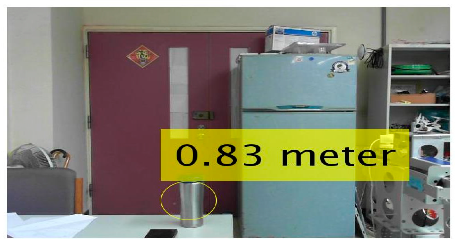
The parameters obtained after camera calibration and stereo rectification can be used to detect the object’s depth. The results of a simulation conducted to detect the distance between a robot and a mug are shown in Figure 6. The actual distance and the detected distance are both 0.83 m.
Because the camera is easily disturbed by light in a place with sunlight, such a disturbance may cause a target to be unrecognizable, or a huge database and extensive calculations may be required for target identification. Therefore, we installed an Intel Realsense D415-type depth camera on the omnidirectional wheel robot. The Intel Realsense depth camera provides a direct depth map estimation. The depth map shows different colors according to the distance, as illustrated in Figure 7. Different colors mean different distances of depth, and the distances are used in the fuzzy control of obstacle avoidance in Section 4.2.
3.3. Obstacle Detection
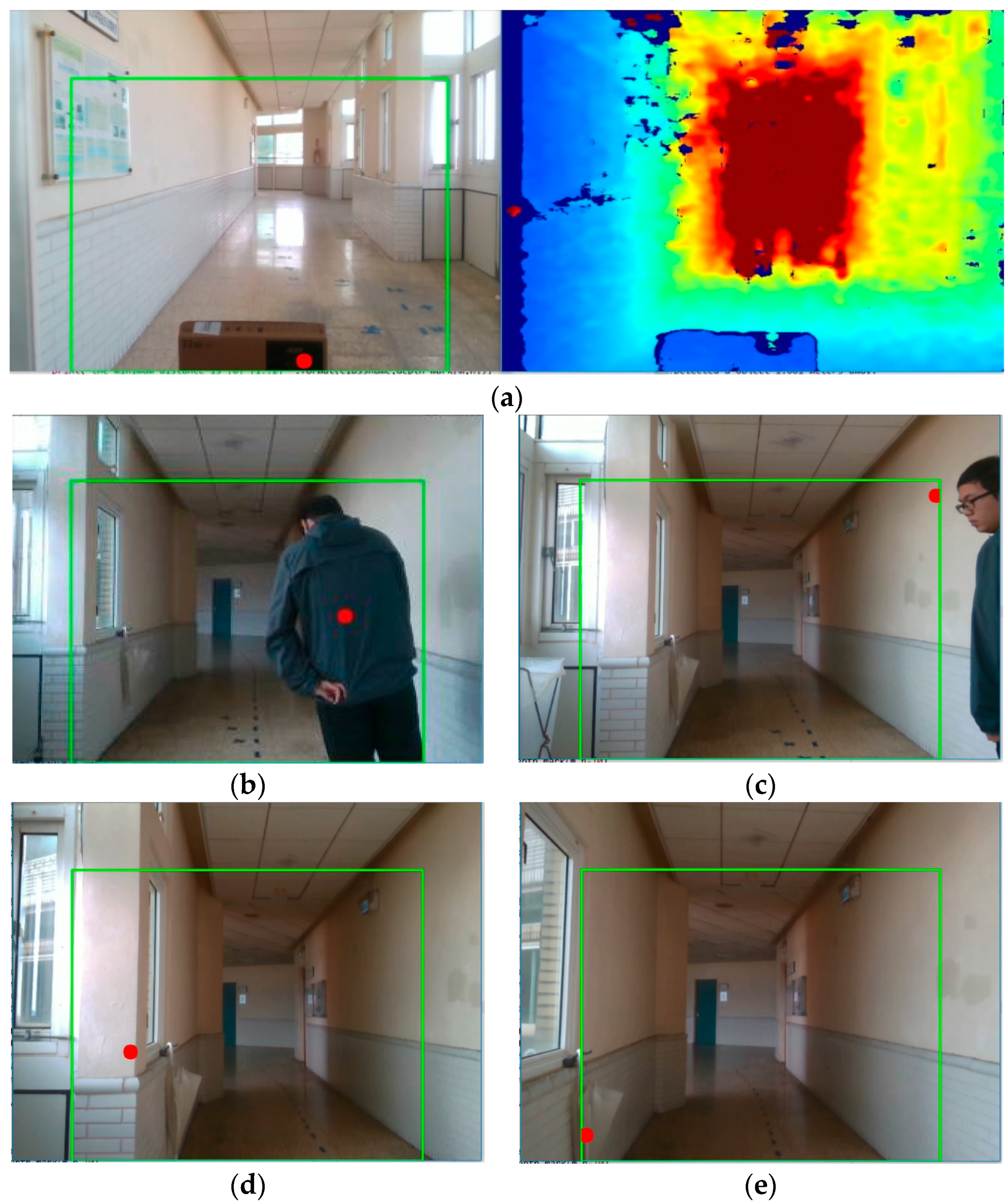
We set up a frame, as indicated by the green square in Figure 8. This frame represents the safe range of the omnidirectional WMR in terms of bumping into an obstacle. Then, we computed the distance of every pixel from the depth webcam for this frame and divided this frame into three parts (left, middle, and right) [14]. After that, we computed the minimum distance between the robot and an obstacle. Given the left distance, middle distance, and right distance, we can determine which obstacle is closer to the robot and identify the position of that obstacle.
3.4. Feature Matching
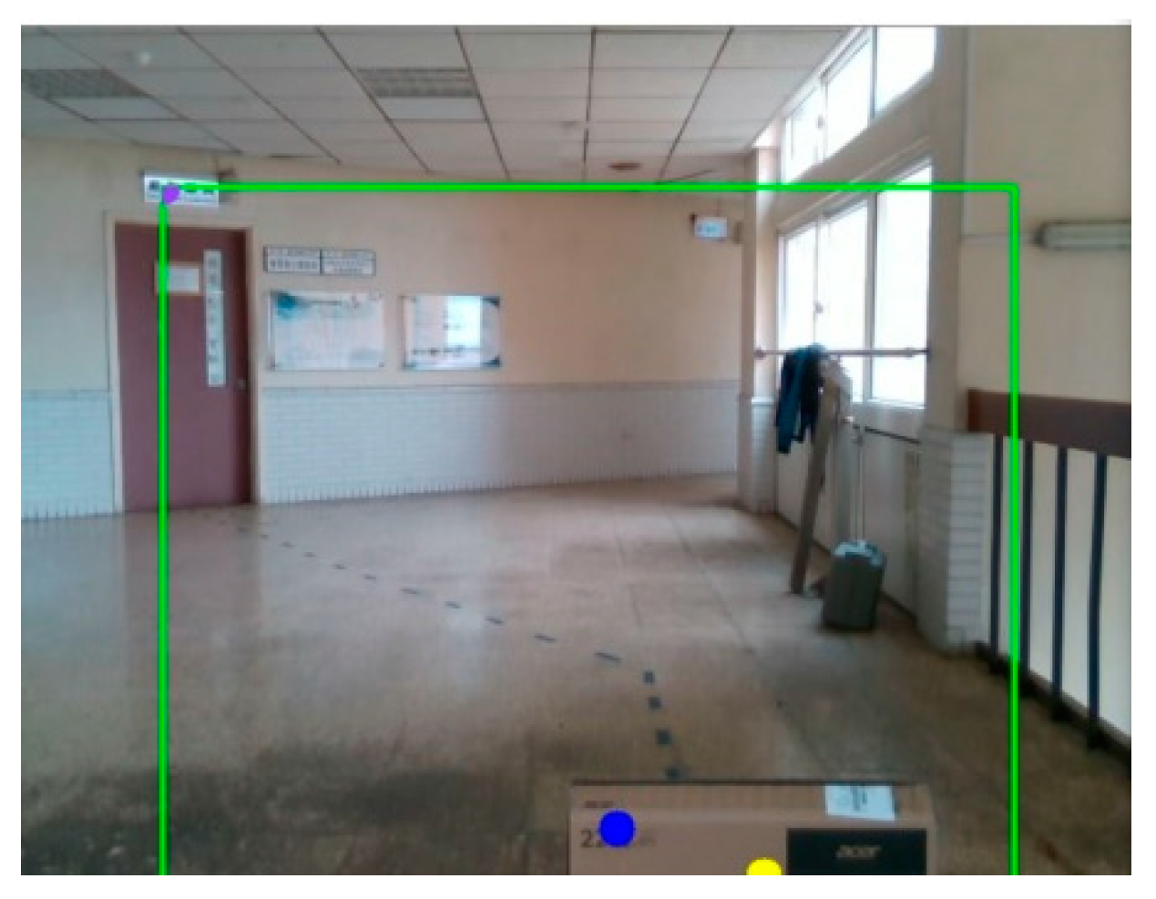
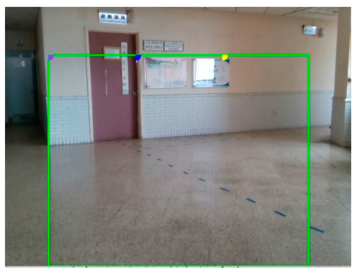
The SURF algorithm was proposed by Herbert Bay [32]. It is a robust algorithm for local feature point detection and description. The SURF algorithm is a modified version of the SIFT algorithm proposed by David Low. The SURF algorithm is faster and more efficient than the SIFT algorithm. The SURF algorithm has three main components: the extraction of local feature points, the description of feature points, and matching of feature points. We used SURF feature matching for route planning. The webcam takes pictures as the robot moves, and the pictures are matched with stored samples, which are images of the known environment. These images provide features of the environment that can help the robot with indoor navigation. We set a threshold for the feature points. When the SURF feature matching feature points exceed the threshold, they represent a proper direction or destination. The feature-matching process is shown in Figure 9.
3.5. Circular Doorknob Detection
The target doorknobs are circular. The two-stage HoughCircles transform can identify a circle in an image frame [33]. The first stage involves finding the center of a circle. Given the threshold for an image, edges can be detected, as shown in Figure 10. Then, the gradient line at each nonzero point in the edge image is identified. The greater the number of line intersection points, the greater the likelihood that they are at the center of a circle. A threshold value is set in the Hough space, which is considered the circle’s center if it exceeds the threshold value. The second stage involves detecting the radius of the circle. The Hough transform sets thresholds for the maximum and minimum radii. An object can be extracted using these thresholds, as shown in Figure 10.
4. Control Scheme
In the control system, we used LabVIEW to compile the robot system. The control method and the image processing scheme were written in Python.
4.1. Motion Control
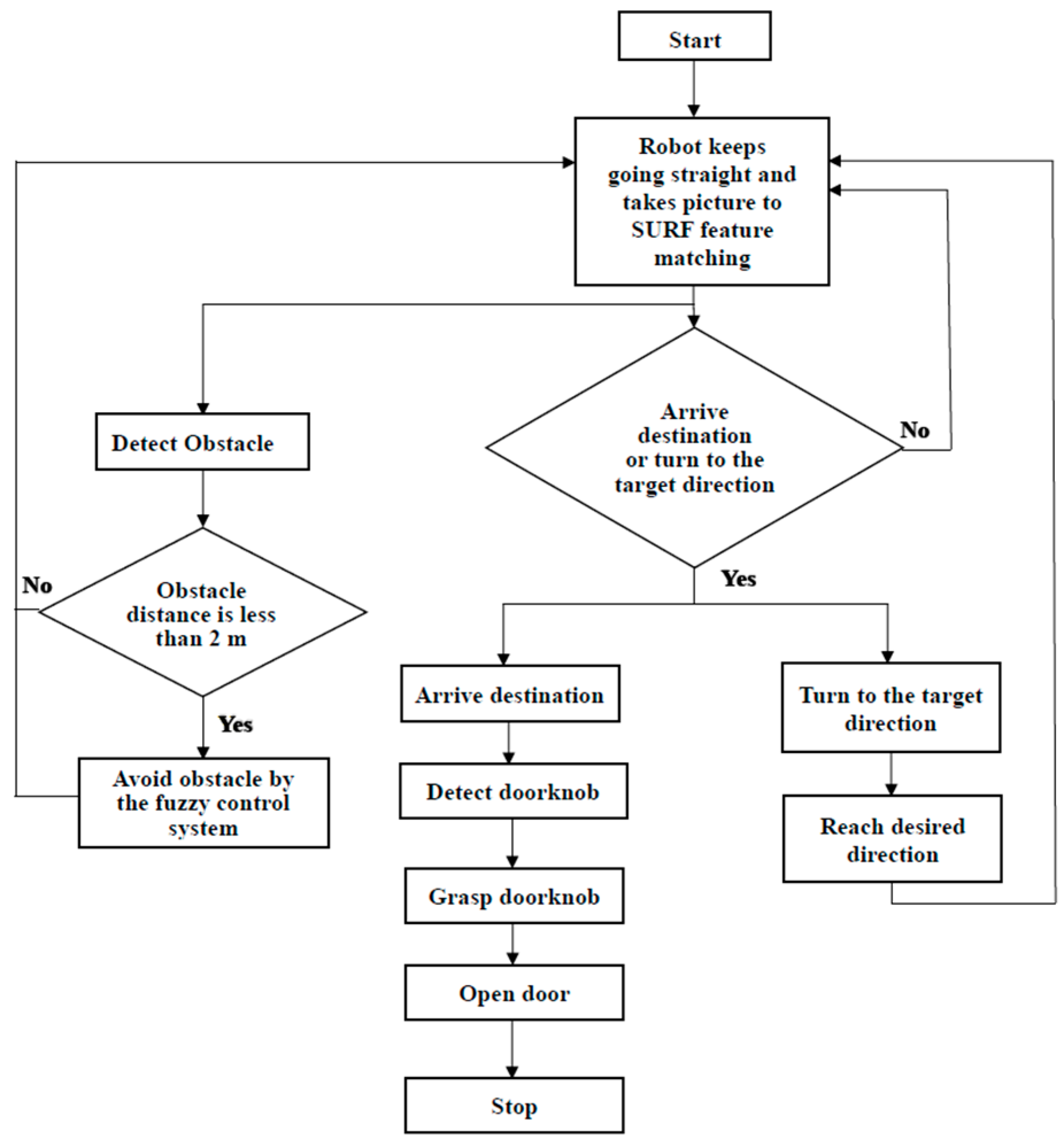
This study integrated obstacle avoidance and route navigation into the omnidirectional wheel robot. The control sequence is presented in Figure 11. The robot will follow a planned path with specified features. From the original starting point, the robot moves straight forward to the next specified feature point. When the robot reaches the desired midway point, it searches the destination point through feature matching and turns to the target’s direction. When the destination features are matched, the robot moves forward to the destination point. When the robot reaches the destination point, arm control is activated. A detailed arm control process is shown in Section 4.3. If an obstacle is found on the pathway, the robot performs obstacle avoidance control (Section 4.2), as shown in mark B in Figure 12. After avoiding the obstacle, the robot moves back to the planned path to the desired midway point before mark C in Figure 12.
After the robot begins operating, it initially uses the SURF feature-matching algorithm to determine whether it has reached a specified position. If the robot is not at the specified position, it estimates the direction to be traveled by matching the features of the SURF algorithm. The obstacle detection feature is always on during the walking process. The obstacle avoidance function is activated if obstacles are found on the path. The robot has fuzzy control installed, so the robot checks for obstacles and avoids them based on its distance from these obstacles. The experimental environment of the omnidirectional wheel robot and the predicted walking path are shown in Figure 12. When the robot arrives at the specified position, doorknob detection is initiated. After detecting the doorknob, the robot tracks the target and opens the door.
4.2. Obstacle Avoidance Control
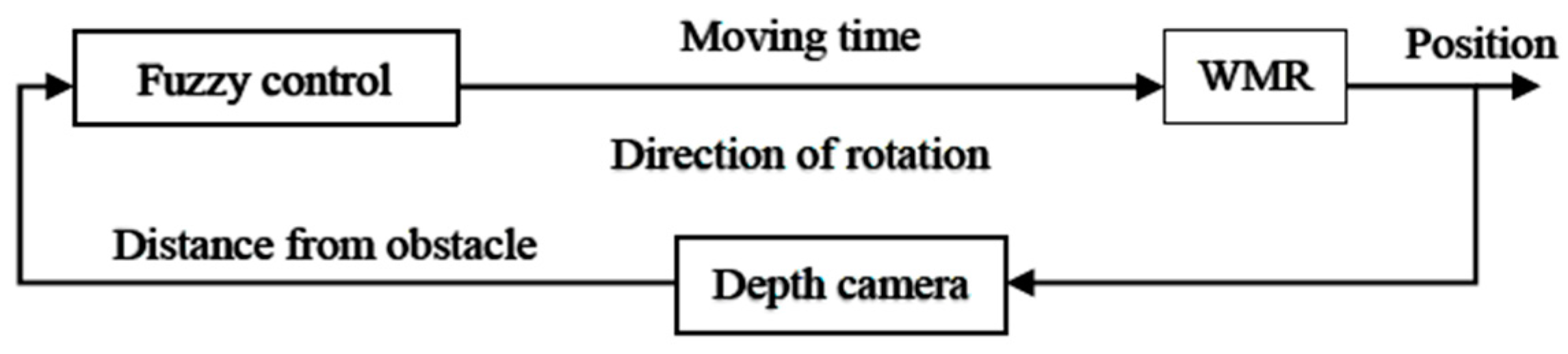
To simplify the calculation process, other than neural network mobile robot control [34,35], fuzzy control is used in obstacle avoidance to allow the robot to avoid obstacles accurately [36]. The fuzzy control of obstacle avoidance uses three inputs and two outputs. We cut the camera’s pixels into three parts: left (L), medium (M), and right (R). Each part detects the nearest obstacle and returns the distance function between the obstacle and the robot. The distances of these three obstacles are the three inputs of the fuzzy control scheme, and the fuzzy sets are near, medium, and far. The outputs are time (T) and pixel (P). The output time (T) is used to control the rotation time of the wheel, and the fuzzy sets are long (LG), medium (MD), and short (ST). The pixel (P) controls the direction of rotation. The fuzzy sets are turn_right (TR), turn_left (TL), and go_straight (TM), as shown in Figure 13, and the fuzzy control models are shown in Figure 14. The fuzzy control scheme is shown in Figure 15.
- R1: If L is near and M is near and R is near, then T is LG and P is TR.
- R2: If L is near and M is near and R is medium, then T is LG and P is TR.
- R3: If L is near and M is near and R is far, then T is LG and P is TR.
- R4: If L is near and M is medium and R is near, then T is ST and P is TM.
- R5: If L is near and M is medium and R is medium, then T is MD and P is TR.
- R6: If L is near and M is medium and R is far, then T is MD and P is TR.
- R7: If L is near and M is far and R is near, then T is ST and P is TM.
- R8: If L is near and M is far and R is medium, then T is ST and P is TR.
- R9: If L is near and M is far and R is far, then T is ST and P is TR.
- R10: If L is medium and M is near and R is near, then T is LG and P is TL.
- R11: If L is medium and M is near and R is medium, then T is LG and P is TR.
- R12: If L is medium and M is near and R is far, then T is LG and P is TR.
- R13: If L is medium and M is medium and R is near, then T is MD and P is TL.
- R14: If L is medium and M is medium and R is medium, then T is ST and P is TM.
- R15: If L is medium and M is medium and R is far, then T is ST and P is TR.
- R16: If L is medium and M is far and R is near then, T is ST and P is TL.
- R17: If L is medium and M is far and R is medium, then T is ST and P is TM.
- R18: If L is medium and M is far and R is far, then T is ST and P is TM.
- R19: If L is far and M is near and R is near, then T is LG and P is TL.
- R20: If L is far and M is near and R is medium, then T is LG and P is TL.
- R21: If L is far and M is near and R is far, then T is LG and P is TL.
- R22: If L is far and M is medium and R is near, then T is MD and P is TL.
- R23: If L is far and M is medium and R is medium, then T is MD and P is TL.
- R24: If L is far and M is medium and R is far, then T is MD and P is TL.
- R25: If L is far and M is far and R is near, then T is ST and P is TL.
- R26: If L is far and M is far and R is medium, then T is ST and P is TM.
- R27: If L is far and M is far and R is far, then T is ST and P is TM.
In Figure 12, mark A shows that when the robot detects an obstacle, it inputs the distance between the left, middle, and right to the fuzzy controller and outputs the time and direction of the rotation, as shown in mark B in Figure 12. In Figure 12, mark C shows that the robot stops at the specified position after avoiding an obstacle. When the robot arrives at the specified position, it initiates doorknob detection. The robot tracks the door after detecting the doorknob and then opens the door.
4.3. Arm Control
When the robot reaches the specified position, its arm is automatically lifted to the height of the doorknob, and the camera installed on the arm is activated to start tracking the doorknob, as shown in Figure 16. The robot determines the position of the doorknob and judges the required direction of movement [37]. The directions of movement are left rotation, right rotation, left parallel translation, and right parallel translation. We set two threshold values: the return position is greater than the threshold and lower than the threshold, and the corresponding motions are left and right translations. The times required for each right and left translation movement are 1.2 s and 900 ms, respectively. It is easy to move to the specified range. Then, the left and right rotation movements are performed to finetune the robot’s heading angle so that the robot’s arm points at the doorknob. The movement of each left and right rotation is 5°. When the robot’s position is within these two range values, the robot moves forward. When the distance from the door is shorter than the set distance, the claw of the robot’s arm grabs the doorknob and rotates. After the robot claw has turned the doorknob, it pushes the door forward and opens it.
5. Experiment Result
We placed two obstacles in front of the robot. The robot was expected to avoid all obstacles without any route planning. After detecting an obstacle, the robot estimated the direction to move, as shown in Figure 17.
When the robot is turned on, the onboard computer displays the image captured by the depth camera, as shown in Figure 18. The three circles in the picture represent the nearest left, center, and right distances, respectively. This representation makes it easy for users to identify which objects are detected by the robot. The distance and direction of the action are displayed after the obstacle detection process, as shown in Figure 18. On the depth camera image, the distances of the nearest left, middle, and right objects are greater than 2 m, so the action is GO. At the starting position, the robot does not detect any obstacles, so the control scheme sends the “go” command, which tells the robot to go straight.
Figure 19 shows the robot detecting an obstacle. Figure 20 shows that the obstacle is detected within 2 m between the middle and the right areas. After detecting the obstacle, the robot executes the fuzzy control scheme to determine the direction to move. The control scheme sends the fuzzy control result “left,” which means left rotation. After the robot rotates (Figure 21a), it will go straight and move the same distance parallel to the obstacle and then rotate back in the opposite direction (Figure 21b). The robot can avoid the obstacle successfully, as shown in Figure 21. The robot needs free space to avoid obstacles. If there is not enough space, this means the path has been blocked, and the robot will stop moving until the obstacle is removed.
After the rotation is finished (Figure 21b), the robot’s movement will be determined again. On the depth camera image (Figure 22), the distances of the nearest left, middle, and right objects are greater than 2 m, so the robot is prompted to “go straight.” The robot motion control process always uses SURF to match the target. When it matches the target, the motion control will determine the matching position and the robot’s moving direction, as shown in Figure 23 and Figure 24.
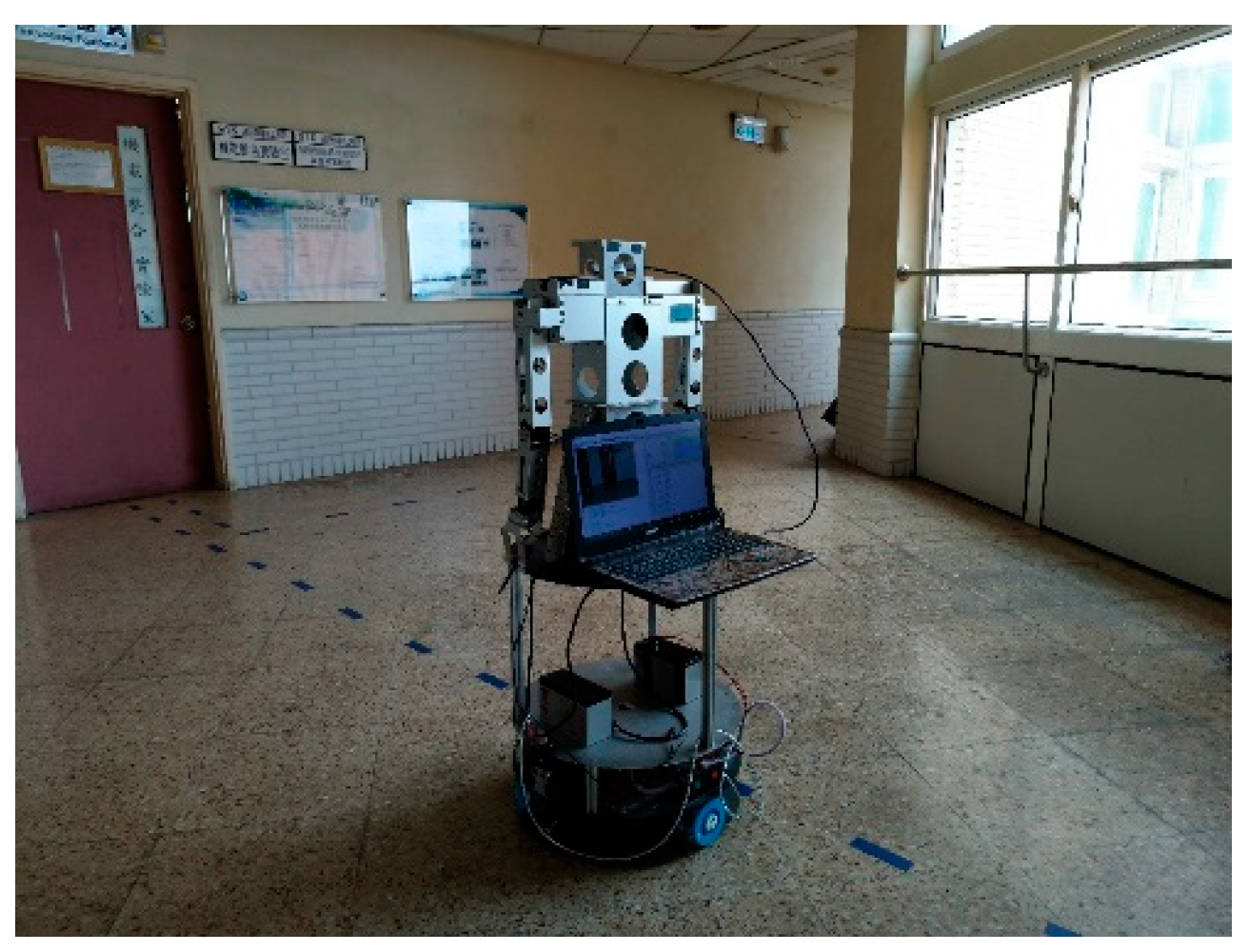
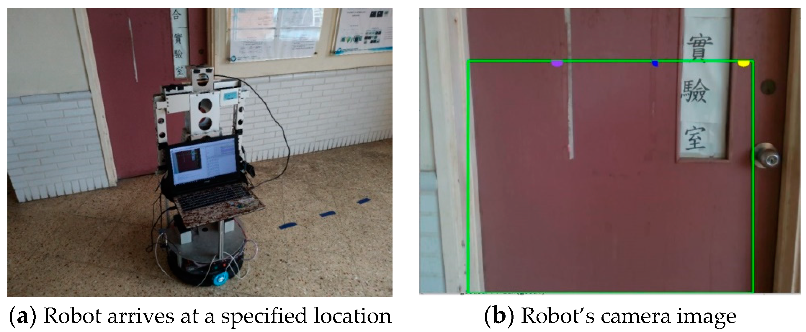
The robot’s walking process always uses SURF for target matching. When the target (predefined door) is matched, the control process shows the matching position and the robot’s movement direction. The robot moves forward to the predefined door and stops 1 m ahead of the door, as shown in Figure 25a. The robot stops moving when it arrives at the specified position. According to the image captured by the robot’s camera, the control process shows that the robot has arrived at the specified location, as shown in Figure 25b.
The arm and arm camera are activated when the robot arrives at the specified location. The arm camera starts to find the doorknob and returns the doorknob position to the robot, as shown in Figure 26. The circle center coordinate of the doorknob is indicated in Figure 26b.
When the distance between the robot and the door is shorter than the preset threshold, the robot’s claw automatically grabs the doorknob and rotates it, and the robot pushes the door forward, opens the door, and stops, as shown in Figure 27.
6. Conclusions
In this study, we proposed the use of real-time images to control the robot’s movement. The robot system has many instruments and devices installed. Some devices sense obstacles or measure the targets to be tracked. To ensure our robot was human-like, we only used cameras to make judgments regarding obstacle avoidance and navigation. The Intel Realsense depth camera was used to provide information on the surrounding object’s distance for obstacle avoidance usage. The Lifecam was used to identify target objects for doorknob detection. In terms of control, we used LabVIEW to compile the robot system. The control method and the image processing scheme were written in Python. In terms of obstacle avoidance, we used depth images to help the robot avoid obstacles, and the images were more accurate and convenient than those output by conventional ultrasonic obstacle avoidance methods. Compared with other approaches that use laser or ultrasonic sensors, determining which target the robot has detected through images is a superior method. Cameras are relatively inexpensive and easy to maintain compared to laser range finders. Image processing is also more extensive than these other approaches. A fuzzy control system was integrated into the proposed image obstacle avoidance method, and the rotation angles corresponding to different distances were different, allowing the robot to avoid multiple obstacles successfully. Most indoor navigations use SLAM to map and recognize the surroundings. In this study, we assumed the surrounding environments are known; the SURF algorithm was used to inform the robot of the position and direction of the target location. In the experiment, the robot completed actions based only on the results of image processing and recognition; in other words, similar to humans, it used only visual sensors.
Author Contributions
Conceptualization, J.-G.J.; methodology, C.-H.H.; software, C.-H.H.; validation, C.-H.H.; formal analysis, J.-G.J.; Investigation, J.-G.J.; Resources, J.-G.J.; Data curation, C.-H.H.; writing—original draft, C.-H.H.; writing—review & editing, J.-G.J.; visualization, J.-G.J.; supervision, J.-G.J.; project administration, J.-G.J.; funding acquisition, J.-G.J. All authors have read and agreed to the published version of the manuscript.
Funding
This research was funded by the Ministry of Science and Technology (Taiwan), grant number MOST 109-2221-E-019-058.
Data Availability Statement
The original contributions presented in this study are included in this article. Further inquiries can be directed to the corresponding author.
Conflicts of Interest
The authors declare no conflicts of interest.
References
- Belanche, D.; Casaló, L.V.; Flavián, C.; Schepers, J. Service robot implementation: A theoretical framework and research agenda. Serv. Ind. J. 2020, 40, 203–225. [Google Scholar] [CrossRef]
- Gonzalez-Aguirre, J.A.; Osorio-Oliveros, R.; Rodríguez-Hernández, K.L.; Lizárraga-Iturralde, J.; Menendez, R.M.; Ramírez-Mendoza, R.A.; Ramírez-Moreno, M.A.; Lozoya-Santos, J.d.J. Service Robots: Trends and Technology. Appl. Sci. 2021, 11, 10702. [Google Scholar] [CrossRef]
- Chi, L. Application of Real-Time Image Recognition and Feature Matching to Wheeled Mobile Robot for Room Service. Master’s Thesis, National Taiwan Ocean University, Keelung City, Taiwan, 2018. [Google Scholar]
- Najim, H.A.; Kareem, I.S.; Abdul-Lateef, W.E. Design and Implementation of an Omnidirectional Mobile Robot for Medi-cine Delivery in Hospitals during the COVID-19 Epidemic. AIP Conf. Proc. 2023, 2830, 070004. [Google Scholar]
- Bernardo, R.; Sousa, J.M.C.; Botto, M.A.; Gonçalves, P.J.S. A Novel Control Architecture Based on Behavior Trees for an Omni-Directional Mobile Robot. Robotics 2023, 12, 170. [Google Scholar] [CrossRef]
- Palacín, J.; Rubies, E.; Clotet, E.; Martínez, D. Evaluation of the Path-Tracking Accuracy of a Three-Wheeled Omnidirectional Mobile Robot Designed as a Personal Assistant. Sensors 2021, 21, 7216. [Google Scholar] [CrossRef] [PubMed]
- Jia, Q.; Wang, M.; Liu, S.; Ge, J.; Gu, C. Research and development of mecanum-wheeled omnidirectional mobile robot implemented by multiple control methods. In Proceedings of the 23rd International Conference on Mechatronics and Machine Vision in Practice, Nanjing, China, 28–30 November 2016. [Google Scholar]
- Park, S.; Ryoo, Y.; Im, D. Fuzzy Steering Control of Three-Wheels Based Omnidirectional Mobile Robot. In Proceedings of the International Conference on Fuzzy Theory and Its Applications, Taichung, Taiwan, 9–11 November 2016. [Google Scholar]
- Chung, J.H.; Yi, B.-J.; Kim, W.K.; Lee, H. The dynamic modeling and analysis for an omnidirectional mobile robot with three caster wheels. In Proceedings of the IEEE International Conference on Robotics and Automation, Taipei, Taiwan, 14–19 September 2003. [Google Scholar]
- Ruan, X.; Li, W. Ultrasonic sensor based two-wheeled self-balancing robot obstacle avoidance control system. In Proceedings of the IEEE International Conference on Mechatronics and Automation, Tianjin, China, 3–6 August 2014. [Google Scholar]
- Jin, Y.; Li, S.; Li, J.; Sun, H.; Wu, Y. Design of an Intelligent Active Obstacle Avoidance Car Based on Rotating Ultrasonic Sensors. In Proceedings of the IEEE 8th Annual International Conference on CYBER Technology in Automation, Control, and Intelligent Systems, Tianjin, China, 19–23 July 2018. [Google Scholar]
- Peng, Y.; Qu, D.; Zhong, Y.; Xie, S.; Luo, J. The Obstacle Detection and Obstacle Avoidance Algorithm Based on 2-D Lidar. In Proceedings of the IEEE International Conference on Information and Automation, Lijiang, China, 8–10 August 2015. [Google Scholar]
- Wang, T.; Bu, L.; Huang, Z. A new method for obstacle detection based on Kinect depth image. In Proceedings of the Chinese Automation Congress, Wuhan, China, 27–29 November 2015. [Google Scholar]
- Hamzah, R.A.; Rosly, H.N.; Hamid, S. An Obstacle Detection and Avoidance of a Mobile Robot with Stereo Vision Camera. In Proceedings of the International Conference on Electronic Devices, Systems and Applications, Kuala Lumpur, Malaysia, 25–27 April 2011. [Google Scholar]
- Sharifi, M.; Chen, X. Introducing a novel vision based obstacle avoidance technique for navigation of autonomous mobile robots. In Proceedings of the IEEE 10th Conference on Industrial Electronics and Applications, Auckland, New Zealand, 15–17 June 2015. [Google Scholar]
- AI-Jubouri, Q.; AI-Nuaimy, W.; AI-Taeeand, M.; Young, I. Recognition of Individual Zebrafish Using Speed-Up Robust Feature Matching. In Proceedings of the 10th International Conference on Developments in eSystems Engineering, Paris, France, 14–16 June 2017. [Google Scholar]
- Sheu, J.-S.; Tsai, W.-H. Implementation of a following wheel robot featuring stereoscopic vision. Multimed. Tools Appl. 2017, 76, 25161–25177. [Google Scholar] [CrossRef]
- Tsai, C.-Y.; Nisar, H.; Hu, Y.-C. Mapless LiDAR Navigation Control of Wheeled Mobile Robots Based on Deep Imitation Learning. IEEE Access 2021, 9, 117527–117541. [Google Scholar] [CrossRef]
- Li, C.; Wang, S.; Zhuang, Y.; Yan, F. Deep Sensor Fusion between 2D Laser Scanner and IMU for Mobile Robot Localization. IEEE Sens. J. 2019, 21, 8501–8509. [Google Scholar] [CrossRef]
- Intel Realsense Depth Camera D415. Available online: https://www.intel.com/content/www/us/en/products/sku/128256/intel-realsense-depth-camera-d415/specifications.html (accessed on 21 January 2019).
- Pin, F.; Killough, S. A new family of omnidirectional and holonomic wheeled platforms for mobile robots. IEEE Trans. Robot. Autom. 1994, 10, 480–489. [Google Scholar] [CrossRef]
- Purwin, O.; D’andrea, R. Trajectory generation and control for four wheeled omnidirectional vehicles. Robot. Auton. Syst. 2006, 54, 13–22. [Google Scholar] [CrossRef]
- Zhong, Q.H. Using Omni-Directional Mobile Robot on Map Building Application. Master’s Thesis, National Cheng Kung University, Tainan City, Taiwan, 2009. [Google Scholar]
- Arduino Uno R3. Available online: https://electricarena.blogspot.com/ (accessed on 10 January 2019).
- DFRduino IO Expansion Shield for Arduino. Available online: https://www.dfrobot.com/product-1009.html (accessed on 15 March 2019).
- Omni Wheel. Available online: http://www.kornylak.com/ (accessed on 15 March 2019).
- Color Space. Available online: https://en.wikipedia.org/wiki/Color_space (accessed on 20 April 2019).
- Dragoi, V. Chapter 14: Visual—Eye and Retina. Neurosci. Online. 2020. Available online: https://nba.uth.tmc.edu/neuroscience/m/s2/chapter14.html (accessed on 20 April 2019).
- Color Cube. Available online: https://cs.vt.edu/Undergraduate/courses.html (accessed on 20 April 2019).
- Zhang, Y.; Xu, X.; Dai, Y. Two-Stage Obstacle Detection Based on Stereo Vision in Unstructured Environment. In Proceedings of the Sixth International Conference on Intelligent Human-Machine Systems and Cybernetics, Hangzhou, China, 26–27 August 2014. [Google Scholar]
- Zhang, Z. A Flexible New Technique for Camera Calibration. Available online: https://www.microsoft.com/en-us/research/wp-content/uploads/2016/02/tr98-71.pdf (accessed on 20 January 2019).
- Bay, H.; Tuytelaars, T.; Gool, L.V. Speed Up Robust Features. In Proceedings of the European Conference on Computer Vision, Graz, Austria, 7–13 May 2006. [Google Scholar]
- Liu, H.; Qian, Y.; Lin, S. Detecting Persons Using Hough Circle Transform in Surveillance Video. In Proceedings of the International Conference on Computer Vision Theory and Applications, Angers, France, 17–21 May 2010. [Google Scholar]
- Fang, W.; Chao, F.; Yang, L.; Lin, C.-M.; Shang, C.; Zhou, C.; Shen, Q. A recurrent emotional CMAC neural network controller for vision-based mobile robots. Neurocomputing 2019, 334, 227–238. [Google Scholar] [CrossRef]
- Wu, Q.; Lin, C.-M.; Fang, W.; Chao, F.; Yang, L.; Shang, C.; Zhou, C. Self-Organizing Brain Emotional Learning Controller Network for Intelligent Control System of Mobile Robots. IEEE Access 2018, 6, 59096–59108. [Google Scholar] [CrossRef]
- Chao, C.H.; Hsueh, B.Y.; Hsiao, M.Y.; Tsai, S.H.; Li, T.H.S. Real-Time Target Tracking and Obstacle Avoidance for Mobile Robots using Two Cameras. In Proceedings of the ICROS-SICE International Joint Conference, Fukuoka, Japan, 18–21 August 2009. [Google Scholar]
- Su, H.-R.; Chen, K.-Y. Design and Implementation of a Mobile Robot with Autonomous Door Opening Ability. Int. J. Fuzzy Syst. 2019, 21, 333–342. [Google Scholar] [CrossRef]
Figure 1.
The primary devices of the proposed robot system are (a) a mobile robot; (b) an omnidirectional wheel, battery, and control components; and (c) an Intel Realsense depth camera.
Figure 1.
The primary devices of the proposed robot system are (a) a mobile robot; (b) an omnidirectional wheel, battery, and control components; and (c) an Intel Realsense depth camera.

Figure 2.
(a) Omnidirectional wheel structure. (b) Coordinate system.

Figure 3.
(a) Arduino Uno R3 [15], (b) DFRduino IO Expansion board, and (c) Microsoft LifeCam.
Figure 3.
(a) Arduino Uno R3 [15], (b) DFRduino IO Expansion board, and (c) Microsoft LifeCam.

Figure 4.
Zhang Zhengyou camera calibration samples.

Figure 5.
Stereo rectification.

Figure 6.
Mug distance.

Figure 7.
(a) is the original image, (b) is the depth image where the blue color means the object is near to the camera, and dark red means the object is far from the camera. The distance ranges from 0 m (dark blue) to 8 m (dark red).
Figure 7.
(a) is the original image, (b) is the depth image where the blue color means the object is near to the camera, and dark red means the object is far from the camera. The distance ranges from 0 m (dark blue) to 8 m (dark red).

Figure 8.
Detection of different obstacles: (a) obstacle detection and obstacle depth map, (b) nearest obstacle point is on the right side, (c) move to the left and the obstacle is outside the safe frame, (d) nearest obstacle point is on the left side, (e) move to the right and the moving direction is clear.

Figure 9.
SURF matching: (a) robot is heading in the right direction, (b) robot is heading in the wrong direction, (c) robot is heading in the right direction.
Figure 9.
SURF matching: (a) robot is heading in the right direction, (b) robot is heading in the wrong direction, (c) robot is heading in the right direction.

Figure 10.
Edge detection uses a threshold, and the doorknob is detected; the Chinese character on the left part of the figure is the room’s name.
Figure 10.
Edge detection uses a threshold, and the doorknob is detected; the Chinese character on the left part of the figure is the room’s name.

Figure 11.
Control flowchart.

Figure 12.
Robot moving path.

Figure 13.
The fuzzy sets of the three inputs are near (blue), medium (red), and far (yellow); the fuzzy sets of the output pixel are turn_left (blue), go_straight (red), and turn_right (yellow); the fuzzy sets of the output time are short (blue), medium (red), and long (yellow).
Figure 13.
The fuzzy sets of the three inputs are near (blue), medium (red), and far (yellow); the fuzzy sets of the output pixel are turn_left (blue), go_straight (red), and turn_right (yellow); the fuzzy sets of the output time are short (blue), medium (red), and long (yellow).

Figure 14.
Fuzzy control model where the yellow color means large value and the dark blue means small value.
Figure 14.
Fuzzy control model where the yellow color means large value and the dark blue means small value.

Figure 15.
Fuzzy control scheme.

Figure 16.
The robot arm lifts to the specified height; the Chinese characters on the figure are the room’s name.
Figure 16.
The robot arm lifts to the specified height; the Chinese characters on the figure are the room’s name.

Figure 17.
Robot obstacle avoidance test.

Figure 18.
On the depth camera image, the distances of the nearest left, middle, and right objects are greater than 2 m, so the action is GO.
Figure 18.
On the depth camera image, the distances of the nearest left, middle, and right objects are greater than 2 m, so the action is GO.

Figure 19.
Robot’s starting position.

Figure 20.
The robot finds an obstacle as the blue mark (in the middle area) and yellow mark (in the right area) on the picture, and the distances are 1.65 m and 1.62 m, respectively; the action is a LEFT turn.
Figure 20.
The robot finds an obstacle as the blue mark (in the middle area) and yellow mark (in the right area) on the picture, and the distances are 1.65 m and 1.62 m, respectively; the action is a LEFT turn.

Figure 21.
Robot avoids obstacle (box).

Figure 22.
Image on the robot’s depth camera.

Figure 23.
(a) The robot reaches the midway point; (b) the robot’s image.

Figure 24.
After the SURF matching, the robot turns to the target direction and moves forward.

Figure 25.
(a) The robot arrives at the specified location; (b) the Chinese characters on the figure are the room’s name.
Figure 25.
(a) The robot arrives at the specified location; (b) the Chinese characters on the figure are the room’s name.

Figure 26.
(a) Doorknob detection, Activate arm and arm’s camera; (b) the Chinese characters on the figure are the room’s name. Arm’s camera image; the object distance is 0.827 m, and the coordinate is (436.5, 51.5).
Figure 26.
(a) Doorknob detection, Activate arm and arm’s camera; (b) the Chinese characters on the figure are the room’s name. Arm’s camera image; the object distance is 0.827 m, and the coordinate is (436.5, 51.5).

Figure 27.
The robot opens the door; the Chinese characters on the figure are the room’s name.

Disclaimer/Publisher’s Note: The statements, opinions and data contained in all publications are solely those of the individual author(s) and contributor(s) and not of MDPI and/or the editor(s). MDPI and/or the editor(s) disclaim responsibility for any injury to people or property resulting from any ideas, methods, instructions or products referred to in the content. |
© 2024 by the authors. Licensee MDPI, Basel, Switzerland. This article is an open access article distributed under the terms and conditions of the Creative Commons Attribution (CC BY) license (https://creativecommons.org/licenses/by/4.0/).
Share and Cite
MDPI and ACS Style
Hsu, C.-H.; Juang, J.-G. Using a Robot for Indoor Navigation and Door Opening Control Based on Image Processing. Actuators 2024, 13, 78. https://0-doi-org.brum.beds.ac.uk/10.3390/act13020078
AMA Style
Hsu C-H, Juang J-G. Using a Robot for Indoor Navigation and Door Opening Control Based on Image Processing. Actuators. 2024; 13(2):78. https://0-doi-org.brum.beds.ac.uk/10.3390/act13020078
Chicago/Turabian StyleHsu, Chun-Hsiang, and Jih-Gau Juang. 2024. "Using a Robot for Indoor Navigation and Door Opening Control Based on Image Processing" Actuators 13, no. 2: 78. https://0-doi-org.brum.beds.ac.uk/10.3390/act13020078
Note that from the first issue of 2016, this journal uses article numbers instead of page numbers. See further details here.