Fractional-Order Surge Control of Active Magnetic Bearings Suspended Compressor


1
Department of Electrical Engineering, Royal Thai Air Force Academy, 171/1 Phaholyothin Rd., Saimai, Bangkok 10220, Thailand
2
Charles L. Brown Department of Electrical and Computer Engineering, University of Virginia, Charlottesville, VA 22904-4743, USA
*
Authors to whom correspondence should be addressed.
†
These authors contributed equally to this work.
Actuators 2020, 9(3), 75; https://0-doi-org.brum.beds.ac.uk/10.3390/act9030075
Submission received: 7 July 2020
/
Revised: 2 August 2020
/
Accepted: 20 August 2020
/
Published: 24 August 2020
(This article belongs to the Special Issue Feature Papers to Celebrate the SCIE Coverage)
Abstract
: surge control in centrifugal compressors by using active magnetic bearings (AMBs) has been successfully designed and implemented. However, the structure and design process of surge control are quite complex. This paper reports on the design and implementation of fractional-order proportional-derivative control (FOPD) that results in the required specifications of surge control with a simple controller structure. To validate its effectiveness, the proposed FOPD surge controller has been implemented on a centrifugal compressor test rig equipped with AMBs. Simulation and experimental results show that the FOPD surge controller outperforms integer-order PD (IOPD) control in extending the surge limit in terms of the mass flow and provides similar performance as the controller.
1. Introduction
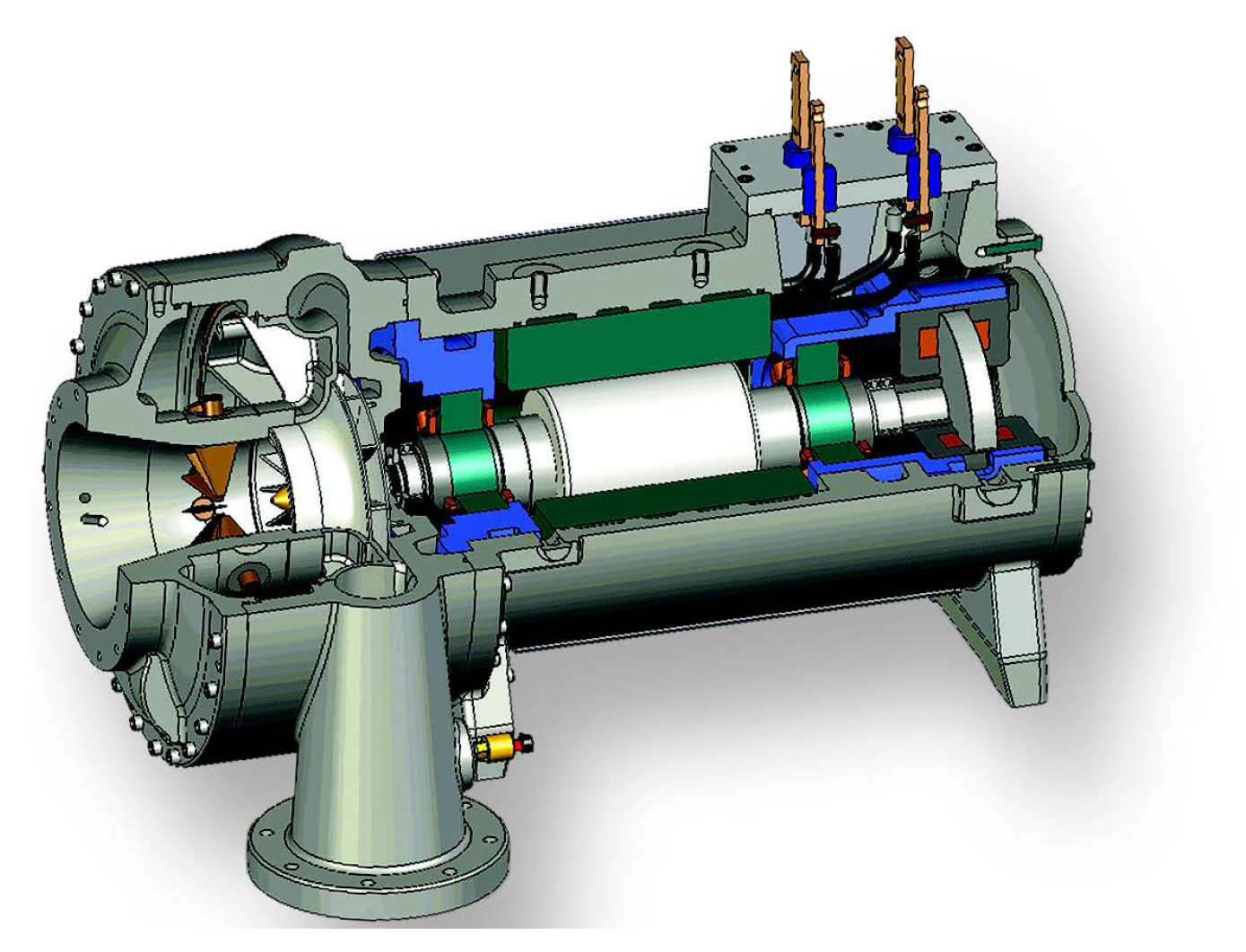
Active magnetic bearings (AMBs) have increasingly been used in compressor applications because they provide higher performance and reliability. An example of a compressor equipped with magnetic bearings is shown in Figure 1. So far, AMBs have been applied to compressor applications mainly to improve performance of the system, with two approaches. The first approach is to use AMBs to support the rotor instead of the traditional bearings. This technology has been applied to compressors in industrial applications for more than two decades [1]. The second approach, which is in the research stage but shows the effectiveness of AMB usage in compressors, is to control the instability in the compression system, referred to as surge.
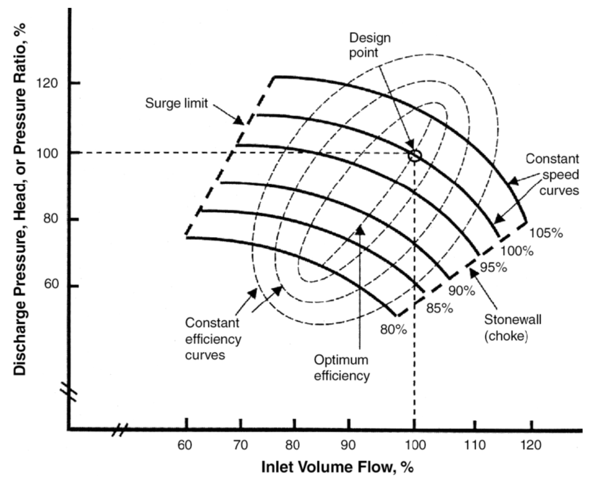
The rotor of the compressor is levitated by magnetic forces and is allowed to rotate with no mechanical contact and friction losses. Consequently, the maintenance cost is low because there are almost no consumable components and no lubrication is required. Moreover, AMBs have an active control capability which keeps the rotor near the clearance center during operation. This capability of AMBs helps compressors to operate efficiently at high rotational speeds. The performance of a compressor is affected not only by the rotor suspension mechanism, but also the stability of the compression system. The information of compressor characteristics and efficiency is elucidated in the compressor characteristic curve, as shown in Figure 2.
This map provides all possible operating points of a compressor in terms of mass flow rate, pressure ratio, and rotational speed. Moreover, it also indicates the border between stable and unstable regions of compressor operation, referred to as the surge line. When the flow is reduced below the surge limit, the pressure at the discharge of the compressor exceeds the pressure generation capability of the compressor, causing a momentary reversal of flow. When this flow reversal occurs, the pressure of the discharge system is reduced, allowing the compressor to resume delivering flow until the discharge pressure again increases, and this surge cycle repeats. Prolonged operation in this unstable mode can cause serious mechanical damage to the compressor.
There are two main techniques used to address the surge phenomenon. The first technique is surge avoidance, which is the prevention of operation at or near the surge limit. The surge avoidance line is placed in parallel to and on the right-hand side of the surge limit line. The separation between the surge limit line and the surge avoidance line is called surge margin. This margin varies between 10% and 25%, depending on how critical operation safety is. Whenever the compressor’s flow reduces and reaches the surge avoidance line, an antisurge mechanism will try to increase the flow and bring the operating point of the compressor back to the right-hand side of the surge avoidance line. The antisurge mechanisms commonly used are blow-off valves and bleed valves. When these valves are opened, the pressure buildup in the compressor is released and the mass flow rate increases. The surge avoidance technique is easy and practical to implement, but this avoidance prevents the compressor from operating in the high-pressure region, which limits the performance of the compressor. More details on the surge avoidance technique can be found in [4].
The second technique is surge suppression and control. The objective of this technique is to increase the efficiency of compressors by allowing for operation closer to and beyond the surge limit line and to increase the range of mass flow where a compressor can operate stably. This technique can be achieved in both passive and active ways. The most common approach for a passive method is to vary the plenum volume by a spring-mass-damper system. This mechanism will induce a pressure variation in the compression system in order to extend the stable flow region. An example of a passive surge controller can be found in [5]. On the other hand, active surge controllers use actuators along with feedback flow and pressure measurements by sensors. One of the challenges of the active surge control method is choosing the proper actuator. The most widely used actuator for active surge control is a throttle valve at the system exhaust. In [6], a throttle valve was used as an actuator to stabilize the flow in the compressor with the measurement of plenum pressure. The results from the study show that a throttle valve stabilizes the system effectively in the low speed range, but the performance degrades in the high speed range due to the bandwidth and mechanical limitations of the actuator.
Recently, AMBs have been demonstrated as a servo actuator for surge control. The motivation to use AMBs came from a study by Senoo and Ishida in [7], which shows that the clearance between an impeller tip and a shroud has a strong impact on the flow characteristics of a compressor. The use of AMBs to control the impeller tip clearance in a high-speed centrifugal compressor was proposed by Sanadgol in [8]. The variation of the impeller tip clearance induces a pressure variation that is used to control the surge. The work by Sanadgol was limited to simulation study. Later, Yoon et al. [9] further developed and successfully implemented the method proposed by Sanadgol, and the results showed that the surge controller can stabilize the compression system with the compressor running at up to 16,000 rpm.
One of the key components for an AMB system is the controller. Most of controllers that have been used in AMB systems are Proportional-Integral-Derivative (PID) due to their components having an intuitive physical meaning, i.e., damping and stiffness, which makes them easy to tune. However, the desired performance of a system is sometimes not satisfied by using PID controllers, especially in a complex system such as AMBs. Thus, advanced controllers—which are typically of higher orders—are used instead. Despite better performance and stronger robustness to AMB systems than the PID controller they result in, these advanced controllers are more complicated to design and are typically of higher orders. As a result, they are rarely used in industry. There is clearly strong motivation to strike a balance between the simplicity of a PID controller and the high performance of a more complicated advanced controller.
One idea to achieve this trade-off is to apply fractional-order calculus theory to the controller design. The fractional-order control has been applied to many applications due to its simple structure and its capability to represent high-order processes. A relevant work that studied and implemented fractional-order control on AMB systems was demonstrated in [10], where a fractional-order PID (FOPID) controller was applied to the rotor suspension by using radial and thrust AMBs. The work reported on in this paper is the design of and implementation of FOPD controllers for surge control of the AMBs suspended centrifugal compressor test rig, whose suspension has been achieved by FOPID control in [10].
The organization of the reminder of the paper is as follows. First, an overview of the centrifugal compressor test rig and the compression system are introduced. After that, the fractional-order surge controller design and analysis is explained. The designed surge controller is then validated by the simulation and experiments. Lastly, the results and comparison of the designed surge controller are concluded.
2. System Description and Modeling
2.1. Description of the Test Rig
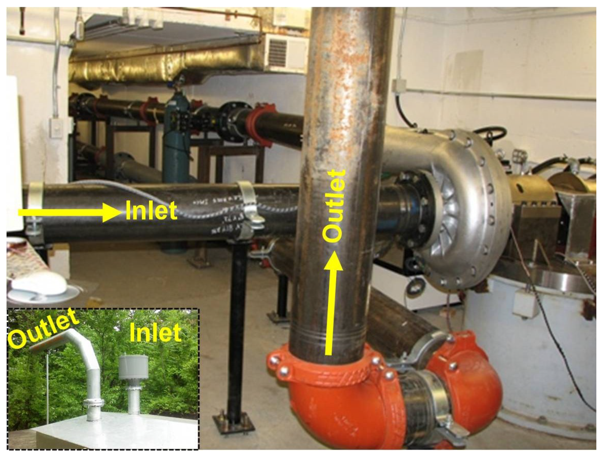
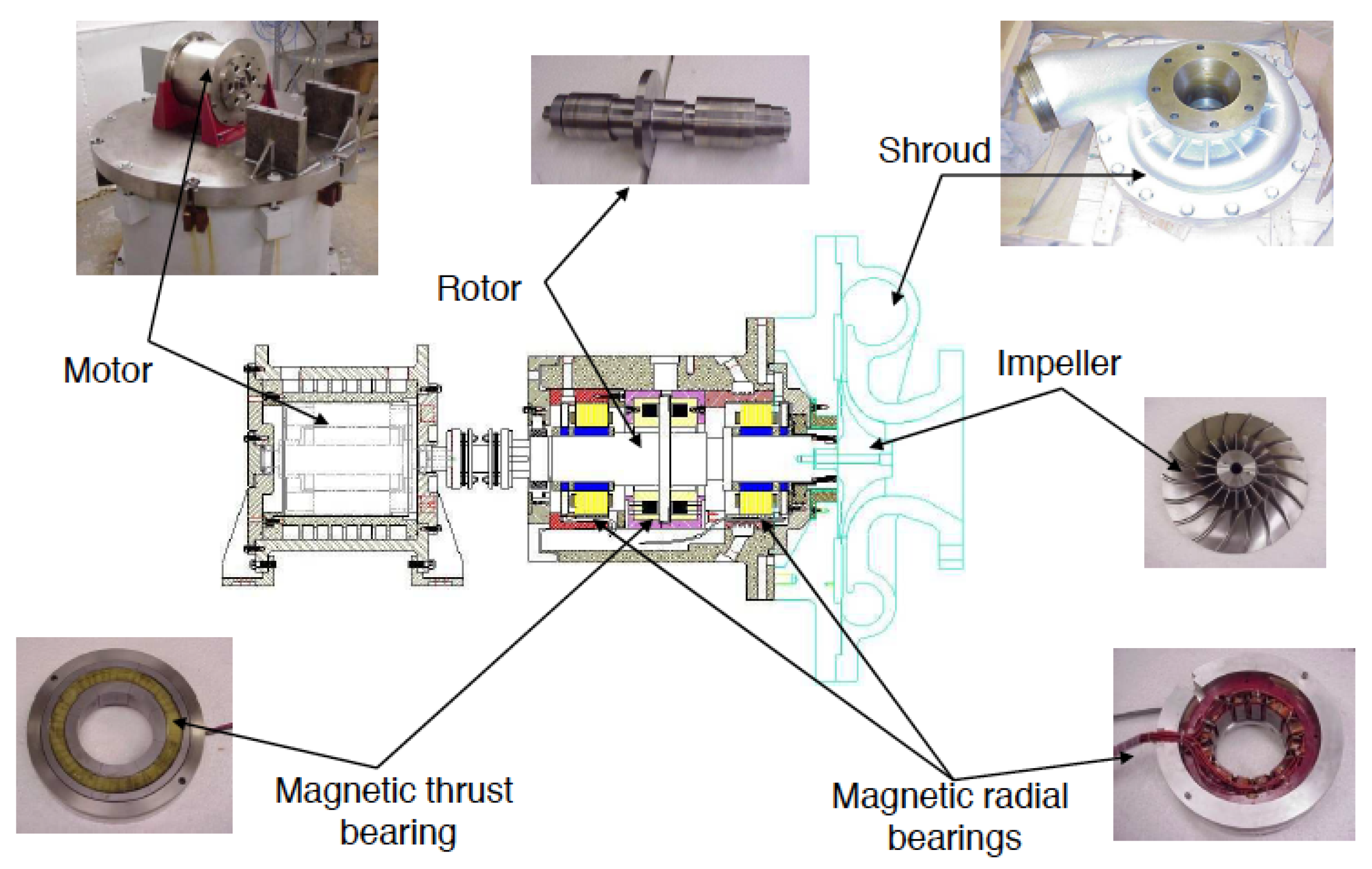
In order to validate the design and implementation of the proposed FOPD controller for surge control in the centrifugal compressor, the compressor test rig equipped with AMBs—shown in Figure 3 and Figure 4—was built in the Rotating Machinery and Control Laboratory (ROMAC) at the University of Virginia. The rotor of the compressor is supported by two radial AMBs. Moreover, the axial AMB was designed to modulate the impeller tip clearance of the compressor to control compressor surge control. The maximum rotating speed is about 23,000 rpm. The properties of the radial and axial AMBs and the properties of the instrumentation are summarized in Table 1 and Table 2, respectively.
2.2. Compression System
2.2.1. Components
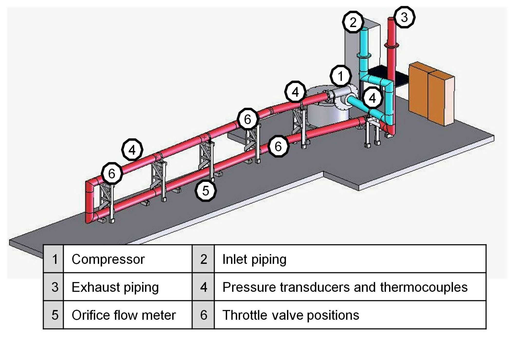
The compression system consists of three main components, the centrifugal compressor, the modular ducting system, and the throttle valve. The location of each component installed in the system is illustrated in Figure 5.
- Centrifugal compressor: The compressor is a single stage with an unshrouded impeller as shown in Figure 4. It was manufactured and donated by Kobe Steel, Ltd., Japan. The compressor design parameters are summarized in Table 3. For this compressor, the impeller tip clearance, which is the axial clearance between the static shroud and the impeller tip, is regulated by the thrust AMB.
- Throttle valve: Along the pipeline, the throttle valve is installed (with three possible locations, as shown in Figure 5), to control the steady state flow rate. Changes in the flow rate will change the volume in the plenum. These throttle valves are common, commercially available butterfly-type valves.
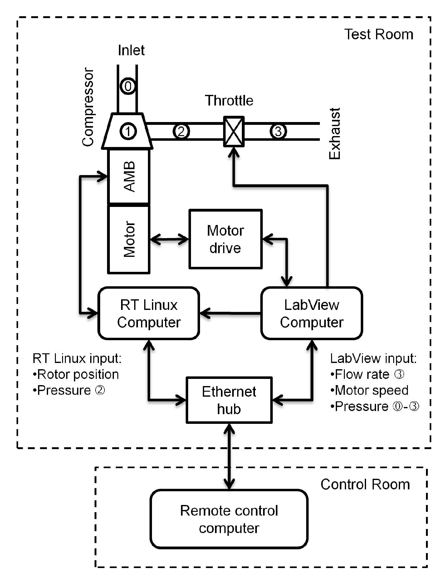
Pressure transducers, thermocouples, and orifice flow meters are installed in the compression system in order to measure the pressure, temperature, and mass flow rate, respectively. The locations of these sensors can be found in Figure 5. These measurements will be used to generate the compressor characteristic curve as well as to provide information for the surge controller. Additionally, the compressor is driven by an induction motor with an output power of 125 kW at the maximum speed of 29,680 rpm. Due to the high power density of the motor, a cooling system is required when operating continuously at high speeds. Therefore, a chiller is installed to circulate the refrigerant fluid in the cooling system of the motor. In addition, rotor suspension and surge control algorithms are implemented by the computer operating on a real-time RTLinux operating system, with a sampling rate of 5 kHz. Input signals to the control computer include rotor position measurements from sensors and the plenum pressure rise measurement, which are sampled at the same time interval. The temperature and flow measurements are collected by the Labview data acquisition system, which is used to operate the motor drive and throttle valve as well. For the user’s safety, these two computers can be controlled remotely from a control room separated from the compressor test rig. The layout drawing of the control/data-acquisition system is illustrated in Figure 6.
2.2.2. Compression System Modeling
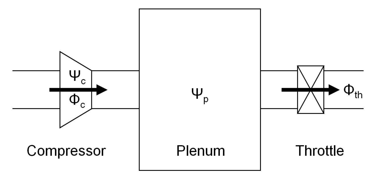
To design the surge controller, a model that describes the flow instabilities in the compression system is required. The well-known, one-dimensional compression model was derived by Greitzer in [11]. Greitzer’s model describes the flow of fluid through the compressor, the plenum volume, and the throttle valve, as shown in Figure 7. The nondimensional states of the compression system are the compressor mass flow rate , the compressor pressure rise , the plenum pressure rise , and the throttle mass flow rate .
In [8], the effect of the impeller tip clearance was studied and the nondimensional compressor pressure rise was derived as a function of the nondimensional steady-state compressor pressure and the variation of the impeller tip clearance. However, Greitzer’s compression model does not capture the effect of the pipeline, which might cause additional resonances in the system characteristics. Therefore, an enhanced model of the compression system that includes the pipeline dynamics of this test rig was derived in [9].
The overall compression system equations are assembled as
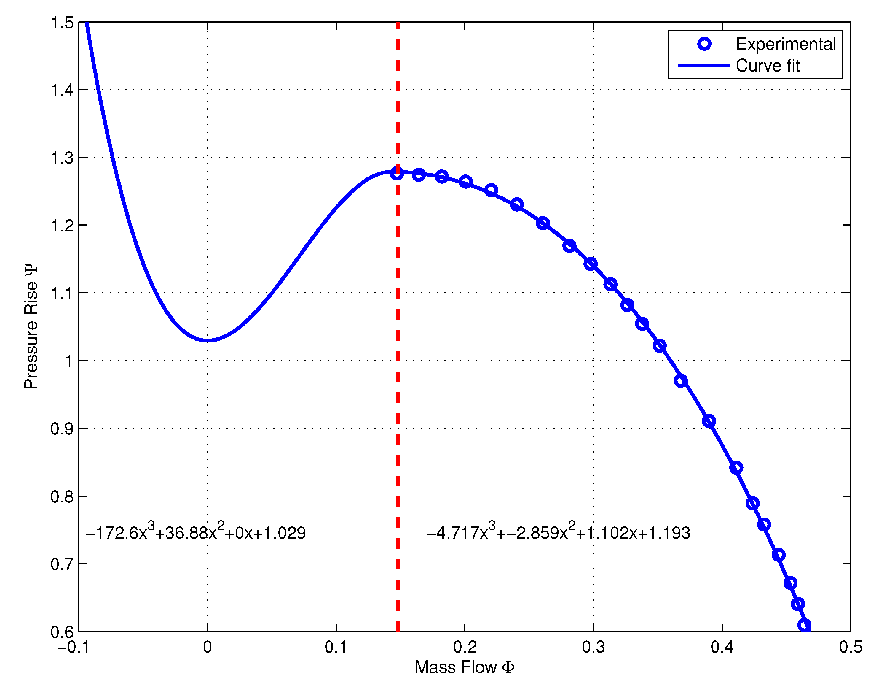
where Equations (1a) and (1b) describe the compressor dynamics with the linearized impeller tip clearance effect, and Equations (1c) and (1d) represent the pipeline dynamics. The definitions of the coefficient matrices of the pipeline , , , , and and the complete derivation of the overall compression system equations can be found in [9]. All relevant parameters that appear in the overall compression system equations can be found in Table 5. In addition, the characteristic curve coefficients , , and of the unstable region were obtained by the third-order polynomial fitting of the measured steady-state compressor flow when the rotor was spinning at 16,290 rpm, as shown in Figure 8.
To design a linear controller to stabilize the compression system in a surge condition, the compression system dynamics in Equations (1a)–(1d) are linearized at an equilibrium operating point (, ). The new states , , , and of the compression system that represent the variation of the original state variables from the corresponding equilibrium point are defined as
By taking the derivatives of the new states in Equations (2a)–(2d), applying a Taylor series expansion, and ignoring the second-order and higher-order terms, the linear approximation of the compression system dynamics around the equilibrium operating point (, ) can be obtained. The linearized system equations are written in the state space form as
where
and
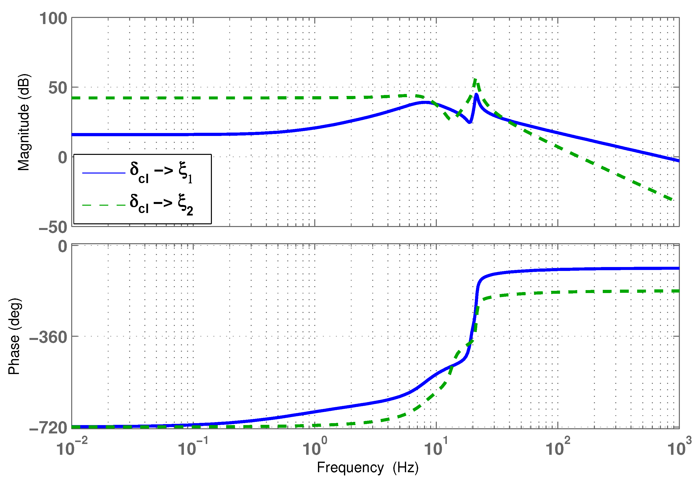
According to the linearized compression system in Equations (3a) and (3b), the system input is the impeller tip clearance and the two outputs are the compressor mass flow rate and the plenum pressure rise . For the throttle valve opening value greater than 0.185, the compression system remains stable in the neighborhood of the equilibrium operating point. In order to capture the instability dynamics during a surge condition, the equilibrium value of the throttle valve opening was chosen to be 0.17 for linearization. For the compression system model linearized at , the frequency responses from the impeller tip clearance to two outputs, and , are shown in Figure 9. From the Bode plots, it can be noticed that there are two resonances that occur at around 7 Hz and 21 Hz, which correspond to the frequencies of the surge limit cycle and the acoustic resonance of piping.
For the surge controller implementation, the information of the mass flow rate and the plenum pressure rise are required. However, the orifice flow meter installed in the system, described earlier in this section, provides only the steady-state flow. For the feedback control operation, transient flow rate measurement is required. Therefore, a mass flow rate observer needs to be designed to provide the transient flow rate information. In [9], the observer was derived based on the system state equations given in Equations (1a)–(1d). The mass flow rate observer state equations are given as follows:
where is the estimated mass flow rate and is the observed nondimensional steady-state compressor pressure rise, which can be obtained from the characteristic curve illustrated in Figure 8, and c = 5.
3. Fractional-Order Control of Compressor Surge
In this section, we present our design and implementation of a fractional-order PD surge controller for the centrifugal compressor test rig described in Section 2. A detailed description of fractional-order PID control and its implementation can be found in [10].
3.1. Design of Fractional-Order Proportional-Derivative Control (FOPD) Surge Controller
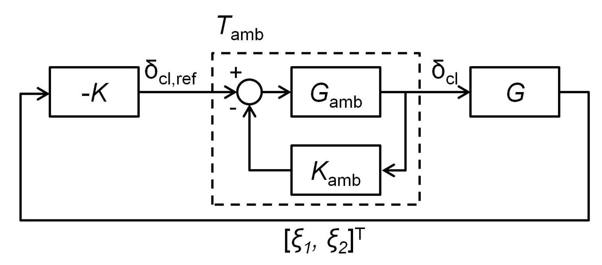
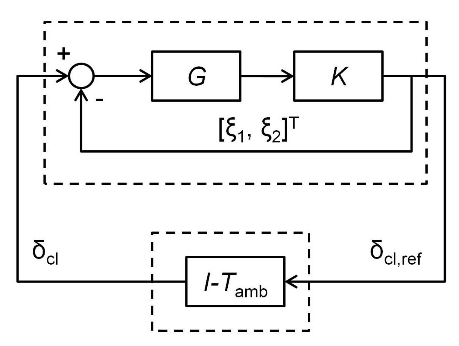
The objective in the surge control design is to stabilize the compression system in the surge condition, where the equilibrium operating point (, ) is beyond the surge line limit. As shown in Figure 10, the two inputs of the surge controller K from the compression system G are the compressor mass flow rate and the plenum pressure rise . The controller output is the reference impeller tip clearance , which is fed into the closed-loop thrust AMB system [10]. The thrust AMB controller will track the desired tip clearance specified by the surge controller in order to induce an appropriate amount of pressure rise for surge stabilization. In the actual implementation, it is impossible to have perfect tracking by the thrust AMB due to external disturbances. This means that the performance of the surge controller will be degraded. Due to this limitation, the surge control design must take into account disturbances, which can impact the interaction between the surge and thrust AMB controllers. Moreover, Yoon et al. suggested in [9] that the closed-loop system shown in Figure 10 can be restructured as shown in Figure 11. This way, the closed-loop dynamics of the compression system and the rotor/thrust AMB system are separated.
In this work, the surge controller for each input–output pair consists of a fractional-order proportional-derivative (FOPD) controller. The structure of the controller is shown in Equation (5),
where is the order of the derivative, while and are the controller gains. Additionally, there is a second-order low-pass filter and a notch filter to suppress the unwanted signal at the specified frequencies. The center frequency of the notch filter is placed at a frequency slightly lower than the critical frequency of the system (approximately 5–10 Hz lower) so that the designed controller can provide more damping at the critical frequency. The structure of the notch filter is
where is the center frequency of the notch and indicates the notch sharpness.
To obtain the best possible parameters of the FOPD controller, a proper tuning method is necessary. There are quite a few tuning methods for fractional-order controllers due to the increasing interest in adopting a fractional-order controller to achieve better performance. Fractional-order controller tuning methods have been studied for both linear and nonlinear systems. Recent fractional-order controller tuning methods for linear systems include the fractional-order model predictive frequency control of an islanded microgrid [12], the fractional-order controller tuning based on frequency data [13], and the parameter tuning for the fractional-order phase-lead compensator [14]. There are also several tuning methods for nonlinear systems such as fractional-order controller tuning for the data-driven MIMO model-free reference tracking control with nonlinear state-feedback [15] and the design of fractional-order sliding mode control for a class of second-order perturbed nonlinear systems [16]. However, this study focuses on parameter tuning for a fractional-order PID controller, where the objective of the tuning emphasizes only on the controller gains and orders. There are three main approaches to fractional-order PID controller tuning—the analytical, rule-based, and numerical approaches. The analytical tuning methods for a fractional-order PID controller have been studied, such as the fractional-order PI controller applied to the traction system of an electric vehicle [17] and the tuning of fractional-order PID controllers based on integral performance criteria using Fourier series method [18]. Several other analytical tuning methods can be found in [19,20,21]. The rule-based tuning methods need to include an additional testing process such as relay feedback test before applying the auto-tuning [22,23]. The analytical and rule-based methods require that a plant is open-loop stable. Due to this limitation, this study emphasizes only on the numerical tuning methods since the compression system that is linearized to capture the surge phenomenon is open-loop unstable.
The numerical tuning methods for fractional-order PID controllers are mainly optimizing the specified objectives by adjusting controller gains and orders. Popular optimization algorithms used in numerical tuning methods are evolutionary algorithms including Genetic Algorithm (GA), Particle Swarm Optimization (PSO), and Differential Evolution (DE) due to their capability to improve global minimum search. A detailed procedure for parameter tuning of these optimization algorithms can be found in [10].
The objectives for the surge controller tuning are adopted from [9] as follows, where we refer to the corresponding transfer functions as objective transfer functions.
- Stability of closed-loop system: The closed-loop stability condition is derived from the Small Gain Theorem. The optimization goal is to have 1.
- Robust stability condition:
- Control effort according to the reference equilibrium operating point condition:
- Transmission of the input disturbance to the plant output signal condition:
- Closed-loop dynamics from the reference equilibrium operating point to the plant output signal condition:
where
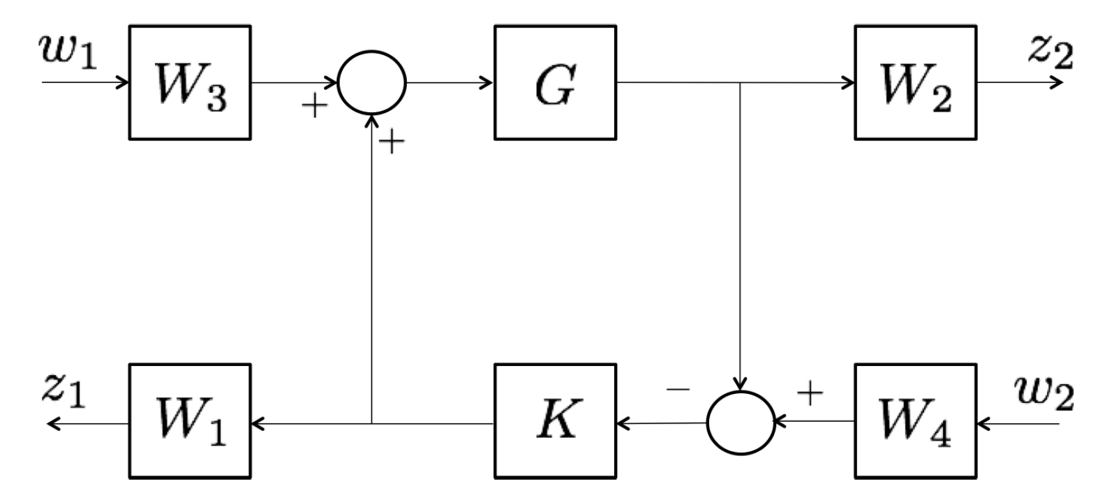
G is the transfer function of the compression system (3a) and (3b), and the weighting functions—as shown in Figure 12—are
Similar to the fractional-order rotor suspension control design in [10], all five objective functions are combined into a single cost function,
for which the optimization is carried out. The optimization goal is to have the value of this combined objective function to be smaller than 1. As in [10], the investigation of three tuning methods for the controller parameters is performed. These tuning methods are Genetic Algorithm (GA), Differential Evolution (DE), and Particle Swarm Optimization (PSO). The population size is chosen as 200, which is the same value used in [10] because the number of parameters to tune is the same. The crossover rate, the weight factor, the acceleration rate, and the mutation rate are also kept the same as in [10]. During the optimization process, the FOPD controller included in the objective transfer functions is realized as an integer-order transfer function by using the Oustaloup’s approximation method as explained in [10]. In this work, a fractional-order integrator is approximated by a second-order integer order transfer function.
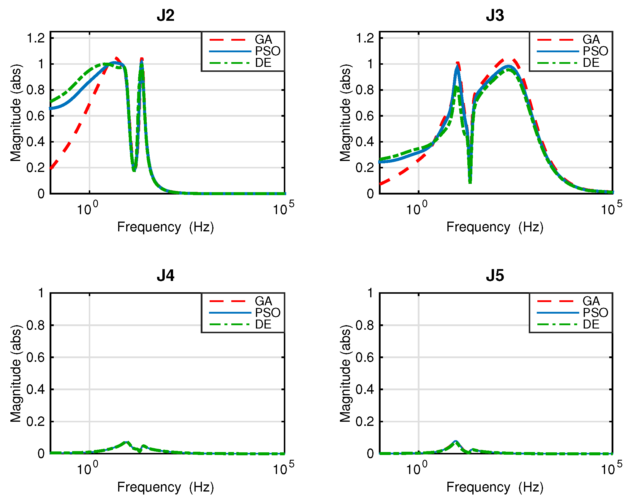
Table 6 summarizes the resulting infinity norms of the objective function resulting from different tuning methods. In addition, the resulting magnitude plots of all objective transfer functions, except the stability objective, resulting from the three different tuning methods are shown in Figure 13. It can be observed that only the DE algorithm results in the maximum magnitudes of the objective functions smaller than 1. Therefore, this controller design will be used for implementation and comparison with the other kind of controllers.
Table 7 summarizes the values of the FOPD controller and the notch filter parameters obtained from the DE optimization. For comparison, the conventional PD controller,
is tuned based on the same objectives and algorithms as the FOPD controller (Table 8). Moreover, the surge controller designed in [9] for the same compression system is also considered.
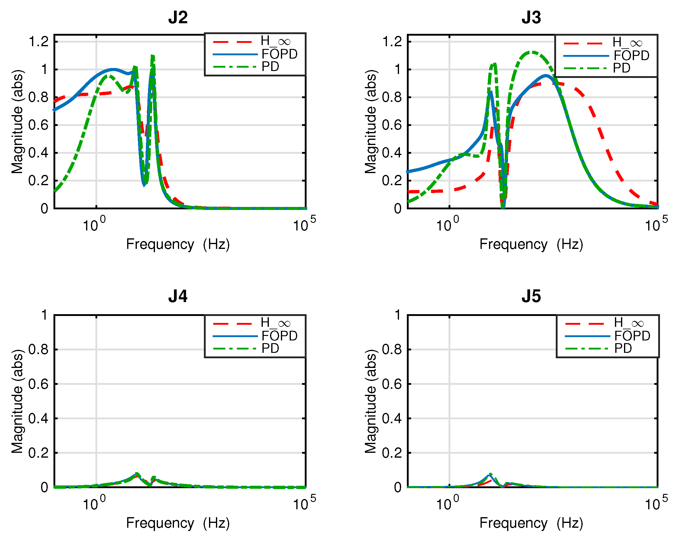
Table 9 summarizes the values of all objectives for the PD controller (20), the FOPD controller (5), and the controller [9]. The corresponding magnitude plots of the objective transfer functions are illustrated in Figure 14. Note that the practical realization of the fractional-order component of the designed FOPD controller is done by applying the Oustaloup’s approximation mentioned earlier. Model reduction is carried out by the Control Toolbox in Matlab on all the compared controllers in this study for ease of implementation.
3.2. Simulation Results of Surge Control
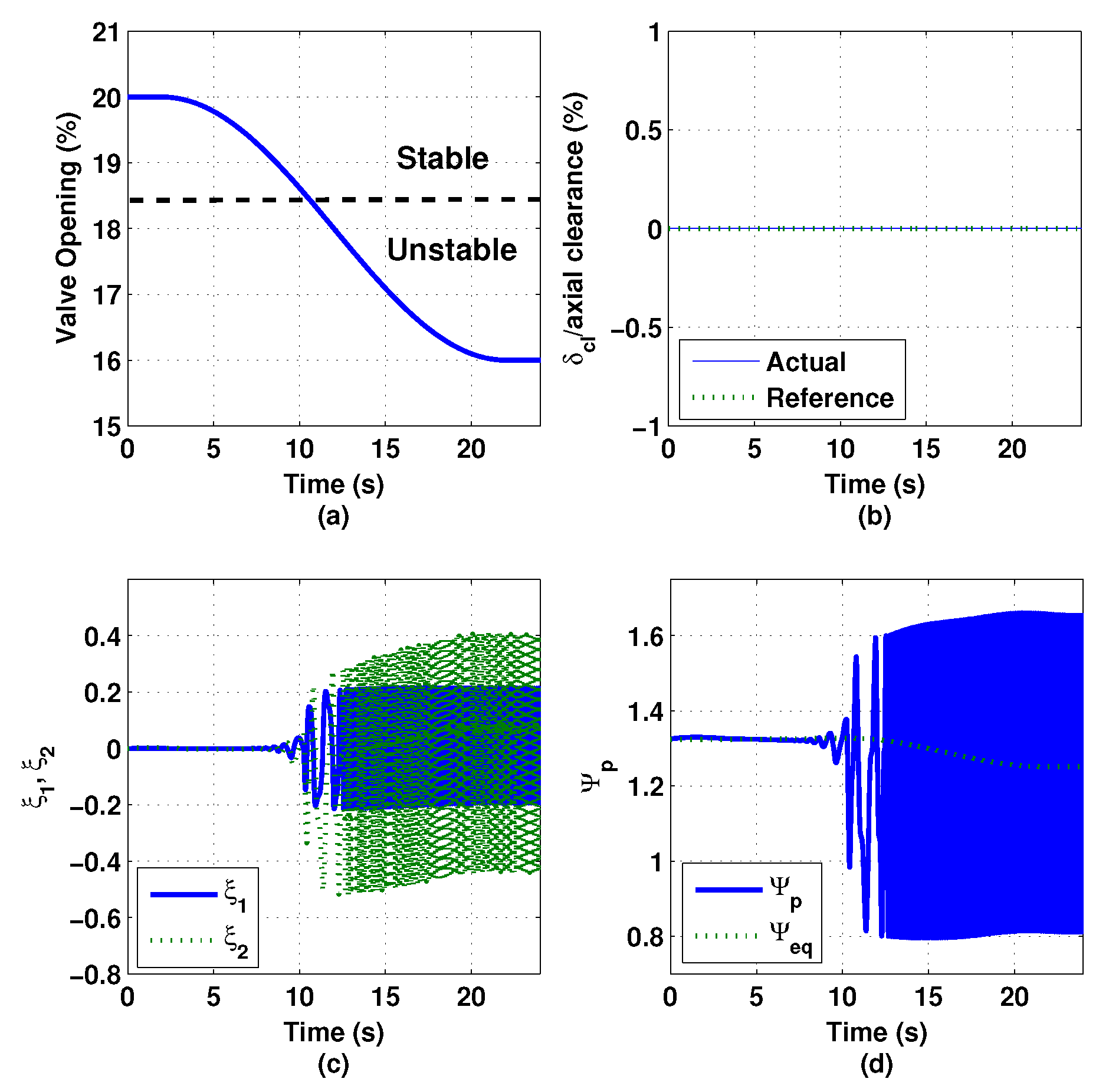
With the derived surge controller, simulation was carried out on the nonlinear compression system model described by Equations (1a)–(1d). The closed-loop dynamics of the thrust AMB, , is represented by a third-order low-pass Butterworth filter with the cutoff frequency of 70 Hz. Figure 15 shows the simulation results of the compression system when the surge controller is inactivated. In the simulation, the throttle valve was gradually closed down from 20% opening (stable) to 16% opening (unstable), where the crossing between the two regions occurs at 18.5% opening. Since there is no surge controller activated, the variation of the impeller tip clearance remains zero, as shown in Figure 15b. Figure 15c shows that the states and of the compression system demonstrate large oscillation magnitudes after the system enters the surge region. Similarly, the value of the plenum pressure rise demonstrates large oscillation magnitudes after the system enters the surge region, as shown in Figure 15d.
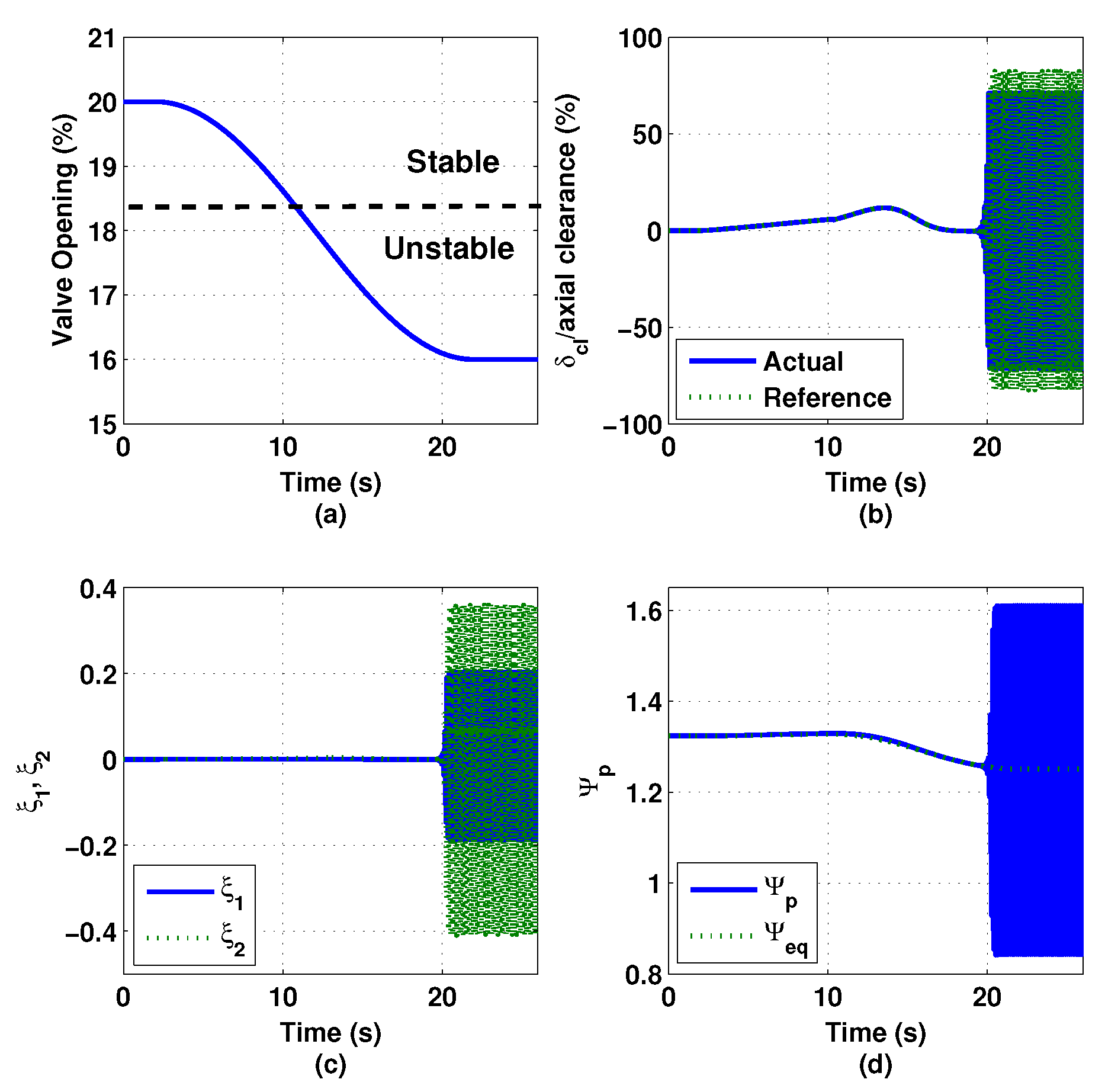
Figure 16 shows the simulation results of the compression system when using the integer-order PD (IOPD) controller that is tuned with the same algorithm and objectives as for the FOPD controller. This IOPD controller can stabilize the compression system even after the system enters the surge region, but the system becomes unstable at approximately 16.2% of throttle valve opening.
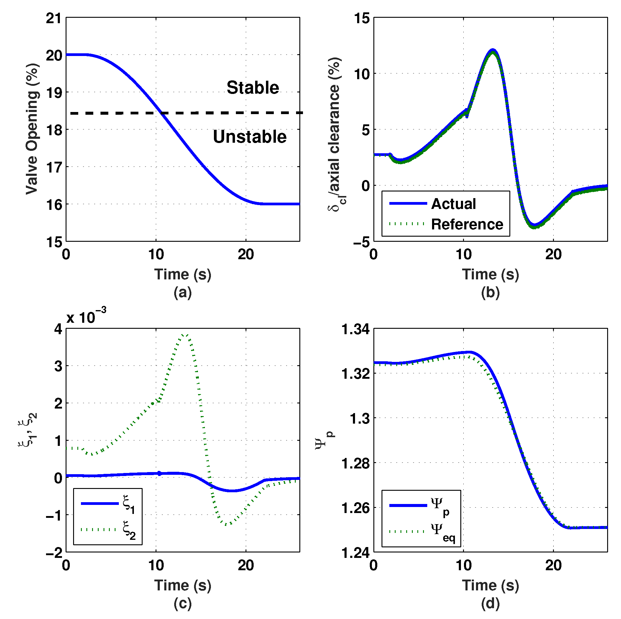
Figure 17 shows the simulation results of the compression system when the surge controller is activated. The compression system is stabilized even when it enters the unstable region by modulating the impeller tip clearance, as shown in Figure 17b. Both states and of the compression system are still stable even after the system enters the unstable region, as shown in Figure 17c. Finally, Figure 17d shows the values of the plenum pressure rise and the equilibrium pressure rise that stabilize the compression system.
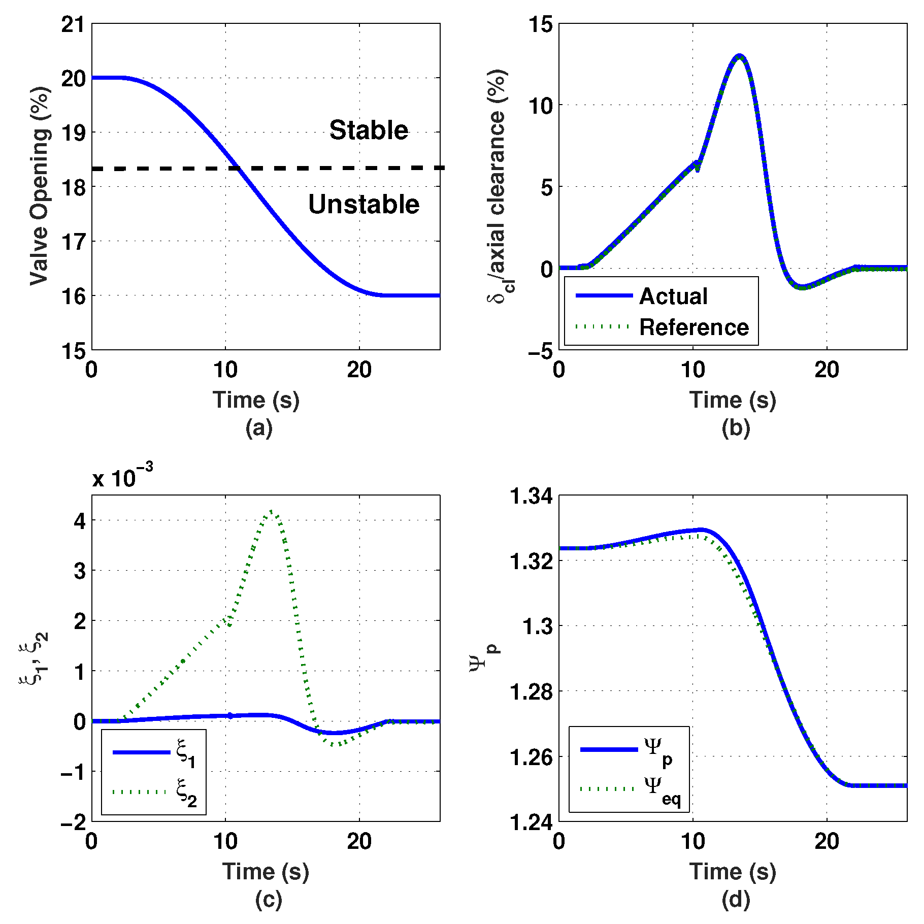
Similar to the performance provided by the surge controller, the FOPD surge controller stabilizes the compression system. In addition, the peak value of the tip clearance modulation is approximately the same as in the case of the surge controller, as shown in Figure 18b. In addition, the maximum values of the states shown in Figure 18c stay stable after the system enters the surge region. It can be seen that the FOPD surge controller performs better than the IOPD surge controller. Finally, the simulation results demonstrate that the FOPD surge controller performs at a similar level as the surge controller.
3.3. Experimental Test of Surge Control
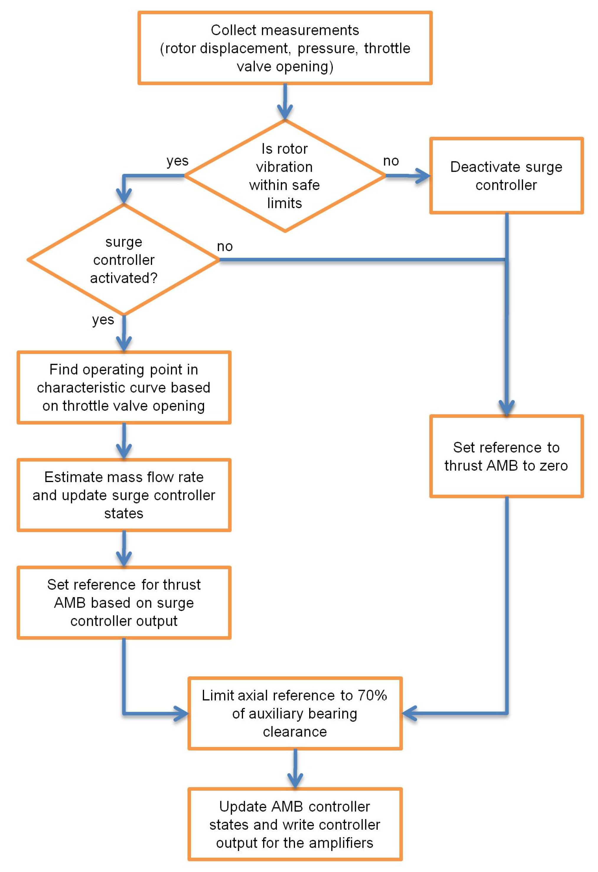
The surge controller will be activated when needed on top of the rotor suspension controllers that are always active throughout the operating period. Since the surge control implementation will be tested at 16,290 rpm, at which the system stores high energy, an accidental contact by improper surge controller implementation can cause more damage to the compressor than the surge instability. Therefore, a safety mechanism for the surge controller activation is required. In our experiments, prior to the surge controller activation, rotor vibration is checked. If rotor vibration is within the predefined limit, the surge controller is engaged in the control process. Then, the reference of the rotor axial position computed by the surge controller is limited to ±70% of the available axial clearance. Otherwise, the reference of the rotor axial position is set to zero for a safe operating environment. The flow chart of the surge controller operation is illustrated in Figure 19.
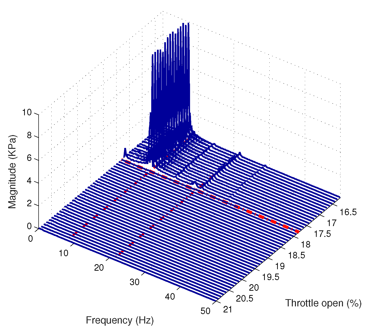
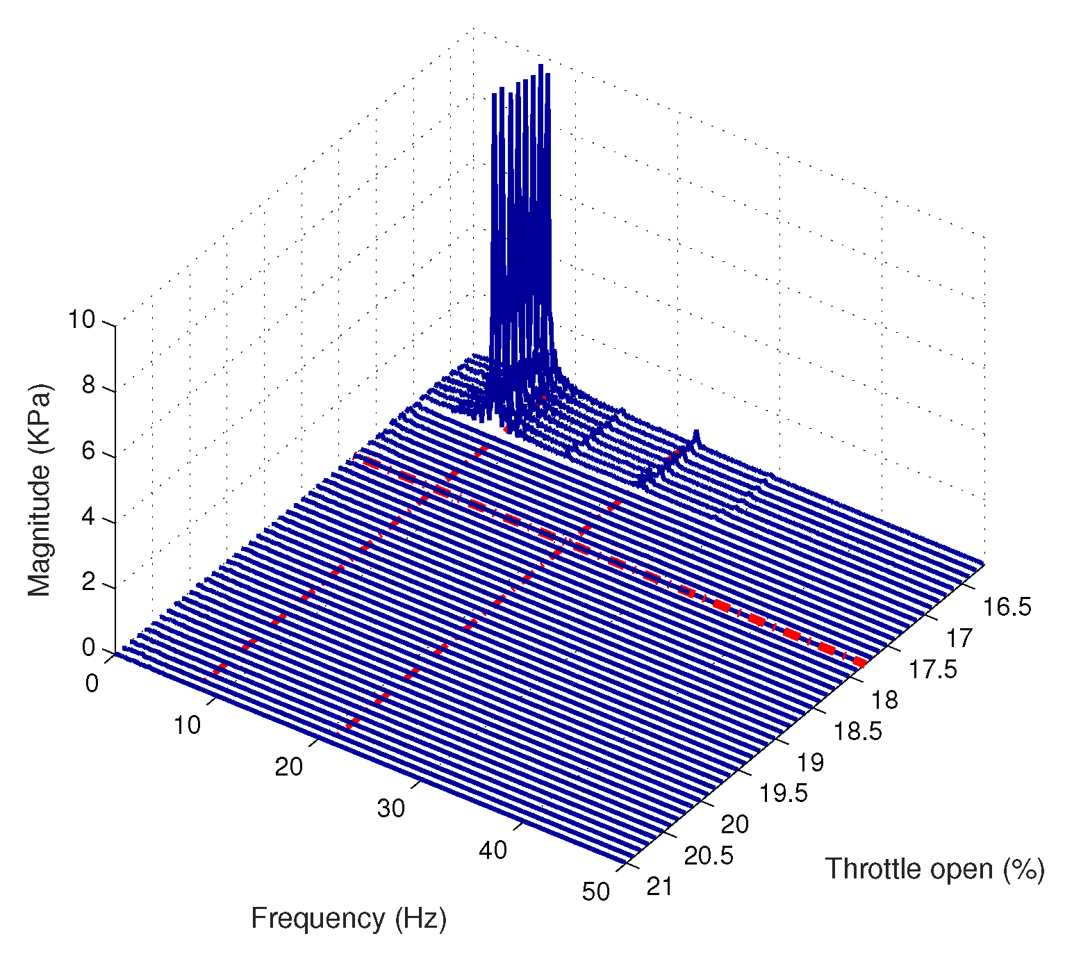
With the rotor spinning at 16,290 rpm, the system is driven into surge by gradually closing down the throttle valve starting from a 21.0% opening, in 0.1% decrements, for smooth operation. Figure 20 shows that the compression system enters the surge region at a 17.8% of the throttle valve opening in the absence of the surge controller. The frequency response plot shows large peaks at approximately 7 Hz and 21 Hz, which agrees with the prediction of the compression system characteristics described in Section 2.2.
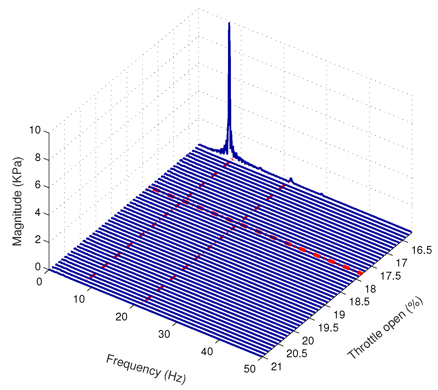
For the next surge test, the IOPD surge controller is activated under the same testing condition as in the previous test. Figure 21 shows the frequency response of the measured plenum pressure rise when the IOPD surge controller is activated. The large peaks of the frequency response initiate at a 16.9% throttle valve opening position. The result shows that, with the IOPD surge controller activated, the compression system can operate stably beyond the original surge limit.
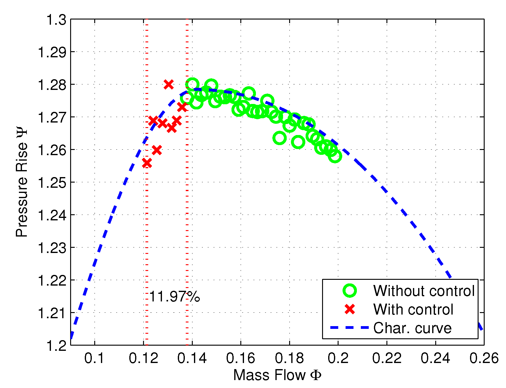
Figure 22 shows the nondimensional mass flow rate and the plenum pressure rise on the characteristic curve during stable operation. The measurements with the surge controller inactivated are marked by ‘o’. These values are measured from 21% valve opening until 17.8%, where the surge initiates. The measurements marked by ‘x’ represent the extended operating points when the IOPD controller is activated. It can be observed that the surge limit is extended in terms of the mass flow range from the uncontrolled case by 11.97%.
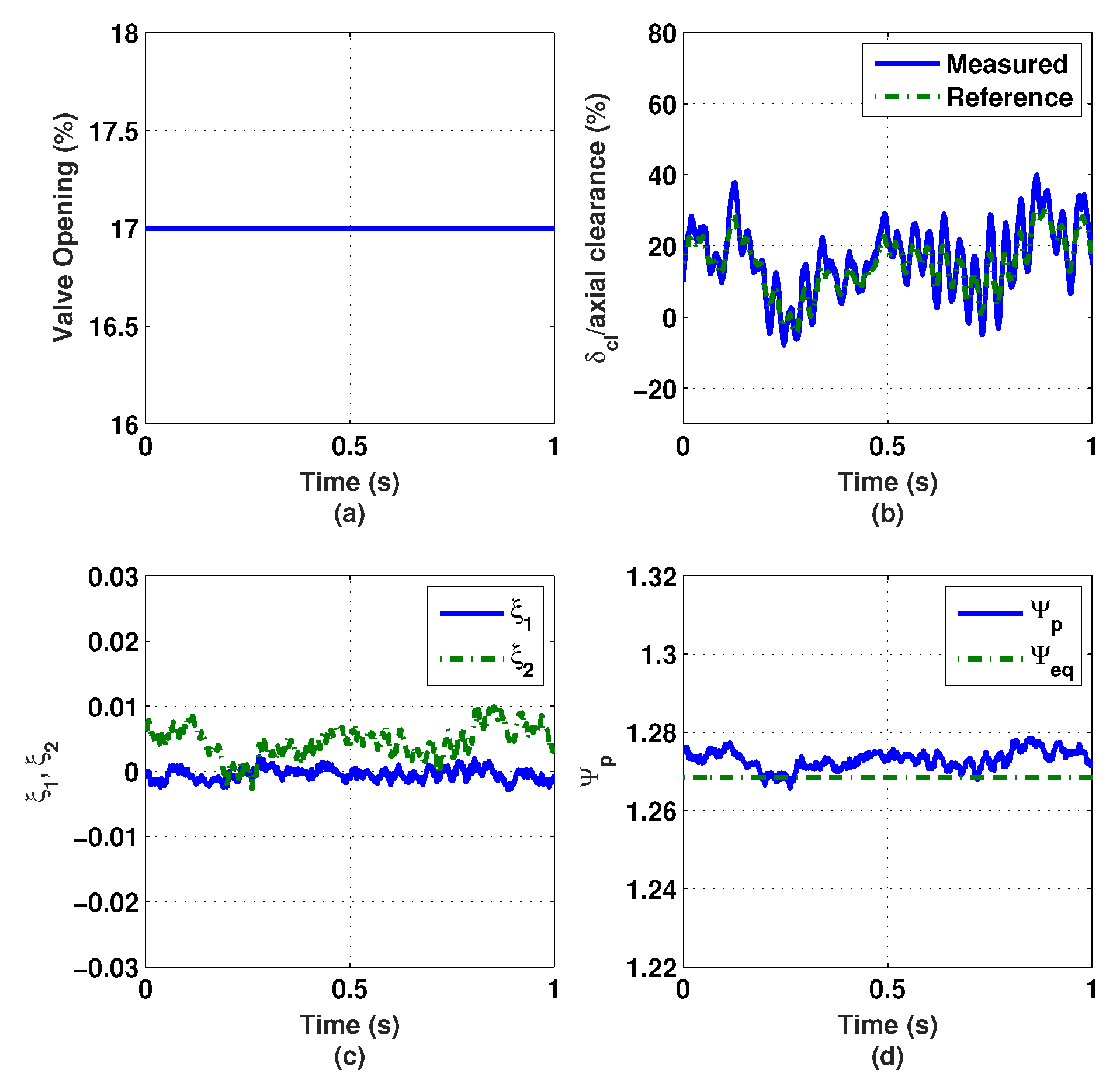
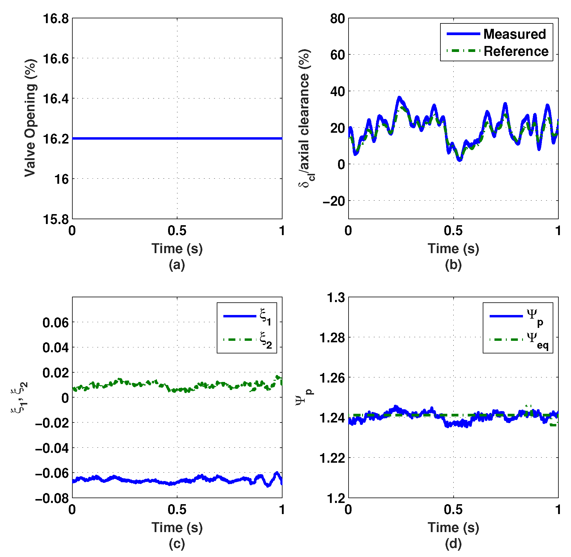
In addition, the measured and reference ratio of the impeller tip clearance and the available axial clearance are shown in Figure 23b. The maximum value of the impeller tip clearance is about 40% of the available axial clearance. This shows that the IOPD surge controller can operate stably with some axial position margin compared with the predefined ±70% of the available clearance. Figure 23c shows the values of the surge controller states, and , when the throttle valve is opened at 17.0%. The nondimensional measured pressure rise and its equilibrium values are illustrated in Figure 23d.
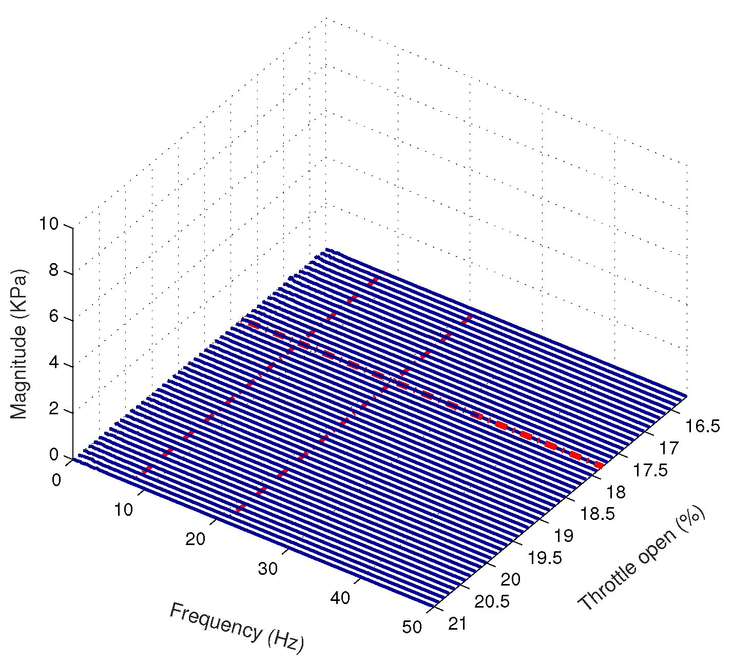
For the case of the FOPD surge controller test, Figure 24 shows the frequency response of the measured plenum pressure rise. It can be noticed that the compression system enters surge when the throttle valve opens at 16.2%, which further extends the surge limit. Recall that the IOPD surge controller remains stable until 17.0% opening.
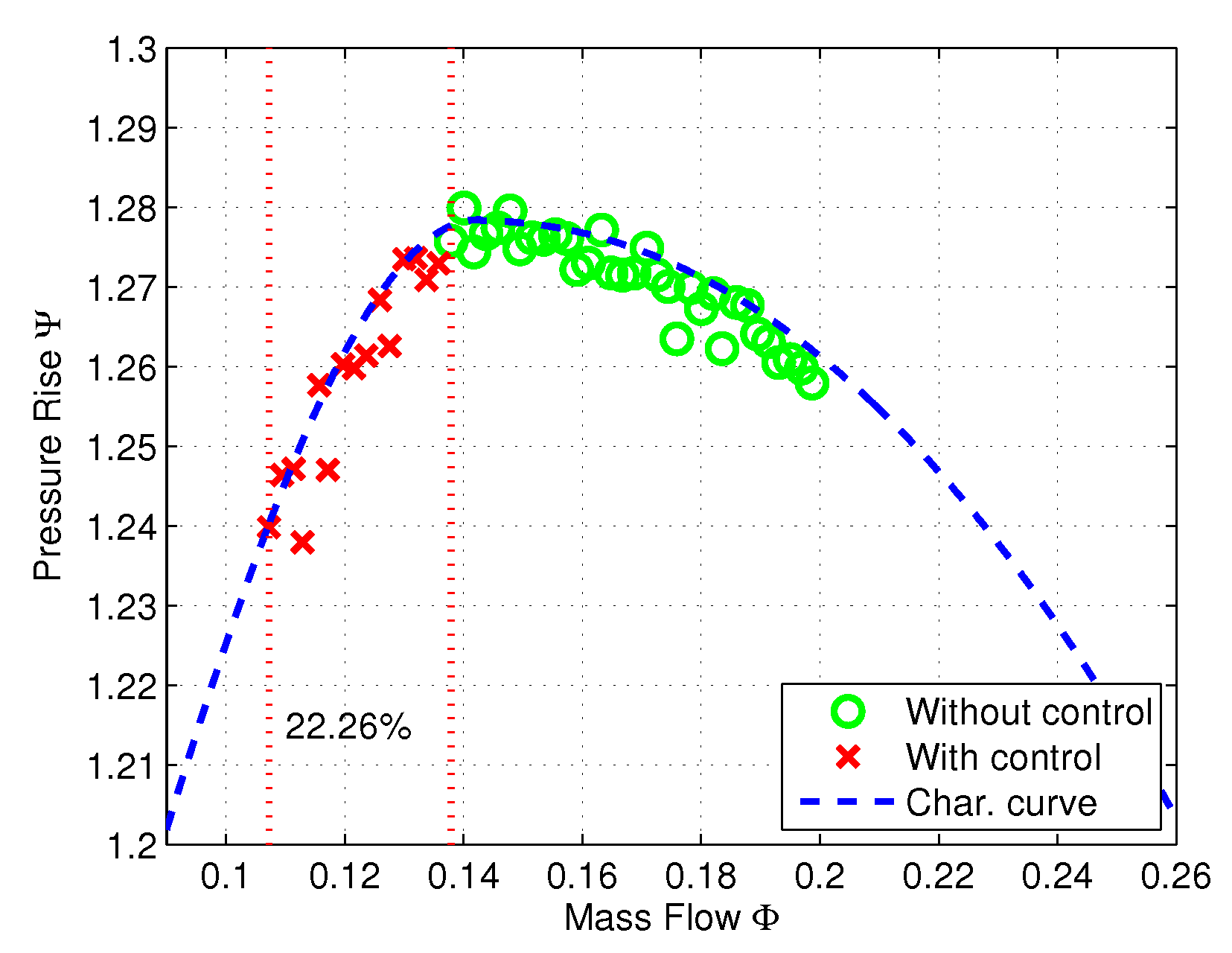
Figure 25 shows the nondimensional mass flow rate and the plenum pressure rise on the characteristic curve during stable operation with the FOPD surge controller activated after the surge limit. The measurements with the FOPD surge controller inactivated are marked by ‘o’. These values are measured from 21% valve opening until 17.8%, where the surge initiates. The measurements marked by ‘x’ represent the extended operating points when the FOPD controller is activated. It can be observed that the surge limit is extended in terms of the mass flow range from the uncontrolled case by 22.26%.
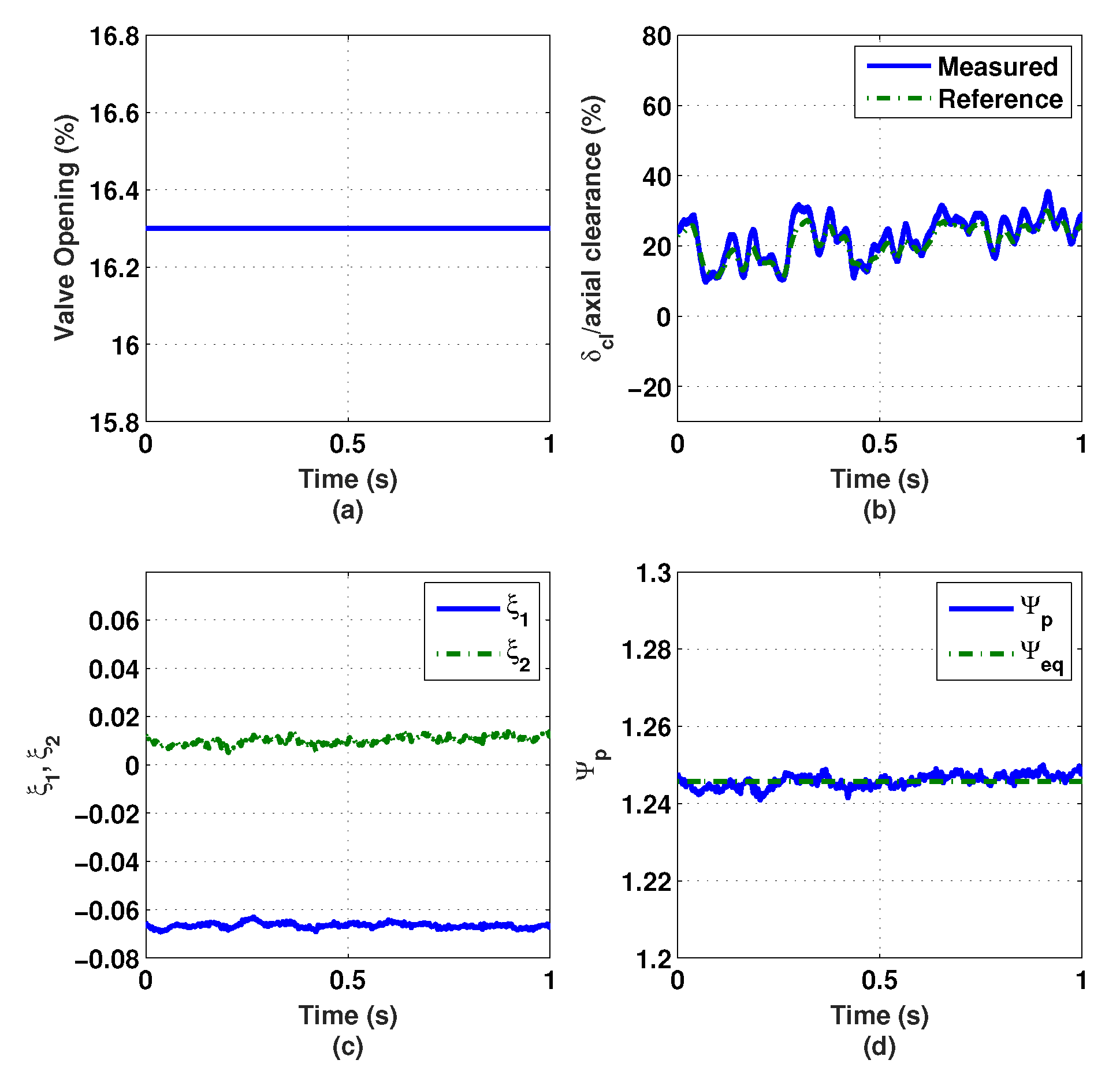
In addition, the maximum value of the impeller tip clearance is approximately 35% of the available axial clearance, as shown in Figure 26b. This shows that the FOPD surge controller results in a slightly larger axial clearance margin than the IOPD surge controller case. Figure 26c shows the values of the surge controller states, and , when the throttle valve is opened at 16.3%. The nondimensional measured pressure rise and its equilibrium values are illustrated in Figure 26d.
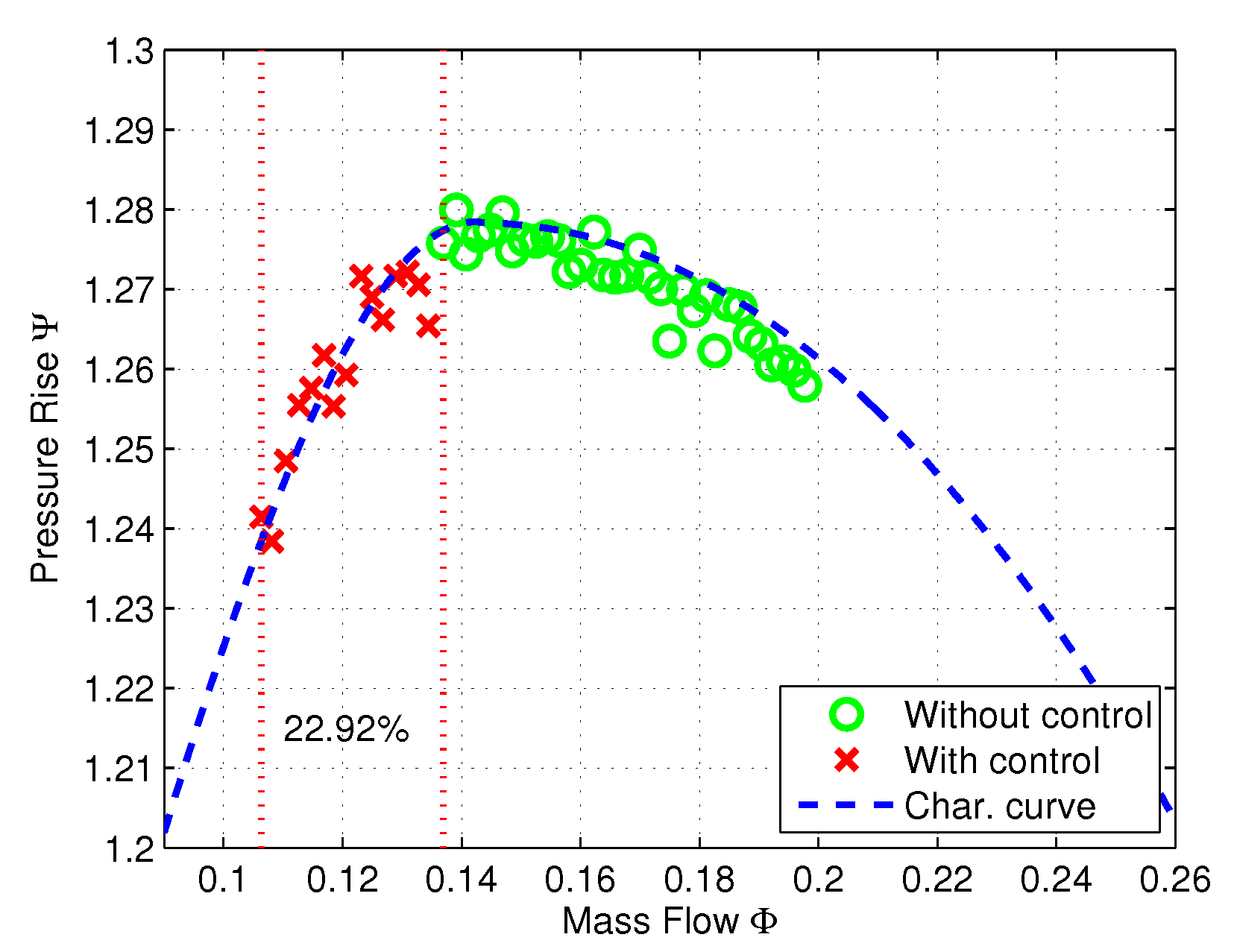
Finally, for the case when the surge controller is activated, Figure 27 shows that the compression system remains stable when the throttle valve opens as small as 16.2%. This extends the throttle valve opening for another 0.1% beyond the FOPD surge controller case. Figure 28 shows the nondimensional mass flow rate and the plenum pressure rise on the characteristic curve during stable operation with the surge controller activated after the surge limit. The measurements with the surge controller inactivated are marked by ‘o’. These values are measured from 21% valve opening until 17.8%, where the surge initiates. The measurements marked by ‘x’ represent the extended operating points when the controller is activated. It can be observed that the surge limit is extended in terms of the mass flow range from the uncontrolled case by 22.92%.
In addition, the maximum value of the impeller tip clearance is about 35% of the available axial clearance, as shown in Figure 29b. This shows that the surge controller can operate stably with approximately the same axial clearance margin as the FOPD surge controller case. Figure 29c shows the values of the surge controller states, and , when the throttle valve is opened at 16.2%. The nondimensional measured pressure rise and its equilibrium values are illustrated in Figure 29d.
4. Discussions
This paper demonstrates the design, analysis, and implementation of a fractional-order PD controller (FOPD) for the control of surge in a centrifugal compressor by active magnetic bearings (AMBs). This is the first time that the FOPD controller is designed for a surge control and implemented on a compressor equipped with magnetic bearings. The FOPD controller is designed based on the control objectives given by prespecified weighting functions. Three tuning methods—Genetic Algorithm (GA), Differential Evolution (DE), and Particle Swarm Optimization (PSO)—for the controller parameters are investigated for their effectiveness. The result shows that the DE optimization algorithm achieves the best performance among the three. Additionally, the IOPD controller is designed based on the same objectives and tuning algorithm. Simulation results show that the IOPD controller can stabilize the compression system beyond the surge limit, but not as much as in the case of the FOPD and the surge controllers. The simulation results are validated by the experimental testing on the compressor test rig. The experimental results show that the IOPD surge controller can extend the surge limit in terms of the mass flow range from the uncontrolled case by 11.96%. For the case of the FOPD and the surge controllers, the surge limit is extended by 22.26% and 22.92%, respectively. From these simulation and experimental results, it is concluded that a properly tuned FOPD controller—which has a simpler controller structure and is easy to design—can achieve performance that is similar to or even better than an advanced controller such as .
Author Contributions
The two authors contributed equally to this work. All authors have read and agreed to the published version of the manuscript.
Funding
This research received no external funding.
Conflicts of Interest
The authors declare no conflict of interest.
References
- Kirk, R. Evaluation of amb turbomachinery auxiliary bearings. J. Vib. Acoust. 1999, 121, 156–161. [Google Scholar] [CrossRef]
- Daikin Applied. Application Guide Centrifugal Choiller Fundamentals. Available online: https://www.daikinapplied.com/o365/GetDocument/Doc100/Daikin_AG_31-002_Centrifugal_Chiller_Fundamentals_Guide_Vers_2.2.pdf (accessed on 1 March 2020).
- Centrifugal Compressor. Available online: http://howitsworkss.blogspot.com/2015/06/centrifugal-compressor.html (accessed on 1 March 2020).
- McMillan, G. Centrifugal and Axial Compressor Control; Momentum Press: New York, NY, USA, 2010. [Google Scholar]
- Arnulfi, G.L.; Giannattasio, P.; Micheli, D.; Pinamonti, P. An innovative device for passive control of surge in industrial compression systems. J. Turbomach. 2001, 123, 473–482. [Google Scholar] [CrossRef]
- Blanchini, F.; Giannattasio, P.; Micheli, D.; Pinamonti, P. Experimental evaluation of a high-gain control for compressor surge suppression. J. Turbomach. 2002, 124, 27–35. [Google Scholar] [CrossRef]
- Senoo, Y.; Ishida, M. Deterioration of compressor performance due to tip clearance of centrifugal impellers. J. Turbomach. 1987, 109, 55–61. [Google Scholar] [CrossRef]
- Sanadgol, D. Active Control of Surge in Centrifugal Compressors Using Magnetic Thrust Bearing Actuation. Ph.D. Thesis, University of Virginia, Charlottesville, VA, USA, May 2006. [Google Scholar]
- Yoon, S.Y.; Lin, Z.; Allaire, P. Control of Surge in Centrifugal Compressors by Active Magnetic Bearings; Springer: London, UK, 2012. [Google Scholar]
- Anantachaisilp, P.; Lin, Z. Fractional order PID control of rotor suspension by active magnetic bearings. Actuators 2017, 6, 4. [Google Scholar] [CrossRef] [Green Version]
- Greitzer, E.M. Surge and rotating stall in axial flow compressors part i: Theoretical compression system model. J. Eng. Gas Turbine Power 1976, 98, 190–198. [Google Scholar] [CrossRef]
- Chen, M.R.; Zeng, G.Q.; Dai, Y.X.; Lu, K.D.; Bi, D.Q. Fractional-order model predictive frequency control of an islanded microgrid. Energies 2019, 12, 84. [Google Scholar] [CrossRef] [Green Version]
- Sayyaf, N.; Tavazoei, M.S. Desirably adjusting gain margin, phase margin, and corresponding crossover frequencies based on frequency data. IEEE Trans. Ind. Inform. 2017, 13, 2311–2321. [Google Scholar] [CrossRef]
- Safaei, M.; Tavakoli, S. Tuning of robust fractional-order phase-lead compensators using pole placement and pole-zero ratio minimization. J. Vib. Control 2018, 24, 5379–5390. [Google Scholar] [CrossRef]
- Radac, M.B.; Precup, R.E. Data-driven MIMO model-free reference tracking control with nonlinear state-feedback and fractional order controllers. Appl. Soft Comput. 2018, 73, 992–1003. [Google Scholar] [CrossRef]
- Govea-Vargas, A.; Castro-Linares, R.; Duarte-Mermoud, M.A.; Aguila-Camacho, N.; Ceballos-Benavides, G.E. Fractional order sliding mode control of a class of second order perturbed nonlinear systems: Application to the trajectory tracking of a quadrotor. Algorithms 2018, 11, 168. [Google Scholar] [CrossRef] [Green Version]
- Munoz-Hernandez, G.A.; Mino-Aguilar, G.; Guerrero-Castellanos, J.F.; Peralta-Sanchez, E. Fractional rrder PI-based control applied to the traction system of an electric vehicle (EV). Appl. Sci. 2020, 10, 364. [Google Scholar] [CrossRef] [Green Version]
- Deniz, F.N.; Yüce, A.; Tan, N.; Atherton, D.P. Tuning of fractional order PID controllers based on integral performance criteria using Fourier series method. IFAC-PapersOnLine 2017, 50, 8561–8566. [Google Scholar] [CrossRef]
- Caponetto, R.; Fortuna, L.; Porto, D. A new tuning strategy for a non integer order PID controller. In Proceedings of the First IFAC Workshop on Fractional Differentiation and Its Application, Bordeaux, France, 19–21 July 2004; pp. 168–173. [Google Scholar]
- Zhao, C.; Xue, D.; Chen, Y.Q. A fractional order PID tuning algorithm for a class of fractional order plants. In Proceedings of the 2005 IEEE International Conference Mechatronics and Automation, Niagara Falls, ON, Canada, 29 July–1 August 2005; pp. 216–221. [Google Scholar]
- Maione, G.; Lino, P. New tuning rules for fractional PID controllers. Nonlinear Dyn. 2007, 49, 251–257. [Google Scholar] [CrossRef]
- Vinagre, B.M.; Monje, C.A.; Calderon, A.J.; Suarez, J.I. Fractional PID controllers for industry application. A brief introduction. J. Vib. Control 2007, 13, 1419–1429. [Google Scholar] [CrossRef]
- Monje, C.A.; Vinagre, B.M.; Feliu, V.; Chen, Y. Tuning and auto-tuning of fractional order controllers for industry applications. Control Eng. Pract. 2008, 16, 798–812. [Google Scholar] [CrossRef] [Green Version]
Figure 1.
A compressor equipped with magnetic bearings [2].
Figure 1.
A compressor equipped with magnetic bearings [2].

Figure 2.
Compressor characteristic curve [3].
Figure 2.
Compressor characteristic curve [3].

Figure 3.
The compressor and piping system.

Figure 4.
Components of the centrifugal compressor.

Figure 5.
Test rig layout.

Figure 6.
Layout of the control/data-acquisition system of the test rig [9].
Figure 6.
Layout of the control/data-acquisition system of the test rig [9].

Figure 7.
Compression system described by Greitzer’s compression system model.

Figure 8.
Fitted characteristic curve at 16,290 rpm [9].
Figure 8.
Fitted characteristic curve at 16,290 rpm [9].

Figure 9.
Bode plots of the linearized compression system.

Figure 10.
Closed-loop compression system with surge controller diagram.

Figure 11.
Modified closed-loop compression system with surge controller diagram.

Figure 12.
Interconnected system for the design of the surge controller.

Figure 13.
Magnitudes of objective transfer functions resulting from three different tuning methods (GA, DE, and PSO).
Figure 13.
Magnitudes of objective transfer functions resulting from three different tuning methods (GA, DE, and PSO).

Figure 14.
Magnitudes of objective transfer functions for all controllers.

Figure 15.
Simulation results of the compression system with the surge controller inactivated. (a) Value Opening (b) axial clearance (c) and (d) .
Figure 15.
Simulation results of the compression system with the surge controller inactivated. (a) Value Opening (b) axial clearance (c) and (d) .

Figure 16.
Simulation results of the compression system under the integer-order PD (IOPD) surge controller. (a) Value Opening (b) axial clearance (c) and (d) .
Figure 16.
Simulation results of the compression system under the integer-order PD (IOPD) surge controller. (a) Value Opening (b) axial clearance (c) and (d) .

Figure 17.
Simulation results of the compression system under the surge controller. (a) Value Opening (b) axial clearance (c) and (d) .
Figure 17.
Simulation results of the compression system under the surge controller. (a) Value Opening (b) axial clearance (c) and (d) .

Figure 18.
Simulation results of the compression system under the FOPD surge controller. (a) Value Opening (b) axial clearance (c) and (d) .
Figure 18.
Simulation results of the compression system under the FOPD surge controller. (a) Value Opening (b) axial clearance (c) and (d) .

Figure 19.
Flow chart of the surge control implementation [9].
Figure 19.
Flow chart of the surge control implementation [9].

Figure 20.
Waterfall plot of the frequency response of the measured plenum pressure signal at 16,290 rpm with the surge controller inactivated.
Figure 20.
Waterfall plot of the frequency response of the measured plenum pressure signal at 16,290 rpm with the surge controller inactivated.

Figure 21.
Waterfall plot of the frequency response of the measured plenum pressure signal at 16,290 rpm with the IOPD surge controller activated.
Figure 21.
Waterfall plot of the frequency response of the measured plenum pressure signal at 16,290 rpm with the IOPD surge controller activated.

Figure 22.
Compressor steady-state operation on the characteristic curve at 16,290 rpm with the IOPD surge controller activated and inactivated, respectively.
Figure 22.
Compressor steady-state operation on the characteristic curve at 16,290 rpm with the IOPD surge controller activated and inactivated, respectively.

Figure 23.
Experimental results of the compression system under the IOPD surge controller at 17.0% throttle valve opening. (a) Value Opening (b) axial clearance (c) and (d) .
Figure 23.
Experimental results of the compression system under the IOPD surge controller at 17.0% throttle valve opening. (a) Value Opening (b) axial clearance (c) and (d) .

Figure 24.
Waterfall plot of the frequency response of the measured plenum pressure signal at 16,290 rpm with the FOPD surge controller activated.
Figure 24.
Waterfall plot of the frequency response of the measured plenum pressure signal at 16,290 rpm with the FOPD surge controller activated.

Figure 25.
Compressor steady-state operation on the characteristic curve at 16,290 rpm with the FOPD surge controller activated and inactivated, respectively.
Figure 25.
Compressor steady-state operation on the characteristic curve at 16,290 rpm with the FOPD surge controller activated and inactivated, respectively.

Figure 26.
Experimental results of the compression system under the FOPD surge controller at 16.3% throttle valve opening. (a) Value Opening (b) axial clearance (c) and (d) .
Figure 26.
Experimental results of the compression system under the FOPD surge controller at 16.3% throttle valve opening. (a) Value Opening (b) axial clearance (c) and (d) .

Figure 27.
Waterfall plot of the frequency response of the measured plenum pressure signal at 16,290 rpm with the surge controller activated.
Figure 27.
Waterfall plot of the frequency response of the measured plenum pressure signal at 16,290 rpm with the surge controller activated.

Figure 28.
Compressor steady-state operation on the characteristic curve at 16,290 rpm with the surge controller activated and inactivated, respectively.
Figure 28.
Compressor steady-state operation on the characteristic curve at 16,290 rpm with the surge controller activated and inactivated, respectively.

Figure 29.
Experimental results of the compression system under the surge controller at 16.2% throttle valve opening. (a) Value Opening (b) axial clearance (c) and (d) .
Figure 29.
Experimental results of the compression system under the surge controller at 16.2% throttle valve opening. (a) Value Opening (b) axial clearance (c) and (d) .


Table 1.
Properties of active magnetic bearings (AMBs).
| Radial AMB | (A) | (N/m) | (N/A) |
|---|---|---|---|
| Motor side | 3 | 1.27 × | 199.34 |
| Compressor side | 4 | 2.26 × | 265.86 |
| Thrust AMB | 3 | 4.23 × | 664.12 |
Table 2.
Properties of instrumentation.
| AMB | Motor Side | Compressor Side | Thrust |
|---|---|---|---|
| Amplifier gain (A/V) | 1.5 | 1.5 | 1.5 |
| Amplifier bandwidth (rad/s) | 5026.5 | 5026.5 | 5026.5 |
| Sensor gain (V/m) | 3.937 × | 3.937 × | 3.937 × |
| Sensor bandwidth (rad/s) | 1.26 × | 1.26 × | 1.26 × |
| Maximum slew rate (N/s) | 2.2 × | 2.2 × | 1.9 × |
Table 3.
Compressor parameters.
| Parameter | Unit | Value |
|---|---|---|
| Maximum speed | rpm | 23,000 |
| Design mass flow rate | kg/s | 0.833 |
| Design pressure ratio | - | 1.68 |
| Impeller tip diameter | mm | 250 |
| Impeller tip blade height | mm | 8.21 |
| Inducer hub diameter | mm | 56.3 |
| Inducer diameter | mm | 116.72 |
Table 4.
Ducting system parameters.
| Parameter | Unit | Value |
|---|---|---|
| Piping diameter | m | 0.203 |
| Inlet piping length | m | 5.2 |
| Exhaust piping length | m | 21.3 |
| Plenum volume #1 | 0.07 | |
| Plenum volume #2 | 0.23 | |
| Plenum volume #3 | 0.49 |
Table 5.
Compression system model parameters.
| Parameter | Symbol | Unit | Value |
|---|---|---|---|
| Comp. duct length | m | 1.86 | |
| Comp. duct cross. area | 0.0082 | ||
| Corrected coeff | - | −172.6 | |
| Corrected coeff | - | 36.88 | |
| Corrected coeff | - | 1.029 | |
| Design tip clearance | mm | 0.6 | |
| Greitzer stab. parameter | B | - | 0.44 |
| Helmholtz freq. | rad/s | 80.1 | |
| Impeller tip speed | U | m/s | 213.24 |
| Impeller blade height | mm | 8.21 | |
| Inlet pressure | Pa | 101,325 | |
| Inlet gas density | kg/ | 1.165 | |
| Line dissipation number | d | - | 2.83 × 10 |
| Line impedance constant | Z | Pa s/m | 4.39 × 10 |
| Plenum volume | 0.049 | ||
| Pipeline length | L | m | 6.5 |
| Throttle constant | - | 1.7197 |
Table 6.
Comparison of the performance of different tuning methods. GA—Genetic Algorithm, DE—Differential Evolution, PSO—Particle Swarm Optimization.
Table 6.
Comparison of the performance of different tuning methods. GA—Genetic Algorithm, DE—Differential Evolution, PSO—Particle Swarm Optimization.
| Controller Characteristics | GA | DE | PSO |
|---|---|---|---|
| Values of objectives | 1.048 | 0.991 | 1.019 |
Table 7.
Parameters of tuned fractional surge controller.
| Input-Output | |||||
|---|---|---|---|---|---|
| - | 2.49 | 9.11 | 1.123 | 0.709 | 18.46 Hz |
| - | 1.21 | 1.01 | 0.563 | 3.489 | 12.10 Hz |
Table 8.
Parameters of tuned proportional-derivative (PD) surge controller.
| Input-Output | ||||
|---|---|---|---|---|
| - | 3.43 | 7.10 | 0.785 | 18.92 Hz |
| - | 2.08 | 9.07 | 2.663 | 13.47 Hz |
Table 9.
Performance of surge controllers. FOPD—fractional-order proportional-derivative control.
| Controller Characteristics | PD | FOPD | |
|---|---|---|---|
| Values of objectives | 1.143 | 0.991 | 0.969 |
| Controller order as implemented | 6 | 6 | 7 |
© 2020 by the authors. Licensee MDPI, Basel, Switzerland. This article is an open access article distributed under the terms and conditions of the Creative Commons Attribution (CC BY) license (http://creativecommons.org/licenses/by/4.0/).
Share and Cite
MDPI and ACS Style
Anantachaisilp, P.; Lin, Z. Fractional-Order Surge Control of Active Magnetic Bearings Suspended Compressor. Actuators 2020, 9, 75. https://0-doi-org.brum.beds.ac.uk/10.3390/act9030075
AMA Style
Anantachaisilp P, Lin Z. Fractional-Order Surge Control of Active Magnetic Bearings Suspended Compressor. Actuators. 2020; 9(3):75. https://0-doi-org.brum.beds.ac.uk/10.3390/act9030075
Chicago/Turabian StyleAnantachaisilp, Parinya, and Zongli Lin. 2020. "Fractional-Order Surge Control of Active Magnetic Bearings Suspended Compressor" Actuators 9, no. 3: 75. https://0-doi-org.brum.beds.ac.uk/10.3390/act9030075
Note that from the first issue of 2016, this journal uses article numbers instead of page numbers. See further details here.