A Novel Adjustable Damper Design for a Hybrid Passive Ankle Prosthesis


1
Department of Mechanical Engineering, Tarbiat Modares University, Tehran 141556343, Iran
2
Lauflabor Locomotion Laboratory, Institute of Sport Science, Centre for Cognitive Science, Technische Universitat Darmstadt, 64289 Darmstadt, Germany
*
Author to whom correspondence should be addressed.
Actuators 2020, 9(3), 74; https://0-doi-org.brum.beds.ac.uk/10.3390/act9030074
Submission received: 29 June 2020
/
Revised: 3 August 2020
/
Accepted: 12 August 2020
/
Published: 24 August 2020
(This article belongs to the Section Actuators for Medical Instruments)
Abstract
:Specifications of actuators when interacting with biological systems such as the human body are entirely different from those used in industrial machines or robots. One important instance of such applications is assistive devices and prostheses. Among various approaches in designing prostheses, recently, semi-active systems attracted the interest of researchers. Even more, some commercial systems benefit from designs such as implementing an adjustable damper in the ankle prosthesis to increase range of motion. The main reason for adding damper is to assist amputees’ walking locomotion on slopes (especially downward). In this paper, we introduce a hydraulic damper design for use in the transtibial prosthetic foot. In the fabricated hydraulic prosthetic foot, two one-way flow control valves are exploited to tune the damping ratio in the plantar flexion and dorsiflexion, independently. Using the carbon prosthetic foot in series to a damper and spring could improve mimicking intact foot movement. First, we present the details of the damper and the prosthesis mechanical design. Then, we introduce experiment-based modeling for the damper’s conceptual design in the proposed prosthesis using SIM-Hydraulic and MATLAB. This device is fabricated and tested in a pilot experiment. The compact design with reduced weight and size of the prosthetic foot are additional advantages of the proposed prosthetic foot.
1. Introduction
During the last few decades, the rapid increase in the number of amputations [1] has motivated the researcher to provide solutions to overcome lost mobility. As a result, several assistive and rehabilitation devices have been developed to recover the mobility of people struggling with lower limb disabilities such as amputation. Thus far, the simple and low-cost passive prostheses have been widely presented to the market. ESR (energy storage and return) prosthetic foot is a compelling example of these conventional mechanically passive devices [2].
In the first generation of ESR prosthetic feet, most of them had stiff, fixed, and rigid attachments to the prosthetic shank [3]. These passive devices provide a limited range of motion (RoM) which makes them unable to prepare the foot for stable ground contact on uneven terrains (e.g., rough terrains and obstacles) [4,5,6] and attain the smooth rollover dynamics (smooth rotation of the shank) [7,8]. These features can cause clinical issues for users [9,10].
To cope with these issues, the visco-elastic property of intact foot [11] inspired researchers to design prosthetic feet to provide more safety and stability during walking in various surface conditions. An adaptation of the stiffness and damping of these feet can be used to increase RoM for improving rollover dynamics and adapting to different surface conditions (especially slopes) and undesired disturbances. In addition, the increased RoM of these feet allows for an increased stride length and more dynamic maneuvers. To allow an increased RoM compared to ESR feet, developers thought about solutions, including ESR feet augmented by visco-elastic elements. Hence, the addition of passive hydraulically controlled articulation (damper, e.g., with a hydraulic unit) at the point of attachment was proposed [12].
ESR feet that incorporate ankle devices with hydraulically controlled, passive articulation at the point of attachment, have become clinically available (e.g., Mauch [13], Endolite Echelon [14], Ossur Proprio Foot [15], Kinterra [16], Konsiuk [17]), Elan [18], and Motion Foot MX [19]). In these devices, the accurate adjusting of spring stiffness and damping coefficient may result in mimicking the normal visco-elastic behavior of natural unimpaired feet [6,20]. Some biomechanical advantages, decreased metabolic rate, and improved gait safety to individuals with lower-limb amputation were reported when patients using the hydraulic passive prosthetic feet [21,22,23]. In addition, these devices are able to adapt to the center of pressure (CoP), and allow increased RoM compared to their daily life non-articulated ESR feet. These capabilities would improve the stability and balance on sudden/uneven environments [6,11,24].
The benefits above occur during early and midstance. However, these hydraulic devices can not affect an increase in propulsion during push-off (late stance) [21,22]. In addition, there are two major concerns regarding these hydraulic prostheses. First, the addition of a hydraulic component to a prosthetic foot increases the device’s weight at least about 500 g. Second, the hydraulic damper absorbs energy and reduces the energy return from springs of the ESR foot. Therefore, the design and fabrication of light-weight hydraulic prosthesis, which can increase both the RoM during early stance and energy recycling during late stance, is a challenging research problem with significant advantages for assisting amputees.
To address a solution for the mentioned challenge, first, the hydraulic circuit, its components, and their locations in the hydraulic unit should be carefully designed to reduce the weight and volume of the prosthesis. Second, a mechanism should be designed to store and recycle an increased amount of energy in push-off (late stance) while preventing dissipation of energy by locking/disengaging the damper [25,26].
The design goal is to develop a hydraulic damper that can be mounted on the top of the carbon foot to emulate the natural ankle’s visco-elastic behavior and provide adequate push-off power. We hypothesize that passive mechanical elements such as spring and damper can replicate significant physical properties of the sound ankle. In this study, we aim to present a Hybrid-Hydraulic Ankle Prosthetic (H2AP) foot in which a passive damper is located parallel with an extension spring, as a compliant attachment to a carbon prosthetic foot [27]. In the proposed design, first, the mentioned damper contains hydraulic rotary flow control valves that are associated with a novel mechanism to adjust the flow rate. Second, a hybrid mechanism is utilized to separate the damper and extension spring activity. This hybrid mechanism can prevent the dissipation of recycling energy, stored in the carbon foot and extension spring. The system configuration of the H2AP design can be seen in (Figure 1).
We introduce a new passive hydraulic damper customized for an H2AP in the following article. First, the design concept, the working principle, and the mechanical design of the H2AP foot will be inaugurated in detail (Section 2.1). Second, the simulation model of the proposed design will be presented to identify the hydraulic damper specifications (Section 2.2 and Section 2.3). This device is constructed (Figure 1c), and preliminary tests support the functionality, which is described in Section 2.4. The results section (Section 3) presents the outcomes of simulations and a brief presentation of findings in amputee walking in a pilot experiment. Finally, Section 4 discusses with pilot experiment results, and Section 5 concludes the study sheds light on future directions.
2. Methods
2.1. Hybrid-Hydraulic Ankle Prosthetic (H2AP) Foot
We aimed at developing a bio-inspired model based on the mechanical properties of the natural ankle in a level-ground walking to design the H2AP. First, the intact ankle biomechanics was described to categorize the ankle functionality; then, a biomechanical model was proposed with passive mechanical parts to replicate the ankle behavior. Finally, the H2AP, a passive device, was fabricated.
2.1.1. Ankle Biomechanics
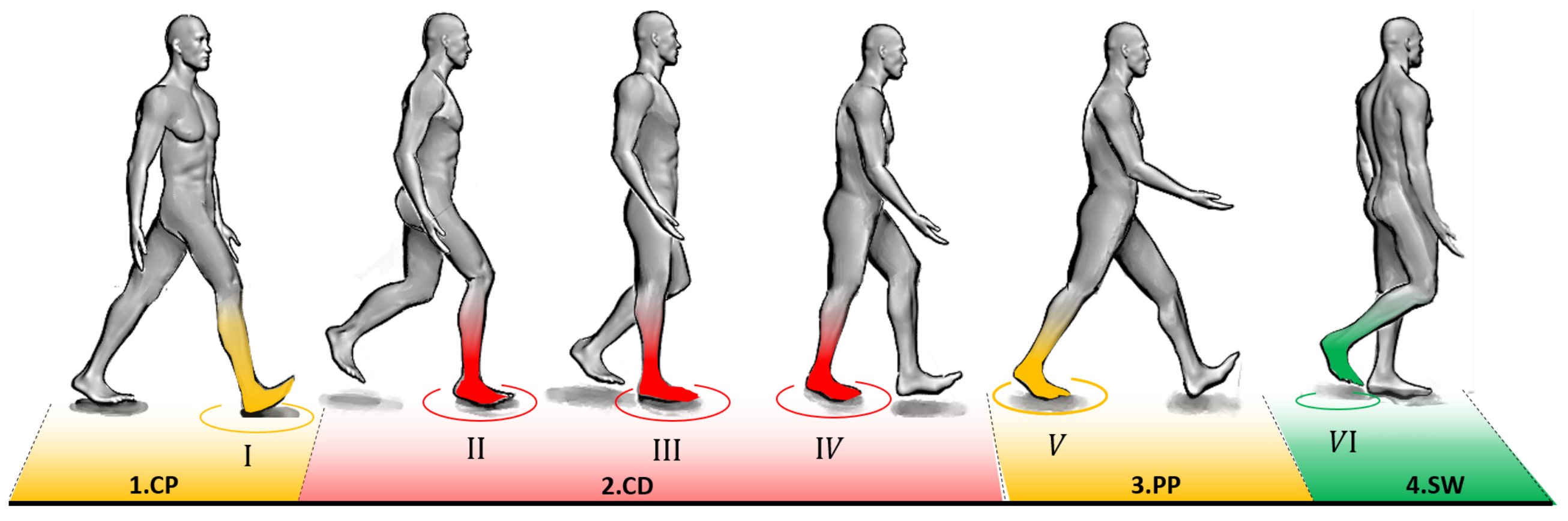
As shown in Figure 2, level-ground walking can be divided into four sub-phases and six states. The human stride was divided into three sub-phases for the stance phase beside the swing phase. The stance sub-phases, 1. Controlled plantar flexion (CP), 2. Controlled dorsiflexion (CD), and 3. Powered plantar flexion (PP), in addition to the swing phase (SW), were used to analyze human ankle behavior during the level-ground walking [28].
1. Controlled plantar flexion: Controlled plantar flexion starts with a neutral ankle position at the heel strike and ends at the foot flat when the foot sole is completely placed on the ground. During CP, the ankle has the task of absorbing the shocks due to weight acceptance. In addition, it modulates CoP, which enables the foot to adapt to the different inclined surfaces [6,29,30].
2. Controlled dorsiflexion: Controlled dorsiflexion starts at the end of the CP and ends at the beginning of the powered plantar flexion. During CD, the ankle reaches its maximum dorsiflexion. This sub-phase can be divided into early dorsiflexion (ED) and late dorsiflexion (LD). During ED, state II to state III, the primary function of the human ankle is to provide smooth rollover and facilitate forward rotation of the shank [31].
During LD, state III to state IV, the ankle tends to store energy in passive element (Achilles tendon) to help propel the foot during the following sub-phase [29,30,32].
3. Powered plantar flexion: Powered plantar flexion starts after CD and ends with toe leaving the ground. During PP, the positive ankle work (generated by the active element, muscle fibers) is used for push-off [32,33,34].
4. Swing: The swing phase starts at toe-off and ends with the heel strike. During SW, the ankle position is modulated until the foot prepared for the next step [17].
2.1.2. Mechanical Representation
The data reported from people without walking-related physical impairments [35] reveal that the net ankle power is negative during CP and ED. Since the ankle is not generating power during these sub-phases, some significant features of the ankle behavior during level-ground walking can be replicated using passive mechanical components such as springs and dampers [11]. The bio-inspired mechanical model was developed (Figure 1a) considering the following mechanical representations:
- During LD, the ankle mechanics can be described as linear springs [37].
2.1.3. Mechanical Design
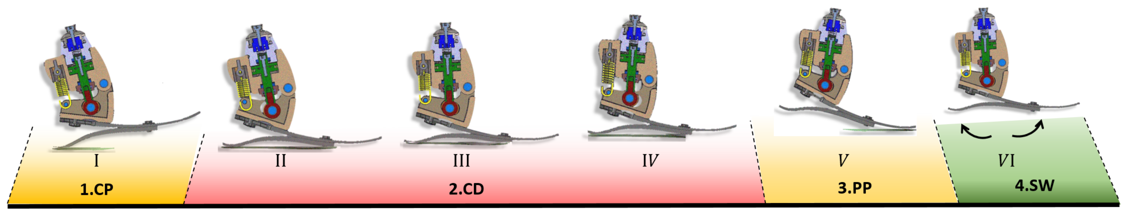
A prosthetic foot was designed by adapting simple physical systems (e.g., spring–damper–mass system) to the developed biomechanical model. Figure 1b shows the critical parts of the H2AP. This prosthesis includes a commercial carbon foot in addition to a hydraulic damper and an extension spring. The carbon foot comprises three interlocked springs: the heel, the midfoot, and the forefoot springs (Figure 1b,c). The passive hydraulic damper is coupled between the pyramid adaptor and the carbon foot. The pyramid adaptor is the standard fixture screwed to the hydraulic damper and coupled with a socket to receive the amputee’s residual shank. The hydraulic damper constituents are:
- Chassis: The chassis includes a hybrid railway mechanism to engage and disengage the piston movement (latching/unlatching the damper) during different moments of the gait cycle. The rotary motion of the artificial ankle is converted to the piston’s reciprocating linear movement by damper arm (Figure 1b). A chassis is screwed to the midfoot spring.
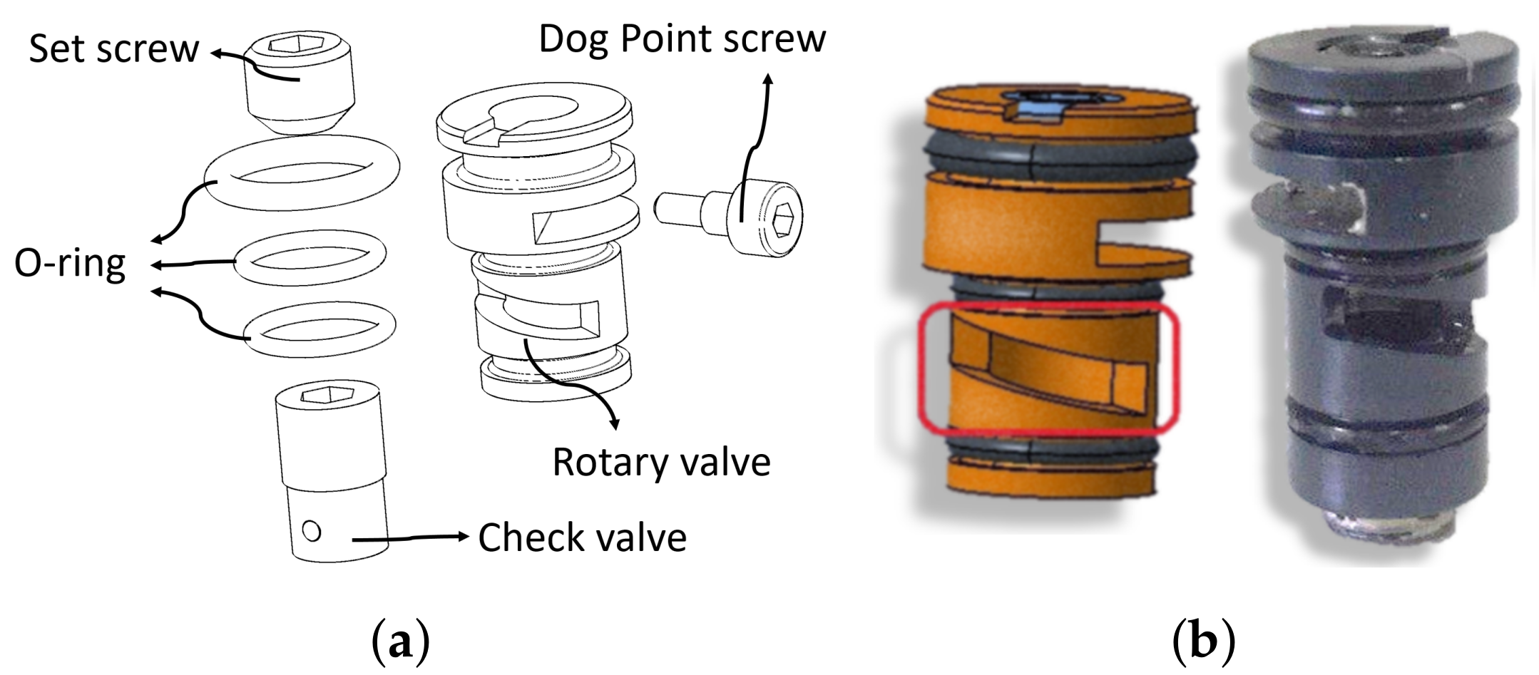
- Hydraulic block: The hydraulic block acts as a housing for the piston and the rotary flow control valves. The piston is reciprocally embedded in the hydraulic block and comprises the upper piston and the lower piston. The piston divides the cylinder, located in the hydraulic block, into upper and lower chambers on the opposite side of the piston. The cover and flange screwed to the hydraulic block to maintain the components’ location inside the hydraulic block.
- Rotary Flow Control Valves: Two rotary flow control valves integrated with check-valves (Figure 3) are manually adjusting the damping coefficient of the plantar flexion (PF) and dorsiflexion (DF) dampers, independently. The upper cylinder chamber connects to the lower cylinder chamber by two independent hydraulic lines. Each hydraulic line has the rotary flow control valve integrated with a check-valve. The presence of the check-valve in each hydraulic line allows the fluid to flow through only one line. Screws are used to keep the rotary flow control valves in their housing and prevent them from being fully closed.
The extension spring (Figure 1b) is placed between the chassis and the hydraulic block. The loose attachment to the chassis is designed to engage the spring during dorsiflexion when the ankle angle becomes smaller than the ankle angle during standing (neutral position).
During early stance (CP and ED, 25% of the gait cycle), a combination of the carbon foot spring and the hydraulic damper is used to provide the benefits (increased RoM and improved rollover dynamics) of the hydraulic prosthetic feet. During late stance (LD and PP, from 25% of the gait cycle to the end of the stance phase), a combination of carbon foot and extension springs is exploited to increase the stored energy. The railway mechanism is contrived to lock the damper while the energy is recycling in the form of plantar flexion push-off work by the springs. The hydraulic damper and extension spring are engaged and disengaged during different sub-phases of the gait cycle, as indicated in Figure 4.
2.2. Experiment-Based Design
The design constraints/limitations are presented in Table 1. These constraints are attributed to the biomechanical behavior of intact gait. The maximum angular velocity, peak pressure profiles, maximum ankle moment from the requisite GRF, and the safety factors are indexes considered for the hydraulic damper design:
- The maximum angular velocity of the artificial ankle joint is determined based on the intact ankle biomechanical behavior during the first 25% of the gait cycle (when the damper is active) [11].
- The maximum allowable pressure specified based on the industry sealing standards [43].
- The ultimate safety factors determined by contemplating the following factors: 1. material, 2. stress, 3. geometry, 4. failure analysis, and 5. reliability [44].
2.3. Hydraulic Damper Specification
Two critical parts of the H2AP (carbon foot and hydraulic damper that are located in series) were simulated using the SIM-Hydraulic toolbox of MATLAB to define the hydraulic damper specification and performance. The carbon foot was modeled by using the torque-angle transfer function proposed in [45]. The hydraulic damper was modeled as a closed-circuit (without accumulator) with an incompressible fluid (Oil- 30W), Figure 5. A double-acting double rod-end piston with a constant piston area and rotary flow control valves were selected for the hydraulic damper circuit since the entry and exit fluid should be the same when the fluid passes between the cylinder chambers. Different symbols are described in Table 2. The mean of the ankle angle, the ankle angular velocity, and the ankle torque reported from 21 intact subjects in level-ground walking (1.1 m/s) [35] were used as the reference data for performing the simulation. The piston mass and area were defined as reported by Parker sealing solutions [43]. The rotary flow control valves’ flow discharge coefficient was determined using the correlating equation recommended for a flow control valve [46]. The check-valves’ maximum passage area was selected based on the standard data related to the fabricated ones [27].
2.3.1. Damper RoM
The reference ankle torque [35] was used as an input to the simulated model. By applying the ankle torque to the carbon foot torque-angle transfer function (Equation (1), [45]), the carbon foot deflection (, the carbon foot contribution in providing ankle angle) can be determined during one stride. Equation (2) shows the torque and angle relation between the carbon foot and hydraulic damper. The hydraulic damper RoM (, the ankle motion provided by the damper) was defined (Figure 6) by comparing the carbon foot deflection and the reference ankle angle ():
2.3.2. Valve Optimal Diameter
The reference ankle torque (Equation (2)) was implemented to the simulated hydraulic circuit to determine the hydraulic damper velocity. The goal is to mimic the ideal damper velocity that can be obtained from the damper RoM via time derivative. The input torque (piston force, Equation (4)) causes a pressure difference between the piston sides (regions 1 and 2 in Figure 5a) as shown in Equation (5) [46]:
Mass flow rate through the flow control valves was measured by the hydraulic flow rate sensor and determined as follows [46]:
Adjusting the plantar flexion and dorsiflexion flow control valves’ diameter can affect the flow rate in the upward and downward movement of the piston separately. The piston velocity was defined utilizing the actual mass flow rate and the piston geometry [46]:
In addition, the correlation equation recommended for a piston velocity was derived by combining Equations (5)–(7) as indicated in Equation (8) [46]:
It is demonstrated in Equation (8) that the piston velocity is related to the piston force by 1. a constant (K) corresponds to fluid properties, the piston geometry, and the hydraulic line diameter, 2. the flow control valve geometry (), and 3. an empirical discharge coefficient (C) that is inherently a function of piston velocity [46].
The hydraulic damper velocity can be acquired from the piston velocity (Equation (8)) and the moment arm that the damper acts on the ankle joint. The comparison between the ideal damper velocity and the hydraulic damper velocity was performed. An iterative process was used to minimize the deviation between these two velocities. The theoretical mass flow rate and the theoretical piston velocity were utilized (the approach is presented in [46]) to determine the flow control valves’ diameter as the initial guess.
In addition, the same comparison between the ideal and the hydraulic damper velocity was performed by hand-tuning the flow control valves’ diameter to find a range of possible diameter for the flow control valves. As long as the mean absolute difference between the hydraulic damper velocity and the ideal damper velocity was less than 30% of the ideal peak velocity, the flow control valves’ diameter is acceptable. The mentioned range of the mean absolute difference was considered to include the ideal velocity from different walking speeds (from slow to moderate speed (50% to 75% PTS, in which PTS is defined as the preferred transition speed between walking and running).
Figure 6 describes the flowchart algorithm belongs to determining ideal damper velocity and hydraulic damper velocity.
2.3.3. Hydraulic Damper Performance
The hydraulic damper performance was evaluated by comparing the simulated ankle torque-angle profile (damper contribution) and the ideal template. The ideal torque-angle pattern derived from the required (ideal) damper RoM (Section 2.3.1) and the input reference torque [35]. The simulated ankle torque-angle relation was obtained by adjusting the optimal diameter for the plantar flexion and dorsiflexion control valves. The simulated damper torque was determined by multiplying the moment arm, the pressure difference, and the piston area (Equations (4) and (5). The simulated damper angle was identified by dividing the piston stroke (Section 2.3.1) to the moment arm (Equation (3)).
2.3.4. Hydraulic Damper Material
The stress analysis of the hydraulic damper’s critical components was carried out to select proper material. The critical forces exerted to the hydraulic damper’s constituents were derived from the maximum operating pressure. The maximum pressure was determined by applying the reference ankle torque [35] to the simulated hydraulic circuit and adjusting the control valves’ diameter to the minimum possible diameter (since they can not be fully closed, Setion Section 2.1.3). In addition, this maximum pressure was measured by the hydraulic pressure sensor within the simulation. The critical components’ stress analysis is elaborated in the following:
- Piston stress: The piston and rod diameters were determined using Equation (5) and the Parker Hydraulics Corporation catalog of metric rod wipers and piston seals [47]. The piston stress was calculated based on the mechanical handbook design [48]. The eye-bolt plunger, the piston thread-locks, and the edge of the piston, where the piston seal is located, identified as the critical parts of the piston. The force exerted to the eye-bolt plunger is equal to the force considered to design .
- Hydraulic block stress: The hydraulic block sizing (the cylinder diameters and thickness and the hydraulic line diameter) was determined to perform the stress analysis. The hydraulic cylinder’s internal diameter was considered to be equal to the piston ring’s diameter (Figure 5b). Then, the lame’s equation (Equation (9), [49]) was utilized to define the outside diameter of the cylinder. In addition, the cylinder thickness was computed using Equation (10):The hydraulic line size was calculated exploiting the standard nomogram (industry standards for sizing hydraulic lines [50]), as presented in Equation (11):The hydraulic bock critical stress was specified with the help of ABAQUS [51]. The ABAQUS model was assumed to be symmetric and pretty simplified due to the complexity of the hydraulic block for partitioning and meshing. The mesh independence study (evaluate the stress convergence) was performed by implementing several simulations with different meshes’ size to determine proper mesh size. The top end (the flange location, Figure 1a) and the hinge joint (the artificial ankle location, Figure 1a) of the block were considered cantilever and pinned support, respectively. The maximum operating pressure (derived within the simulation study) and the critical forces exerted by at the artificial ankle joint served as inputs to the model. Block static stress analysis was performed with a safety factor of 1.88 (Table 1) to include the dynamic conditions (the dynamic pressure and forces applied to the hydraulic block during 25% of the gait cycle).
2.4. Pilot Level-Ground Walking Experiment
A pilot level-ground walking experiment was conducted with one subject having a transtibial amputation (Age: 28 yrs, Mass: 85 kg, Height: 1.79 m) to evaluate the applicability of the proposed hydraulic damper. The study was approved by the ethics committee of Tarbiat Modares University. The subject provided written informed consent before participation. Within this experiment, the subject walked at his preferred walking velocity. During walking, the rotary flow control valves’ diameter (damping level) was adjusted (hand-tuned) to optimize the prosthesis for the subject based on his feedback. The plantar flexion (PF) and the dorsiflexion (DF) damping ratios were set to the low-level and high-level, respectively, and were unchanged throughout the gait cycle. The PF damping regulation can adapt the foot to the slope without slapping the ground and feeling the hard heel. The DF damping adaption can prevent the braking effect and fall forward.
A motion capture system (Vicon-MXT40S, Vicon, 120 Hz, Culver City, CA, USA) was utilized to define ankle angle and ankle angular velocity of the prosthetic limb. Two markers were placed on the toe and the heel of the foot shell, and two additional markers were placed on the artificial ankle joint and the pylon. The ankle angle was determined using the VICON 3D motion analysis software (Vicon Bodybuilder) and the inverse kinematic. In addition, the ankle angular velocity was computed from the ankle angle and the recorded stride period via time derivative. The mean of five strides was calculated and used for the analysis. The H2AP ankle angle (during a gait cycle) and ankle angular velocity (during 25% of the gait cycle) were compared to the reference ankle angle and ideal damper velocity, respectively [52].
The mean absolute difference (MAD) of the ankle angle and the ankle angular velocity during CP and ED was determined for comparing the biomechanics’ similarity between the prosthetic limb and the reference/ideal data. These MAD values were normalized to the prosthetic limb angle excursion and the ideal damper peak velocity, accordingly. In addition, Pearson’s correlation value (Equation (12) [53]) of the ankle velocity was reported to compare the ideal velocity and the simulated/experimental data. Correlation values have a range from 0% to 100%, with 100% indicating a perfect linear correlation. With the H2AP, we aimed for a correlation of close to 100% for the velocity during 0–25% of the gait cycle.
where r and e are reference and experimental/simulated data, sub-index i denotes the data, and is used to show the mean value for the variable x.
3. Results
3.1. Hydraulic Damper Specification
The identified parameters in this section are used in the detailed design of the hydraulic damper.
3.1.1. Damper RoM
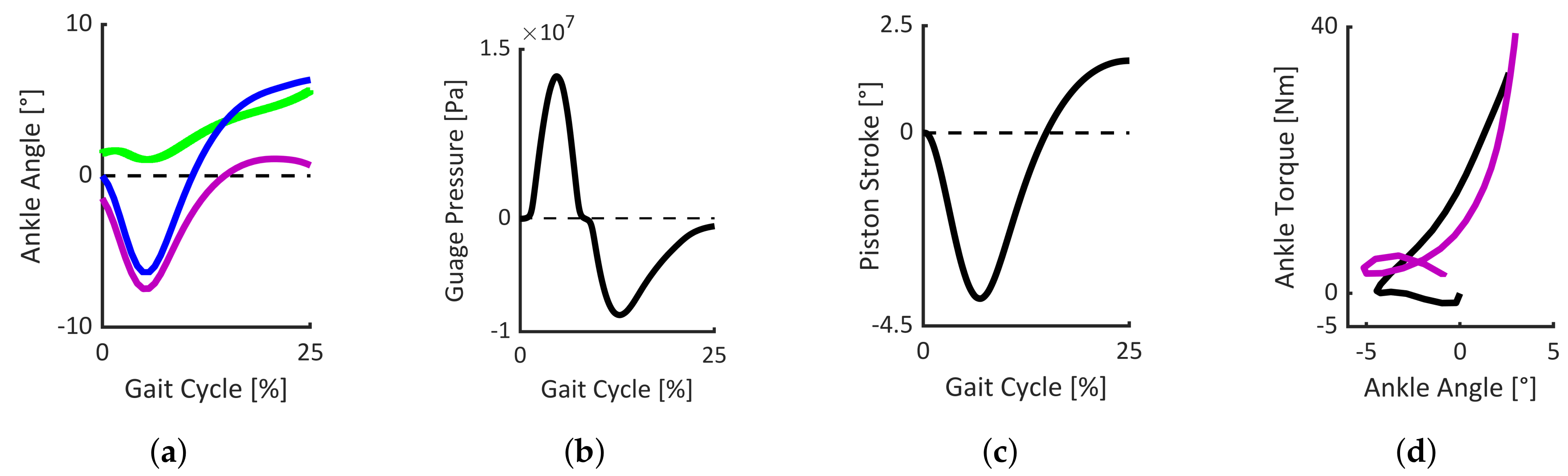
Figure 7a reveals that, during CP and ED of the level-ground walking (1.1 m/s), the damper should provide 8 plantar flexion and 2 dorsiflexion with respect to the neutral position (zero ankle angle). In order to satisfy the range of motion, both observed in Figure 7a and needed to supply adequate deflection in the extension spring (during LD and PP, [27]), the damper RoM is defined to be 10 plantar flexion and 7 dorsiflexion away from the neutral position for the initial design.
Figure 7c reveals that the required piston stroke in the downward and upward direction is 2 mm and 4 mm concerning the neutral position, respectively. Thus, 6 mm is considered for the piston stroke.
3.1.2. Valve Optimal Diameter
It is found from the simulation that the minimum possible diameters are 1.6 mm and 0.4 mm for the plantar flexion and the dorsiflexion control valves, respectively, by considering the acceptable pre-defined mean absolute difference. In addition, the maximum allowable diameter for the plantar flexion valve is 2.8 mm, and it is 1.7 mm for the dorsiflexion control valve.
The hydraulic line diameter of 3 mm is acceptable for designing the hydraulic circuit (Figure 5a) embedded in the fabricated hydraulic block (Section 2.1.3). In theory, if the diameter of the rotary flow control valves exceeds 3 mm, it does not affect the hydraulic circuit flow rate. In addition, as introduced in Section 2.1.3, these valves were designed in a way not to reach a fully-closed position. Hence, 0.1 mm to 3 mm is determined for the rotary flow control valves’ operational diameter.
In the simulated model, the optimal values for the flow control valves were discovered using an iterative diameter adjusting of the control valves (Section 2.3.2). The optimal diameters for the plantar flexion and dorsiflexion rotary flow control valves are found to be 2.5 mm and 0.8 mm, accordingly.
3.1.3. Hydraulic Damper Performance
Figure 7d demonstrates the ideal and simulated ankle torque-angle profiles during 0–25% of the gait cycle. As indicated in Section 2.3.3, only the hydraulic damper is considered to generate these patterns. During CP, when low flexion torque is applied/generated, the outcome of the simulated pattern has deviation compared to the ideal profile. The increased ankle extension torque in ED results in improving the alignment of these two patterns. The mean absolute difference between these two graphs is 11% of the ideal peak torque.
3.1.4. Hydraulic Damper Material
Figure 7b shows that the maximum gauge pressure applied to the hydraulic line is 15 MPa. The piston and cylinder dimensions are determined as: = 39.5 mm, = 29 mm, = 40 mm, = 58 mm, t = 9 mm, and = 3 mm.
Table 3 presents the , the , the , the eye-bolt plunger, and the piston critical stress.
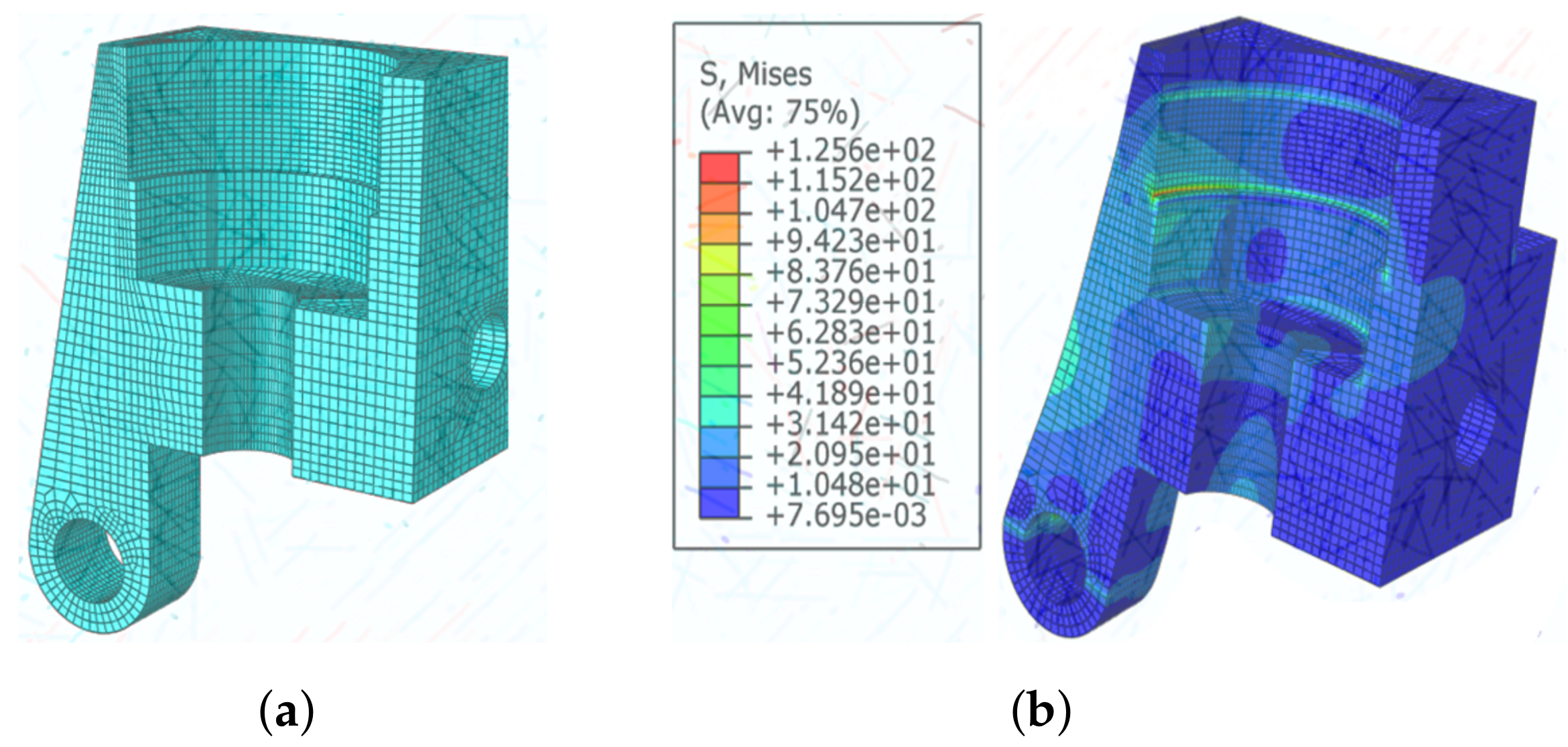
In addition, Figure 8a shows a simplified model of the hydraulic block with a suitable mesh size. Figure 8a shows the hydraulic block stress analysis. The critical stress is located on the housing of the valves and the flange cap thread (Figure 1b). The maximum stress of von Mises is 126 MPa. By applying the block safety factor (Table 1), the minimum yield strength of the selected material should be 302.4 MPa for designing the hydraulic block.
AL_7075_T6, Aluminum alloy was selected to fabricate the H2AP hydraulic damper based on the critical stress defined for each hydraulic damper components (Figure 7b, Figure 8b, and Table 3). The corresponding yield strength and ultimate strength for this material are 485 MPa and 540 MPa. Moreover, low-density, proper mechanical specification, and the convenient machining process are the benefits of this aluminum alloy.
3.2. Pilot Level-Ground Walking Experiment
The ankle angle and the ankle angular velocity comparison between the H2AP and the reference/ideal data are presented in this section. This evaluation is performed to assess the applicability of the H2AP in providing the required RoM and smooth rollover in the level-ground walking. In general, the plantar flexion and dorsiflexion damping coefficients/ratios regulate the rate of ankle rotation and control the required RoM in both directions.
3.2.1. Ankle Angle
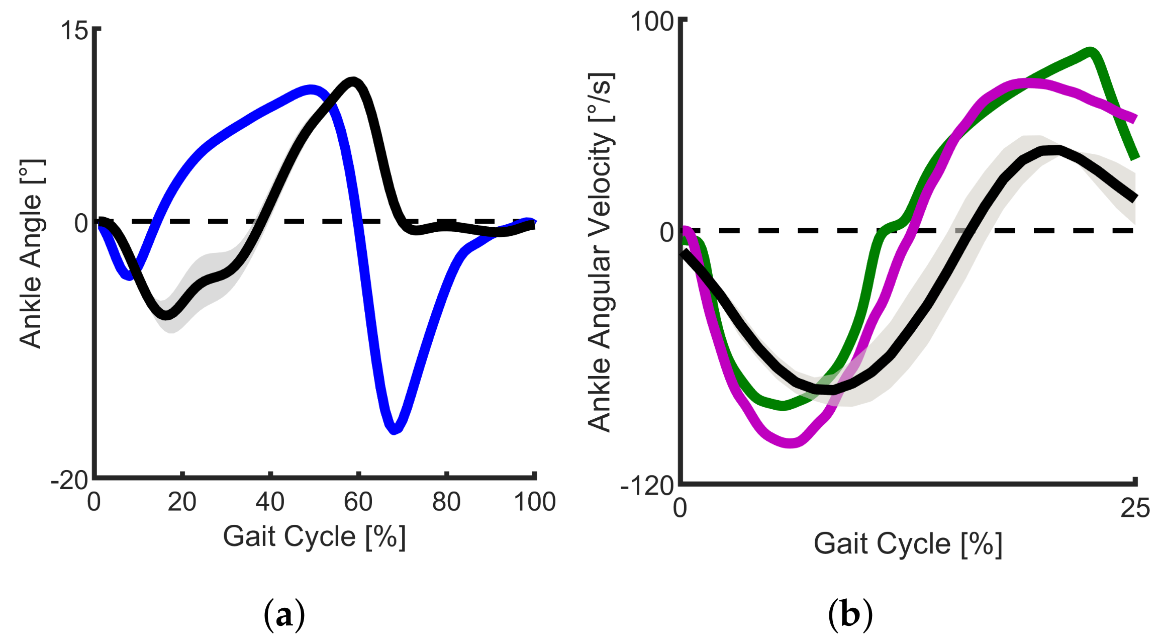
In order to get an insight regarding the functionality of the H2AP in providing the required RoM, the ankle angle during one gait cycle (rather than considering 25% of the gait cycle) is presented. Figure 9a shows the ankle angle comparison between the prosthetic limb and the reference healthy walking data [35]. The ankle angle of the H2AP has a prolonged plantar flexion in CP (extended by 7% of the gait cycle) and a delay in dorsiflexion increase during ED compared to the reference data (reference data dorsiflex faster). While there is a close match between the maximum dorsiflexion ankle angle of the H2AP and the reference data (increased by 6% in the H2AP), there is an excessive plantar flexion in the H2AP (increased by 76%). Due to the passive nature of the H2AP, the ankle angle becomes zero in the swing phase. The mean absolute difference between the prosthetic limb and the reference data are 30% of the H2AP angle excursion.
3.2.2. Ankle Angular Velocity
Figure 9b presents the ankle angular velocity comparison between the H2AP, the simulated hydraulic damper, and the ideal damper velocity derived from the unimpaired reference data (Section 2.3.2). Within the simulated model, Pearson’s correlation value of 99% between the ideal damper velocity and simulated hydraulic damper velocity shows that, in theory, the hydraulic damper can mimic the ideal damper velocity in CP and ED perfectly. However, the simulated model has a lower peak of plantar flexion velocity (83% of the ideal data) and a higher peak of dorsiflexion velocity (increased by 21%) compared to the ideal damper velocity. The mean absolute difference of ankle angular velocity between the ideal damper velocity and the simulated model is 11% of the ideal damper peak velocity.
The experimental data show that the H2AP has a lower peak of both plantar flexion velocity (75% of the ideal data) and dorsiflexion velocity (54% of the ideal data) compared to the ideal one. These deviations result in the mean absolute difference of 32% of the ideal damper peak velocity. Nevertheless, Pearson’s correlation value of 91% reveals that the H2AP can roughly mimic the ideal damper velocity during early stance sub-phases (CP and ED).
4. Discussion
This study aimed at designing a prosthetic ankle-foot to mimic the visco-elastic behavior of an intact ankle during early stance (CP and ED) and provide adequate push-off during late stance (PP). The sound ankle’s physical properties were considered as a reference target to propose a bio-inspired mechanical model. Simple passive mechanical elements such as springs and dampers were adapted to the developed biomechanical model, and a hydraulic prosthesis (H2AP) was designed and fabricated based on this model. The hydraulic dampers (dorsiflexion and plantar flexion damper), the extension spring, and the carbon foot were the three main components of the H2AP.
Hydraulic feet that have an increased range of motion can especially be advantageous at conditions that require an increased range of motion, such as walking on slopes [11]. Within the existing hydraulic prosthetic feet, there is a challenge to develop light and compact design that can provide a safe and smooth rollover during early stance. In addition, there is a need to increase push-off power and energy return during late stance. In this study, we aimed at proposing a novel adjustable damper design for hybrid passive ankle prosthesis to increase RoM. We designed customized rotary flow control valves embedded in the passive hydraulic damper to reduce the prosthesis’s weight and volume. The unprecedented mechanism of the flow control valves eliminates additional constituents (i.e., ball-bearings, dynamic piston seal, and lever-type handle/knob) incorporated in the commercial rotary flow control valves. In addition to the lighter hydraulic damper mechanism, a novel passive mechanism designed for the H2AP that mechanically engages the dampers in 0% to 25% of the gait cycle. In addition, the extension spring (K = 35 N/mm) was added to the system to increase the energy storage and return in the 25% to 60% of the gait cycle.
The highlights and challenges of both the hybrid and hydraulic mechanisms, implemented in the H2AP, are summarized as follows:
- The contrived hybrid railway mechanism (four-bar linkage) latches and unlatches the dampers in different sub-phases of the gait cycle without exploiting any additional elements such as clutches, sensors, motors, and batteries. Since employing dampers disrupts energy-returning during late stance, this mechanism can provide significant advantages compared to other passive hydraulic prosthetic feet.
- The mechanism for converting the ankle joint’s rotary motion to the linear movement of the piston raises the issue of fluid leakage in the hydraulic feet. As the piston should be aligned with the cylinder, the hydraulic sealing parts’ placement has to be carefully designed. Utilizing a curved cylinder can remove the potential of fluid leakage [54].
- The multiple sealing components were considered for the flow control valves, embedded in the hydraulic damper, not only guarantee the valves’ functionality but also provide frictional torque (between the valves and their housing) to restrict any sudden movement of the control valves.
- The design of flow control valves, customized for the hydraulic damper, may result in developing light and optimized prosthetic foot. The usage of flow control valves rather than the piston orifice (hollows carved on the piston surface) results in an ease of valve changing for the maintenance purpose. In addition, this mechanism makes it possible to couple motorized components to the valves and produce a variable damper.
The H2AP was simulated during CP and ED sub-phases to determine the mechanical design parameters and the hydraulic damper’s performance. These parameters were initiated based on the specifications derived from the foot motion patterns in normal level-ground walking (1.1 m/s). Based on the theoretical outcomes from the simulation model, the dampers of the H2AP were designed with the rotary flow control valves that their operational diameter can be adjusted from 0.1 mm to 3 mm. The generated PF and DF damping coefficients can be adapted from 0.1 N.m.s/deg to 6.4 N.m.s/deg. Within the simulation, it can be inferred that the H2AP’ hydraulic damper is capable of emulating the ideal torque-angle behavior (Figure 7d) when the optimal diameter is set for the control valves.
The hydraulic damper’s parameters were modified after the first round of tests by experiments with one subject having a transtibial amputation. The initial flow control valves’ diameter was set to the optimal value derived in Section 3.1.2. For familiarization and to tune the valves of both dampers individually, the subject was asked to walk along the laboratory’s walkway. For sub-optimal damping properties, we expect the following adaptations. While too high damping coefficients should limit the plantar flexion in early stance, too low values could slap the foot on the ground (quick plantar flexion). A too high damping coefficient in the dorsiflexion may result in braking forces and limited the rollover, while a too low damping coefficient could cause reduced safety (due to no resistance) during the rollover. The PF damping was adjusted to avoid experiencing a foot slap and a too stiff heel based on the subject’s feedback. Furthermore, the user reported that the H2AP felt too soft within the first part of the stance. Thus, the DF damping was adjusted in a way to increase the resistance. Walking experiments were performed with the individually tuned damping coefficients (PF and DF damping coefficients were 0.5 N.m.s/deg and 5 N.m.s/deg, respectively).
We compared the H2AP’s ankle angle and ankle angular velocity to the reference/ideal data. Since the hydraulic damper is dominant in providing the ankle velocity (steep slope of damper angle vs. moderate slope of carbon foot angle, as indicated in Figure 7a), the experimental velocity data are considered to associate with the hydraulic damper. We found the addition of the hydraulic damper to the carbon foot can generate the required RoM reported from the intact people (Figure 9a). The correlation value determined in Section 3.2 justifies that the H2AP’s dampers are able to mimic the ideal damper velocity during CP and ED (the period that the damper is active). We believe that the identified angular velocity in the level-ground walking and the advantage in a range of motion of the H2AP demonstrate the benefits of the proposed concept. However, within the level-ground walking experiments, we found deviations between the H2AP ankle angle and the reference data (Figure 9a). The differences for the H2AP exist due to (1) an increased and prolonged ankle plantar flexion in CP, (2) a delay in dorsiflexion increase, (3) an increased ankle dorsiflexion in late stance, and (4) a sudden hump appeared in the ankle angle during ED (21% to 24% of the gait cycle). In the following, we describe the pros and cons of the mentioned differences. In addition, the methods to improve the performance of the H2AP’s dampers are presented:
- The subject preferred to set a low damping coefficient for the PF damper to have a more compliant heel strike. However, this low coefficient can cause an excessive and prolonged negative angle in CP compared to the reference data. Although the pilot experiment was performed based on the damper coefficients’ subject-specific tuning, a higher-viscosity fluid or an increased damping ratio (manually tuned) can be used for the PF damper to increase the resistance during CP.
- A possible reason for the delay in dorsiflexion increase (in ED) may belong to the high damping coefficient for the DF damper. This damping ratio was adjusted to increase resistance (preventing forward fall over), and provide smooth rollover (smooth transition between CP and ED).
- The reason for the increased ankle dorsiflexion during late stance (compared to the initial design, 7 in dorsiflexion) can be due to the incorrect static alignment of the prosthesis in the anterior-posterior direction. A methodological approach (e.g., 3D L.A.S.A.R Posture from Otto Bock) should be used to check and optimize the individual static alignment in anterior-posterior.
- A possible reason that can explain the observed hump in ED may be due to fluid leakage. As the fluid can be lost during the experiment, which can change the H2AP damper’s behavior, the fill level of the dampers should be checked to ensure the intended performance within the tests.
5. Conclusions and Future Work
In this paper, we propose a hydraulic passive damper embedded in the H2AP, Hybrid-Hydraulic Ankle Prosthetic, in order to provide the benefits of hydraulic feet. The data reported from the intact people reveal that, during early stance sub-phases (CP and ED), the net ankle power is negative (dissipative) [55]. The negative power during these sub-phases can be replicated using passive components such as springs and dampers. The main reason for designing a hydraulic damper for the H2AP is to increase RoM and provide a smooth rollover dynamic.
A detailed design of the hydraulic damper was carried out using the parameters derived from the simulation study. Pilot walking experiments were conducted to evaluate the performance of the hydraulic damper. In the first stage, the developed H2AP was tested with the able-bodied human subject to ensure the device’s safety and functionality (the results are not presented in this work). Then, it was tested on a subject with amputation. In addition to light and compact design features, the pilot experiments support the predicted advantages of the proposed device.
The presented results are from an early stage of this research. In order to get a better idea regarding the performance of the proposed device, 1. the experiments should include more subjects, and 2. the users should be allowed to become accustomed and adapted to the new device in future evaluation. In the future, we aim to make the H2AP a semi-active device to enable the prosthetic foot to be used at different walking speeds. As different damping coefficients correspond to different walking speeds (slow, moderate/preference, and fast), the PF and DF damping levels should be adapted for different walking speeds. By utilizing variable damper in a prosthetic foot, methods have to be investigated to improve the damping coefficients’ subject-specific tuning based on the users’ characteristics. Humans in the loop optimization should be taken into account to track the prosthetic behavior online, adjust the damping coefficients, and include the users’ characteristics in the design process.
Author Contributions
Conceptualization, M.M.M., A.N., and M.G.; Funding acquisition, M.M.M. and M.A.S.; Methodology, M.M.M., A.N., M.G., and M.A.S.; Project administration, M.M.M.; Software, A.N. and M.G.; Supervision, M.M.M. and M.A.S.; Writing—original draft, A.N. and M.A.S.; Writing—review and editing, M.M.M. and M.G. All authors have read and agreed to the published version of the manuscript.
Funding
Maziar Ahmad Sharbafi was supported by the German Science Foundation (DFG) under the Grant No.s AH307/2-1.
Acknowledgments
The authors would like to thank Mohammad Reza Dehghani for his support during the designing process. In addition, we would like to thank the Behnam Hajiaghaei faculty of the Iran University of Medical Science and Giti Torkaman, head of the gait analysis laboratory for providing experimental support. We acknowledge support by the German Research Foundation and the Open Access Publishing Fund of Technical University of Darmstadt.
Conflicts of Interest
The authors declare that there is no conflict of interest regarding the publication of this article.
References
- Fletcher, D.D.; Andrews, K.L.; Hallett, J.W., Jr.; Butters, M.A.; Rowland, C.M.; Jacobsen, S.J. Trends in rehabilitation after amputation for geriatric patients with vascular disease: Implications for future health resource allocation. Arch. Phys. Med. Rehabil. 2002, 83, 1389–1393. [Google Scholar] [CrossRef]
- Gardiner, J.; Bari, A.Z.; Howard, D.; Kenney, L. Transtibial amputee gait efficiency: Energy storage and return versus solid ankle cushioned heel prosthetic feet. J. Rehabil. Res. Dev. 2017, 53, 1133–1138. [Google Scholar] [CrossRef]
- Casillas, J.M.; Dulieu, V.; Cohen, M.; Marcer, I.; Didier, J.P. Bioenergetic comparison of a new energy-storing foot and SACH foot in traumatic below-knee vascular amputations. Arch. Phys. Med. Rehabil. 1995, 76, 39–44. [Google Scholar] [CrossRef]
- Kulkarni, J.; Wright, S.; Toole, C.; Morris, J.; Hirons, R. Falls in patients with lower limb amputations: Prevalence and contributing factors. Physiotherapy 1996, 2, 130–136. [Google Scholar] [CrossRef]
- Curtze, C.; Hof, A.L.; Postema, K.; Otten, B. Over rough and smooth: Amputee gait on an irregular surface. Gait Posture 2011, 33, 292–296. [Google Scholar] [CrossRef]
- LaPrè, A.K.; Sup, F. Simulation of a slope adapting ankle prosthesis provided by semi-active damping. In Proceedings of the 2011 Annual International Conference of the IEEE Engineering in Medicine and Biology Society, Boston, MA, USA, 30 August–3 September 2011; pp. 587–590. [Google Scholar]
- Silverman, A.K.; Neptune, R.R. Muscle and prosthesis contributions to amputee walking mechanics: A modeling study. J. Biomech. 2012, 45, 2271–2278. [Google Scholar] [CrossRef]
- Zmitrewicz, R.J.; Neptune, R.R.; Walden, J.G.; Rogers, W.E.; Bosker, G.W. The effect of foot and ankle prosthetic components on braking and propulsive impulses during transtibial amputee gait. Arch. Phys. Med. Rehabil. 2006, 87, 1334–1339. [Google Scholar] [CrossRef]
- Miller, W.C.; Speechley, M.; Deathe, B. The prevalence and risk factors of falling and fear of falling among lower extremity amputees. Arch. Phys. Med. Rehabil. 2001, 82, 1031–1037. [Google Scholar] [CrossRef]
- Mills, P.M.; Barrett, R.S. Swing phase mechanics of healthy young and elderly men. Hum. Mov. Sci. 2001, 20, 427–446. [Google Scholar] [CrossRef]
- Sup, F.; LaPrè, A.K. A semi-active damper design for use in a terrain adaptive ankle prosthesis. In Proceedings of the ASME 2011 International Mechanical Engineering Congress and Exposition, American Society of Mechanical Engineers Digital Collection, Denver, CO, USA, 13–17 November 2011; pp. 1289–1294. [Google Scholar]
- Koehler-McNicholas, S.R.; Nickel, E.A.; Medvec, J.; Barrons, K.; Mion, S.; Hansen, A.H. The influence of a hydraulic prosthetic ankle on residual limb loading during sloped walking. PLoS ONE 2017, 12, e0173423. [Google Scholar] [CrossRef] [Green Version]
- Mauch, H.A. Control Mechanism for Artificial Ankle. U.S. Patent 2,843,853, 22 July 1958. [Google Scholar]
- Moser, D.; Abimosleh, F.; Zahedi, M.S.; Harris, G.; Lang, S.T.; Sykes, A.J. Prosthetic Ankle Joint Mechanism. U.S. Patent 8,740,991, 3 June 2014. [Google Scholar]
- Alimusaj, M.; Fradet, L.; Braatz, F.; Gerner, H.J.; Wolf, S.I. Kinematics and kinetics with an adaptive ankle foot system during stair ambulation of transtibial amputees. Gait Posture 2009, 30, 356–363. [Google Scholar] [CrossRef]
- Poulson, A.M., III; Christensen, R.; Heath, S.; Hsu, H. Hydraulic Prosthetic Ankle. U.S. Patent 8,986,398, 7 August 2014. [Google Scholar]
- Au, S.; Berniker, M.; Herr, H. Powered ankle-foot prosthesis to assist level-ground and stair-descent gaits. Neural Netw. 2008, 21, 654–666. [Google Scholar] [CrossRef]
- New Elan. Available online: http://www.endolite.com/products/elan (accessed on 16 July 2020).
- Motion Foot MX. Available online: http://fillauer.eu/feet/motion-foot (accessed on 16 July 2020).
- Gharini, M.; Mohammadi Moghaddam, M.; Farahmand, F. Investigating the effect of viscoelastic ankle foot prosthesis on below-knee amputee gait cycle: Modeling and simulation. Modares Mech. Eng. 2017, 17, 311–321. [Google Scholar]
- De Asha, A.R.; Johnson, L.; Munjal, R.; Kulkarni, J.; Buckley, J.G. Attenuation of centre-of-pressure trajectory fluctuations under the prosthetic foot when using an articulating hydraulic ankle attachment compared to fixed attachment. Clin. Biomech. 2013, 28, 218–224. [Google Scholar] [CrossRef] [Green Version]
- Johnson, L.; De Asha, A.R.; Munjal, R.; Kulkarni, J.; Buckley, J.G. Toe Clearance When Walking in People with Unilateral Transtibial Amputation: Effects of Passive Hydraulic Ankle. J. Rehabil. Res. Dev. 2014, 51, 429–437. [Google Scholar] [CrossRef]
- De Asha, A.R.; Askew, G.; Buckley, J.G. Mechanical and Physiological Energetics When Using an Echelon Hydraulic Ankle-Foot Device in Unilateral Trans-Tibial Amputees; American Orthotics and Prosthetics Association National Assembly: Las Vegas, NV, USA, 2014. [Google Scholar]
- Vrieling, A.; Van Keeken, H.; Schoppen, T.; Otten, E.; Halbertsma, J.; Hof, A.; Postema, K. Uphill and downhill walking in unilateral lower limb amputees. Gait Posture 2008, 28, 235–242. [Google Scholar] [CrossRef] [Green Version]
- Williams, R.J.; Hansen, A.H.; Gard, S.A. Prosthetic ankle-foot mechanism capable of automatic adaptation to the walking surface. J. Biomech. Eng. 2009, 131, 035002. [Google Scholar] [CrossRef]
- Ward, J.A.; Holgate, R.; Hollander, K. Quasi-Active Prosthetic Joint System. U.S. Patent 9,289,316, 22 March 2016. [Google Scholar]
- Naseri, A.; Mohammadi Moghaddam, M.; Ahmad sharbafi, M.; Gharini, M. Hybrid-Hydraulic Prosthetic Foot. U.S. Patent 62/933,376, 2020; under review,
- Sharbafi, M.; Naseri, A.; Seyfarth, A.; Grimmer, M. Neural control in prostheses and exoskeletons. In Powered Prostheses; Elsevier: Amsterdam, The Netherlands, 2020; pp. 153–178. [Google Scholar]
- Gates, D.H. Characterizing Ankle Function During Stair Ascent, Descent, and Level Walking for Ankle Prosthesis and Orthosis Design. Ph.D. Thesis, Boston University, Boston, MA, USA, 2004. [Google Scholar]
- Palmer, M.L. Sagittal Plane Characterization of Normal Human Ankle Function Across a Range of Walking Gait Speeds. Ph.D. Thesis, Massachusetts Institute of Technology, Cambridge, MA, USA, 2002. [Google Scholar]
- Fatone, S.; Hansen, A.H. Effect of ankle-foot orthosis on roll-over shape in adults with hemiplegia. J. Rehabil. Res. Dev. 2007, 44, 11. [Google Scholar] [CrossRef]
- Hansen, A.H.; Childress, D.S.; Miff, S.C.; Gard, S.A.; Mesplay, K.P. The human ankle during walking: Implications for design of biomimetic ankle prostheses. J. Biomech. 2004, 37, 1467–1474. [Google Scholar] [CrossRef]
- Lipfert, S.W.; Günther, M.; Renjewski, D.; Seyfarth, A. Impulsive ankle push-off powers leg swing in human walking. J. Exp. Biol. 2014, 217, 1218–1228. [Google Scholar] [CrossRef] [Green Version]
- Hof, A.; Geelen, B.; Van den Berg, J. Calf muscle moment, work and efficiency in level walking; role of series elasticity. J. Biomech. 1983, 16, 523–537. [Google Scholar] [CrossRef]
- Lipfert, S. Kinematic and Dynamic Similarities between Walking and Running; Kovac: Hamburg, Germany, 2010. [Google Scholar]
- Gharini, M.; Mohammadi Moghaddam, M.; Farahmand, F. Personalized design of ankle-foot prosthesis based on computer modeling of amputee locomotion. Assist. Technol. 2020, 32, 100–108. [Google Scholar] [CrossRef]
- Bhat, S.G. Design and Development of a Passive Prosthetic Ankle; Arizona State University: Tempe, AR, USA, 2017. [Google Scholar]
- Collins, S.H.; Kuo, A.D. Recycling energy to restore impaired ankle function during human walking. PLoS ONE 2010, 5, e9307. [Google Scholar] [CrossRef] [Green Version]
- Hansen, A.H.; Nickel, E.A. Ankle-Foot Prosthesis for Automatic Adaptation to Sloped Walking Surfaces. U.S. Patent 9,549,827, 24 January 2017. [Google Scholar]
- Zahedi. A Step Change. 2010. Available online: https://www.ingenia.org.uk/getattachment/Ingenia/Issue-45/A-step-change/Zahedi.pdf (accessed on 20 January 2020).
- Nilsson, J.; Thorstensson, A. Ground reaction forces at different speeds of human walking and running. Acta Physiol. Scand. 1989, 136, 217–227. [Google Scholar] [CrossRef]
- Goldberg, S.R.; Stanhope, S.J. Sensitivity of joint moments to changes in walking speed and body-weight-support are interdependent and vary across joints. J. Biomech. 2013, 46, 1176–1183. [Google Scholar] [CrossRef] [Green Version]
- Parker. Parker Sealing Solution. 2015. Available online: https://www.parker.com/literature/Praedifa/Catalogs/Catalog_HydrSeals_PTD3350-EN.pdf (accessed on 20 January 2020).
- Ullman, D.G. The Mechanical Design Process; McGraw-Hill: New York, NY, USA, 1992. [Google Scholar]
- Ziese, A. Effects of Varying Power on Gait with an Active Ankle Prosthesis. Bachelor’s Thesis, Technical University of Darmstadt, Darmstadt, Germany, 2016. [Google Scholar]
- Fox, R.W.; Mc Donald, A.T. Introduction to Fluid Mechanics; John Wiley & Sons: Hoboken, NJ, USA, 1985. [Google Scholar]
- Fluid Power Seal Design Guide, Catalog EPS 5370; Parker Hannifin Corporation: Cleveland, OH, USA, 2007.
- Avallone, U.A.; Baumeister, H.; Sadegh, L. Standard Handbook for Mechanical Engineers; Mechanics of Solids: New York, NY, USA, 1987; Volume 3. [Google Scholar]
- Riley, W.F.; Sturges, L.D.; Morris, D.H.; Riley, W.F. Statics and Mechanics of Materials: An Integrated Approach; John Wiley & Sons: Hoboken, NJ, USA, 2002. [Google Scholar]
- Parker. Three Key Words in Hydraulic Hose Sizing: I.D., Dash Size and Nomogram. 2017. Available online: http://blog.parker.com/three-key-words-in-hydraulic-hose-sizing-id-dash-size-and-nomogram (accessed on 20 January 2012).
- Systèmes, D. ABAQUS, Analysis User’s Manual, Version 6.10-1. Dassault SystÈMes Simulia Corp. 2010, 16, 2017. [Google Scholar]
- Grimmer, M.; Seyfarth, A. Mimicking human-like leg function in prosthetic limbs. In Neuro-Robotics; Springer: Berlin/Heidelberg, Germany, 2014; pp. 105–155. [Google Scholar]
- Stigler, S.M. Francis Galton’s account of the invention of correlation. Stat. Sci. 1989, 4, 73–79. [Google Scholar] [CrossRef]
- Grissom, M. Universal Open Power, Communications, and Control for Assistive Devices; Technical Report; KCF Technologies, Inc.: State College, PA, USA, 2017. [Google Scholar]
- Winter, D.A. Biomechanics and Motor Control of Human Movement; John Wiley & Sons: Hoboken, NJ, USA, 2009. [Google Scholar]
Sample Availability: The datasets generated during and/or analyzed during the current study are available from the corresponding author on reasonable request. |
Figure 1.
Spring and dampers structure in a simple mechanical model (a), CAD representation (b), final fabricated model (c) of the H2AP. The hydraulic block included DF and PF dampers. DF and PF stand for dorsiflexion and plantar flexion, respectively. The carbon foot comprises three interlocked springs. Ankle torque and ankle angle are shown by and , accordingly.

Figure 2.
Sub-phases and states during the gait cycle used to obtain the ankle behavior in the level-ground walking.
Figure 2.
Sub-phases and states during the gait cycle used to obtain the ankle behavior in the level-ground walking.

Figure 3.
Exploded view (a) and final CAD and fabricated model (b) of the proposed rotary flow control valve embedded in the H2AP hydraulic damper.
Figure 3.
Exploded view (a) and final CAD and fabricated model (b) of the proposed rotary flow control valve embedded in the H2AP hydraulic damper.

Figure 4.
Working principle of the H2AP during the gait cycle.

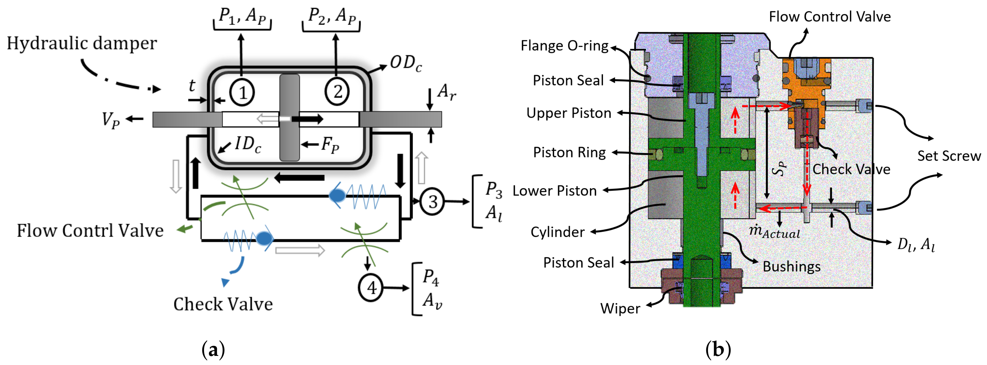
Figure 5.
Closed-circuit symbol (a) and CAD representation (b) of the hydraulic damper. Rod area, piston area, piston force, and piston velocity are shown by Ar, AP, FP, and VP, accordingly. The flow control valve’s area (Av) regulates the PF (black arrow) and DF (white arrow) flow rate () and causes a pressure difference between the piston sides (P1 − P2). The cylinder thickness, outer diameter, and inner diameter are represented by t, ODc, and IDc, correspondingly. Dl and SP stand for the hydraulic line diameter and the required piston stroke, respectively.

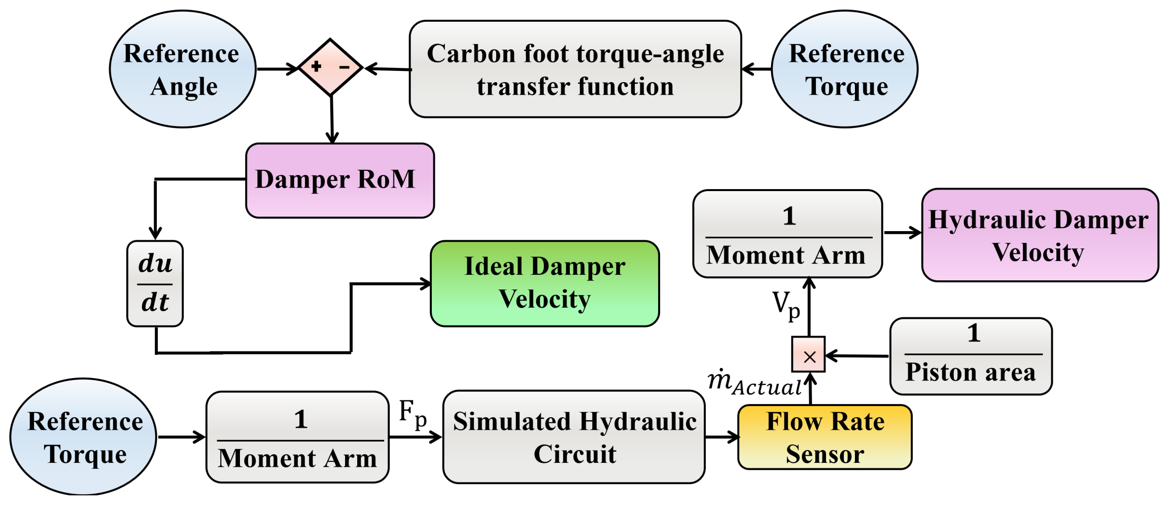
Figure 6.
The flowchart algorithm for determining the rotary flow control valves’ diameter range for operating in the simulated hydraulic circuit and optimal diameter to adjust optimal flow rate.
Figure 6.
The flowchart algorithm for determining the rotary flow control valves’ diameter range for operating in the simulated hydraulic circuit and optimal diameter to adjust optimal flow rate.

Figure 7.
Carbon-foot deflection (green, virtual rotational spring at the H2AP artificial ankle joint) and required damper RoM (purple) derived from the sound ankle angle pattern (blue, 1.1 m/s, [35]) (a), hydraulic line gauge pressure by adjusting the control valves’ diameter to the minimum possible diameter (b), piston stroke (c), and ankle torque-angle profile (d) during the first 25% of the gait cycle. The simulated H2AP, reference data, and ideal damper data are colored in black, blue, and purple, respectively.

Figure 8.
A simplified model associated with a suitable mesh size (a) and stress analysis (b) of the hydraulic block. The stress analysis was performed using ABAQUS.
Figure 8.
A simplified model associated with a suitable mesh size (a) and stress analysis (b) of the hydraulic block. The stress analysis was performed using ABAQUS.

Figure 9.
Subject with transtibial amputation level-ground walking experiments using the H2AP, including ankle angle and ankle angular velocity. Prosthetic limb data include the mean and standard deviations of multiple strides. (a) comparison of the ankle angle during one gait cycle between the prosthetic limb (black, 1.01 m/s) and the reference data (blue, 1.1 m/s). The zero angle is the ankle angle at heel strike; (b) comparison of the ankle angular velocity during 25% of the gait cycle between the prosthetic limb (black, 1.01 m/s), simulated model (green, 1.1 m/s), and ideal damper velocity (purple, 1.1 m/s).


Table 1.
Design limitation.
| Criterion | Definition | Value |
|---|---|---|
| Maximum allowable pressure | 20 [MPa] | |
| Maximum ankle moment | 1.2 | |
| Vertical ground reaction force | 1839 [N] | |
| Horizontal ground reaction force | 368 [N] | |
| Maximum angular velocity | 150 | |
| Hydraulic block safety factor | 2.4 | |
| Hydraulic damper components safety factor | 1.88 |
Table 2.
System variables.
| Symbol | Description | Unit | Symbol | Description | Unit |
|---|---|---|---|---|---|
| Ankle torque | [Nm] | Fluid density | [] | ||
| Artificial ankle angle | [rad] | Cylinder inner diameter | [mm] | ||
| Carbon foot deflection | [rad] | Cylinder outer diameter | [mm] | ||
| Damper angle | [rad] | t | Cylinder wall thickness | [mm] | |
| Damper arm | [mm] | Hydraulic line Area/Diameter | []/[mm] | ||
| Piston stroke | [mm] | Control valve Area/Diameter | []/[mm] | ||
| Piston Force | [N] | Piston/Rod area | [mm] | ||
| Piston Velocity | [] | Actual mass flow rate | [] | ||
| Piston pressure in region 1,2 | [Pa] | C | Empirical discharge coefficient |
Table 3.
Hydraulic damper’s components stress.
| Critical Components | Critical Stress (Von Mises) [MPa] | Critical Stress (Considering Safety Factor) [MPa] |
|---|---|---|
| 263.5 | 495 | |
| 223 | 419 | |
| 190.5 | 398 | |
| Eye_bolt plunger | 156.1 | 293.5 |
| Piston | 133.6 | 251.2 |
© 2020 by the authors. Licensee MDPI, Basel, Switzerland. This article is an open access article distributed under the terms and conditions of the Creative Commons Attribution (CC BY) license (http://creativecommons.org/licenses/by/4.0/).
Share and Cite
MDPI and ACS Style
Naseri, A.; Mohammadi Moghaddam, M.; Gharini, M.; Ahmad Sharbafi, M. A Novel Adjustable Damper Design for a Hybrid Passive Ankle Prosthesis. Actuators 2020, 9, 74. https://0-doi-org.brum.beds.ac.uk/10.3390/act9030074
AMA Style
Naseri A, Mohammadi Moghaddam M, Gharini M, Ahmad Sharbafi M. A Novel Adjustable Damper Design for a Hybrid Passive Ankle Prosthesis. Actuators. 2020; 9(3):74. https://0-doi-org.brum.beds.ac.uk/10.3390/act9030074
Chicago/Turabian StyleNaseri, Amirreza, Majid Mohammadi Moghaddam, Mohammad Gharini, and Maziar Ahmad Sharbafi. 2020. "A Novel Adjustable Damper Design for a Hybrid Passive Ankle Prosthesis" Actuators 9, no. 3: 74. https://0-doi-org.brum.beds.ac.uk/10.3390/act9030074
Note that from the first issue of 2016, this journal uses article numbers instead of page numbers. See further details here.