Static Characteristics of a Tilting Five-Pad Journal Bearing with an Asymmetric Geometry


1
Department of Mechanical Engineering, The University of Danang—University of Science and Technology, 54 Nguyen Luong Bang Street, Danang, Vietnam
2
Department of Mechanical Engineering, Politecnico di Milano, Via La Masa 1, I-20156 Milan, Italy
*
Author to whom correspondence should be addressed.
Actuators 2020, 9(3), 89; https://0-doi-org.brum.beds.ac.uk/10.3390/act9030089
Submission received: 10 August 2020
/
Revised: 14 September 2020
/
Accepted: 15 September 2020
/
Published: 18 September 2020
(This article belongs to the Special Issue Actuators for System Identification, Vibration Analysis, and Control)
Abstract
:In this paper, static characteristics of a tilting five-pad rocker-backed journal bearing with an asymmetric geometry, i.e., different clearance for each pad, are investigated. A thermo-elasto-hydrodynamic (TEHD) model considering the elasticity of the pad and pivot is used for the simulation. The pivot stiffness of each pad obtained by experiment is also introduced in the model. The experimental tests were carried out on a tilting pad journal bearing (TPJB) with a nominal diameter of 100 mm and a length-to-diameter (L/D) ratio of 0.7 with load-between-pad (LBP) and load-on-pad (LOP) arrangements. Several analyses, including numerical simulations and experimental measurements, are implemented in order to obtain the static behaviors of the tilting-pad bearing under variations of rotational speed, amplitude and direction of applied static load, such as clearance distribution profile, static eccentricity, temperature and pressure distribution. The results show that the effect of asymmetric geometry on the static characteristics is not negligible.
1. Introduction
Journal bearings are widely used to support the load in the direction normal to the rotating shaft and widely investigated in the literature, such as in the comprehensive book about hydrodynamic lubrication by Hori [1]. Among sliding bearings, this kind of bearing is the most popular one. Hydrodynamic journal bearings are frequently instrumented in rotating machines for supporting loads. Hence, it is necessary to identify the actual or expected operating conditions of the bearings in the process of machine design. These working conditions can be investigated by simulation and experiment. Hydrodynamic journal bearings can be found in steam turbines, electric motors, generators, pumps, compressors, internal combustion engines and so on, even though rolling element bearings are widely used.
Titling pad journal bearings (TPJBs) are commonly equipped in high rotational speed machinery like steam and gas turbines. This is generally thanks to two special characteristics of this bearing, namely stability at high rotational speeds and a high tolerance of misalignment. Owing to the hydrodynamic pressure, the pad can tilt and a converging zone is generated between the pad and the shaft. The pad tilting depends on the bearing operation parameters, such as bearing load and rotational speed. In comparison with plain cylindrical journal bearings, these bearings consist of more moving mechanical elements, leading to a potential chance of component damage. Additionally, they are more complicated to study. The shaft center moves along the {X, Y} axes which gives two degrees of freedom (DOF). In addition, each pad has at least three DOF (one rotation and two deflections). Hence, the total number of DOF in the TPJB is 2+3Npads. In the same case, the pad can also tilt in the axial direction.
Year after year, numerous studies have investigated the calculation of and experiments on all behaviors of TPJBs in both load-between-pad (LBP) and load-on-pad (LOP) arrangements [2,3,4,5]. The hybrid lubrication methodology for TPJBs was introduced to the model [2]. This study showed that by using the hybrid lubrication, the dynamic performance of a system shows a minor enhancement compared to that of using passive lubrication. Another study investigated the theoretical and experimental operating characteristics of TPJBs with hydrostatic, hybrid and hydrodynamic conditions [5]. To improve the prediction for TPJB behaviors, rotor-pad transfer functions have been introduced to the analytical model [6,7].
Various studies have been conducted to evaluate the temperature distribution of bearings. The pad temperatures and oil film thicknesses of two full-sized three-pad TPJBs were experimentally studied [8]. Ten K-type thermocouples and six proximity probes were used to measure the pad temperature and oil film thickness, respectively. The results show that the maximum temperatures of all pads among the tests of bearing #1 and bearing #2 were about 91 °C and 94 °C with a shaft speed of 1500 rpm, which are about 4 °C lower than the theoretical results. Additionally, the film thicknesses at the pivot position of the two bearings were about 218 μm and 178 μm, respectively.
Zhao et al. [9] proposed a methodology named temperature collaborative monitoring using characteristic points to measure TPJB temperature. In this method, the characteristics of lubrication for TPJBs were analyzed, especially the distribution of temperature and pressure and oil film thickness. A similar pad temperature was found at the steam end and the excitation end. The authors concluded that the temperatures at both sides strongly depend on the rotational speed.
A study was conducted to compare pad temperature and the power loss of the system using the leading edge groove TPJB and the conventional one with and without a seal tooth [10]. Pad temperatures and power losses versus shaft speed, oil flow and applied static load were evaluated. The authors concluded that TPJBs with a seal tooth have a higher pad temperature and power loss than bearings without a seal tooth. It was also found that, among the test bearings, the smallest power loss and lowest pad temperature occur for the conventional bearing without a seal tooth.
Cooled pads in five-pad TPJBs instrumented with several internal channels were presented in [11]. The fluid system was circulated for the purpose of external cooling. The tribological features of lubricating oils used in the process industry were optimized in [12]. In this study, viscosity, temperature distribution and the thickness of the oil film were input parameters for the optimal lubricating oil characteristics definition.
Additionally, the tribological performance for journal bearings was tested by applying a bio-based lubricant method [13]. The effect of lubrication oil on the performance of journal bearings was studied by some authors [14,15]. The gaseous phase areas of journal bearings under flooded and starved lubrication conditions were theoretically studied by means of the computational fluid dynamics of a two-phase flow [16]. A thermo-hydrodynamic model was developed in [17], in which the pressure and temperature distributions in the oil film were calculated together. The results also show that the temperature increased with an increase in the rotational speed, owing to the shear rate of the oil film. This effect was also experimentally investigated and presented in [18]. The influence of the heat convection coefficient on the predicted performance of a large tilting pad thrust bearing was investigated in [19]. However, the authors found that no satisfactory agreement between the measurements and predictions for all analyzed parameters was obtained and no clear rule could be defined. Elinget et al. [20] proposed a thermal network model which added the surface temperature of the bearing housing and shaft and the oil temperature at the inlet of the bearing to obtain more accurate predictions of the rotor-bearing response.
Wilkes et al. [21] discussed the effect of pad and pivot flexibility on predicting static and dynamic characteristics of TPJBs, and summarized the discrepancy between the measured and calculated dynamic coefficients as a function of excitation frequency. A clearance profile with a pentagonal shape as a function of operating temperature was plotted. The experimental results show that the hot clearances were nearly 30% smaller than the cold ones and were inversely proportional to the pad surface temperature. The thermal effects on the performance of TPJBs and pressure distribution were investigated in [22,23].
The impacts of deflection of a pivot on the performances of journal bearings fabricated with rocker-backed and ball-socket pivots was studied in [24]. This paper presents a thermos-hydrodynamic (THD) model in which the pivot stiffness was obtained using the Hertzian contact theory to predict the static and dynamic characteristics of journal bearings. Yingze et al. [25] presented the nonlinear dynamic behaviors of TPJBs with elastic pivots. It was found that the pivot stiffness, preload factors and pre-tightening force have significant effects on the TPJB performances.
While numerous studies of TPJBs used the Hertz theory to calculate the pivot stiffness, several projects performed experiments to estimate the stiffness value. However, in these studies, all pad pivots were assumed to have similar stiffness due to the arrangement of the test rig. In this research, the load can be applied in any direction thanks to configuration of the test rig, which will be presented in a later section. Thanks to this method, the stiffness of each pad pivot can be easily obtained.
The effect of geometry on the performance of TPJBs was studied in [26,27]. A lot of projects have only focused on the LOP or LBP configurations, or both. On the contrary, research about the influence of load direction on the TPJB performances is still limited, and numerous studies are only focused on the theoretical investigation.
In this paper, static characteristics of a tilting five-pad rocker-backed TPJB with an asymmetric geometry are investigated. The thermo-elasto-hydrodynamic (TEHD) model considers the pad and pivot flexibility in which the pivot stiffness of each pad is estimated by experimental activities. Then, some experimental tests are carried out for comparison with the analyses. Results regarding the clearance distribution profile, static eccentricity as a function of rotational speed, temperature and pressure distribution as a function of rotational speed, amplitude of static load and load direction are discussed.
2. Bearing Modeling
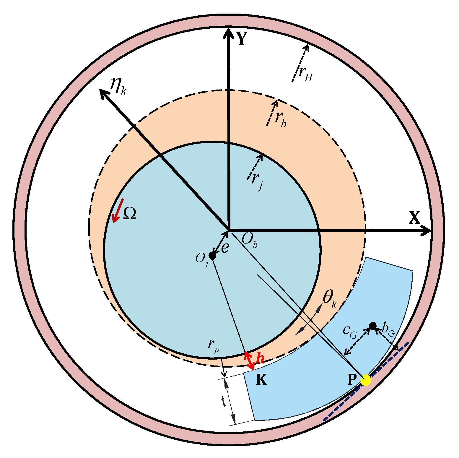
The TEHD model of TPJBs was developed and validated by experimental data in [28] and was improved for the elastic pivot stiffness and thermal feature, as partially done in [29] for two-axial groove journal bearings. Figure 1 shows the scheme of a pad-shaft system in a rocker-backed TPJB, where Ob and Oj are the center of the bearing and the shaft, respectively. Only the displacement of point P in the radial direction is considered for the pivot flexibility, while the tangential displacement is neglected. The pad tilts about the line contact with angle (see Figure 1). So, the vector of the DOF of the system is:
where xs and ys are the shaft center position and and represent the tilt angle and the radial movement of the k-th pad, respectively.
It was found that the effect of the flexibility of the pivot along the direction in the prediction of the performances of TPJBs is very important. The pivot stiffness estimated from the Hertz contact theory is always higher than that obtained by experiments, especially for rocker-backed bearings [29]. In order to improve the numerical simulation, the pivot stiffness estimated by experiment is introduced to the code. The experimental procedure for the stiffness pivot calculation of each pad has been described in detail in [29].
The pressure distribution of each oil film is obtained by using the well-known Reynolds equation:
where h and p are the thickness and pressure distribution in the fluid film, are the dynamic viscosity and density of the oil and x, z are the tangential and axial direction.
To solve Equation (2), the following assumptions are used: laminar flow, Newtonian fluid, negligible inertia forces, insignificant fluid compressibility, negligible slippage between the solid surface and the fluid and constant pressure in the film thickness.
The variables and present the velocity components of the shaft and the pads, respectively [1]. Note that represent the velocity component along the tangential direction and radial direction, respectively.
In a steady-state condition, , and . The energy equation of each oil film can be calculated as:
The viscosity and density of the lubricating oil are:
ISO VG46 oil was used to lubricate the bearing in this research and its properties are listed in Table 1.
A finite difference method was used to solve the Reynolds equation. At node of the mesh grid, the pressure is as follows:
A simple thermal model with 2D control volume [30] was applied for the estimation of the temperatures and viscosities of fluid in the bearing. An adiabatic condition was applied to the shaft surface and the average oil temperature along the radial direction was supposed to be constant. The temperature distribution in the oil film was applied to the active surface of the 3D thermal model of the pads.
The temperature Tp of the center of each control volume with dimensions and is a function of the temperatures of the four edges of the control volume and the previous value of the iteration for temperature Tp0:
The term E depends on the discrepancy between the “in” and “out” flows of lubricant of the control volume and is given by:
where:
The parameters SC, SP and the intensity of the viscous heating S are obtained by:
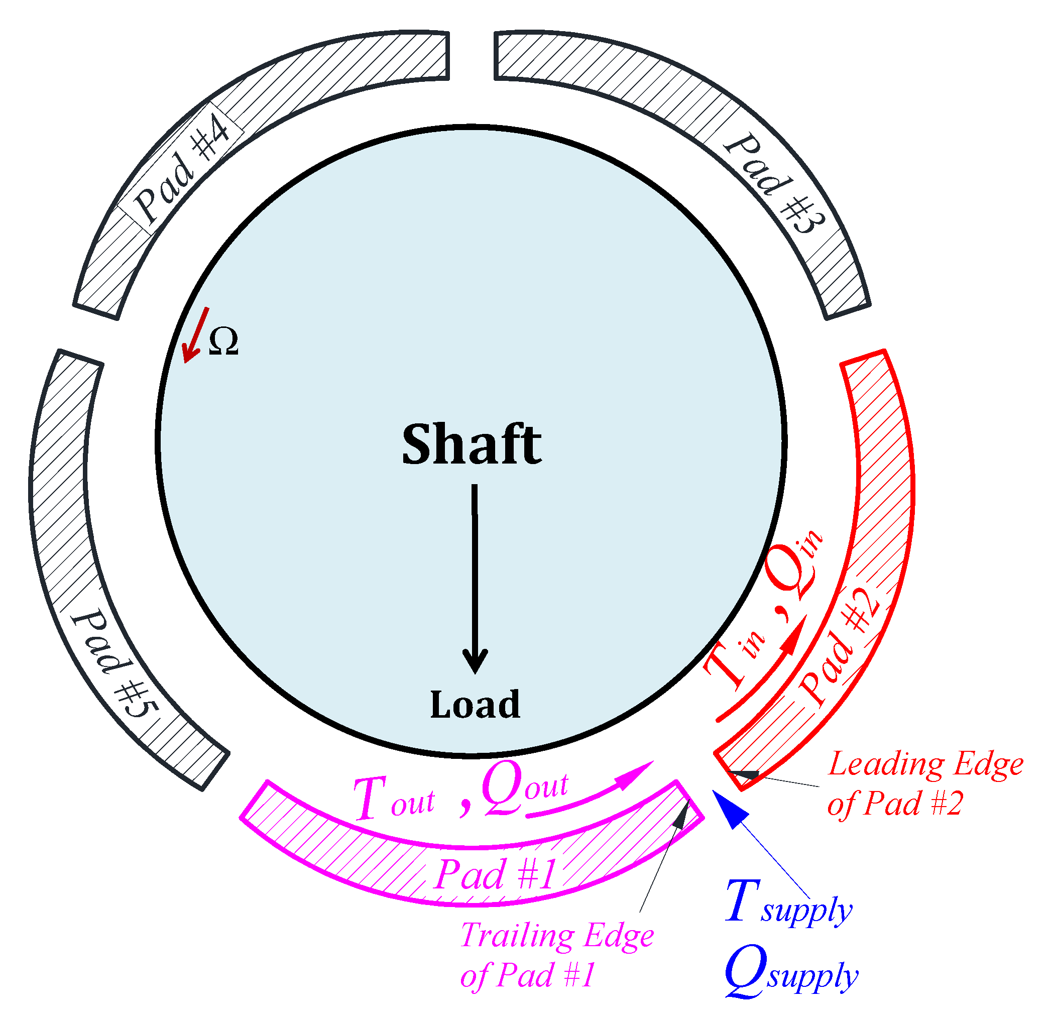
In this model, the thermal power is generated by the viscous shear stress and the effect of adjacent pads is taken into account by the hot oil carry-over coefficient mT, as shown in Figure 2.
Therefore, the inlet oil temperature is:
where the supply temperature is and . Toutlet is the average oil film temperature at the pad trailing edge and is achieved by taking into account the heat flux at the trailing edge:
Additionally, 3D finite element analysis is used to evaluate pad deformation because of the pressure distribution and the thermal expansion. Then, these pad deformations are introduced in the change in oil film thickness. The temperature distribution in the pad is (at the steady state):
where is the material thermal conductivity. The deformation of the pad u owing to thermal and mechanical stresses considering an isotropic material is given by:
where C is the tensor of mechanical properties and E, , represent Young’s modulus, the thermal expansion coefficient and Poisson’s ratio of the material, respectively.
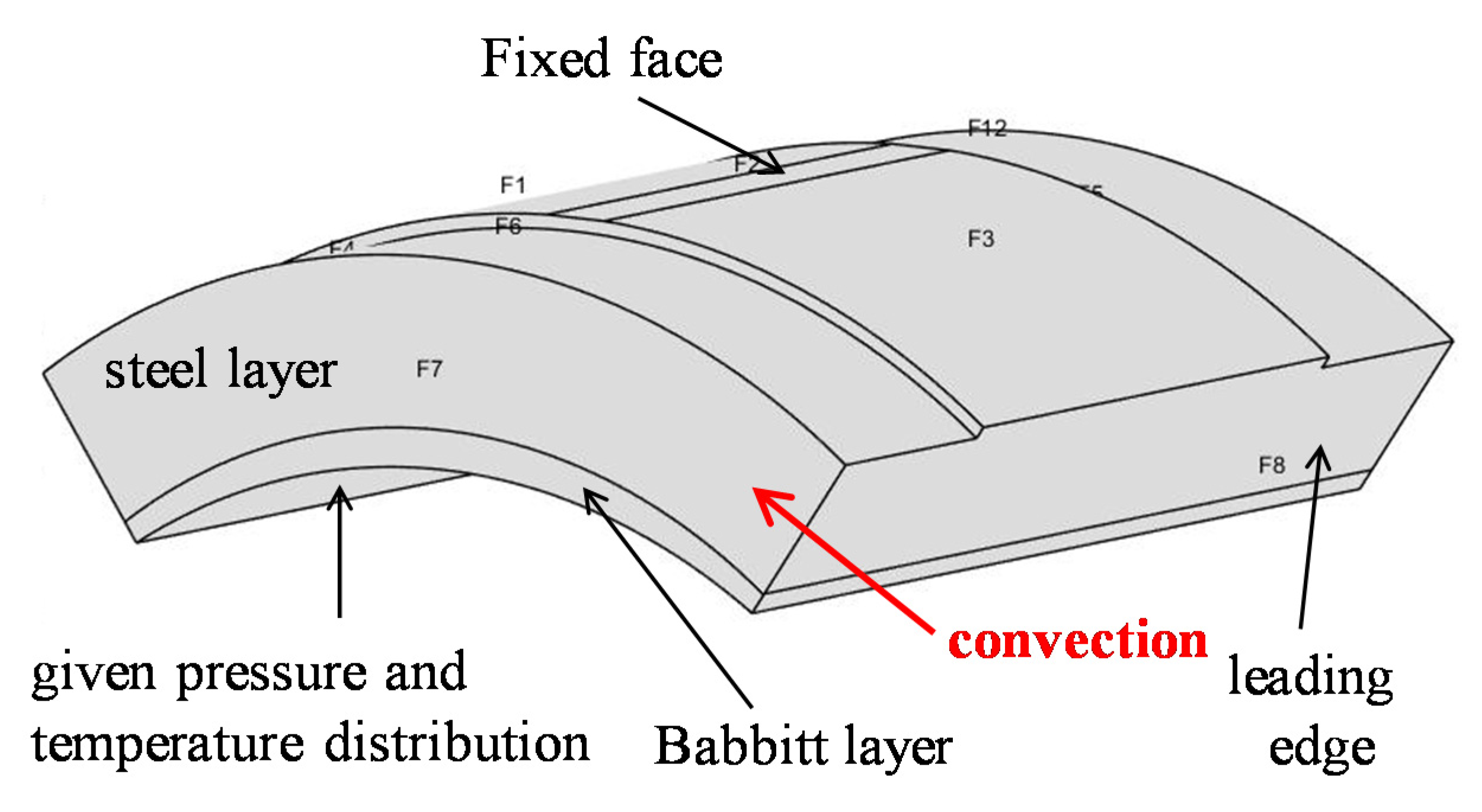
Readers are strongly recommended to refer to [11,29] for a detailed description of the model. Each pad consists of two different parts: a base part (steel) and an anti-friction layer (Babbit metal with a thickness of 3 mm). The properties of the two materials are listed in Table 2.
In this study, a convection boundary condition with a constant coefficient of q = 50 W/(m2·K) is applied on the pad surfaces contacting lubricating oil at supply temperature (Tsupply = 40 °C and qair = 20 W/(m2·K)) in order to evaluate the distribution of the pad temperature. The constant convection coefficient q = 50 W/(m2·K) was also used in some previous publications [11,29,31,32]. Actually, this value is not uniform at the pad peripheries and it changes with the conditions of the oil flow around the pad [19]. For the estimation of the pad deformation, the Dirichlet boundary condition with null displacement is assumed for the upper surface of the pad face F2 (see Figure 3), corresponding to the pivot part. The boundary conditions used in the model of the pad are listed in Table 3.
As already stated, numerous studies of TPJBs assumed the nominal dimension for all pads. Unfortunately, due to an error in manufacturing, the actual dimensions of the pads are different from each other. The effect of the manufacturing/assembly error on bearing and system was highlighted in [32,33]. Based on the bearing geometry estimation methodology which was described in [28], the actual pad thickness can be obtained.
The values of pad thickness, bearing assembly clearance and preload factor of the nominal bearing and real bearing are provided in Table 4.
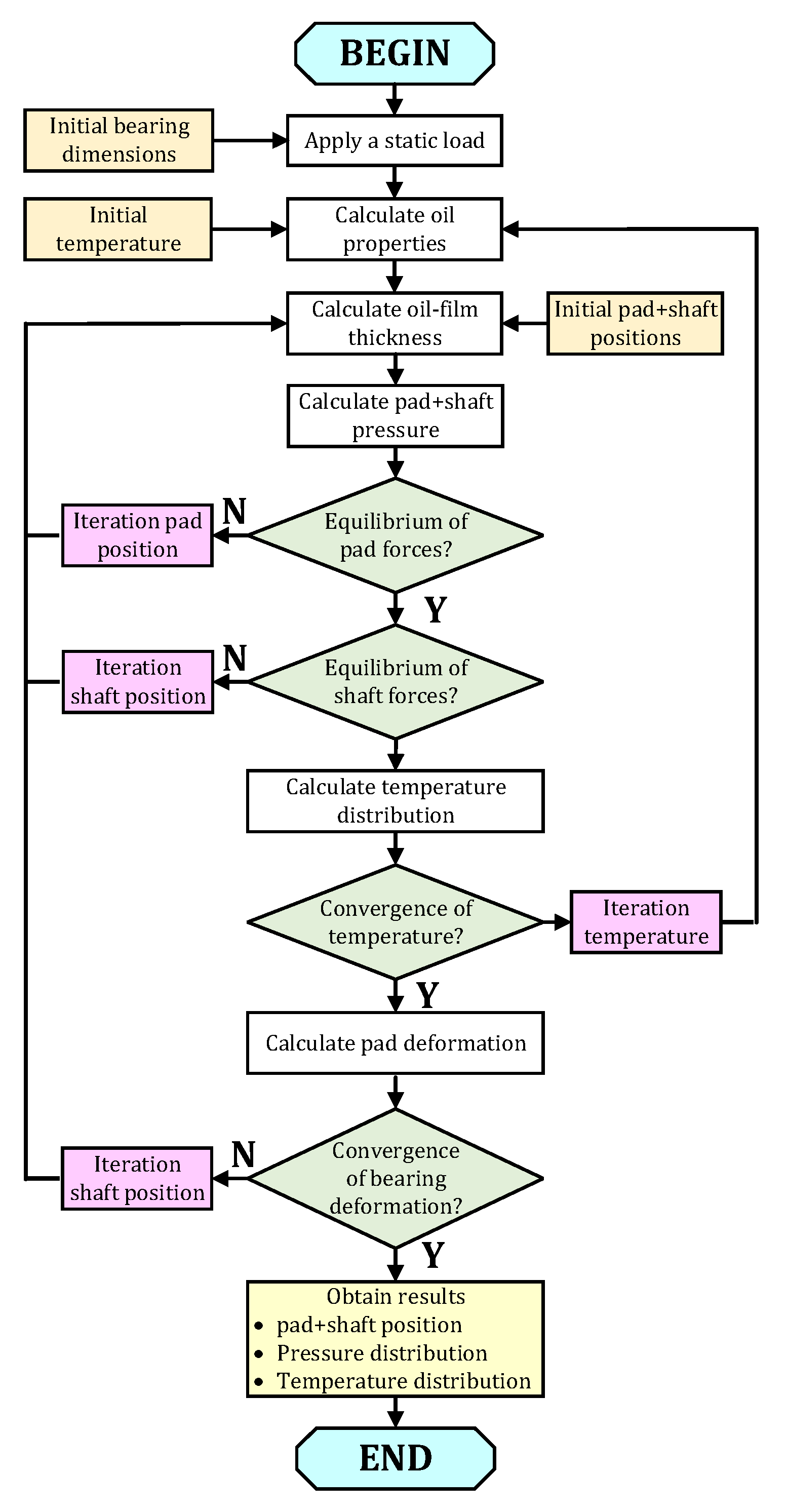
In this model, the optimization toolbox in Matlab is applied for finding the equilibrium position of the pads and shaft. Additionally, the Partial Differential Equation Toolbox is introduced to the 3D structural mechanics and thermal models to calculate the deformation of each pad and the temperature distribution, respectively. The main program flowchart for the TEHD model in this paper is shown in Figure 4.
3. Test Rig and Bearing under Test
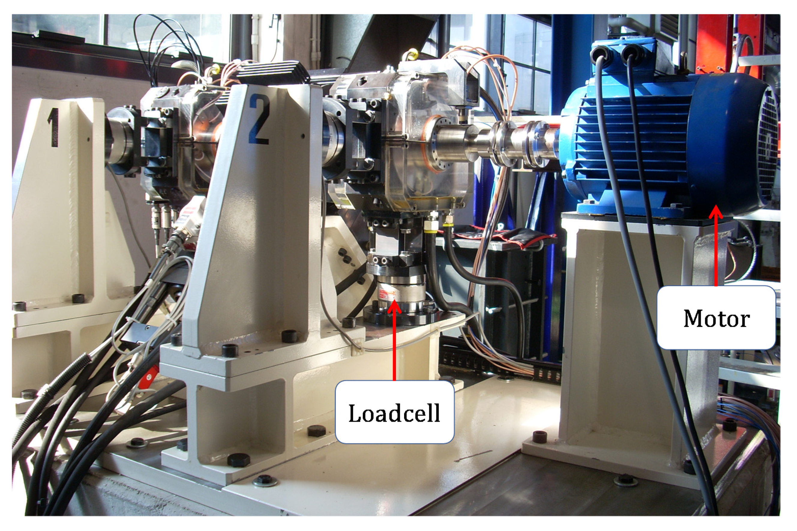
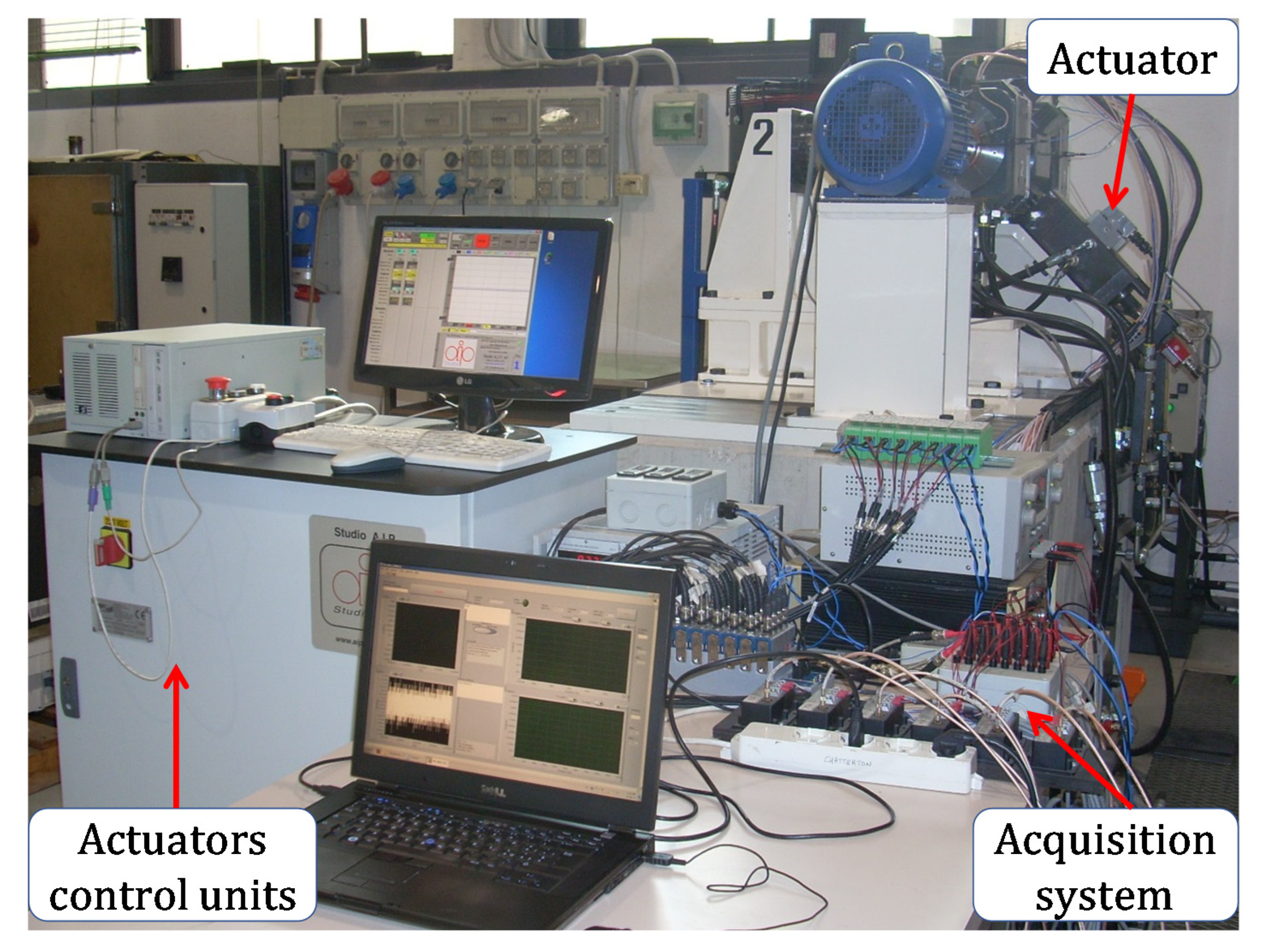
A picture of the test rig used to perform the experimental tests is shown in Figure 5. A detailed description of this test rig was presented in [28]. Two identical five-pad TPJBs support the shaft but only one bearing (including the housing support and the bearing ring) is fully instrumented by necessary sensors, such as load cells, proximity probes, temperature probes and accelerometers. The bearing housings are structured so that the bearings can be configured in the LOP or LBP arrangement. Two orthogonal 20 kN load cells are installed in each bearing housing in the horizontal and vertical direction.
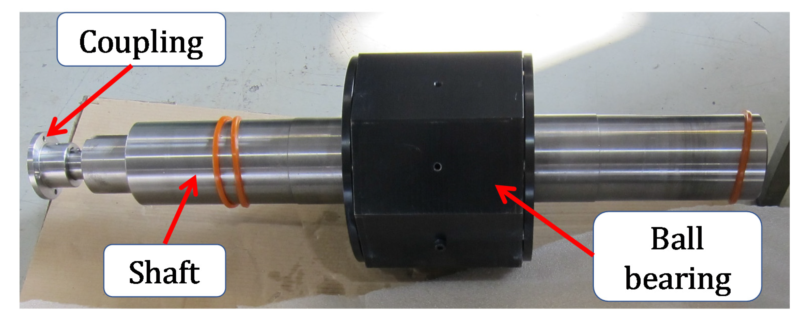
In this test rig, two hydraulic actuators are perpendicular to each other and form an angle of 45° in an arrangement with two load cells. These actuators can apply a maximum static load of 25 kN in the middle of the shaft by means of rolling bearings (see Figure 6). Thanks to this configuration of the test rig, the direction of the static load, as well as dynamic load, can be arranged at an arbitrary angle.
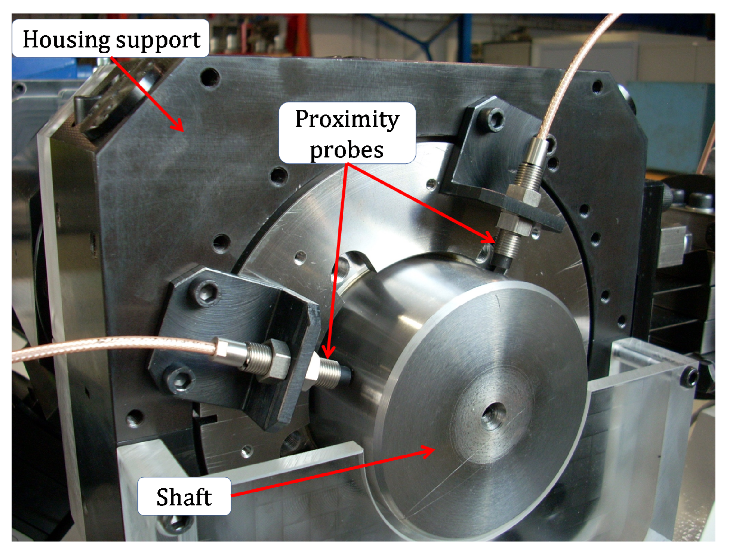
Two orthogonal proximity probes are set up on each bearing support (see in Figure 7) to measure the relative displacements between the shaft and the housing. The oil inlet temperature is also controlled by a PID temperature controller during the tests.
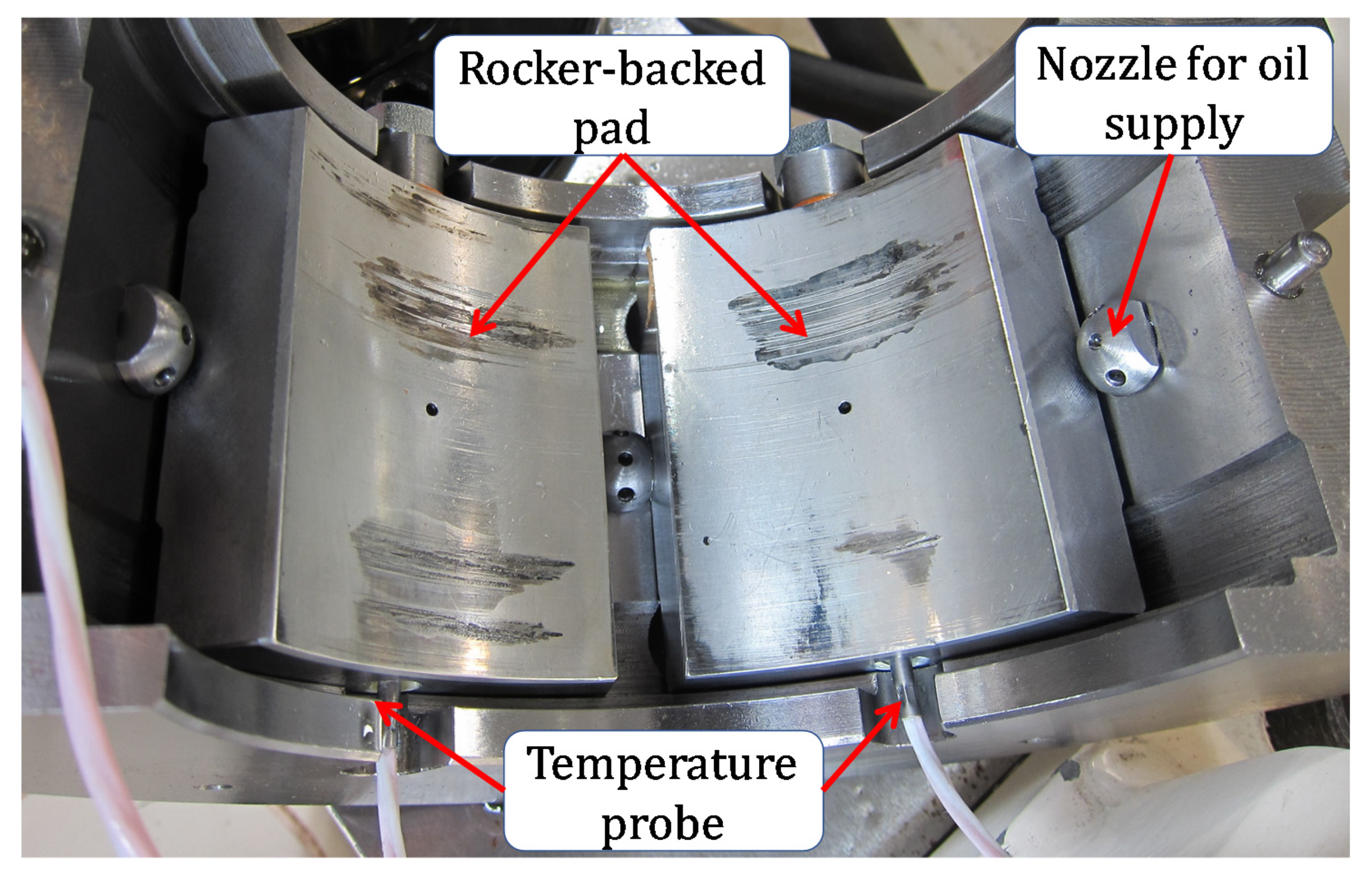
One temperature probe and one pressure probe are installed on each pad, as seen in Figure 8. The pressure amplitude in the middle of the pad is measured by a pressure probe through a small hole in the pad surface. The model and sensitivity of the instrumented sensors are provided in Table 5.
All signals from sensors installed in the test rig are acquired by means of a signal processing system (Figure 9). The voltage for all sensors is 24VDC. It consists of a power supply, transducer signal conditioning and a PCI DAQ chassis (NI cDAQ-9178).
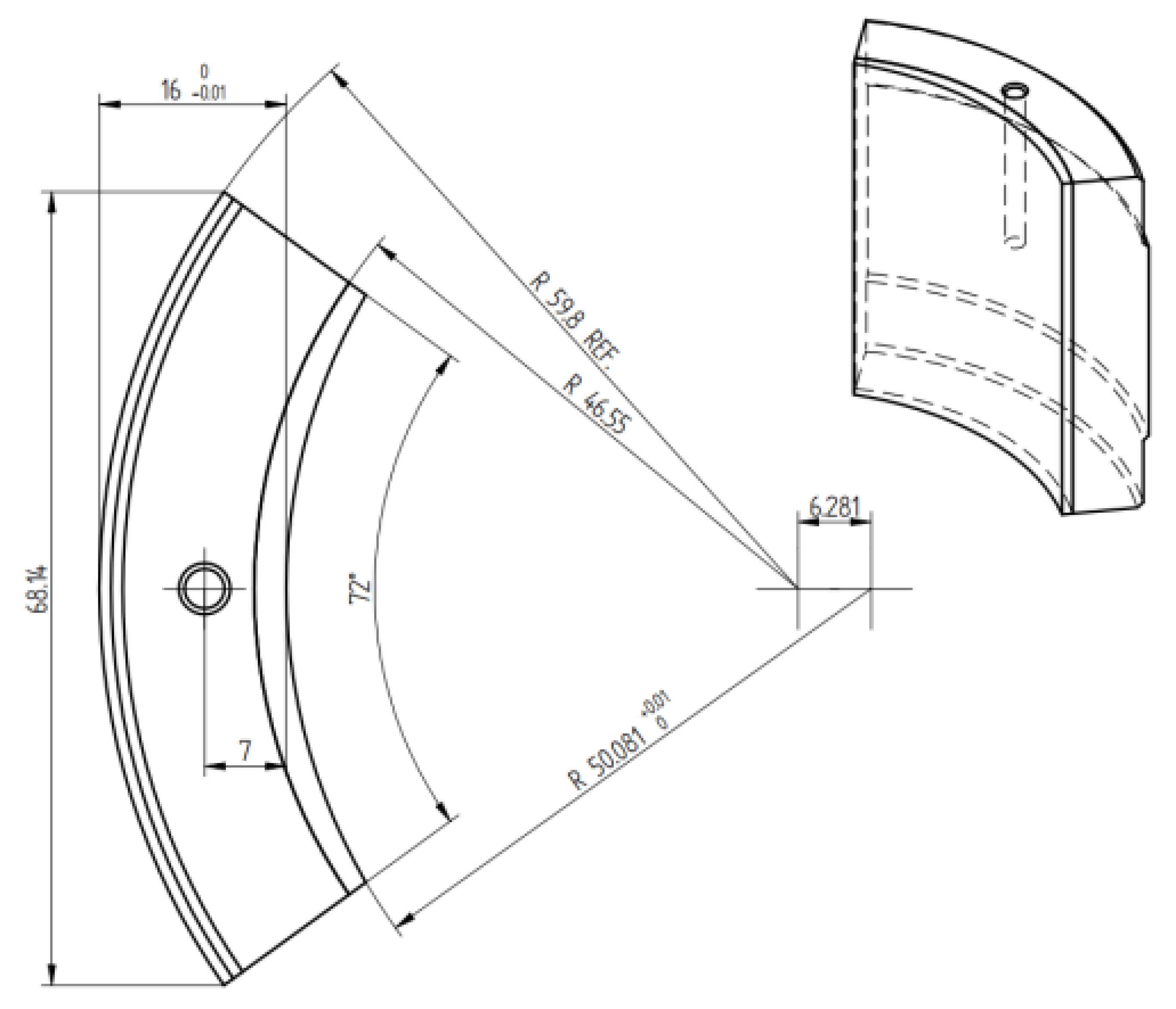
The pad includes the steel part of the pad base and the 3 mm thick Babbitt layer on the pad surface. A sketch of one single pad is shown in Figure 10.
All the bearing geometric characteristics and the operating conditions are listed in Table 6.
4. Results and Discussion
4.1. Clearance Profile
For a TPJB, the clearance profile has a polygon shape with np sides with respect to the number of pads installed in the bearing.
In order to obtain the clearance profile of TPJBs, a rotating force is applied on the non-rotating shaft through the deep groove precision ball bearings, so the rotor is slowly moved inside of the bearing housing. It should be noted that during the tests, the amplitude of rotating force is high enough to ensure that the shaft contacts all five pads. Please note that, during the test, oil is still supplied in order to avoid metal to metal contact. However, this force is just large enough to prevent considerable pivot deflections during the tests. This force can be generated thanks to the configuration of the test rig in which each hydraulic actuator generates a sinusoidal force and the phases of two these force signals are shifted by 270°.
Figure 11 shows the measured pentagonal clearance profiles (colored solid line) at different pad temperatures (from cold bearing at 25 °C to hot bearing at 55 °C) and the predicted nominal (black dash–dot line) of the TPJB. The temperature shown in Figure 11 is the average temperature of each pad surface acquired during the measurement. The cold-bearing clearances were plotted when the system had not worked for several hours. Hot clearances were recorded immediately (about 10 s) after performing several tests for a given rotational speed and load. Positions of the pad surface temperature sensor are already described (see Figure 8). In this test rig, pad #1 is the loaded pad, whereas pad #3 and pad #4 are the unloaded ones.
It is noticeable that the measured clearance shape of the actual bearing presents an asymmetrical pentagonal shape and is quite different from that of the nominal one, which shows a symmetrical pentagonal profile. This strange bearing profile of the test bearing has been described and explained in [28,29]. It is evident that as the temperature of inlet oil increases, the pentagonal shape tends to shrink. Since the bearing becomes hotter, the shaft, pads and bearing expand. Supposing the bearing bore remains stable, a hotter pad will get bigger, leading to a reduced profile. This trend shows a good agreement with the clearance profile changes reported in [21].
It can be detected that the clearance profiles of the test bearing of pad #4 show an unusual shape compared to those of the other pads. This consequence is probably due to the small thickness of pad #4 (15.981 mm), so at the location of pad #4, the movement of the shaft is be larger.
4.2. Eccentricity Measurement
It difficult to define the actual center of the bearing because of the thermal expansion of the bearing housing in which the proximity probes are installed. Therefore, steady-state shaft eccentricities should be recorded with respect to a lightly loaded equilibrium position, which corresponds to a shaft rotation of 3000 rpm and an applied static load equal to about 350 N on each bearing. The Sommerfeld number for this light load, corresponding to an eccentricity ratio of less than 0.01, is larger than 12 [34]. This position can be considered as the bearing center.
The values of eccentricity and the eccentricity ratio can be calculated as:
where (xequilibrium, yequilibrium) is the equilibrium position of the journal center and Cb is the bearing clearance.
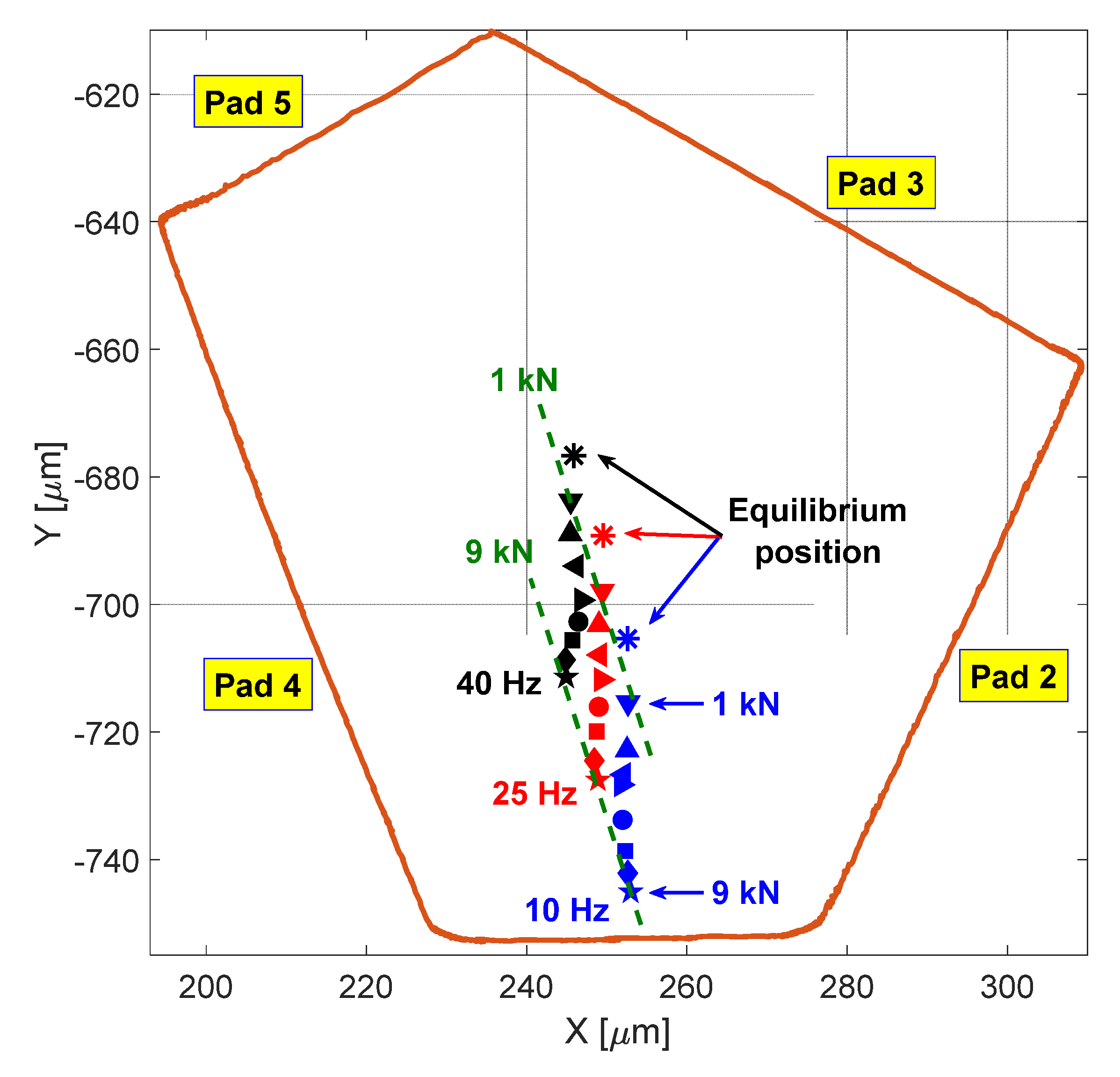
Three test series were run at a constant rotational frequency at, respectively, 10 Hz, 25 Hz and 40 Hz, with measurements taken using nine applied static loads, from 1 to 9 kN, in steps of 1 kN.
As shown in Figure 12, it is clear that when the rotational speed increases, the equilibrium and shaft position move up. When the speed is low, the measured eccentricity deviates slightly from the bearing vertical centerline. The largest eccentricity, which corresponds to the maximum load of 9 kN, is about 70 µm. When the rotational speed becomes higher, the deviation of the measured eccentricity from the vertical centerline grows (especially at 40 Hz), though the largest eccentricities decrease with respect to that of the test at 10 Hz.
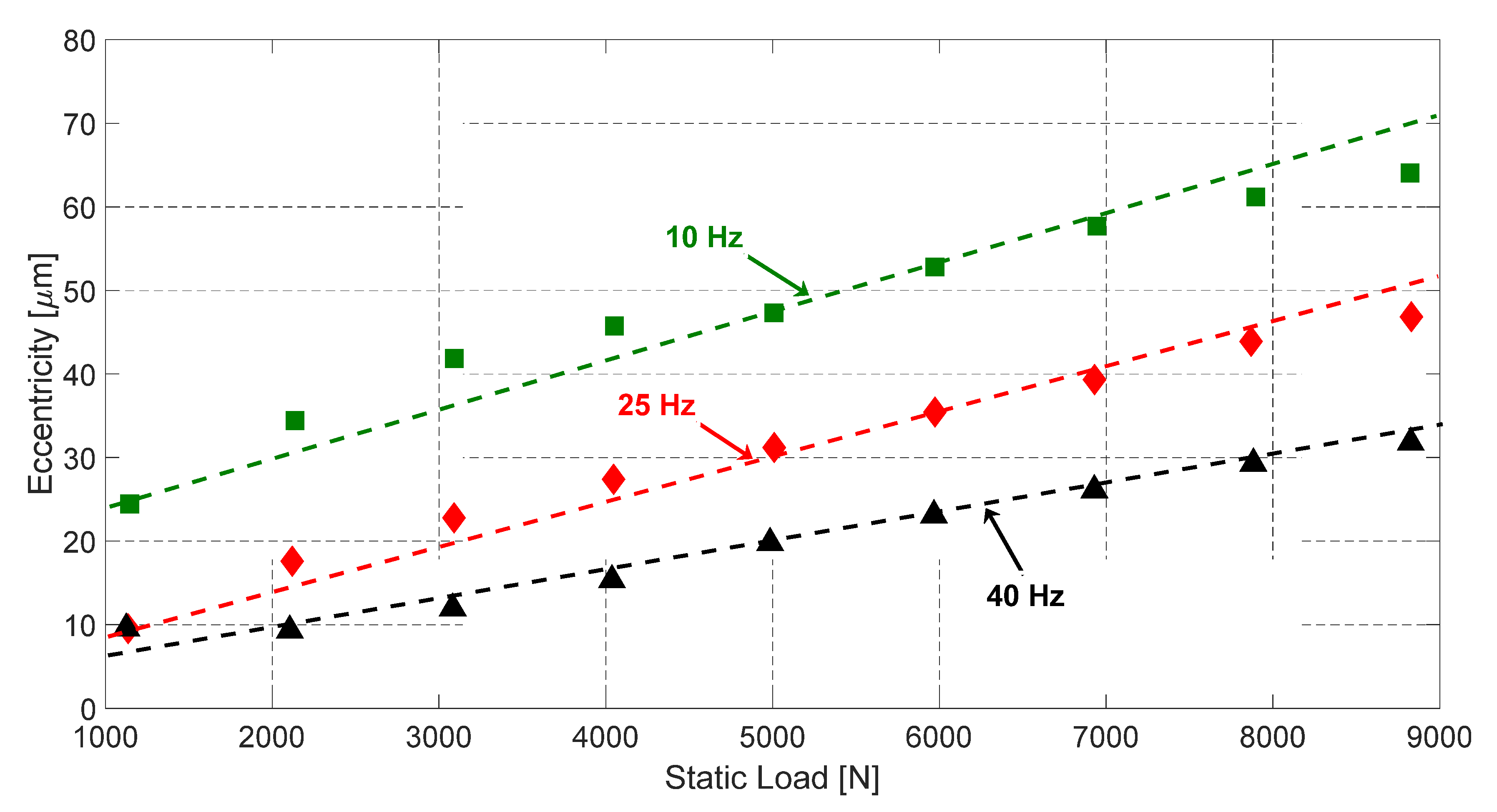
The measured eccentricities, as a function of the applied static loads, are shown in Figure 13 for three different rotational speeds. The eccentricity is almost inversely proportional to the rotational speed and practically linear to the static load.
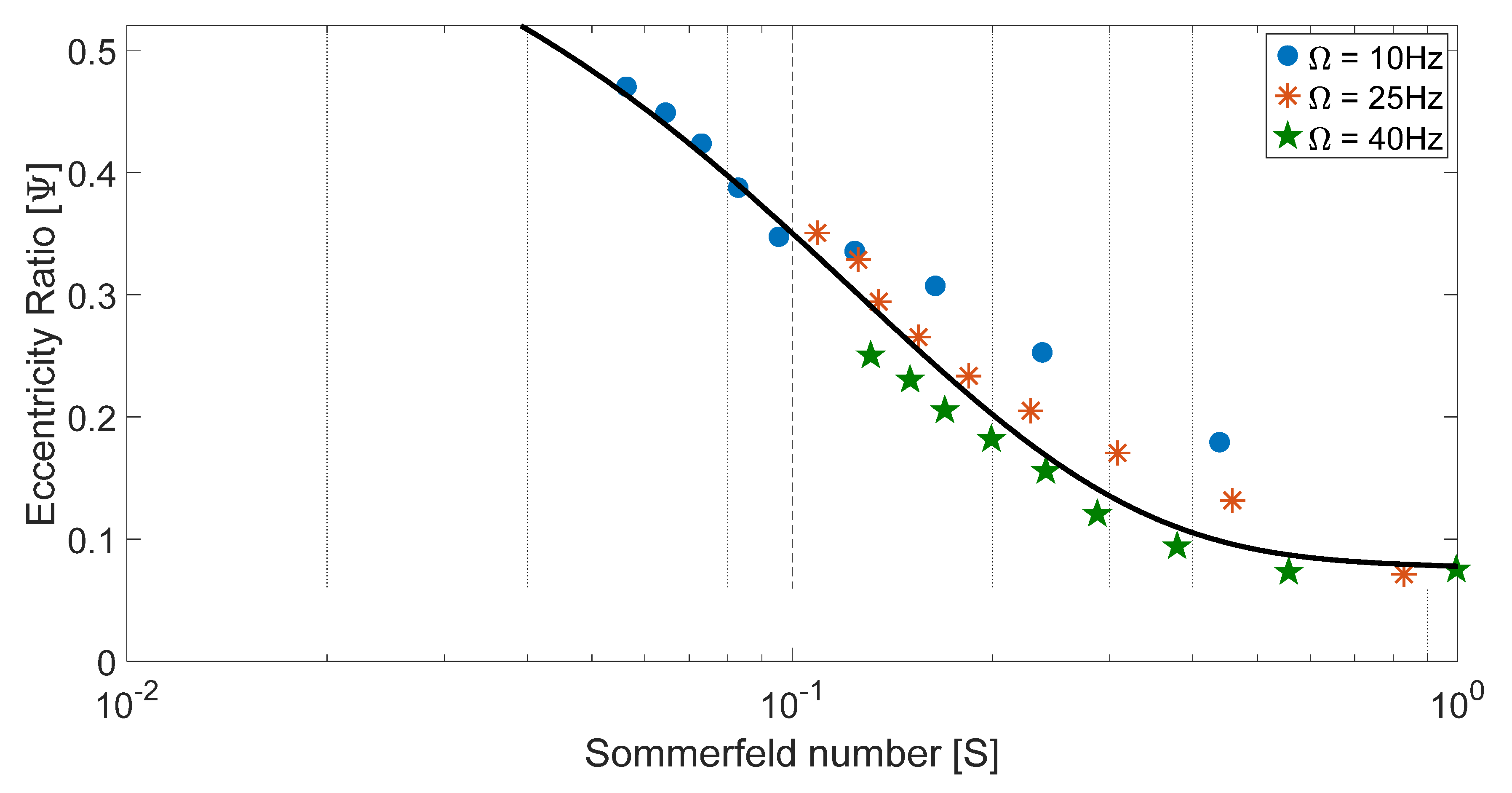
The measured eccentricity ratios of three test series as a function of the Sommerfeld number calculated using nominal radial clearance and pad average temperature are shown in Figure 14. These Sommerfeld numbers are based on the oil viscosity corresponding to the bearing pad temperature.
On the one hand, large Sommerfeld numbers (low applied load, high speed or high lubricant viscosity) determine low journal eccentricities, small eccentricity ratios or nearly centered operation, i.e., . It means that the applied load is nearly perpendicular to the journal eccentricity vector.
On the contrary, small Sommerfeld numbers (large applied load, low speed or low lubricant viscosity) determine large journal eccentricities or large eccentricity ratios, i.e., . It means that the vector of journal eccentricity has a similar direction to the applied load direction.
It is clearly seen that, in Figure 14, most of experimental results either touch or coincide with each other when the Sommerfeld number ranges from 0.1 to 0.5.
4.3. Temperature Distribution
As mentioned above, each pad of the tested bearing is instrumented with a temperature sensor located below the bearing’s surface to measure the pad temperature in the middle of the pad.
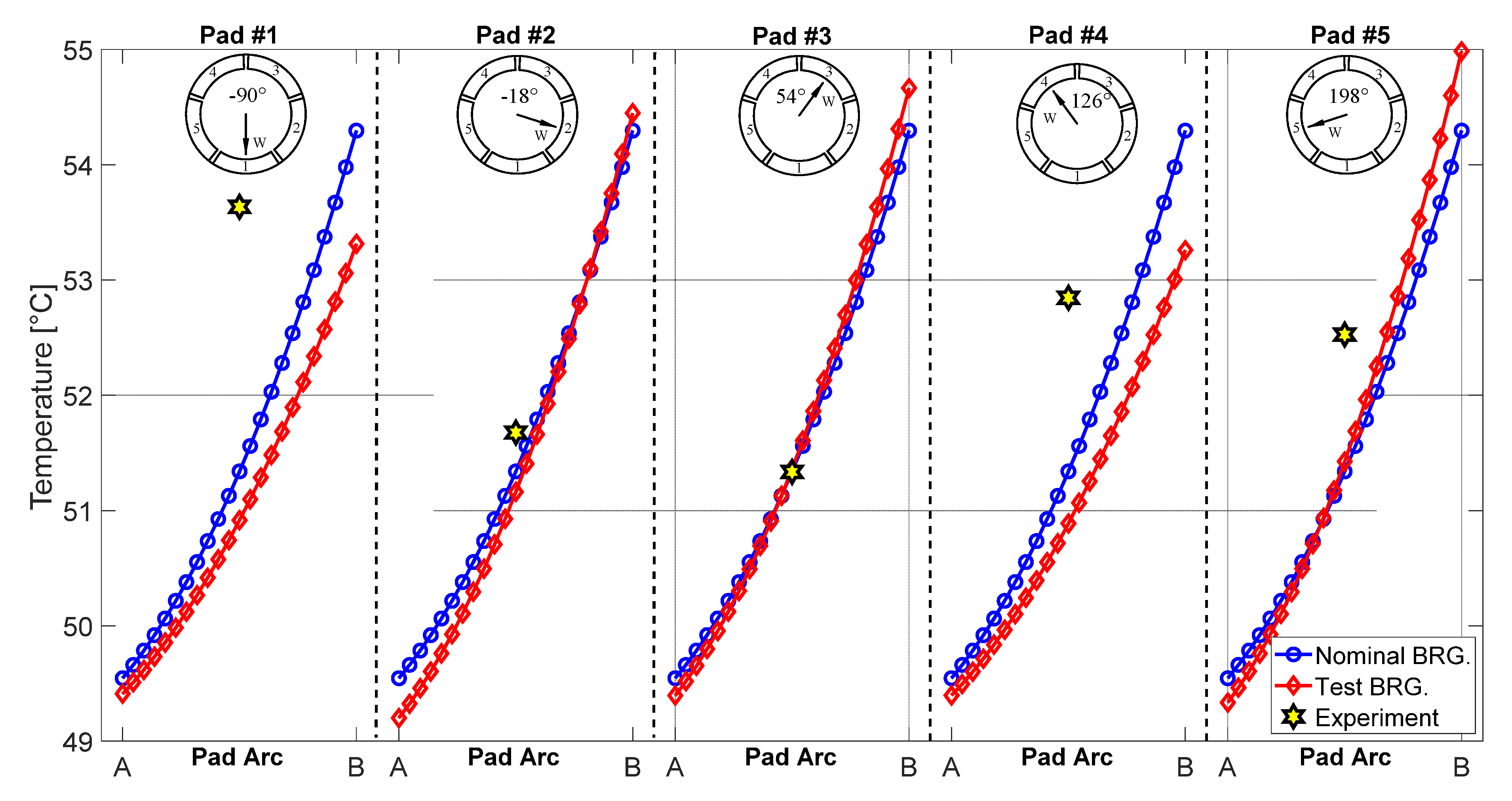
Figure 15 shows the predicted oil film temperatures on the middle plane of the axial length of the loaded pad from the leading edge (A) to the trailing edge (B) in the case of a LOP configuration of five pads. The measured pad subsurface temperature is also plotted for the corresponding positions. Please note that the temperature of the oil film along the radial direction is supposed to be constant. The temperature of the oil film given by the 2D model is applied on the active surfaces of the 3D model of the pad, where convective heat exchange with oil at 40 °C is assumed for all the other faces of the pads.
For ease of visualization, only the temperature distribution in the loaded pad is shown in Figure 15. It is possible to see that the pad temperature grows circumferentially on the middle plane from the leading edge to the trailing edge, about 4 °C for pads #1 and #4, and more or less 6 °C for the other three pads. For the nominal bearing, the predicted oil film temperature lines are identical for all pads because of the equal sizes of the pads. The difference between the nominal and the test bearings is negligible starting from the leading edge and is then quite evident at the trailing edge of the pads, about 1 °C.
Interestingly, while there is a difference between the measured metal temperature and the predicted film temperature in pads #1, #4 and #5 (about 1−2 °C), the values of the other two pads are nearly equal. For example, the measured temperature of pad #3 is 51.33 °C, whereas the prediction gives 51.36 °C for the test bearing.
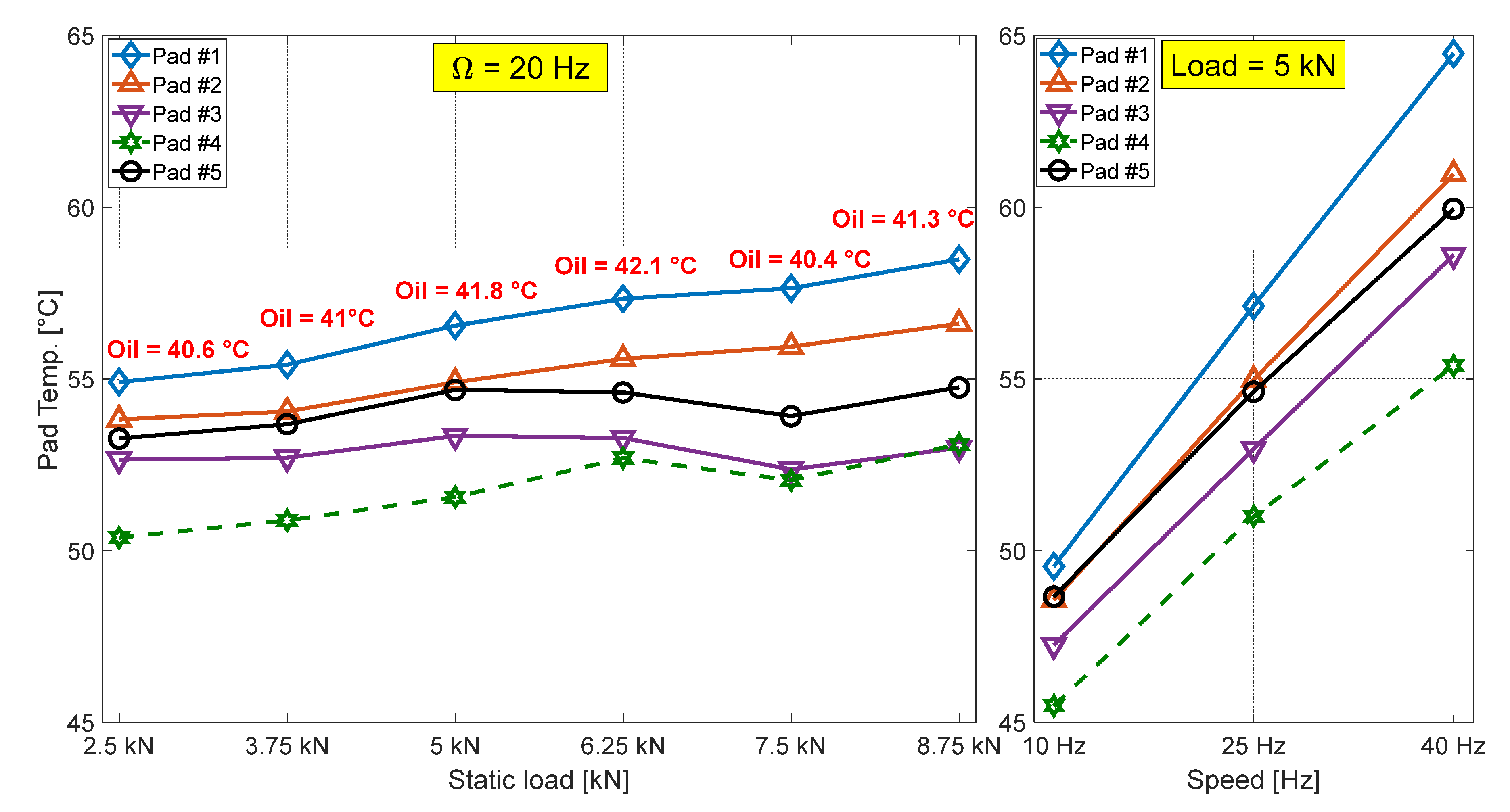
Figure 16 shows the measured temperature of each pad in the test bearing as a function of applied static load with a speed of 20 Hz and as a function of rotational speed with an applied static load of 5 kN. The static load in both cases was applied in the vertical direction, i.e., pad #1 was the loaded pad. During the test, the oil inlet temperature of each test was also recorded. Note that, because the shaft was run in the anticlockwise direction, pad #2 was loaded more than pad #5 (see Figure 2). The other two upper pads were unloaded pads.
It can be observed that the temperature of two loaded pads increases with an increase in the applied static load, ranging from 2.5 kN to 8.75 kN, in which the temperature of pad #1 was always higher than that of pad #2 by about 1–1.5 °C. The results show that there is a reduction in the temperature of pads #3, #4 and #5 in the test of 7.5 kN before an increase in the next test. This behavior can be easily explained thanks to the oil inlet temperature. In the test of 6.25 kN, the temperature of the oil supply was 42.1 °C, at which temperature the cooling system was activated. The decreasing oil temperature led to the reduction of these three pads’ temperatures.
It is possible to conclude that the pad temperature strongly depends on the shaft speed. This value increases by about 10–15 °C when the shaft speed increases by 30 Hz. These behaviors show an agreement with data published in [10,17].
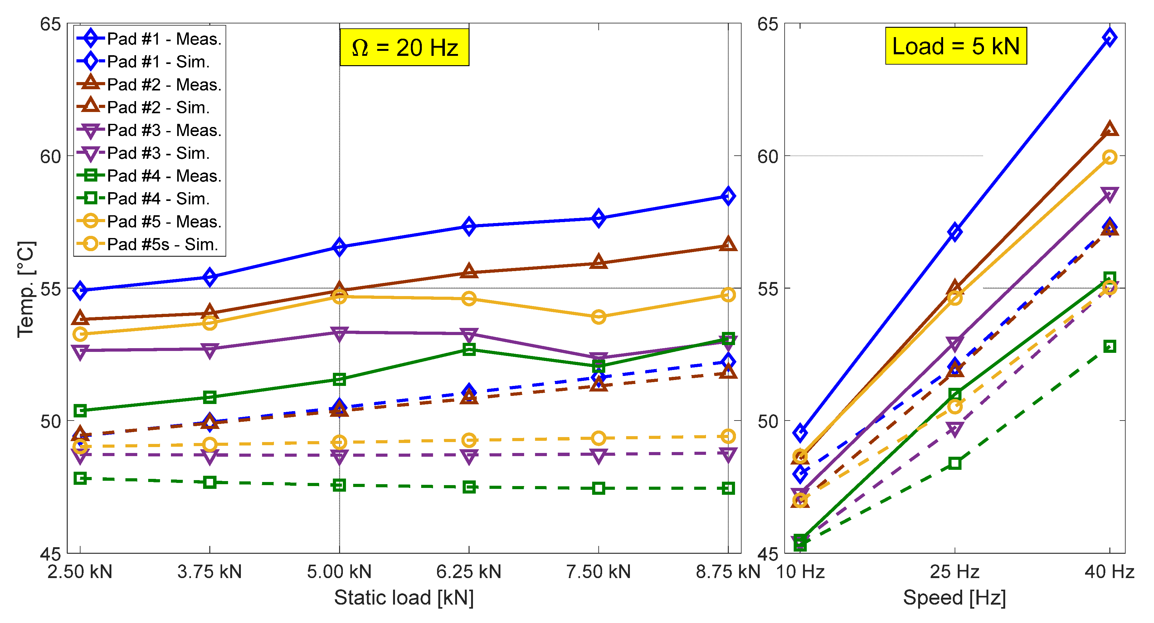
The comparison between the predicted and measured pad temperature as a function of static load and rotational speed is shown in Figure 17. The measured lines are plotted with solid lines, while a dash–dot line is used for the predicted ones.
It is possible to see that the simulation estimates the oil film temperature on the pad surface to be about 4 °C lower than the measured temperature. However, the code correctly estimates the variation trend of oil film temperature in the considered range. For example, while the oil film temperature of pads #1 and #2 increases linearly by about 3 °C when the applied static load increases from 2.5 kN to 8.75 kN, the other three pads show a fluctuation of temperature at the pad surface.
In the case of a variation of shaft speed with a given static load, the model underestimates the film temperature when the pad is unloaded or rotational speed is high. For instance, at 40 Hz, the measured temperature of pad #1 is higher by about 7 °C than that of the simulation. However, this value is about 2.4 °C for pad #4 at the same speed.
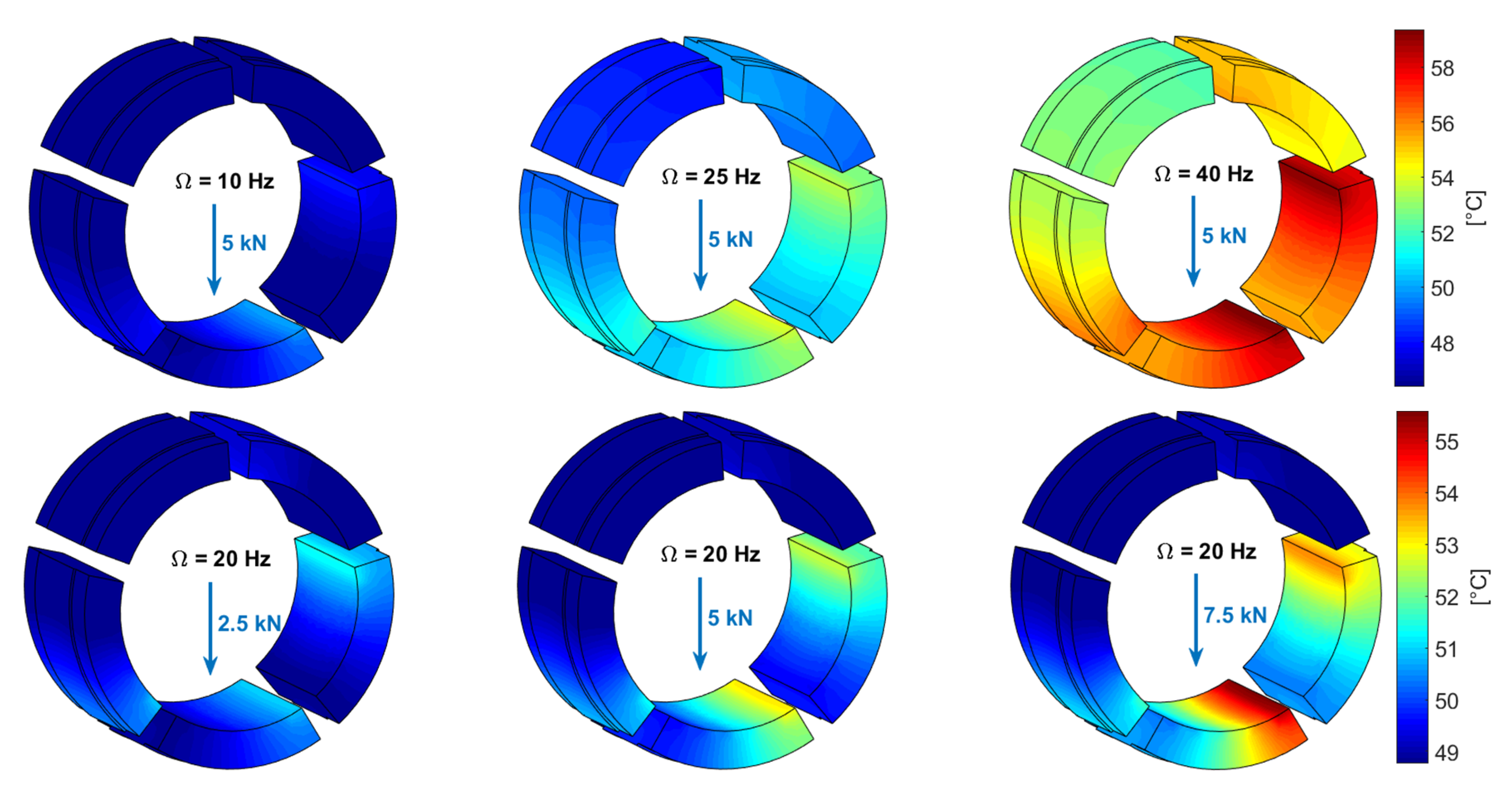
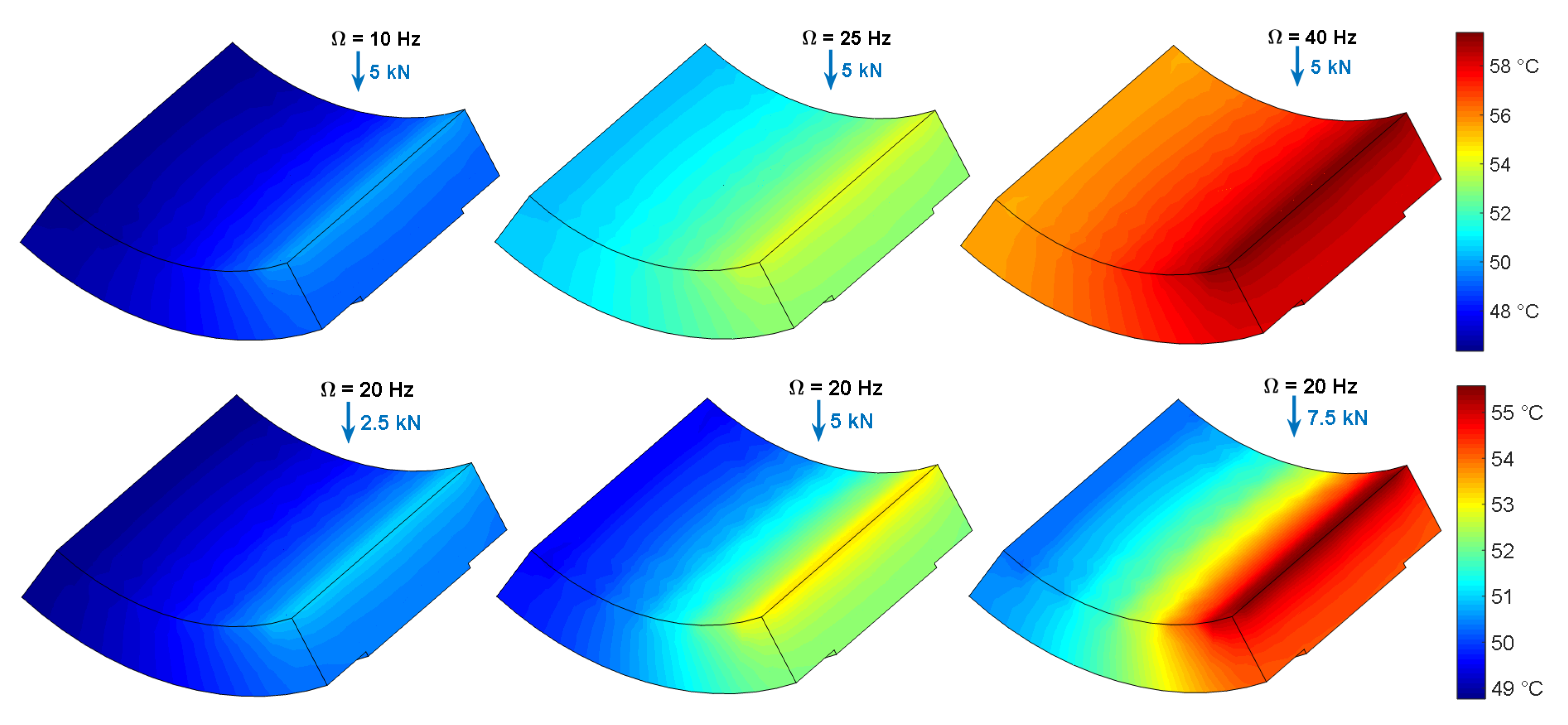
Figure 18 and Figure 19 show temperature distribution in all pads and only in pad #1 obtained by the 3D thermal model of the pads, respectively, in two cases: as a function of shaft speed with a given static load of 5 kN and as a function of applied static load with a constant speed of 25 Hz. It is possible to highlight a slight temperature gradient in the radial direction. The main temperature gradient is obtained in the circumferential direction. Note that the temperature distribution on the pad surface is also the predicted temperature distribution in the oil film along the circumferential direction.
In general, it can be observed that the maximum oil film temperature (the temperature of the pad surface) is reached on pad #1, which is the loaded pad. Due to the anticlockwise direction, the average temperature on pad #2, which is the pad after the loaded one (in the direction of tangential speed), is slightly lower than that of pad #1. Conversely, the minimum temperature is reached on pad #5, that is, the pad after the unloaded pads #3 and #4.
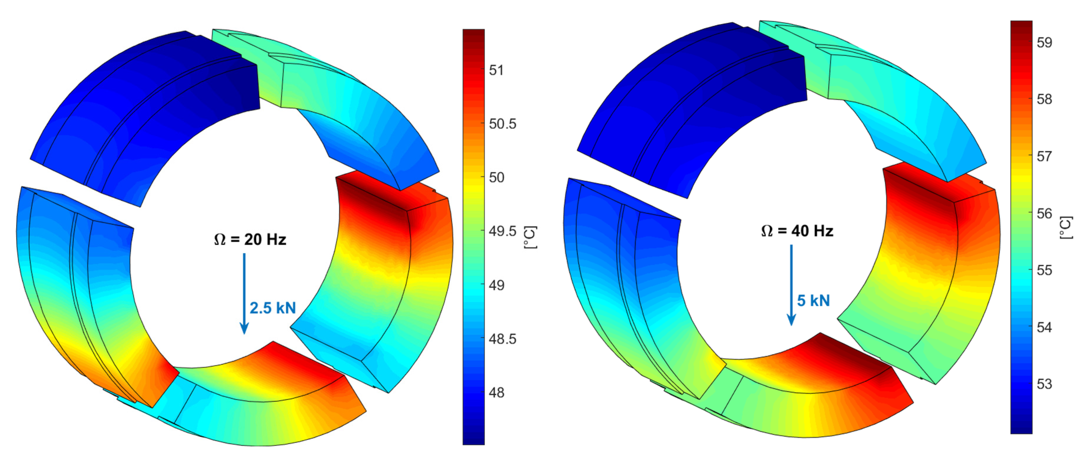
Interestingly, due to the asymmetric geometry, the predicted oil film temperature of the trailing edge of pad #2 is nearly equal to that of pad #1 or even higher in the case of a small static load, i.e., 2.5 kN. This effect can be easily explained due to the large thickness (16.015 mm), and pad #2 is still close to the rotating shaft although the shaft moves toward the middle of pad #1 (see Figure 20). For example, at a static load of 2.5 kN, the maximum oil film temperature of pad #2 is 51.4 °C, while this temperature is 50.9 °C for pad #1.
4.4. Pressure Distribution
The oil film pressure distribution is a very essential feature of TPJBs. The effect of the direction of the applied load on the pressure distribution results in a deviation in the performance of the TPJBs.
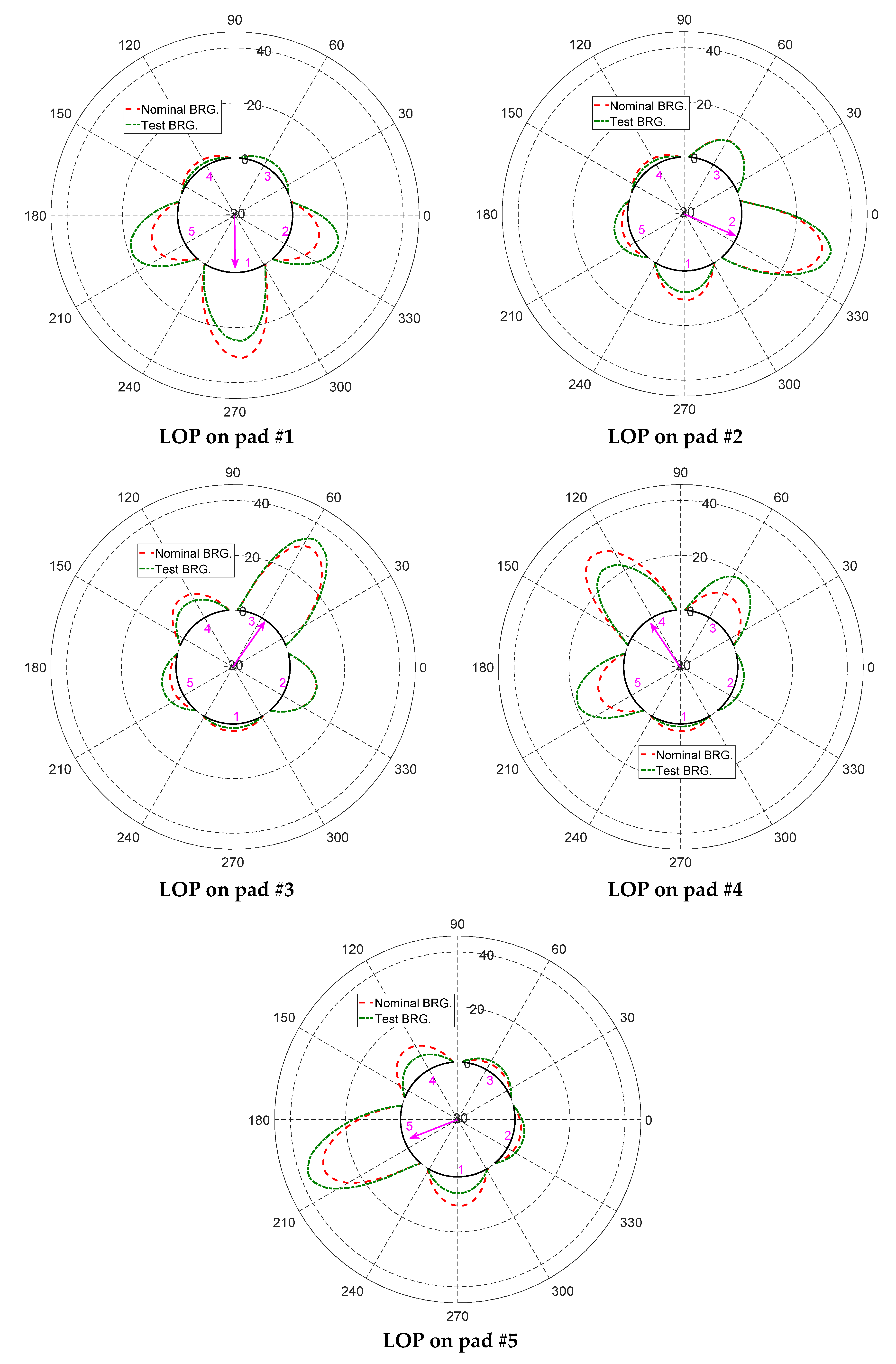
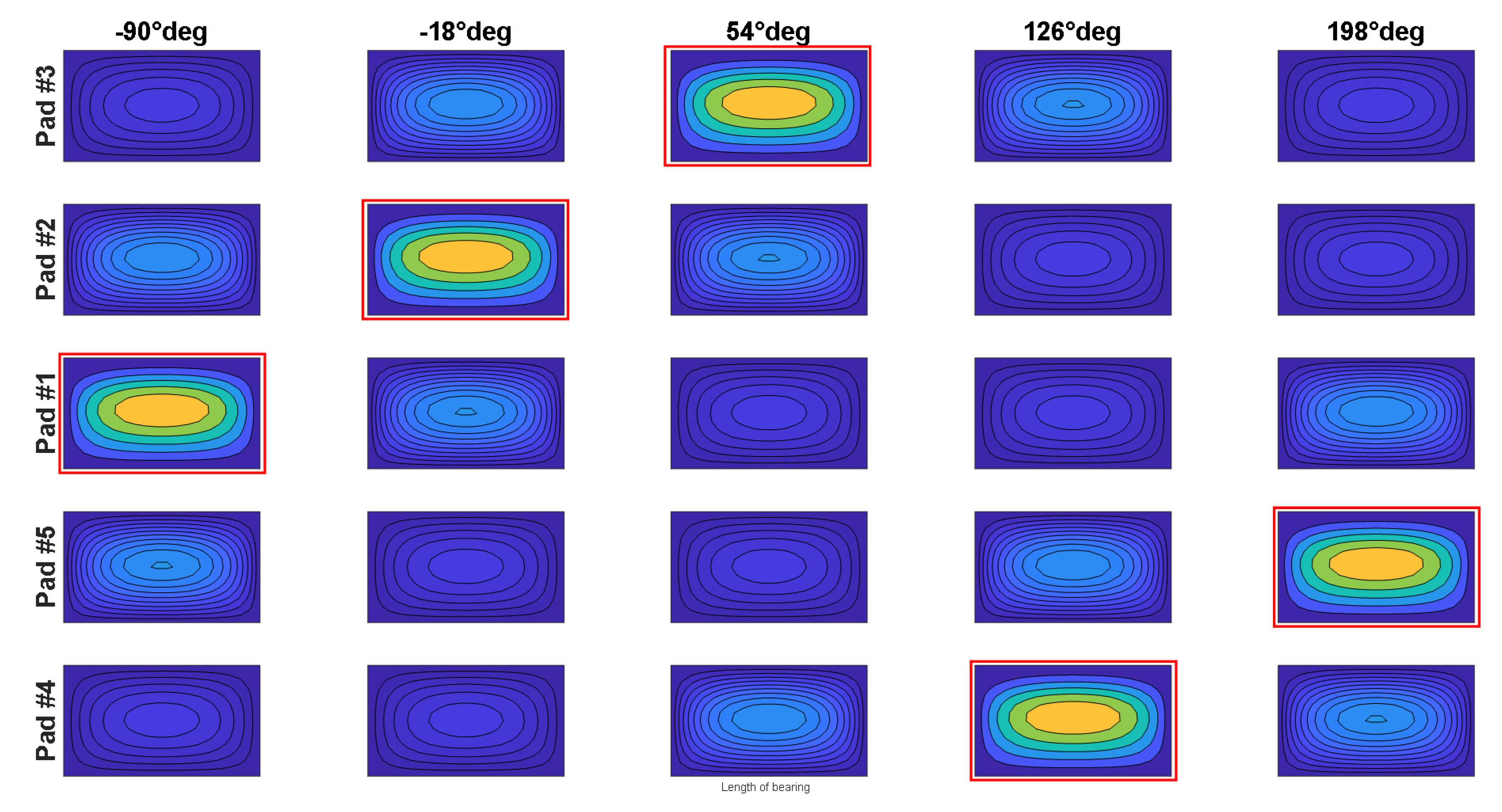
Figure 21 shows the simulated oil pressure distributions in the middle plane for test bearing and the nominal bearing as a function of load direction. For the sake of brevity, only LOP configuration on each pad was considered. In this simulation, the shaft was run at a speed of 20 Hz and the applied static load was 5 kN. Due to the identical geometry of the pads in the nominal bearing, a pressure with a maximum value of nearly 30 bar is distributed mostly on the loaded pads.
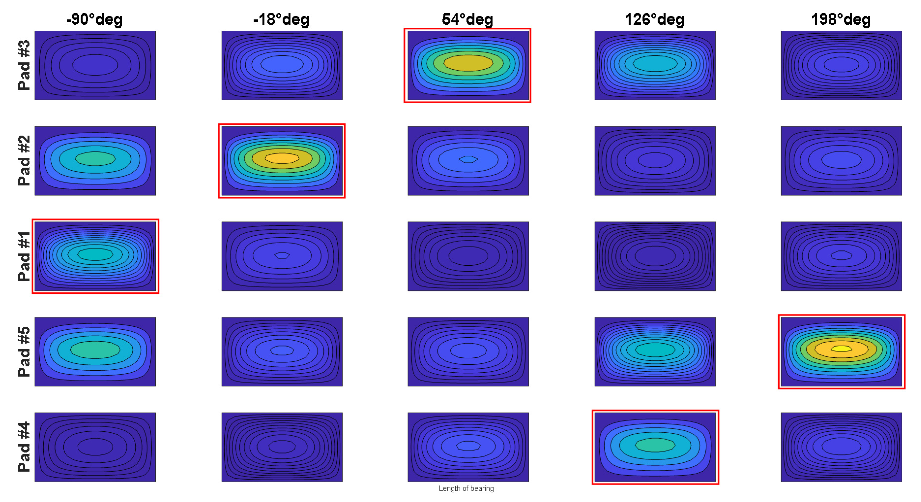
It should be noted that, for the test bearing, when pad #1 is loaded, its average pressure distribution is almost the same as that of pad #2 and pad #5. The same behavior also happens when the applied static load is at the center of pad #4. On the contrary, if the static load is applied in the middle of pad #2 (−18°), pad #3 (54°) or pad #5 (198°), the oil film pressure with a maximum pressure of nearly 38 bar distributes mainly across these three pads.
This phenomenon can be explained based on the pads’ thickness. Note that the thickness values of pad #1 (15.994 mm) and pad #4 (15.981 mm) are smaller than those of the nominal one (16 mm), whereas the other three pads show a contrary tendency. For example, if the direction of the applied static load is vertical, the shaft should move down to the center of pad #1. Nevertheless, due to the smaller thickness of pad #1, its average oil film thickness is still larger than that of the two consecutive pads (pads #2 and #5). In this case, the minimum thickness of the oil film of pad #1, pad #2 and pad #5 is about 37.6 µm, 32.5 µm and 31.2 µm, respectively. It makes the pressure distribution on pad #1 smaller than that of the two other pads. It also clear that, due to having the largest thickness value (16.018 mm), pad #5 will have a maximum pressure (nearly 38 bar in Figure 21) when pad #5 is loaded.
Figure 22 and Figure 23 show the contour plots of oil film pressure distribution on all pads in both real and nominal bearings as a function of load direction. For the sake of simplicity, only the LOP configuration of each pad is considered. The red rectangle on each contour indicates the loaded pad.
From these two plots, it is easily to observe the influence of the asymmetric geometry on oil pressure distribution.
5. Conclusions
This paper investigated the static characteristics of a five-pad rocker-backed TPJB with an asymmetric geometry. A TEHD model used for predictions takes into account the elasticity of the pads and pivots. This model uses the stiffness value of each pivot obtained from experiments. The bearing under test has a diameter of 100 mm and length of 70 mm. The bearing housing is manufactured to support the bearing under LBP and LOP arrangements. Some conclusions can be figured out from the results as follows:
- (1)
- The clearance profile of TPJBs has a polygon shape with the number of sides equal to the number of pads. The measured clearance profile of the test bearing is a strange pentagon, while the nominal one shows a regular pentagonal profile. As the bearing becomes hotter, the shaft, pads and bearing will expand, resulting in a reduction of the clearance profile.
- (2)
- It is more evident that when rotational speed increases, the equilibrium and shaft position will move up. When speed is low, the measured eccentricity deviates slightly from the bearing vertical centerline. The largest eccentricity corresponding to a maximum load of 9 kN and shaft speed of 10 Hz is about 70 µm.
- (3)
- The experiments show that the eccentricity is almost inversely proportional to the rotational speed. Additionally, most of the eccentricity ratios of all tests either touch or coincide with each other when the Sommerfeld number ranges from 0.1 to 0.5.
- (4)
- The measured data show that the pad temperature increases with an increase in the applied static load in which the temperature of pad #1 is always higher than that of pad #2, by nearly 1–1.5 °C. Additionally, it can be stated that the rotational speed has a considerable effect on the pad temperature.
- (5)
- As a function of load direction, on the one hand, the TEHD model underestimates the film temperature for pads #1, #4 and #5. On the other hand, the numerical results show a good agreement with measurement data for pad #2 and pad #3. The code predicts that the pad temperature grows circumferentially on the middle plane from the leading edge to the trailing edge, about 4 °C for pads #1 and #4, and more or less 6 °C for other three pads in the tested bearing.
- (6)
- The effect of the asymmetric geometry on the oil film pressure distribution is not negligible. Owing to the identical geometry of pads in the nominal bearing, the oil film pressure with a maximum value of nearly 30 bar is distributed mostly on the loaded pads.
Author Contributions
P.V.D. and S.C. performed the experiments. P.V.D. wrote the draft and revised the manuscript. S.C. developed the numerical simulation. S.C. and P.P. checked the logic described in the draft and the final version of the manuscript. All authors have read and agreed to the published version of the manuscript.
Funding
This research is funded by Funds for Science and Technology Development of the University of Danang under project number B2019-DN02-67.
Acknowledgments
The experiments were conducted at the Department of Mechanical Engineering, Politecnico di Milano, Italy.
Conflicts of Interest
The authors declare no conflict of interest.
References
- Hori, Y. Hydrodynamic Lubrication, 1st ed.; Springer: Tokyo, Japan, 2006. [Google Scholar]
- Tschoepe, D.P.; Childs, D. Measurements versus predictions for the static and dynamic characteristics of a four-pad, rocker-pivot, tilting-pad journal bearing. ASME J. Eng. Gas Turb. Power 2014, 136, 052501. [Google Scholar] [CrossRef] [Green Version]
- Ciulli, E.; Forte, P.; Libraschi, M.; Naldi, L.; Nuti, M. Characterization of high-power turbomachinery tilting pad journal bearings: First results obtained on a novel test bench. Lubricants 2018, 6, 4. [Google Scholar] [CrossRef] [Green Version]
- Croné, P.; Almqvist, A.; Larsson, R. Thermal turbulent flow in leading edge grooved and conventional tilting pad journal bearing segments-A comparative study. Lubricants 2018, 6, 97. [Google Scholar] [CrossRef] [Green Version]
- Hagemann, T.; Pfeiffer, P.; Schwarze, H. Measured and predicted operating characteristics of a tilting-pad journal bearing with jacking-oil device at hydrostatic, hybrid, and hydrodynamic operation. Lubricants 2018, 6, 81. [Google Scholar] [CrossRef] [Green Version]
- Wilkes, J.; Childs, D. Improving Tilting-Pad Journal Bearing Predictions: Part I: Model development and impact of rotor-excited versus bearing-excited impedance coefficients. ASME J. Eng. Gas Turb. Power 2013, 135, 012502. [Google Scholar] [CrossRef]
- Wilkes, J.; Childs, D. Improving tilting-pad journal bearing predictions—Part II: Comparison of measured and predicted rotor-pad transfer functions for a rocker-pivot tilting-pad journal bearing. ASME J. Eng. Gas Turb. Power 2013, 135, 012503. [Google Scholar] [CrossRef] [Green Version]
- Zhang, F.; Ouyang, W.; Hong, H.; Guan, Y.; Yuan, X.; Dong, G. Experimental study on pad temperature and film thickness of tilting-pad journal bearings with an elastic-pivot pad. Tribol. Int. 2015, 88, 228–235. [Google Scholar] [CrossRef]
- Zhiming, Z.; Ji, F.; Guan, Y.; Xu, J.; Yuan, X. Method and experiment of Temperature Collaborative Monitoring based on Characteristic Points for tilting pad bearings. Tribol. Int. 2017, 114, 77–83. [Google Scholar]
- Bang, K.; Kim, J.; Cho, Y. Comparison of power loss and pad temperature for leading edge groove tilting pad journal bearings and conventional tilting pad journal bearings. Tribol. Int. 2010, 43, 1287–1293. [Google Scholar] [CrossRef]
- Chatterton, S.; Pennacchi, P.; Vania, A.; Dang, P.V. Cooled Pads for Tilting-Pad Journal Bearings. Lubricants 2019, 7, 92. [Google Scholar] [CrossRef] [Green Version]
- Chatterton, S.; Pennacchi, P.; Vania, A.; Luca, A.; Dang, P.V. Tribo-design of lubricants for power loss reduction in the oil-film bearings of a process industry machine: Modelling and experimental tests. Tribol. Int. 2019, 130, 133–145. [Google Scholar] [CrossRef]
- Zulhanafi, P.; Syahrullail, S.; Ahmad, M.A. The Tribological Performance of Hydrodynamic Journal Bearing Using Bio-based Lubricant. Tribol. Ind. 2020, 42, 278–287. [Google Scholar] [CrossRef]
- Suryawanshi, S.R.; Pattiwar, J.T. Effect of TiO2 Nanoparticles Blended with Lubricating Oil on the Tribological Performance of the Journal Bearing. Tribol. Ind. 2018, 40, 370–391. [Google Scholar]
- Novotny, P. Mixed Lubrication Solution of Dynamically Loaded Radial Slide Bearings. Tribol. Ind. 2017, 39, 82–89. [Google Scholar] [CrossRef] [Green Version]
- Ochiai, M.; Sakai, F.; Hashimoto, H. Reproducibility of Gaseous Phase Area on Journal Bearing Utilizing Multi-Phase Flow CFD Analysis under Flooded and Starved Lubrication Conditions. Lubricants 2019, 7, 74. [Google Scholar] [CrossRef] [Green Version]
- Daniel, G.B.; Cavalca, K.L. Evaluation of the thermal effects in tilting pad bearing. Int. J. Rotating Mach. 2013, 7, 74. [Google Scholar] [CrossRef]
- Chatterton, S.; Dang, P.V.; Pennacchi, P.; Luca, A.; Flumian, F. Experimental evidence of a two-axial groove hydrodynamic journal bearing under severe operation conditions. Tribol. Int. 2017, 109, 416–427. [Google Scholar] [CrossRef]
- Wodtke, M.; Fillon, M.; Schubert, A.; Wasilczuk, M. Study of the Influence of Heat Convection Coefficient on Predicted Performance of a Large Tilting-Pad Thrust Bearing. ASME J. Tribol. 2013, 135, 021702. [Google Scholar] [CrossRef]
- Eling, R.; Te Wierik, M.; Van Ostayen, R.; Rixen, D. Towards Accurate Prediction of Unbalance Response, Oil Whirl and Oil Whip of Flexible Rotors Supported by Hydrodynamic Bearings. Lubricants 2016, 4, 33. [Google Scholar] [CrossRef] [Green Version]
- Wilkes, J.C.; Childs, D.W. Tilting Pad Journal Bearing—A Discussion on Stability Calculation, Frequency Dependence, and Pad and Pivot. ASME J. Eng. Gas Turb. Power 2012, 134, 122508. [Google Scholar] [CrossRef]
- Dimond, T.; Younan, A.; Allaire, P. A review of tilting pad bearing theory. Int. J. Rotating Mach. 2011, 2011, 1–23. [Google Scholar] [CrossRef] [Green Version]
- Kuznetsov, E.; Glavatskih, S. Dynamic characteristics of compliant journal bearings considering thermal effects. Tribol. Int. 2016, 94, 288–305. [Google Scholar] [CrossRef]
- Mehdi, S.M.; Jang, K.E.; Kim, T.H. Effects of pivot design on performance of tilting pad journal bearings. Tribol. Int. 2018, 119, 175–189. [Google Scholar] [CrossRef]
- Jin, Y.; Chen, F.; Zhang, F.; Yuan, X. Nonlinear dynamic performance of tilting-pad journal bearing with adjustable elastic pivot design. Tribol. Int. 2019, 136, 533–547. [Google Scholar]
- Sharmaa, N.; Kango, S. Influence of High Permeability Parameter on the Performance of Textured Porous Journal Bearings. Tribol. Ind. 2020. [Google Scholar] [CrossRef]
- Tauviqirrahmana, M.; Pratamaa, A.; Jamaria, M. Hydrodynamic Lubrication of Textured Journal Bearing Considering Slippage: Two-dimensional CFD Analysis Using Multiphase Cavitation Model. Tribol. Ind. 2019, 41, 401–415. [Google Scholar] [CrossRef]
- Dang, P.V.; Chatterton, S.; Pennacchi, P.; Vania, A. Effect of the load direction on non-nominal five-pad tilting-pad journal bearings. Tribol. Int. 2016, 98, 197–211. [Google Scholar] [CrossRef]
- Dang, P.V.; Chatterton, S.; Pennacchi, P. The Effect of the Pivot Stiffness on the Performances of Five-Pad Tilting Pad Bearings. Lubricants 2019, 7, 61. [Google Scholar] [CrossRef] [Green Version]
- Stachowiak, G.W.; Batchelor, A.W. Engineering Tribology, 4th ed.; Butterworth-Heinemann: Oxford, UK, 2014; pp. 223–246. [Google Scholar]
- Suh, J.; Palazzolo, A. Three-Dimensional Dynamic Model of TEHD Tilting-Pad Journal Bearing—Part I: Theoretical Modeling. ASME J. Tribol. 2015, 137, 041703. [Google Scholar] [CrossRef]
- Dang, P.V.; Chatterton, S.; Pennacchi, P.; Vania, A. Numerical investigation of the effect of manufacturing errors in pads on the behaviour of tilting-pad journal bearings. J. Eng. Tribol. 2018, 232, 480–500. [Google Scholar] [CrossRef]
- Pham, A.D.; Tran, T.L.; Ahn, H.J. Hysteresis curve analysis of a cycloid reducer using non-linear spring with a dead zone. Int. J. Precis. Eng. Manuf. 2017, 18, 375–380. [Google Scholar] [CrossRef]
- Nicolas, J.C.; Gunter, E.J.; Allaire, P.E. Stiffness and Damping Coefficients for the Five-Pad Tilting-Pad Bearing. ASLE Trans. 2008, 22, 113–124. [Google Scholar] [CrossRef]
Figure 1.
Schematic of a TPJB with one single pad.

Figure 2.
TPJB structure and oil supply plant.

Figure 3.
Boundary conditions of a single pad.

Figure 4.
Flowchart of the Matlab code.

Figure 5.
Photo of the test rig.

Figure 6.
Photo of shaft and rolling bearing.

Figure 7.
Proximity probes and pressure sensors installed on the bearing support.

Figure 8.
Photo of loaded pads with installed temperature probes.

Figure 9.
Signal processing system.

Figure 10.
Sketch and dimension of one pad in a TPJB.

Figure 11.
Measured clearance profiles at different pad temperatures and the predicted nominal clearance profile.
Figure 11.
Measured clearance profiles at different pad temperatures and the predicted nominal clearance profile.

Figure 12.
Measured shaft positions at different speeds vs. static load.

Figure 13.
Eccentricity measurements at different shaft speeds vs. static load.

Figure 14.
Bearing eccentricity ratio vs. Sommerfeld number for TPJBs.

Figure 15.
Predicted oil film temperatures along the center line of the loaded pad and measured pad temperatures. Positions A and B present the leading and trailing edge of the loaded pad, respectively.
Figure 15.
Predicted oil film temperatures along the center line of the loaded pad and measured pad temperatures. Positions A and B present the leading and trailing edge of the loaded pad, respectively.

Figure 16.
The measured temperature of each pad vs. static load (left) and rotational speed (right) in the test bearing.
Figure 16.
The measured temperature of each pad vs. static load (left) and rotational speed (right) in the test bearing.

Figure 17.
Measured and predicted temperature of pad #1 and pad #4 vs. static load (left) and rotational speed (right) in the test bearing.
Figure 17.
Measured and predicted temperature of pad #1 and pad #4 vs. static load (left) and rotational speed (right) in the test bearing.

Figure 18.
Predicted temperature distribution on all pads as a function of shaft speed (upper) and applied static load (lower) in the test bearing.
Figure 18.
Predicted temperature distribution on all pads as a function of shaft speed (upper) and applied static load (lower) in the test bearing.

Figure 19.
Predicted temperature distribution on pad #1 as a function of shaft speed (upper) and applied static load (lower) in the test bearing.
Figure 19.
Predicted temperature distribution on pad #1 as a function of shaft speed (upper) and applied static load (lower) in the test bearing.

Figure 20.
Average predicted temperature distribution of pad #2 is higher than (left) or nearly equal to (right) that of pad #1.
Figure 20.
Average predicted temperature distribution of pad #2 is higher than (left) or nearly equal to (right) that of pad #1.

Figure 21.
Predicted pressure distribution with LOP configuration on each pad of nominal bearing vs. tested bearing.
Figure 21.
Predicted pressure distribution with LOP configuration on each pad of nominal bearing vs. tested bearing.

Figure 22.
Predicted pressure distribution with LOP configuration of test bearing.

Figure 23.
Predicted pressure distribution with LOP configuration of nominal bearing.


Table 1.
Properties of ISO VG46 (at 40 °C).
| Item | Value |
|---|---|
| Viscosity [] | 0.03969 Pa.s |
| Density [] | 861 kg/m3 |
| Specific heat [cp] | 1.9766 kJ/(kg/°K) |
| Thermal expansion coefficient [] | 7.34 × 10⁻⁴ C−1 |
| Viscosity index [] | 96.552 |
| Thermal conductivity [kOIL] | 0.214 W/(m·K) |
Table 2.
Physical specifications of pad materials.
| Parameter | Babbitt | Steel | |
|---|---|---|---|
| Young’s modulus [GPa] | 40 | 206 | |
| Poisson’s ratio | 0.3 | 0.3 | |
| Thermal expansion coefficient [1/K] | 12 × 10−6 | 24 × 10−6 | |
| Heat conductivity [W/(m·K)] | 26 | 54 |
Table 3.
Boundary conditions used in the model of the pad.
| Face | Boundary Condition Type |
|---|---|
| Pad lateral and bottom surfaces | Convection with oil @ T supply (qoil = 50 W/(m2·K)) |
| Coating lateral surfaces (Babbitt layer) | Convection with oil @ T supply (qoil = 50 W/(m2·K)) |
| Fixed surface (F2) | Null displacement |
| Leading edge (F8) | Supplied temperature of 40 °C |
| Active surface | Given pressure and temperature distribution |
Table 4.
Pad thickness, bearing assembly clearance and preload factor of the bearing under test [30].
Table 4.
Pad thickness, bearing assembly clearance and preload factor of the bearing under test [30].
| Pad | Pad Thickness [mm] | Assembly Clearance [mm] | Preload Factor |
|---|---|---|---|
| Nominal | 16.000 | 0.070 | 0.44 |
| Pad #1 | 15.994 | 0.066 | 0.47 |
| Pad #2 | 16.015 | 0.045 | 0.64 |
| Pad #3 | 15.999 | 0.061 | 0.52 |
| Pad #4 | 15.981 | 0.078 | 0.37 |
| Pad #5 | 16.018 | 0.042 | 0.66 |
Table 5.
Model and sensitivity of the sensors.
| Sensor | Model/Type | Sensitivity |
|---|---|---|
| Proximity | CEMB T-NC/8-API | 7.78 mV/µm |
| Load cell | HBM U3 20kN | 2.0 mV/V |
| Temperature | Pt100 | 15 °C/V |
| Pressure | MEAS M513KPG41-00005-0 | 51.71 bar/V |
Table 6.
Rocker-backed TPJB specifications.
| Item | Value |
|---|---|
| Shaft diameter [mm] | 100 |
| Bearing length [mm] | 70 |
| Housing radius [mm] | 66 |
| Pad outer radius [mm] | 59.6 |
| Nominal assembled clearance [mm] | 0.070 |
| Nominal pad thickness [mm] | 16 |
| Angular amplitude of pads [°] | 60 |
| Lubricant oil | ISO-VG46 |
| Oil inlet temperature [°C] | 40 |
| Pad mass [kg] | 0.540 |
© 2020 by the authors. Licensee MDPI, Basel, Switzerland. This article is an open access article distributed under the terms and conditions of the Creative Commons Attribution (CC BY) license (http://creativecommons.org/licenses/by/4.0/).
Share and Cite
MDPI and ACS Style
Dang, P.V.; Chatterton, S.; Pennacchi, P. Static Characteristics of a Tilting Five-Pad Journal Bearing with an Asymmetric Geometry. Actuators 2020, 9, 89. https://0-doi-org.brum.beds.ac.uk/10.3390/act9030089
AMA Style
Dang PV, Chatterton S, Pennacchi P. Static Characteristics of a Tilting Five-Pad Journal Bearing with an Asymmetric Geometry. Actuators. 2020; 9(3):89. https://0-doi-org.brum.beds.ac.uk/10.3390/act9030089
Chicago/Turabian StyleDang, Phuoc Vinh, Steven Chatterton, and Paolo Pennacchi. 2020. "Static Characteristics of a Tilting Five-Pad Journal Bearing with an Asymmetric Geometry" Actuators 9, no. 3: 89. https://0-doi-org.brum.beds.ac.uk/10.3390/act9030089
Note that from the first issue of 2016, this journal uses article numbers instead of page numbers. See further details here.