Strengthening of Reinforced Concrete Slab-Column Connections with Carbon Fiber Reinforced Polymer Laminates

Department of Civil Engineering, National Chiao Tung University, Hsinchu 30010, Taiwan
*
Author to whom correspondence should be addressed.
Appl. Sci. 2020, 10(1), 265; https://0-doi-org.brum.beds.ac.uk/10.3390/app10010265
Submission received: 5 December 2019
/
Revised: 23 December 2019
/
Accepted: 26 December 2019
/
Published: 30 December 2019
(This article belongs to the Special Issue Structural Performances of Concrete Composite Members: Experimental, Theoretical, Numerical Approaches)
Abstract
:This study presents the structural behavior and punching shear strength of the concrete slab-column connections strengthened with carbon fiber reinforced polymer (CFRP) laminates. The variables considered for the twelve specimens included the compressive strength of the concrete, the ratio of the tensile steel reinforcement, and the amount of the CFRP laminates. Square concrete slabs were simply supported along four edges. During the test, monotonically concentrated load was applied to the stub column located at the center of the slab. The punching shear strength, stiffness, and mode of failure were investigated. Test results demonstrated that increasing the compressive strength of concrete, ratio of the steel reinforcement, and amount of the CFRP laminates led to an increase in the punching shear strength of the slabs. Moreover, the CFRP laminates were effective in appreciably increasing the punching shear strength of the slab-column connections. An analytical approach was conducted to calculate the punching shear strength of the slab-column connections strengthened with CFRP laminates. Based on the theory of reinforced concrete members, the application of the CFRP laminates increased the flexural strength of the slab and resulted in an increase of the effective depth of the slab section. Consequently, the punching shear strength was increased. The results of the analytical calculation revealed that the analytical work accurately predicted the experimental punching shear strength.
1. Introduction
The use of fiber reinforced polymer (FRP) to strengthen concrete structural members has greatly increased in recent decades [1,2]. Various advanced composite fabrics are utilized for this reinforcing technique instead of jacketing by the steel plate because the FRP possesses the features of high strength, lightweight, corrosion resistance, and easy handling. All of these advantages make fabric composites an attractive material for the application of repairing and strengthening the concrete members. Therefore, extensive research has been conducted to study the performance of concrete members strengthened with FRP composites. Research results have demonstrated that the FRP composites can considerably enhance the flexural and shear strength of reinforced concrete beams [3], as well as the ductility of reinforced concrete columns [4]. The FRP composites bonding technique has proven to be more cost-effective and easier in construction than other means.
Two-way reinforced concrete slabs in flat plate floor systems may fail in shear when the slabs are subjected to concentrated loads. Such punching shear failure occurs suddenly with almost no warning, involving a truncated cone around the column or the loaded area [5,6]. Generally, the load to cause punching shear failure of a flat slab is less than that for the flexural failure. Therefore, the punching shear strength should be increased to exclude the punching shear failure. Some experimental studies have been conducted to increase the load-carrying capacity of slabs by being strengthened with FRP composite. Chen and Li [7] tested reinforced concrete slab-column connections strengthened with glass fiber reinforced polymer (GFRP) laminates. Their test results demonstrated that GFRP effectively increased the punching shear capacity of the slab-column connections, especially for the slabs with low compressive strength of concrete and reinforcement ratio. They found that ACI code significantly underestimated the test results. Meisami et al. [8] tested two-way flat slabs strengthened by FRP fans where FRP fans were anchored at their ends like a fan. They observed that the strengthening could increase the shear capacity of the slab and might change the failure mode from shear to shear-flexural or flexural. Abdullah et al. [9] studied the application of non-prestressed and prestressed carbon fiber reinforced polymer (CFRP) plates on concrete column-slab connections. Four strips of CFRP plates were bonded on the tension surface of the slabs. They found that prestressed CFRP plates enhanced the serviceability such as the deflection and cracking. Esfahani et al. [10] used CFRP sheets to strengthen reinforced concrete slabs. Strips of CFRP sheets in two perpendicular directions were bonded to the bottom of the slabs. Their tests concluded that the use of CFRP sheets improved the punching shear strength of slabs.
Recently, studies of slab systems have been extended to the topics related to environmental impact and sustainability, such as the sensitivity analysis of the life cycle assessment [11] and the development of metamodels based on deep-learning methods [12].
This study presents the experimental and analytical investigations for the use of carbon FRP laminates to strengthen the slab-column connections. The effect of CFRP laminates bonded to the slabs is explored in terms of the mode of failure, load-deflection characteristics, punching shear strength, and stiffness.
2. Experimental Program
2.1. Test Specimens
Twelve specimens were constructed and tested to failure. The specimens were a 1000 mm square concrete slab of 100 mm thickness, with a stub column of 150 mm square cross section at the center of the slabs. The stub column was cast monolithically with the slab. Figure 1 shows the details of the test specimens. The design variables of the specimens were the compressive strength of concrete, ratio of tension steel reinforcement, and the amount of the CFRP laminates. Table 1 presents the specimens test matrix. The CSR1 and CSR2 symbols used for the specimen designation stand for the different amount of the tensile steel reinforcement. Concrete slabs were reinforced with Grade 60 deformed 10 mm diameter (No. 3) bars at an equal spacing of either 170 or 85 mm along both directions of the slab, resulting in 0.6% (CSR1 series) and 1.2% (CSR2 series) ratio of steel reinforcement, respectively. The C1 and C2 symbols represent the specified compressive strength of the concrete that was 14 and 28 MPa, respectively. The last symbol indicates the number of layers of the CFRP laminates.
2.2. Carbon Fiber Reinforced Polymer Laminates
FRP composite materials consist of high tensile strength fiber and matrix. The mechanical properties of FRP composite materials depend on the fiber volume content. Epoxy resin is generally used as the matrix. A major purpose of the lamination is to arrange the directional dependence of the strength and stiffness of the FRP composite material to match the loading environment of the structural element.
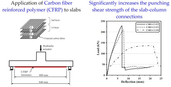
The carbon fiber has very high tensile strength compared to other fibers, such as glass fiber or aramid. The property of the raw material of carbon fiber used in the test has a tensile strength of 3920 MPa, certified by the supplier. The unidirectional carbon fabric weights 300 g/m2. A two-component epoxy matrix was used. Carbon fabric composite used in this study had a fiber volume content of 40%, which showed good processing ability in hand lay-up. Figure 2 shows the lamination of the CFRP laminates. A single layer of the laminate means that the unidirectional carbon fabric sheets were laminated once in both directions of the slab. The CFRP laminates were externally bonded on the tension side of the concrete slab, within a square of 800 mm in the central area of the slab. A column may exist on the tension side of the slab in practice. The laminates need to avoid the column zone. To effectively bond the CFRP laminates, the tension side of concrete surface was properly abraded to a rough surface before applying the primer. Carbon fabric sheets were then laminated to the surface using two-part epoxy after the primer was cured. To determine the tensile strength of the CFRP laminates, the CFRP laminates were tested according to ASTM D3039 test method [13]. The mechanical properties of the CFRP laminates are tabulated in Table 2.
2.3. Material Properties of the Concrete and Steel Bar
Material tests were carried out to determine the compressive strength of concrete and yield and tensile strengths of the steel reinforcing bar. While the specified compressive strengths of concrete designed for two series, C1 and C2, of the specimens were 14 and 28 MPa, the compressive strengths of concrete tested from the cylinders during the time of the test of the slabs resulted in average values of 18.2 and 27.6 MPa, respectively. The tensile strength test of the 10 mm dia. steel reinforcing bar showed that the yield and tensile strengths were 500 and 630 MPa, respectively. Figure 3 shows typical stress-strain curves of the CFRP laminates and steel bar used in this study.
2.4. Test Setup and Procedure
Figure 4 presents the test setup to simulate the slab-column subassembly. The concrete slab was pin-supported along the four edges, and the pin-to-pin distance was 840 mm. Monotonically concentrated load was applied to the stub column via the hydraulic actuator which was operated to apply incremental displacement in order to catch the post-failure behavior. The test was terminated when the load dropped significantly. To record the vertical deformation of the slab, deflection at center of the slab was measured using linear variable displacement transducers. The applied load was recorded through a load cell installed at the 500 kN actuator.
3. Test Results and Discussion
Table 3 summarizes the test results of ultimate strengths, deflection, failure mode, and initial stiffness. Specimens with various parameters behaved differently and their behaviors can be addressed regarding the failure mode, load-deflection relationship, ultimate strength, and stiffness characteristics which are discussed in the following sub-sections.
3.1. Behavior and Failure Mode
Two types of the behaviors were observed from the specimens. Therefore, failure of the specimens can be classified into two failure types: flexural failure and punching shear failure. Two specimens CSR1-C1-F0 and CSR1-C2-F0 (without laminates) developed flexural cracking on the tension side of the slab, along the diagonal direction of the slab and extended to the corners of the slab. These two specimens finally failed in flexure and showed a typical yield line failure mechanism on the tension side of the slab, as shown in Figure 5a.
Failure of the remaining specimens was clarified as the punching shear failure because the stub column suddenly punched through the slab at failure, accompanied by much smaller deflection of the slabs compared to that of the specimens failed in flexural. The load-carrying capacities dropped in a second when punching shear failure occurred. For those CFRP-strengthened specimens, there was no damage or debonding of the CFRP laminates at their ultimate loads, even though the laminates did not have a special anchor. After the slabs reached their ultimate loads, the CFRP laminates were gradually debonded starting from the vicinity of the crack surface when the stub column was pushed further. After the test, the laminates were peeled to examine the crack surface that was near a circle with approximate diameter of 360 to 600 mm, as shown in Figure 6. Typical cracking patterns of the slabs failed in punching are shown in Figure 5b,c. For the CFRP-strengthened specimens, there was no cracking within the truncated cone due to the strengthening of the laminates (Figure 5c), while the specimens CSR2-C1-F0 and CSR2-C2-F0 (without laminates) displayed more cracking within the truncated cone (Figure 5b).
Two specimens failed in a ductile manner by forming yield lines on the slab, while the remaining specimens exhibited a failure mode of punching. The formation of flexural or punching failure was addressed in the literature [14,15]. A lightly reinforced slab-column connection resulted in a ductile failure, but using a higher amount of the flexural reinforcement on the connection leads to a punching shear failure. In this test, the change of the failure mode from a ductile manner (specimens CSR1-C1-F0 and CSR1-C2-F0) to a brittle mode of punching shear failure (CFRP-strengthened specimens) was attributed primarily to the strengthening contributed from the CFRP laminates. The CFRP laminates functioned as an external tensile reinforcement and substantially increased the amount of the flexural reinforcement. Therefore, the strengthening of the CFRP laminates caused the change of the failure mode in the lightly reinforced slabs. Although the flexural failure mode of lightly reinforced specimens changed to a brittle punching shear failure when the specimens was strengthened with CFRP laminates, the punching shear failure could be excluded because the punching shear strength had been increased considerably. It is noted that, in various design codes, the strength reduction factor of the punching shear strength was much lower than that of the flexural strength.
3.2. Load-Deflection Characteristics
The curves of applied load-deflection of the specimens are shown in Figure 7. The deflections were measured at the center of the slab. The characteristics of load-deflection behavior can be used to distinguish the failure types. As shown in Figure 7a,b, the load-deflection curves of the specimens CSR1-C1-F0 and CSR1-C2-F0 indicated that they experienced flexural failure. Both specimens exhibited an initial stiffness of the uncracked slab at early loading stage, and followed by a decreasing stiffness when the tensile flexural crack developed. These two curves were characterized by the relatively large deflection with a horizontal plateau before the slabs developed their ultimate strengths. The deflections at ultimate strength of the specimens CSR1-C1-F0 and CSR1-C2-F0 were 15.99 and 20.93 mm (in Table 3), respectively, which were much greater than those of the specimens failed in punching shear. As shown in Table 3, the deflections at ultimate strength of the specimens failed in punching shear were certainly less than 10 mm.
The remaining specimens failed in punching shear, as revealed by the load-deflection curves. These specimens had similar behavior and their load-deflection curves were generally similar. Linear load-deflection relations were observed at the early loading stage, after which non-linear behavior with reduced stiffness was noticed. Moreover, these curves exhibited a very steep descending branch right after the ultimate load.
3.3. Ultimate Strength and Stiffness Characteristics
Ultimate strengths of the specimens are tabulated in Table 3. The strength increase percentages were calculated with respect to that of corresponding specimens without laminates. The ultimate strength increase percentages of the CFRP-strengthened specimens were significantly, ranging from 51.4 to 67.5% for CSR1 series of specimens, and from 16.9 to 40.9% for CSR2 series of specimens. It is clear that the CFRP laminates can considerably enhance the ultimate strength, especially for the lightly reinforced slabs. The comparison between C1 series of specimens and C2 series of specimens revealed the effect of the compressive strength of concrete on the punching shear strength. Increasing the compressive strength of concrete resulted in a higher punching shear strength. Similarly, the comparison between CSR1 series of specimens and CSR2 series specimens demonstrated that an increase in the steel reinforcement increased the punching shear strength. As shown in Table 3 and Figure 7, it is observed that the second layer of the CFRP laminates was marginally effective in enhancing the ultimate strength, especially for CSR1 series of specimens.
To evaluate the stiffness of the slab, an initial stiffness was defined in the form of secant stiffness. As observed from four specimens without laminates, slabs cracked at the load of approximately 20% of the ultimate strength. Therefore, the initial stiffness was determined by the secant passing the origin and the point corresponding to 20% of the ultimate strength. As shown in Table 3, the increase of the initial stiffness due to the laminates was considerably higher for CSR1-C1 series of specimens. The specimens without laminates had generally lower initial stiffness compared to the specimens with laminates. Nevertheless, the amount of the laminates did not noticeably change the initial stiffness.
4. Analytical Approach of Punching Shear Strength
In 1961, Moe [16] proposed that punching shear strength of a slab could be determined from its flexural strength. Moe suggested the punching shear strength, Vu, as
where is the compressive strength of concrete, in MPa; d is the effective depth of the slab section; c is the side length of a square column; is the perimeter of a square column; and is the shear strength corresponding to the flexural punching failure of the slab. The was calculated as
where b is the side dimension of a square slab; s is the side dimension between supports of a square slab; and is the flexural strength of the slab. The was derived based on the formation of a yield line mechanism of a slab at ultimate strength.
In order to take into account the contribution of the CFRP laminates, among the variables in Equations (1) and (2), the effective depth of the slab section, d, and the flexural strength, , needed to be amended to reflect the strengthening effect of the CFRP laminates [7]. To calculate the flexural strength of the slab strengthened with CFRP laminates, the fundamental theory to calculate the flexural strength of a reinforced concrete member was followed. Flexural strength was determined based on the deformation compatibility and force equilibrium. Figure 8 shows the strain, stress and force distributions in the slab section.
The calculation of the flexural strength of the slab strengthened with laminates are as follows:
- Linear strain distribution across the depth of the section was assumed, and the strains and stresses on the concrete, steel reinforcement, and CFRP laminates were determined accordingly.
- The flexural strength was achieved when extreme concrete compressive strain attained 0.003 or the CFRP laminates developed its ultimate strain.
- Consequently, the compressive force in the concrete, Cc, the tension force in the steel reinforcement Ts, and the tension force in the CFRP laminates, TCFRP, were able to be determined.
- Through the force equilibrium, the neutral axial depth, c, could be confirmed.
- Further, the flexural strength of the specimens strengthened with CFRP laminates was calculated as follows.where h is the thickness of the slab; and a is the depth of the rectangular concrete stress block.
Moreover, the flexural strength could be also determined as follows if an equivalent effective depth, deqv, was assumed.
Therefore, the equivalent effective depth was determined by the following equation.
Instead of d, substituting deqv to Equation (1), the punching shear strengths were calculated based on Moe’s equations. Table 4 summarizes the equivalent effective depth, and the ultimate strengths of the tests and analytical calculations. The increase of the effective depth owing to the contribution of the CFRP laminates on the flexural strength was observed. Moreover, increasing the amount of the CFRP laminates resulted in an increase in the equivalent effective depth. The calculated punching shear were in good agreement with the test results. The average ratios of the tested punching shear strength to analytical calculations was 1.01 and the coefficient of variation was 0.05.
5. Conclusions
Experimental and analytical studies on reinforced concrete slab-column connections strengthened with carbon fiber reinforced polymer (CFRP) laminates were presented. The test results demonstrated that the punching shear strength of concrete slab-column connections was considerably increased using externally bonded CFRP laminates. The enhancement was distinct for slabs with lower steel reinforcement ratio. Compared to the specimens without laminates, the increased percentages of the ultimate strength of the CFRP-strengthened specimens ranged from 51.4 to 67.5% for CSR1 series of specimens (0.6% steel reinforcement ratio) and from 16.9 to 40.9% for CSR2 series of specimens (1.2% steel reinforcement ratio). Analytical investigation was conducted to determine the punching shear strength of the CFRP-strengthened specimens. Flexural strength of the CFRP-strengthened specimens was first calculated based on the deformation compatibility and force equilibrium, and further, an equivalent effective depth was determined. Based on Moe’s equations, the punching shear strength was able to be calculated. Analytical work demonstrated that the average ratio of the tested to calculated punching shear strength was 1.01. The analytical approach can accurately predict the test results. Although the application of the CFRP laminates on the slab-column connection may change the flexural failure to punching shear failure, the punching shear strength of the slab strengthened with CFRP laminates has been increasing significantly and the punching shear failure can be prevented.
Author Contributions
Supervision, C.-C.C.; writing, C.-C.C.; investigation, S.-L.C. All authors have read and agreed to the published version of the manuscript.
Funding
This research was funded by the Ministry of Science and Technology, Taiwan.
Conflicts of Interest
The authors declare no conflict of interest.
References
- Van Den Einde, L.; Zhao, L.; Seible, F. Use of FRP composites in civil structural applications. Constr. Build. Mater. 2003, 17, 389–403. [Google Scholar] [CrossRef]
- Nanni, A. North American design guidelines for concrete reinforcement and strengthening using FRP: Principles, applications and unresolved issues. Constr. Build. Mater. 2003, 17, 439–446. [Google Scholar] [CrossRef]
- Norris, T.; Saadatmanesh, H.; Ehsani, M.R. Shear and flexural strengthening of R/C Beams with carbon fiber sheets. J. Struct. Eng. 1997, 123, 903–911. [Google Scholar] [CrossRef]
- Saadatmanesh, H.; Ehsani, M.R.; Li, M.W. Strength and ductility of concrete column externally reinforced with fiber composite straps. ACI Struct. J. 1994, 91, 434–447. [Google Scholar]
- Muttoni, A. Punching shear strength of reinforced concrete slabs without transverse reinforcement. ACI Struct. J. 2008, 105, 440–450. [Google Scholar]
- Micallef, K.; Sagaseta, J.; Fernández Ruiz, M.; Muttoni, A. Assessing punching shear failure in reinforced concrete flat slabs subjected to localised impact loading. Int. J. Impact Eng. 2014, 71, 17–33. [Google Scholar] [CrossRef] [Green Version]
- Chen, C.C.; Li, C.Y. Punching shear strength of reinforced concrete slabs strengthened with glass fiber-reinforced polymer laminates. ACI Struct. J. 2005, 102, 535–542. [Google Scholar]
- Meisami, M.H.; Mostofinejad, D.; Nakamura, H. Strengthening of flat slabs with FRP fan for punching shear. Compos. Struct. 2015, 119, 305–314. [Google Scholar] [CrossRef]
- Abdullah, A.; Bailey, C.G.; Wu, Z.J. Tests investigating the punching shear of a column-slab connection strengthened with non-prestressed or prestressed FRP plates. Constr. Build. Mater. 2013, 48, 1134–1144. [Google Scholar] [CrossRef]
- Esfahani, M.R.; Kianoush, M.R.; Moradi, A.R. Punching shear strength of interior slab-column connections strengthened with carbon fiber reinforced polymer sheets. Eng. Struct. 2009, 31, 1535–1542. [Google Scholar] [CrossRef]
- Ferreiro-Cabello, J.; Fraile-Garcia, E.; Martinez-Camara, E.; Perez-de-la-Parte, M. Sensitivity analysis of life cycle assessment to select reinforced concrete structures with one-way slabs. Eng. Struct. 2017, 132, 586–596. [Google Scholar] [CrossRef]
- Ferreiro-Cabello, J.; Fraile-Garcia, E.; Martinez de Pison Ascacibar, E.; Martinez-de-Pison, F.J. Metamodel-based design optimization of structural one-way slabs based on deep learning neural networks to reduce environmental impact. Eng. Struct. 2018, 155, 91–101. [Google Scholar] [CrossRef]
- ASTM D3039. Standard Test Method for Tensile Properties of Polymer Matrix Composite Materials; American Society for Testing and Materials: West Conshohocken, PA, USA, 2017. [Google Scholar]
- Alexander, S.D.B.; Simmonds, S.H. Bond model for concentric punching shear. ACI Struct. J. 1992, 89, 325–334. [Google Scholar]
- Menétrey, P. Relationships between flexural and punching failure. ACI Struct. J. 1998, 95, 412–419. [Google Scholar]
- Moe, J. Shearing strength of reinforced concrete slabs and footings under concentrated loads. Development Department Bulletin; Portland Cement Association: Skokie, IL, USA, 1961; No. D47. [Google Scholar]
Figure 1.
Test specimen.

Figure 2.
Lay-up arrangement of CFRP laminates.

Figure 3.
Stress-strain curves of CFRP laminate and steel bar.

Figure 4.
Test setup.

Figure 5.
Typical cracking patterns on the tension surface of the slab: (a) Flexural failure; (b) Punching shear failure of slabs without CFRP laminates; (c) Punching shear failure of slabs with CFRP laminates.
Figure 5.
Typical cracking patterns on the tension surface of the slab: (a) Flexural failure; (b) Punching shear failure of slabs without CFRP laminates; (c) Punching shear failure of slabs with CFRP laminates.

Figure 6.
Punching shear failure on the tension surface of the specimen CSR1-C2-F2 after peeled off the CFRP laminates.
Figure 6.
Punching shear failure on the tension surface of the specimen CSR1-C2-F2 after peeled off the CFRP laminates.

Figure 7.
Load-deflection curves: (a) CSR1-C1 series of specimens; (b) CSR1-C2 series of specimens; (c) CSR2-C1 series of specimens; (d) CSR2-C2 series of specimens.
Figure 7.
Load-deflection curves: (a) CSR1-C1 series of specimens; (b) CSR1-C2 series of specimens; (c) CSR2-C1 series of specimens; (d) CSR2-C2 series of specimens.

Figure 8.
Strain, stress and force distributions in the section at ultimate strength.


Table 1.
Specimens test matrix. CFRP: carbon fiber reinforced polymer.
| Specimen | Spacing of ϕ10 mm Steel Bar (mm) | Concrete Compressive Strength (MPa) | Number of Layers of CFRP Laminates |
|---|---|---|---|
| CSR1-C1-F0 | 170 | 18.2 | - |
| CSR1-C1-F1 | 170 | 18.2 | 1 |
| CSR1-C1-F2 | 170 | 18.2 | 2 |
| CSR1-C2-F0 | 170 | 27.6 | - |
| CSR1-C2-F1 | 170 | 27.6 | 1 |
| CSR1-C2-F2 | 170 | 27.6 | 2 |
| CSR2-C1-F0 | 85 | 18.2 | - |
| CSR2-C1-F1 | 85 | 18.2 | 1 |
| CSR2-C1-F2 | 85 | 18.2 | 2 |
| CSR2-C2-F0 | 85 | 27.6 | - |
| CSR2-C2-F1 | 85 | 27.6 | 1 |
| CSR2-C2-F2 | 85 | 27.6 | 2 |
Table 2.
Mechanical properties of the CFRP laminates.
| Layers of CFRP Laminates | Thickness (mm) | Ultimate Strength (MPa) | Ultimate Strain (mm/mm) | Modulus of Elasticity (MPa) |
|---|---|---|---|---|
| 1 | 0.62 | 587 | 0.0119 | 49,300 |
| 2 | 1.15 | 888 | 0.0147 | 60,400 |
Table 3.
Test results.
| Specimen | Ultimate Strength (kN) | Strength Increase * (%) | Deflection ** (mm) | Failure Mode | Initial Stiffness (kN/mm) |
|---|---|---|---|---|---|
| CSR1-C1-F0 | 113.7 | - | 15.99 | Flexural | 29.9 |
| CSR1-C1-F1 | 172.1 | 51.4 | 6.42 | Punching shear | 45.3 |
| CSR1-C1-F2 | 186.2 | 63.8 | 5.86 | Punching shear | 51.7 |
| CSR1-C2-F0 | 136.8 | - | 20.93 | Flexural | 43.4 |
| CSR1-C2-F1 | 209.1 | 52.9 | 7.66 | Punching shear | 49.8 |
| CSR1-C2-F2 | 229.1 | 67.5 | 6.96 | Punching shear | 49.3 |
| CSR2-C1-F0 | 145.9 | - | 7.52 | Punching shear | 37.1 |
| CSR2-C1-F1 | 170.6 | 16.9 | 6.32 | Punching shear | 38.9 |
| CSR2-C1-F2 | 196.8 | 34.9 | 6.48 | Punching shear | 39.0 |
| CSR2-C2-F0 | 176.1 | - | 9.11 | Punching shear | 40.3 |
| CSR2-C2-F1 | 225.0 | 27.8 | 7.54 | Punching shear | 51.1 |
| CSR2-C2-F2 | 248.2 | 40.9 | 6.57 | Punching shear | 51.2 |
* Compared to the control specimen (-F0, without CFRP laminates). ** Measured at the center of the slab when the specimen reached its ultimate strength.
Table 4.
Comparison between test results and analytical calculations.
| Specimen | Equivalent Effective Depth deqv | Test Result Vu,Test | Analytical Calculation Vu,Moe | Ratio of Vu,Test/Vu,Moe |
|---|---|---|---|---|
| CSR1-C1-F0 | 70.5 | 113.7 | 120.4 | 0.94 |
| CSR1-C1-F1 | 83.8 | 172.1 | 174.0 | 0.99 |
| CSR1-C1-F2 | 87.2 | 186.2 | 190.8 | 0.98 |
| CSR1-C2-F0 | 70.5 | 136.8 | 138.8 | 0.99 |
| CSR1-C2-F1 | 86.3 | 209.1 | 221.7 | 0.94 |
| CSR1-C2-F2 | 89.5 | 229.1 | 244.0 | 0.94 |
| CSR2-C1-F0 | 70.5 | 145.9 | 143.4 | 1.02 |
| CSR2-C1-F1 | 76.9 | 170.6 | 165.2 | 1.03 |
| CSR2-C1-F2 | 82.3 | 196.8 | 181.6 | 1.08 |
| CSR2-C2-F0 | 70.5 | 176.1 | 170.9 | 1.03 |
| CSR2-C2-F1 | 78.9 | 225.0 | 209.9 | 1.07 |
| CSR2-C2-F2 | 82.5 | 248.2 | 228.1 | 1.09 |
| Mean value | 1.01 | |||
| Coeff. of variation | 0.05 |
© 2019 by the authors. Licensee MDPI, Basel, Switzerland. This article is an open access article distributed under the terms and conditions of the Creative Commons Attribution (CC BY) license (http://creativecommons.org/licenses/by/4.0/).
Share and Cite
MDPI and ACS Style
Chen, C.-C.; Chen, S.-L. Strengthening of Reinforced Concrete Slab-Column Connections with Carbon Fiber Reinforced Polymer Laminates. Appl. Sci. 2020, 10, 265. https://0-doi-org.brum.beds.ac.uk/10.3390/app10010265
AMA Style
Chen C-C, Chen S-L. Strengthening of Reinforced Concrete Slab-Column Connections with Carbon Fiber Reinforced Polymer Laminates. Applied Sciences. 2020; 10(1):265. https://0-doi-org.brum.beds.ac.uk/10.3390/app10010265
Chicago/Turabian StyleChen, Cheng-Chih, and Shun-Long Chen. 2020. "Strengthening of Reinforced Concrete Slab-Column Connections with Carbon Fiber Reinforced Polymer Laminates" Applied Sciences 10, no. 1: 265. https://0-doi-org.brum.beds.ac.uk/10.3390/app10010265
Note that from the first issue of 2016, this journal uses article numbers instead of page numbers. See further details here.