Comparing Augmented Reality-Assisted Assembly Functions—A Case Study on Dougong Structure


1
Department of Industrial Engineering and Engineering Management, National Tsing Hua University, Hsinchu 30013, Taiwan
2
Texas Health and Science University, Austin, TX 78704, USA
*
Author to whom correspondence should be addressed.
Appl. Sci. 2020, 10(10), 3383; https://0-doi-org.brum.beds.ac.uk/10.3390/app10103383
Submission received: 20 February 2020
/
Revised: 4 May 2020
/
Accepted: 10 May 2020
/
Published: 14 May 2020
(This article belongs to the Special Issue Applications of Virtual, Augmented, and Mixed Reality)
Abstract
:The Dougong structure is an ancient architectural innovation of the East. Its construction method is complex and challenging to understand from drawings. Scale models were developed to preserve this culturally-unique architectural technique by learning through their assembly process. In this work, augmented reality (AR)-based systems that support the manual assembly of the Dougong models with instant interactions were developed. The first objective was to design new AR-assisted functions that overcome existing limitations of paper-based assembly instructions. The second one was to clarify whether or not and how AR can improve the operational efficiency or quality of the manual assembly process through experiments. The experimental data were analyzed with both qualitative and quantitative measures to evaluate the assembly efficiency, accuracy, and workload of these functions. The results revealed essential requirements for improving the functional design of the systems. They also showed the potential of AR as an effective human interfacing technology for assisting the manual assembly of complex objects.
1. Introduction
Dougong is one of the most remarkable features of ancient Chinese architecture (see Figure 1) and plays a vital role in the development of traditional buildings in East Asia. It is an architectural design that cushions the ceiling of the structure, and also distributes the weight throughout the building [1]. A Dougong structure consists of a series of pallets placed on top of a column, wooden interior support beams, and external supporting materials. Owing to its complex structure, people usually have difficulty in understanding and learning from two-dimensional (2D) drawings and paper documentation about the construction of the Dougong. More effective methods of knowledge transfer and the presentation of its assembly are still lacking.
Augmented reality (AR) is a human interfacing technology that has recently become popular in various industrial and business sectors. (Human interfacing technology refers to a software and/or hardware technology with which information is shared with people using sensory stimulus.) AR provides a highly interactive environment in which humans interact with digital contents, objects, and environments in real-time. In addition to gaming and entertainment, AR applications have been successfully deployed in other industries such as commerce, healthcare, education, and manufacturing [2]. Leading global companies such as Apple, Google, and Microsoft consider AR to be one of the most futuristic technologies and have invested significant resources in its technical development.
Modern companies need to shorten the product’s development time in response to ever-increasing economic globalization. Manual assembly/disassembly is still a common task in many industrial sectors despite the recent progress of Industry 4.0 technologies. Traditionally, when a product is assembled from components, its assembly instructions, drawings, and operation descriptions are presented in a 2D format or on paper, or both. Such a presentation form fails to precisely demonstrate the spatial relationships among the three-dimensional (3D) components comprising a product, which are critical to its manual assembly. Operators may need extra time or effort to comprehend the presented information, increase the assembly time, and consider the possibility of committing human errors. Computer-aided tools have been developed to facilitate manual assembly since the late 1980s. Most of them utilized computer-aided design (CAD) technologies, which are not necessarily for or accessible to people on the shop floor. Early development of these tools might not have considered their usability. AR applications have the potential of solving such inefficiencies with their highly interactive nature in 3D space.
2. Related Work
Caudell and Mizell [3] proposed one of the earliest AR-assisted systems for aircraft mainframe assembly where users accessed the CAD data on the shop floor using a head-mounted device (HMD). In this study, it was reported that the effectiveness of the assistance received through AR was reasonably limited. Not only was the user’s field of vision restricted, but also the latency of showing images in the HMD was severe. Recently Korn et al. [4] studied AR-assisted assembly of Lego bricks using an electronic projection device containing a camera to display instructional information. Compared to a traditional assembly process using paper-based instructions, the assembly speed increased, and the users expressed a positive response to the system.
Similarly, Hou et al. [5] concluded that when an AR-assisted system was used to train novice workers in a product assembly, it took less time and had a lower mental workload, based on workers’ responses. In contrast, Syberfeldt et al. [6] reported that AR-assisted assembly of 3D puzzles did not show advantages over the use of paper-based guidelines. Their AR system highlighted the required assembly parts in colors for each assembly step. After a part to be assembled is selected, the system displays the 3D model of that part and a set of instructions to assemble it on the screen. The experimental results showed that a reduced assembly time was not statistically significant. A possible reason was that the users were unfamiliar with the system’s operation. A prolonged time spent on the identification of parts might have also induced the user’s negative response to the system. In summary, previous studies have shown mixed results on AR-assisted functions for manual assembly.
Radkowski et al. [7] evaluated how various forms of instructional information in an AR-assisted system affect the total assembly time and total number of errors made. The errors of the manual assembly were classified into the part orientation and position errors. The results of user tests showed that the visual features used to explain a particular assembly operation must correspond to its relative difficulty level. Two additional error measures will be used to analyze the assembly process in this study. Funk et al. [8] studied the difference between the efficiency of Lego assembly using paper-based descriptions and an AR-assisted system equipped with an HMD and a projector. The authors divided the assembly process into four motion-based steps: reach the part, grasp the part, move the part, and position and assemble the part. The experiments proposed by this study adopts the similar idea of decomposing a manual process into operation steps. The experimental results showed that locating assembly positions is slower using HMD compared to the tablet and paper-based instructions. The in situ projection instructions led to lower cognitive load based on the NASA-TLX questionnaire compared to HMD [9]. Young and Smith [10] applied AR technology to assist the manual assembly of furniture. In their experiment, a computer screen displayed 3D animation of the parts to be assembled in each step. The experimental results showed that the assembly time was reduced. A possible reason was that showing the parts enhanced the user’s spatial reasoning compared to the paper-based assembly instructions. Loch et al. [11] compared video and AR assistance in the manual assembly of LEGOTM models. The experimental results showed fewer errors in the AR-assisted assembly; however, the time taken by both methods was of no significant difference. Subjective surveys also indicated that AR assistance has a higher perceived ease of use. Henderson and Feiner [12] evaluated a prototype AR user interface designed to assist users in the psychomotor phase of procedural tasks. A series of within-subject experiments was conducted to compare the AR prototype with 3D graphics-based instructions. The experimental results showed that AR was faster and more accurate for psychomotor phase activities, was preferred by participants, and was considered to be more intuitive. Hoover et al. [13] compared the effects of different AR hardware devices for complex manual assembly tasks, including Microsoft HoloLens 1, desktop computer, and tablet computer based on three quantitative measures. The use of HoloLens AR instructions led to the shortest assembly time and lowest error counts, but has a lower NPS (net promoter score) than the tablet group. They thus suggested improving the wear comfort and the object tracking performance of the HoloLens device. Alves et al. [14] developed AR-assisted functions that provide instant validation for manual assembly using computer vision techniques. Experiments of puzzle assembly were conducted to compare the performance, ease of use, and acceptance of two AR display methods: a mobile device and a projector. Participants of the projector group completed the assembly task faster with slightly fewer errors and lower cognitive load. A possible reason is that the field of view (FOV) provided by the mobile device was static and thus limited the user movements during the assembly process.
Previous studies have not fully agreed that AR applications are guaranteed to improve the operational efficiency or quality of the manual assembly of complex objects. A possible reason is that the success of AR-assisted assembly functions depends on how the instructional information is presented to the users and the system’s process design [5,7,8]. However, most studies agreed that AR-assisted functions should be designed to improve paper-based assembly instructions. The aim in this study is to investigate the effectiveness of AR interactive content designed for manual assembly with two focuses. First, novel AR-assisted functions were designed to overcome the existing limitations of paper-based assembly instructions [15]. These functions include automatic object recognition and result verification that prevent the user from fetching the wrong parts or performing incomplete assembly. The second focus was to clarify whether or not and how AR can improve the operational efficiency or quality of the manual assembly of complex objects. Existing studies have shown mixed results for these issues. The frameworks of two assembly systems were based on a 3D viewer and AR, respectively, which contained a set of functions designed for those purposes. A series of experiments were conducted to compare these two systems with paper-based instructions. Objective measures included the duration of each assembly step and number of various errors recorded during the assembly process. Subjective assessment was conducted through interviews using the NASA-TLX questionnaire. The analysis of the experimental results revealed important factors about the performance of the three media. These findings may work as design guidelines for improving computer-assisted manual assembly of complex products. They also demonstrate the potential of AR as an interface in construction automation.
3. Design of Paper-Based Instructions
A set of preliminary experiments was first conducted to discover potential inefficiencies of paper-based assembly instructions. A small group of subjects participated in the experiments by completing a simple assembly task stepwise, and all difficulties along each step were observed and recorded. The findings thus obtained provided guidelines for designing AR-assisted functions.
The primary purpose of the experiments was to observe how subjects perform on assembling the Dougong models using a paper-based instruction manual. The manual was designed based on the guidelines proposed by a previous study [16]. As shown in Figure 2, a 3D explosion diagram helps to depict the assembly sequence visually. A total of five subjects, students with majors in engineering, were recruited to participate in the experiments. All of them had hands-on experiences in assembling real products. The assembly process was undertaken in a lab-controlled environment with a video recorder set up in front of a work area. Each subject was asked in an interview to provide their feedback after the experiment.
During the interviews, the subjects mentioned two usability drawbacks of the paper-based manual. First, the manual only showed the assembly components in a single view angle, thereby occluding the details of some parts. Moreover, paper-based instructions fail to provide precise information on the actual component’s shape, size, or orientation, causing confusion about the manner in which the components are put together. This confusion may increase the possibility of assembly errors because the Dougong structure is constructed with similar components of different dimensions. Some subjects either chose an incorrect component to assemble or held a component in the wrong orientation during the assembly process. It was also mentioned that more precise instructions with pictures or figures showing a component at different angles should be provided to make the assembly features more recognizable.
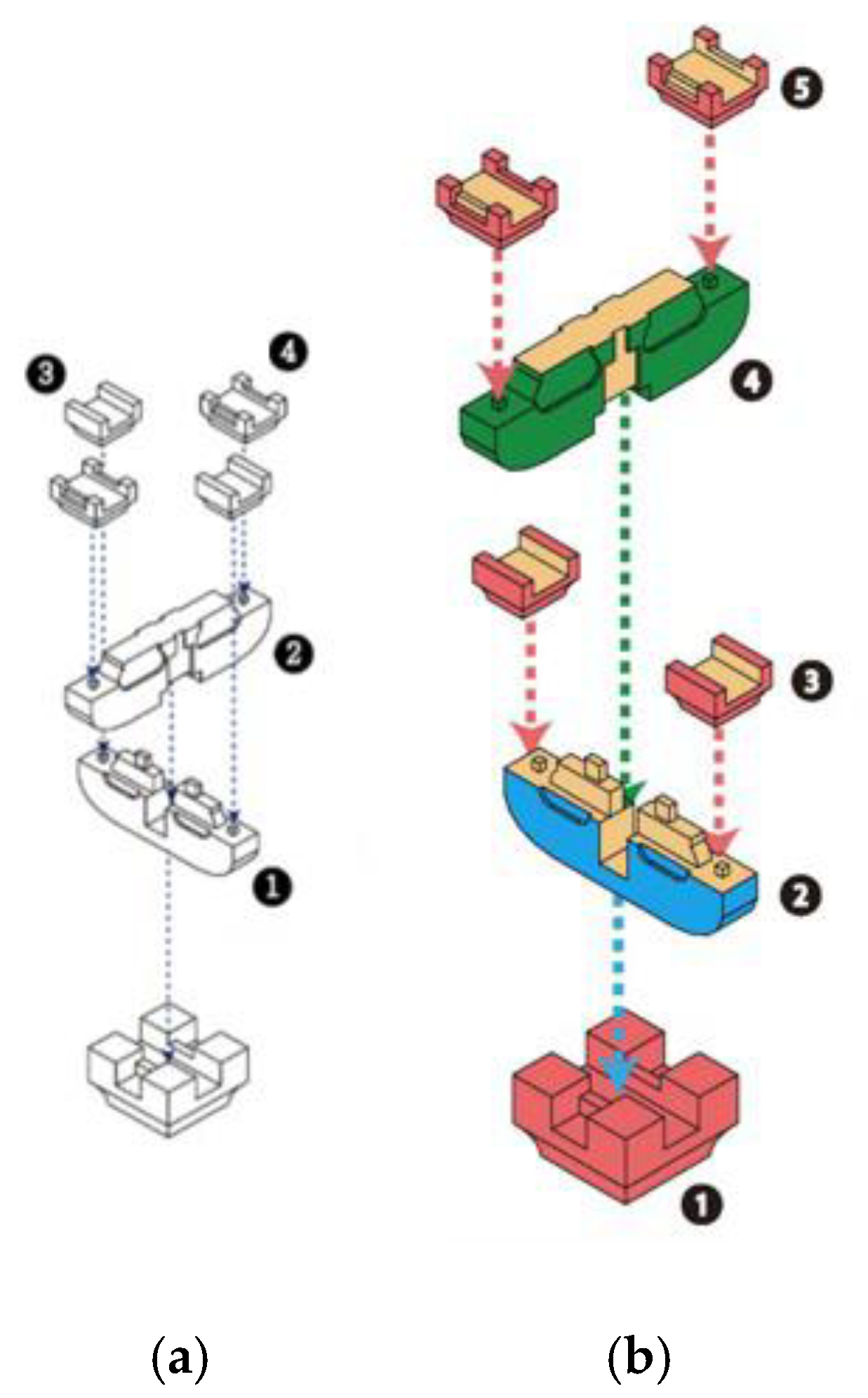
The second limitation was that the instructional arrows in the manual were unorganized. The purpose of arrows was to clearly indicate either a step-by-step walkthrough (with the arrows “flowing” chronologically) or the assembly feature of a part. However, a few subjects expressed that the arrows were ambiguous, and some of them were redundant in the current instructions. They suggested that the arrows be color-coded in order to convey information clearly. Figure 3 shows the differences between the original manual and improved version. Similar design improvements were also implemented in the AR assembly functions developed later.
4. Major Assisted Functions
The preliminary experiments showed that the performance of the manual assembly was indeed impacted by how the instructive information was presented to the user. Regardless of the presentation media (paper or computer), assembly instructions should precisely indicate what components to use and how they need to be assembled in 3D space [16]. In this study, two categories of assistive functions were proposed: part search and assembly demonstration, to address these requirements accordingly. Each category is described as follows.
4.1. Part Search
- Interactive 3D model display: the 3D display of the components to be assembled is more intuitive than their 2D drawings. The user can rotate the component models freely to observe their details (such as assembly features) at different view angles. Such rotation functionality solves the possible ambiguity of presenting a model only at a fixed view angle in the paper-based instructions. The assembly result is presented using a similar method.
- Part identification with instant feedback: according to previous research [6], whether or not the user has chosen the correct part is critical in most assembly tasks. This is often a significant reason for the prolonged assembly process. A part identification function implementing automatic object recognition was proposed to solve this problem. The identification result can guide the user to choose correct components through an AR interface. A typical use scenario of this function is that the user places an actual component in front of a camera, and the system determines whether the component is correct for the current assembly step. A confirmation message is instantly sent back to the user. This design can reduce the possibility of human cognition errors.
4.2. Assembly Demonstration
- Stepwise color labeling: This information presentation method was proposed in a previous study [17] for state awareness during a complex process. The subjects participating in the experiments also confirmed the effectiveness of this design. The component models newly added at the current step are coded in a color different from that of the existing models. The user can visualize the correct orientation and position of the new parts with respect to the others.
- AR animation: Hou et al. [18] suggested that displaying assembly animation containing both 3D models and real components helps users understand their size proportion and relative position/orientation in 3D space. This method follows a similar AR concept that combines virtual information with a real scene. The part models and real components usually have mutual occlusions when placing them in the same coordinate system. Occlusion processing is applied to hide rear portions, in order to produce a high visualization quality of the combined scene.
- Two assembly assisted systems that implement the above functional designs were proposed (see Figure 4). The first system mainly contains the interactive 3D model display and stepwise color labeling functions. A 3D animation demonstrates the component models and assembly process to the user. The second version includes a part identification function, which confirms the user’s component selection by giving instant feedback. It also shows the assembly process by aligning the part models precisely with the actual components in an AR animation. The AR system provides additional assistance supported by object recognition and spatial reasoning intelligence. Table 1 lists the assisted functions provided by paper-based instructions and the two systems.
4.3. Three-Dimensional Viewer-Based System
Figure 5 shows the framework design of the 3D viewer-based system. Unity was adopted as the software platform for implementing its functions. Unity is a 3D programming engine that supports Windows, macOS, and Linux operating systems and deploys applications compatible with mobile operating systems such as Android and iOS. It provides interactive programming graphical user interfaces that facilitate 3D scene construction, model rendering, and 3D manipulation. Developers can integrate third-party libraries in C# as a plug-in into their software development.
The hardware devices involved in this study consist of two parts. The development of Unity applications was mainly conducted in a desktop personal computer (PC). Its specifications are listed as follows: Intel Core-I5 6500 processor (3.2GHz), 8 GB memory, 300 GB hard drive, Graphics 530, and NVIDIA GeForce GTX950. The assisted functions were deployed in a smartphone, Zenfone3 ZE520KL, which interacted with the user during the assembly process. The phone has a 5.5’’ screen with a 1920 × 1080 pixel image resolution. The device uses the Android 6.0 Marshmallow operating system and is equipped with a Qualcomm Snapdragon 2 GHz eight-core processor.
The 3D viewer-based system starts by showing the first part model on the screen of a mobile phone that is set up on a work table using a tripod. Clicking on the next button, as shown in Figure 6, displays the next component to be assembled and changes the process to the next step. The user has two options at this point: (1) repeat the display of the assembly result, and (2) start assembling the actual components. The view angle of the scene can be freely changed at any time by clicking the button on the right side at the bottom of the screen. Once the current step is completed, the user will need to click the next button to enter into the next step. A similar operation repeats until the entire assembly process is completed. There is a sign at the left upper corner showing the current status of the assembly process. It is a common technique of the user interface design.
4.4. Augmented Reality (AR)-Based System
Figure 7 shows the framework design of the AR-based system. Compared to the 3D viewer version, this one provides intelligent functions that prevent the user from taking or recognizing incorrect parts. The user learns the assembly task from an AR animation that precisely superimposes virtual models with real components in 3D space. Occlusion processing is applied to the animation using the Z-buffer method [19] based on the depth data captured using a commercial RGB-D camera, Kinect 2. The Kinect device generates the ambient intelligence required by 3D object recognition and tracking, i.e., the ability to estimate which objects exist in the environment.
In computer graphics, occlusion culling is the process used to determine which models and parts of models are not visible from a certain viewpoint. In AR scenes, not only among virtual models, occlusions also occur between virtual models and real objects in a scene. In this work, the result of occlusion culling between real parts and the virtual model displayed for assembly is highly relevant to influencing the user’s spatial reasoning. The Kinect v2 device was installed in front of the worktable to capture the depth information of real parts in 3D space. Based on the depth data, the Z-buffering method decides which elements of a rendered scene are visible, and which are hidden.
Vuforia [20] is an object recognition library designed for AR applications and commonly used in the industry. This library provides an automatic object recognition functionality supported by learning models. Compatible with Unity, it helps streamline the development complexity and extend its real-world applications. Vuforia builds the recognition function of an object from training data that provide salient feature information for constructing the underlying learning model.
The feature information may come from various object attributes such as geometry, color, and texture. Unfortunately, the original Dougong models are made of wood and lack discernible contrast in their appearance (see Figure 8a). Thus, additional information needs to be added to enhance the identification ability of the training model. When observing the actual Dougong architecture, it was discovered that some of the enamels were decorated with various colored patterns. Similar decorative patterns were designed and attached to the Dougong models in cooperation with an experienced designer. The result can be seen in Figure 8b. These patterns provide the feature information required to build the object recognition ability. They implicitly enable the marker tracking of the Dougong components, the performance of which is more stable than markerless tracking.
The AR system starts by showing the first component model on the screen. It preserves most design features implemented in the 3D viewer system. The user can freely change the view angle of the models during the assembly process. The color labeling helps distinguish parts between different assembly steps. The click button controlling the assembly status remains the same. One newly added function is the automatic part confirmation. The user places the part (which they considered the one to be assembled) in front of the smartphone camera. The system will enquire from the learning model and send out a message to indicate whether that part is the correct one. This function prevents the user from taking a wrong part. When the system recognizes the correct part, it will confirm with a “correct” message and start to display an AR animation that demonstrates the assembly process, as shown in Figure 9. Once the current step is completed, the user will need to click the next button to take the next step. A similar operation repeats until the entire assembly process is completed.
5. User Study
5.1. Experiment Design
A series of experiments were conducted to compare the proposed two systems with paper-based instructions. In total, 48 engineering students with ages ranging from 20 to 25 years participated in the experiments. They were randomly divided into three test groups, each consisting of 16 students (of whom, half were male and half were female). In order to avoid the learning effect, the subjects in one group only performed the assembly process using one assisted method. The experimenter described the experimental purpose and procedure during the first session. The focus was to demonstrate the basics of assembling the Dougong models to the subjects. They also became aware that both the assembly time and accuracy would be measured, with accuracy as the priority. The second session explained how the two systems operate. Subjects learned the system functions and process flow during a practice period. For the non-paper systems, the practice objective was to form a cube from four simple elements with color patterns (see Figure 10). In the last session, the actual assembly experiment was conducted in a controlled environment. People were not allowed to talk during the experiment. The entire assembly process was video-recorded. After the experiment, the subjects filled out the NASA-TLX questionnaire. An interview was conducted to understand their opinions of the various assisted media. Extra feedback about the systems was collected during the interview. Figure 11 shows the experimental environment and a series of images during an AR-assisted experiment session.
5.2. Analysis of Experimental Data
The experimental data were analyzed with both objective and subjective measures. The former evaluated the experimental process using the video clip recorded. The quantitative results included the time spent and errors committed by the subjects in each assembly step. The two assisted systems and paper-based instructions contain different assembly steps, described as follows:
- Part recognition: the user identifies the part with the information provided in different media. The time spent in this step is estimated from the end of the previous step to the moment that the user’s eyesight left the information.
- Part fetching: the user selects, grasps, and moves the part from the storage area to the work area.
- Part confirmation: only the AR-based system has this step, where the system confirms that the part taken by the user is the correct one.
- Assembly confirmation: only the AR-based system has this step, where the system confirms that the current assembly step is properly completed.
- Task recognition: the user comprehends the assembly process. The time is measured from the time when the user takes the part to when the assembly starts.
- Assembly: the time is measured from when the user starts to assemble to the moment that the “Next” button is clicked.
This study differs from previous studies in that not only the time spent by the part identification and assembly steps was explored, but also the time consumed by the user to comprehend the assembly instructions. It was observed that after the participant had chosen the correct part, they still had to read the instructions in order to assemble the part in the correct position and orientation. Most subjects seemed unfamiliar with the Dougong assembly despite the demonstration given to them. The time spent in understanding the instructive information revealed a subject’s cognitive processing time (before the actual assembly). It also helped evaluate the efficiency and effectiveness of the assisted functions provided.
Radkowski et al. [7] classified the errors of the manual assembly into the part orientation and position errors. In this study, two additional error types are proposed based on the observation during the Dougong assembly: part fetching error and incomplete assembly. The former refers to the situation in which the user fetches a wrong part. This error may occur owing to the user’s incorrect recognition of the part to be assembled, or mistakenly fetching a wrong one from the part storage. Incomplete assembly indicates that the assembly task is not properly accomplished with the parts not aligned precisely or their relative position not achieved.
As mentioned previously, a post-experiment assessment using the NASA-TLX questionnaire [9] was conducted to subjectively evaluate the workload while using the systems. The subjects were interviewed and their feedbacks regarding the experiment were collected. A one-way analysis of variance (one-way ANOVA) was applied to analyze the following factors: the time of each assembly step, the assembly errors, and the questionnaire score for the paper-based instructions and the two AR systems. If a statistically significant difference exists in the ANOVA, Scheffe’s method [21] is then used for detailed comparisons. It compares all possible simple and complex pairs of means with a narrower confidence interval.
5.3. Experimental Results
5.3.1. Assembly Time
The experimental result of assembly time is summarized in Table 2. The average total assembly time for the paper-based instructions, 3D viewer, and AR-based systems was 358.5, 366.9, and 781.9 s, respectively. The AR-assisted assembly consumed the longest time. The one-way ANOVA showed that there is a statistically significant difference between the three results, F(2, 45) = 49.313, p < 0.005 (see Table 3). The post-hoc analyses using the Scheffé test indicated that the average assembly time was significantly shorter in the paper group (mean (M) = 358.50, standard deviation (SD) = 102.48) than in the AR group (M = 781.88, SD = 195.02), F(1, 45) = 25.32, p < 0.005. The average assembly time was significantly shorter in the 3D viewer group (M = 366.94, SD = 92.14) than in the AR group, F(1, 45) = 17.65, p < 0.005.
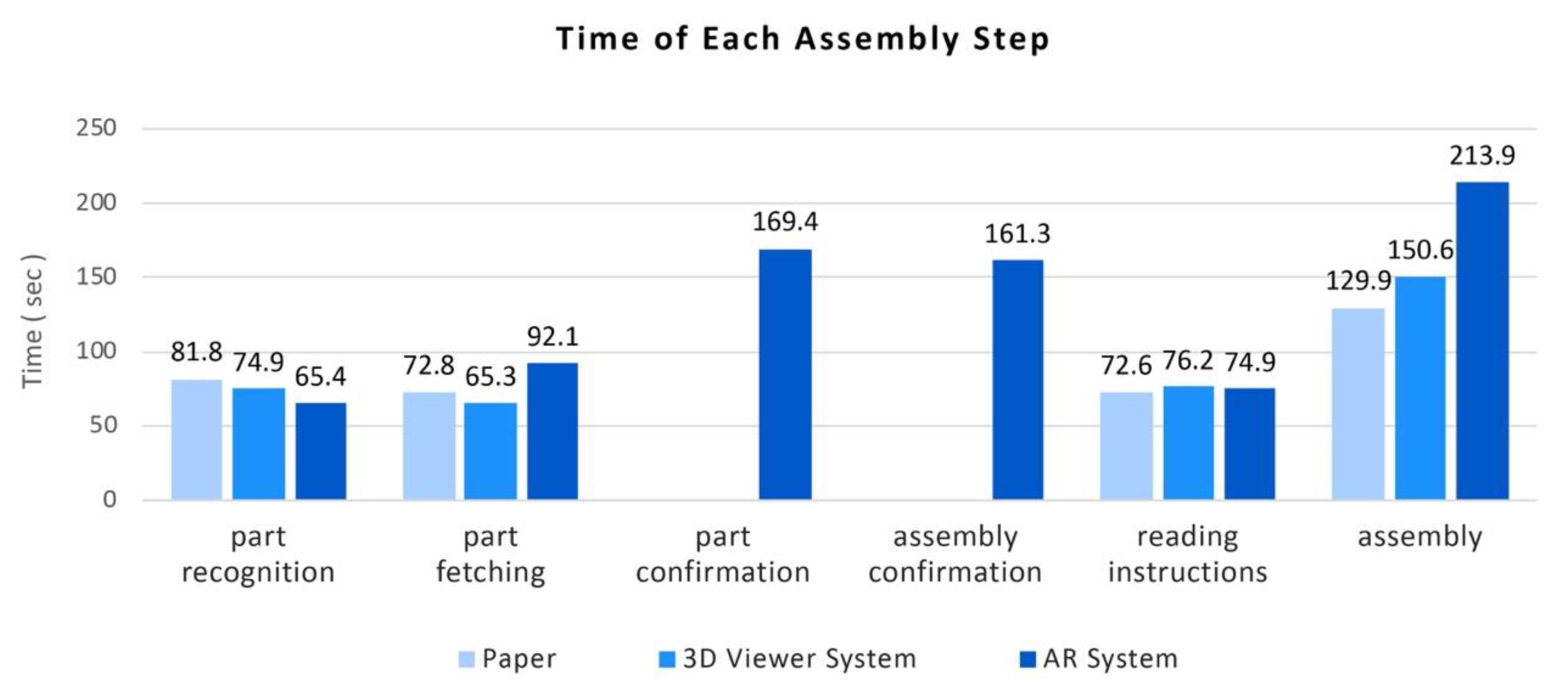
Next, the total assembly time was decomposed into six steps (see Section 5.2) for in-depth analyses. Table 4 lists the experimental result of each step. As shown in Figure 12, for the paper form, the part recognition step consumed the longest time (81.8 s). For the part-fetching step, the AR system took the longest average time (92.1 s). Only the AR system has the next two steps. The 3D viewer system required the longest time in the task recognition step (76.2 s). The AR system yielded the longest time in the actual assembly step. The ANOVA result showed a significant difference among three groups only in the assembly step, F(2, 45) = 15.23, p < 0.00.
5.3.2. Assembly Error
The experimental result of assembly errors is summarized in Table 5. The average number of errors that occurred during the entire assembly was 4.25, 3.00, and 2.31, respectively. The ANOVA showed that only a marginally significant difference exists between the three results, F(2, 45) = 2.99, p = 0.05 (see Table 6). We then conducted the analysis on individual errors. The result showed a significant difference only in the fetching error, F(2, 45) = 4.92, p = 0.012. The post-hoc analyses using the Scheffé test showed that the paper group (M = 4.25, SD = 2.93) induced more errors than the two other systems: 3D viewer (M = 3.00, SD = 1.79), F(1, 45) = 0.439, p = 0.024 and AR (M = 2.31, SD = 1.92), F(1, 45) = 0.439, p = 0.047. The experimental result of each error is listed in Table 7. As shown in Figure 13, regarding the other three error types, although the AR-based system had consistently yielded the lowest number of errors when compared to the others, their difference was not statistically significant.
5.3.3. NASA-TLX Score
As shown in Figure 14, the 3D viewer system has the highest NASA-TLX score (35.1), followed by the AR system (32.1) and the paper form (25.8). However, the one-way ANOVA showed that their differences are not statistically significant, F(2, 45) = 1.91, p = 0.16. The scores of six dimensions are listed in Table 8. The 3D viewer system has the highest score in mental demand, while the AR system has the highest score in physical demand.
5.4. Observations and Discussions
The paper-based instructions yielded a NASA-TLX score relatively lower than the other forms, although there was no statistically significant difference among them. The result was similar to the finding of a previous study [16]. This result may indicate that people are still accustomed to the paper presentation. Note that the usability of the paper-based instructions had been re-designed and improved based on the preliminary experimental result. The improvements included clearer illustrations for the scale and shape of the components, the component orientation while assembling, and color-coded arrows indicating the assembly features. Few subjects implied that they experienced difficulties in determining the part orientation and position using the paper-based instructions.
As for the 3D viewer system, some subjects expressed concern that differentiating between part models and identifying the actual part corresponding to their virtual model were difficult. This may be the reason that the 3D viewer system showed the highest score in mental load. All the subjects had no prior experience of using a similar assisted system. They might thus need additional time and effort to learn how to operate the system functions.
Most of the subjects in the experiments considered the part confirmation and assembly demonstration function highly useful. They indicated that the AR animation was effective in helping them understand the assembly task and estimating the dimensions of the actual components. Most users emphasized that it was more intuitive than the 3D viewer system that only displays virtual models. For the drawbacks of the AR-based system, some subjects expressed that placing the parts and assemblies under the camera fixed in the test environment caused them physical fatigue. They felt physically and mentally tired by repetitively holding parts under the camera for confirmation purposes. The highest physical demand in the NASA-TLX questionnaire somehow reflects this problem. The usage of HMD goggles frees the hands of the user and may, therefore, solve the aforementioned problem. The slow recognition speed sometimes frustrated the subjects. This also contributed to the longer total assembly time than the other two forms.
6. Conclusions
In this work, the manual assembly of the Dougong structure supported by AR interactive contents was studied. The frameworks for two computer-assisted systems that have different degrees of intelligence were designed. Both systems consisted of two categories of assisted functions: part search and assembly demonstration. A series of manual assembly experiments were conducted to compare three assistance methods (paper, 3D viewer, and AR) in terms of assembly efficiency and accuracy. The experimental results were analyzed using both objective and subjective measures. The former included the time spent in each of the six steps: part recognition, part fetching, part confirmation, assembly confirmation, task recognition, and assembly. A second objective measure estimated the number of errors in each type: part position, part orientation, part fetching error, and incomplete assembly. NASA-TLX questionnaires and interviews with the subjects provided the subjective assessment. Essential experimental findings include:
- Traditional paper-based instructions only show part models in a single view and their proportion to actual components are ambiguous. Although participants expressed no difficulties in determining the orientation and position from the paper-based instructions, they committed more position and orientation errors with the paper than the AR system. People may well understand the instruction drawings in 2D and the spatial relationship of different parts shown in one single view. Such a visual perception does not necessarily assure the success of a real assembly task, which often requires 3D reasoning from multiple view angles.
- The number of errors made by the AR-based system was the least. This result may be achieved with the part and assembly confirmation functions. Automatic result verification is thus a useful functional feature for computer-assisted assembly systems. Implementation of this feature should consider the assembly time, errors, and system workload simultaneously. The current design needs to be improved to reduce the computational time required by object recognition. To apply deep learning for pose estimation of 3D models from a single RGB image is a feasible solution. Traditional template matching methods such as LINEMOD [22] is also applicable.
- Most subjects considered the AR-based system useful and intuitive in assisting the manual assembly of the Dougong models. The interactive display of 3D models allowed them to visualize the part details by freely adjusting the view angle. They agreed that the part and assembly confirmation functions can prevent the users from taking the wrong components.
- To incorporate the similar confirmation functions into the 3D viewer or paper-based method is worth pursuing. The implementation would be problematic with potentially poor process flow or usability. AR serves as a more effective interface in this regard.
In this study, the practicality of AR in assisting manual assembly of complex structures was verified. However, the subjects suggested several functional improvements to the current AR functions after the experiments. The object recognition process needs to be shortened to enhance the assembly efficiency and user’s workload. Adopting AR goggles may be able to reduce the physical stress caused by the current system. In future works, the assisted assembly functions can be investigated using the see-through video mode (goggles) versus the monitor-based mode (screen). It would be interesting to compare learnability after the assembly experience using different methods.
Author Contributions
Conceptualization, C.-H.C.; Data curation, C.-J.L.; Investigation, C.-H.C. and C.-J.L.; Methodology, C.-H.C. and S.-C.L.; Software, C.-J.L.; Validation, C.-J.L.; Writing—original draft, C.-H.C.; Writing—review & editing, S.-C.L. All authors have read and agreed to the published version of the manuscript.
Funding
This research was funded by Taiwan MOST grant number 108-2221-E-007 -007 -MY3.
Conflicts of Interest
The authors declare no conflict of interest.
References
- Liang, S.C. Chinese Architecture: A Pictorial History; Dover Publications: Mineola, NY, USA, 2005. [Google Scholar]
- Chu, C.H.; Cheng, C.H.; Wu, H.S.; Kuo, C.C. A Cloud Service Framework for Virtual Try-on of Footwear in Augmented Reality. J. Comput. Inf. Sci. Eng. 2019, 19, 021002–021009. [Google Scholar] [CrossRef]
- Caudell, T.P.; Mizell, D.W. Augmented reality: An application of heads-up display technology to manual manufacturing processes. In Proceedings of the Twenty-Fifth Hawaii International Conference on System Sciences, Kauai, HI, USA, 7–10 January 1992; Volume 2, pp. 659–669. [Google Scholar]
- Korn, O.; Schmidt, A.; Hörz, T. Augmented manufacturing: A study with impaired persons on assistive systems using in-situ projection. In Proceedings of the 6th International Conference on Pervasive Technologies, Rhodes, Greece, 29–31 May 2013; pp. 21–28. [Google Scholar]
- Hou, L.; Wang, X. A study on the benefits of augmented reality in retaining working memory in assembly tasks: A focus on differences in gender. Autom. Constr. 2013, 32, 38–45. [Google Scholar] [CrossRef]
- Syberfeldt, A.; Danielsson, O.; Holm, M.; Wang, L. Visual assembling guidance using augmented reality. Procedia Manuf. 2015, 1, 98–109. [Google Scholar] [CrossRef]
- Radkowski, R.; Herrema, J.; Oliver, J. Augmented reality-based manual assembly support with visual features for different degrees of difficulty. Int. J. Hum. Comput. Interact. 2015, 31, 337–349. [Google Scholar] [CrossRef]
- Funk, M.; Kosch, T.; Greenwald, S.W.; Schmidt, A. A benchmark for interactive augmented reality instructions for assembly tasks. In Proceedings of the 14th International Conference on Mobile and Ubiquitous Multimedia, Linz, Austria, 30 November–2 December 2015; pp. 253–257. [Google Scholar]
- Funk, M.; Kosch, T.; Schmidt, A. Interactive worker assistance: Comparing the effects of in-situ projection, head-mounted displays, tablet, and paper instructions. In Proceedings of the ACM International Joint Conference on Pervasive and Ubiquitous Computing, Heidelberg, Germany, 12–16 September 2016; pp. 934–939. [Google Scholar]
- Young, T.C.; Smith, S. An interactive augmented reality furniture customization system. In Proceedings of the International Conference on Virtual, Augmented and Mixed Reality, Toronto, ON, Canada, 17–22 July 2016; pp. 662–668. [Google Scholar]
- Loch, F.; Quint, F.; Brishtel, I. Comparing video and augmented reality assistance in manual assembly. In Proceedings of the IEEE International Conference on Intelligent Environments, London, UK, 14–16 September 2016. [Google Scholar]
- Henderson, S.J.; Feiner, S.K. Augmented Reality in the Psychomotor Phase of a Procedural Task. In Proceedings of the 10th IEEE International Symposium on Mixed and Augmented Reality, Basel, Switzerland, 26–29 October 2011; pp. 191–200. [Google Scholar]
- Hoover, M.; Miller, J.; Gilbert, S.; Winer, E. Measuring the Performance Impact of using the Microsoft HoloLens 1 to Provide Guided Assembly Work Instructions. J. Comput. Inf. Sci. Eng. 2020, 1–28. [Google Scholar] [CrossRef]
- Alves, J.; Marques, B.; Oliveira, M.; Araújo, T.; Dias, P.; Santos, B.S. Comparing Spatial and Mobile Augmented Reality for Guiding Assembling Procedures with Task Validation. In Proceedings of the IEEE International Conference on Autonomous Robot Systems and Competitions (ICARSC), Porto, Portugal, 24–26 April 2019; pp. 1–6. [Google Scholar]
- Bhattacharya, B.; Winer, E.H. Augmented reality via expert demonstration authoring (AREDA). Comput. Ind. 2019, 105, 61–79. [Google Scholar] [CrossRef]
- Blattgerste, J.; Renner, P.; Strenge, B.; Pfeiffer, T. In-Situ Instructions Exceed Side-by-Side Instructions in Augmented Reality Assisted Assembly. In Proceedings of the 11th PErvasive Technologies Related to Assistive Environments Conference, Corfu, Greece, 26–29 June 2018. [Google Scholar]
- Chen, Z.R.; Liao, C.J.; Chu, C.H. An Assembly Guidance System of Tou Kung Based on Augmented Reality. In Proceedings of the International Conference of the Association for Computer-Aided Architectural Design Research in Asia, Beijing, China, 17–19 May 2018. [Google Scholar]
- Hou, L.; Wang, X.; Bernold, L.; Love, P.E. Using Animated Augmented Reality to Cognitively Guide Assembly. J. Comput. Civ. Eng. 2013, 27, 439–451. [Google Scholar] [CrossRef]
- OpenGL. Available online: https://www.opengl.org/ (accessed on 25 February 2020).
- Vuforia. Available online: https://www.vuforia.com/ (accessed on 25 February 2020).
- Milliken, G.A.; Johnson, D.E. Analysis of Messy Data; CRC Press: Boca Raton, FL, USA, 1993. [Google Scholar]
- Hinterstoisser, S.; Holzer, S.; Cagniart, C.; Ilic, S.; Konolige, K.; Navab, N.; Lepetit, V. Multimodal Templates for Real-Time Detection of Texture-Less Objects in Heavily Cluttered Scenes. In Proceedings of the IEEE International Conference on Computer Vision, Barcelona, Spain, 6–13 November 2011; pp. 858–865. [Google Scholar]
Figure 1.
Dougong architecture.

Figure 2.
Paper-based instructions used in preliminary experiments.

Figure 3.
Improved paper-based assembly instructions: (a) original form and (b) improved version.

Figure 4.
Two augmented reality (AR)-assisted systems.

Figure 5.
Framework design of 3D viewer-based system.

Figure 6.
Screenshots of assembly demonstration function.

Figure 7.
Framework design of AR-based system.

Figure 8.
(a) Original Dougong models and (b) models decorated with colored patterns.

Figure 9.
(a) System confirms the correct part and (b) displays the assembly process through AR animation.
Figure 9.
(a) System confirms the correct part and (b) displays the assembly process through AR animation.

Figure 10.
Practice session to form a cube from four simple elements.

Figure 11.
(a) Experimental environment and (b) a typical AR-assisted experiment session.

Figure 12.
Time of each assembly step for the paper, 3D viewer, and AR assistance.

Figure 13.
Numbers of various errors for the three forms.

Figure 14.
Average NASA-TLX scores of the three forms.


Table 1.
Assisted functions provided by three media.
| Function | Paper-Based | 3D Viewer | AR |
|---|---|---|---|
| Interactive 3D model display | no | yes | yes |
| Part identification with feedback | no | no | yes |
| Stepwise color labeling | yes | yes | yes |
| AR animation | no | no | yes |
Table 2.
Experimental result of total assembly time in seconds.
| Media | # of Data | Average | Standard Deviation | Min | Max |
|---|---|---|---|---|---|
| Paper | 16 | 358.50 | 102.48 | 247 | 608 |
| 3D Viewer | 16 | 366.94 | 92.14 | 227 | 496 |
| AR | 16 | 781.88 | 195.02 | 588 | 1373 |
Table 3.
The analysis of variance (ANOVA) result of the total assembly time.
| SS | df | MS | F | p | |
|---|---|---|---|---|---|
| Between | 1,874,617.125 | 2 | 937,308.563 | 49.313 | 0.000 |
| Within | 855,334.688 | 45 | 19,007.438 | ||
| Total | 2,729,951.813 | 47 |
Table 4.
Experimental result of each step time in seconds.
| Media | Average | Standard Deviation | Min | Max | |
|---|---|---|---|---|---|
| Part recognition | Paper | 81.75 | 40.783 | 38 | 165 |
| 3D Viewer | 74.94 | 28.034 | 32 | 119 | |
| AR | 65.44 | 35.946 | 37 | 185 | |
| Part fetching | Paper | 72.81 | 37.422 | 38 | 190 |
| 3D Viewer | 65.25 | 20.479 | 24 | 96 | |
| AR | 92.06 | 47.799 | 51 | 257 | |
| Instructions reading | Paper | 72.63 | 41.326 | 32 | 183 |
| 3D Viewer | 76.19 | 38.840 | 38 | 166 | |
| AR | 74.94 | 23.561 | 46 | 133 | |
| Assembly | Paper | 129.94 | 40.321 | 78 | 218 |
| 3D Viewer | 150.56 | 43.411 | 89 | 255 | |
| AR | 213.94 | 50.301 | 145 | 347 |
Table 5.
Experimental result of assembly errors (units: # of times).
| Media | Average | Standard Deviation | Min | Max |
|---|---|---|---|---|
| Paper | 4.25 | 2.93 | 0 | 12 |
| 3D Viewer | 3.00 | 1.79 | 1 | 8 |
| AR | 2.31 | 1.92 | 0 | 7 |
Table 6.
The ANOVA result of assembly errors.
| SS | df | MS | F | p | |
|---|---|---|---|---|---|
| Between | 30.875 | 2 | 15.438 | 2.989 | 0.05 |
| Within | 232.438 | 45 | 5.165 | ||
| Total | 263.313 | 47 |
Table 7.
Experimental result of various errors (units: # of times).
| Media | Average | Standard Deviation | Min | Max | |
|---|---|---|---|---|---|
| Part fetching error | Paper | 2.56 | 1.632 | 0 | 7 |
| 3D Viewer | 1.31 | 1.014 | 0 | 4 | |
| AR | 1.44 | 0.964 | 0 | 3 | |
| Position error | Paper | 0.38 | 0.719 | 0 | 2 |
| 3D Viewer | 0.50 | 0.632 | 0 | 2 | |
| AR | 0.13 | 0.342 | 0 | 1 | |
| Orientation error | Paper | 0.94 | 0.998 | 0 | 3 |
| 3D Viewer | 0.88 | 0.885 | 0 | 3 | |
| AR | 0.44 | 0.727 | 0 | 2 | |
| Incomplete assembly | Paper | 0.38 | 0.619 | 0 | 2 |
| 3D Viewer | 0.31 | 0.602 | 0 | 2 | |
| AR | 0.31 | 0.602 | 0 | 2 |
Table 8.
NASA-TLX sub-scores of the three forms.
| Mental | Physical | Temporal | Performance | Effort | Frustration | |
|---|---|---|---|---|---|---|
| Paper | 30.18 | 13.68 | 29.21 | 25.65 | 18.94 | 12.73 |
| 3D Viewer | 47.97 | 19.03 | 30.47 | 44.13 | 22.25 | 17.75 |
| AR | 32.88 | 30.34 | 27.28 | 37.88 | 19.78 | 19.28 |
© 2020 by the authors. Licensee MDPI, Basel, Switzerland. This article is an open access article distributed under the terms and conditions of the Creative Commons Attribution (CC BY) license (http://creativecommons.org/licenses/by/4.0/).
Share and Cite
MDPI and ACS Style
Chu, C.-H.; Liao, C.-J.; Lin, S.-C. Comparing Augmented Reality-Assisted Assembly Functions—A Case Study on Dougong Structure. Appl. Sci. 2020, 10, 3383. https://0-doi-org.brum.beds.ac.uk/10.3390/app10103383
AMA Style
Chu C-H, Liao C-J, Lin S-C. Comparing Augmented Reality-Assisted Assembly Functions—A Case Study on Dougong Structure. Applied Sciences. 2020; 10(10):3383. https://0-doi-org.brum.beds.ac.uk/10.3390/app10103383
Chicago/Turabian StyleChu, Chih-Hsing, Chien-Jung Liao, and Shu-Chiang Lin. 2020. "Comparing Augmented Reality-Assisted Assembly Functions—A Case Study on Dougong Structure" Applied Sciences 10, no. 10: 3383. https://0-doi-org.brum.beds.ac.uk/10.3390/app10103383
Note that from the first issue of 2016, this journal uses article numbers instead of page numbers. See further details here.