Design of Railway Track Model with Three-Dimensional Alignment Based on Extended Industry Foundation Classes


1
Department of Civil and Environmental Engineering, Yonsei University, Seoul 03722, Korea
2
Department of Civil, Environmental, and Architectural Engineering, University of Colorado Boulder, Boulder, CO 80309, USA
*
Author to whom correspondence should be addressed.
Appl. Sci. 2020, 10(10), 3649; https://0-doi-org.brum.beds.ac.uk/10.3390/app10103649
Submission received: 24 April 2020
/
Revised: 14 May 2020
/
Accepted: 21 May 2020
/
Published: 25 May 2020
(This article belongs to the Section Civil Engineering)
Abstract
:Featured Application
The methodology proposed herein can be used for comprehensive modeling of alignment-based structures, such as railway tracks and roads, based on extended industry foundation classes.
Abstract
Building information modeling (BIM) has been widely applied in conjunction with the industry foundation class (IFC) for buildings and infrastructure such as railways. However, a limitation of the BIM technology presents limitations that make designing the three-dimensional (3D) alignment-based information models difficult. Thus, the time and effort required to create a railway track model are increased, while the reliability of the model is reduced. In this study, we propose a methodology for developing an alignment-based independent railway track model and extended IFC models containing railway alignment information. The developed algorithm using BIM software tools allows for a discontinuous structure to be designed. The 3D alignment information connects different BIM software tools, and the classification system and IFC schema for expressing railway tracks are extended. Moreover, the classification system is fundamental for assigning IFC entities to railway components. Spatial and hierarchical entities were created through a developed user interface. The proposed methodology was implemented in an actual railway track test. The possibility of managing IFC-based railway track information, including its 3D alignment information, was confirmed. The proposed methodology can reduce the modeling time and can be extended to other alignment-based structures, such as roads.
1. Introduction
Building information modeling (BIM) has been widely employed in construction sites because it can facilitate schedule adjustments and quantity take-offs and can be used to design alternative reviews using three-dimensional (3D) information models [1,2,3]. An increasing number of countries are mandating the application of BIM in large construction projects. Europe has seen a 32% increase in the number of projects applying BIM between 2012 and 2017 [4]. The use of BIM has recently become indispensable in railway projects, wherein information management, information sharing, and collaboration serve as essential elements; for example, in Qatar (Qatar Rail), Hong Kong (Mass Transit Railway), and China (China Railway BIM Alliance), large railway projects are underway [5,6,7]. It is first necessary to create models containing accurate and reliable information which is consistent with the basic BIM philosophy; thus, users of BIM can reap its benefits [8]. Reliable construction information and information management methodologies are necessary for the implementation of BIM in large projects, such as public infrastructure facilities, where several stakeholders are involved in each stage of the life cycle. Furthermore, the reliability of the data is an essential feature [8,9]. However, BIM has been developed based on the floor-centered concept for buildings; therefore, it presents many limitations with respect to alignment-based structures, such as railways and roads [10]. The utilization of BIM is challenging in these contexts because the methodologies for creating 3D alignment-based component shapes have not yet been clearly established.
Numerous researchers have attempted to represent alignment-based infrastructure facilities using BIM-based information models. Sampaio [11] and Ji et al. [12] proposed methods to represent the shapes of 3D alignment-based bridges using parametric modeling. Amann et al. [13] created a model to represent 3D alignment-based roadways. Some BIM software companies, including Autodesk, have developed various BIM authoring tools (BATs) in the form of software to represent information models; however, implementing these tools for 3D alignment remains challenging because their functions are specialized toward describing buildings [10]. Alignment-centered modeling tools (AMTs) targeted at alignment-based design, such as Autodesk’s Civil 3D and Bentley System’s Power Rail Track, have been developed. However, AMTs cannot independently represent discontinuous structures, such as sleepers, because the software is oriented toward design parameters rather than 3D objects, and its shape-creation method focuses on continuous structures belonging to the alignment. To address these problems, constructing BIM systems using software specialized for the intended purpose is more effective than using a specific BIM software program, as suggested by Lee et al. [14]. Neves, et al. [15] attempted to create a usable railway structure model by linking an AMT with a BAT; however, the model created using the AMT was not fully recognized by the BAT, and the semantic information of the structure could not be identified. This lack of interoperability between the BIM software and the difficulties of linkage between different data files makes the modeling process and the application of BIMs challenging for actual projects [16]. Therefore, efforts have been made to improve the information compatibility for data exchange through various methods [17,18,19,20].
One method of securing interoperability is establishing data standards for BIM utilization [9]. ISO-TC59/SC13 industry foundation classes (IFC) [21], developed by the Model Support Group of buildingSMART International (bSI), is an object-oriented conceptual model that aims to secure interoperability through its open format. IFC focuses on representing and managing building-oriented information because the previous targets of BIM have been buildings; however, there has been a consistent demand for the application of IFC to facilities other than buildings. Accordingly, many researchers have proposed methods for applying IFC to alignment curves and infrastructure facilities such as bridges and tunnels [22,23,24,25]. bSI also intended to extend IFC to various facilities; it officially announced the latest version of the schema (IFC4 × 2), in which alignment elements had been added to the existing schema [26]. However, IFC4 × 2 still presents an insufficient number of elements for representing railway track information, and its expansion is difficult because methodologies for converting it into a model based on the existing IFC schema have not been established yet. In contrast, BIM software supports the creation of a railway structure but cannot connect the object to a new IFC entity. Lee et al. [27] proposed a methodology to convert a model based on the existing IFC into a model based on the extended IFC by inputting the physical and spatial information of model elements into a user-defined property set. This method can be useful in areas where IFC standards have not been established yet; however, it is time-consuming and requires highly skilled operators because users need to insert information for each component. Gao et al. [28] performed a schema extension for the creation of railway track information models and represented railway structures using the developed software; however, this method requires the user to invest considerable time and effort in representing each component because individual algorithms need to be created. Conversely, the method of generating an information model for a horizontal structure using alignment information and converting it into a suitable extended IFC element enables the generation of a railway track model regardless of the skills of the modeler.
This study proposes a methodology to create IFC-based information models for 3D alignment-based railway tracks. The information models of railway tracks were created using the linkage between software. This methodology can also employ other functions of existing software because AMT and BAT software are linked via their alignment information; thus, the individual attributes of each object can be managed. The information models are converted into IFC-based information models that can secure interoperability. The railway components are semantically assigned identical IFC entities, which are extended by referring to a classification system. The proposed methodologies are applied to actual railway projects under construction, and their effectiveness is verified.
2. Limitations of Railway Infrastructure Information Model Creation Methods
One of the important differences between information model creation methods for infrastructure and buildings is the reference line for modeling. For example, in building-oriented 3D information modeling, objects are stacked level-upon-level based on a fixed area, whereas for road and railway facilities, objects are arranged and represented based on 3D alignment. The combination of various parameters along the direction of alignment or the line perpendicular to the alignment affects the shapes and arrangements of structures. Therefore, sufficient capacity must be provided to implement alignment and structure arrangements simultaneously and manage such information.
This type of railway alignment can be created using BIM tools, as illustrated in Figure 1a; however, it is inefficient for the representation of railway alignment for the following reasons:
- Railway alignment is designed using horizontal and vertical curves composed of straight lines, curves, and transition curves. BATs predominantly employ straight lines and circular curves but do not provide functions for combining the horizontal and vertical lines. Therefore, railway alignment information cannot be represented using such tools and is also not suitable for representing the shapes of structures that belong to the alignment.
- While buildings are designed based on the floor concept in a direction perpendicular to the ground, railway track structures are arranged using 3D alignment. Therefore, alignment information must be well-represented for railway track structures, and the information must be linked with such structures. However, with BAT software, it is difficult to create an alignment that includes railway alignment information and further link this information with the created structure.
AMT software that supports infrastructure alignment provides an environment in which straight lines, transition curves, and circular curves can be created as a single object [29]. Then, they construct a model using the two-dimensional (2D) cross-sections of the structures to be modeled in 3D, such as rails and roadbeds, as reference cross-sections. A method for creating solids by sweeping along the alignment is depicted in Figure 1b [30]. This method is effective for continuous objects, such as rails and ballasts; however, it presents the following limitations in terms of accurate representation of discontinuous objects, such as sleepers, fasteners, and joints.
- Railway alignment does not incorporate parameters for discontinuous objects, such as sleepers; instead, it considers them as a part of the continuous alignment. Therefore, the process of extracting parameters to be applied directly to sleepers is complicated.
- Problems regarding arrangement occur for discontinuous objects that follow 3D curves; it is difficult to generalize and reflect information regarding the angle between sleepers and the alignment, which is applied as a design parameter using AMTs. For example, the cant must be calculated at the location of each sleeper because this varies depending on its location in the alignment; however, it is difficult for AMTs to reflect the cant because AMTs cannot accurately represent discontinuous structures.
A method for linking AMTs and BATs is proposed herein to accurately represent railway tracks and related objects using information models and to modify or utilize such information where necessary. This method enables the realization of efficient AMTs and BATs for design parameter management and object management, respectively. The detailed methodology is described in the next section.
3. Modeling Methodology for Railway Track Structure Representation
3.1. Information Linkage between Software to Share Alignment Information
The components of the railway track can be categorized into (a) elements swept continuously according to the 3D alignment created in the design phase and (b) discontinuous elements arranged at regular intervals according to the object-creation perspective of 3D alignment. Elements represented by continuous sweeping include rails and ballasts and those that need to be represented separately include sleepers. These elements are arranged by referring to the alignment and lower object from the geometrical perspective. Certain elements change shape according to the cant. The former elements include all structures except for ballasts, whereas the latter elements can include ballasts according to the design concept. Therefore, structures that are arranged on ballasts depend on the locations of the ballasts, and elements of different shapes are required to ensure the safety of railway operations.
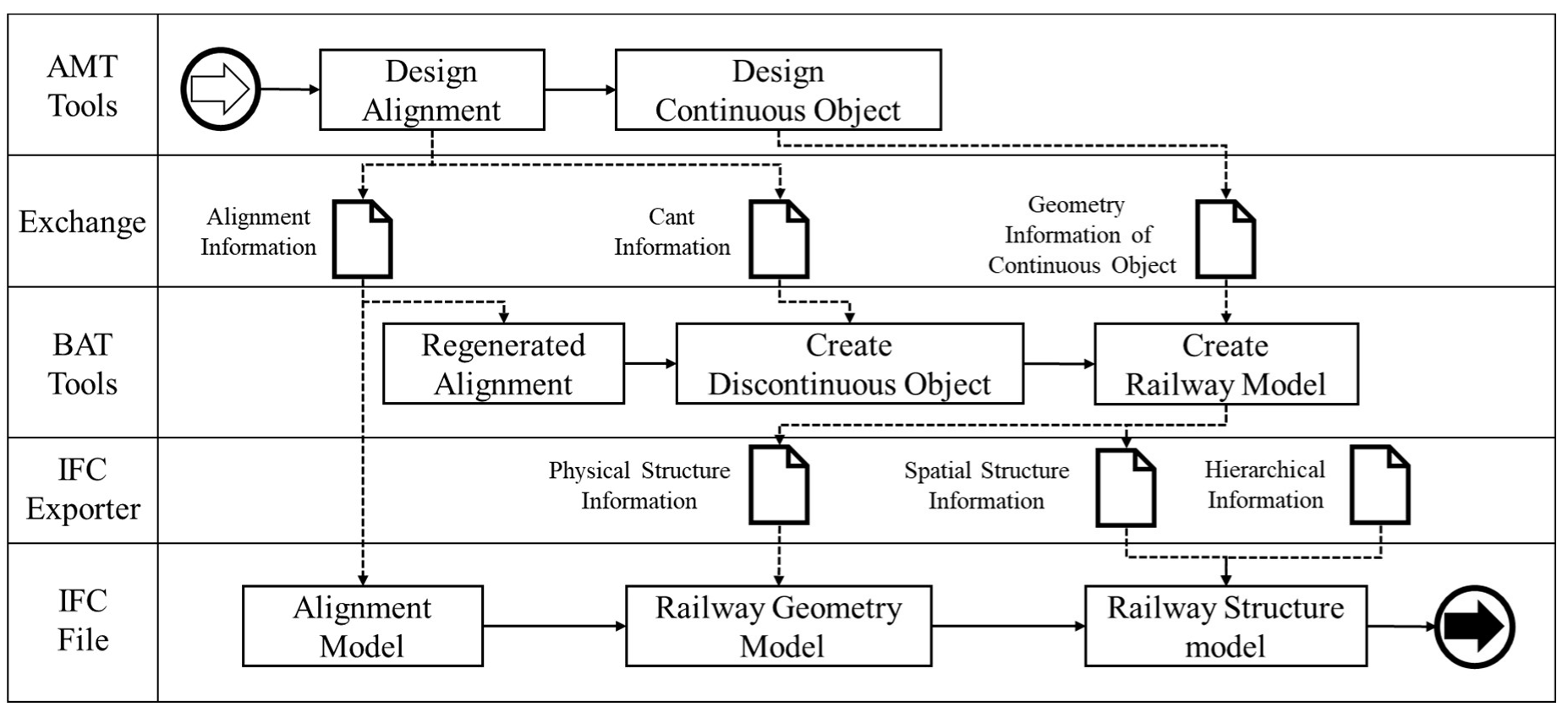
A modeling process that links AMTs and BATs is proposed in this study, as depicted in Figure 2. Both AMT and BAT modeling software is used to create information models that satisfy the BIM concept. An assembly of continuous structures was specified based on 3D alignment, which was regenerated using AMTs. Moreover, it was swept along the alignment, and the crossing points were connected. Continuous structures were converted into solids and transferred to BATs for the integration of track models. Discontinuous structures can be represented using a parametric modeling method based on the linkage between the alignment information created by AMTs [31]. According to this method, the alignment and its attributes are utilized as central media for information linkage between the different software. This is because the alignment plays the role of a baseline, which is the basis of railway track creation. This is also because discreteness is easier to compare against that of the other objects. Discretization is necessary because BIM tools have limitations in representing 3D alignment equations including railway-alignment design parameters exclusively. Therefore, a discretization of alignment was employed for re-arranging discontinuous objects. A non-uniform rational basis splines (NURBS) curve creation method [32] was used in this study to recreate the railway alignment with BATs using the discretization points created with AMTs. As this method does not require generalized equations for the creation of the alignment, the discretization points were used as control points of the NURBS curves.
3.2. Representation of Discontinuous Railway Track Structures
The creation of shapes and attributes of discontinuous objects is an important step. The methodology depicted in Figure 3 was used to represent discontinuous structures. First, discontinuous objects that were to be arranged along the recreated railway alignment were modeled using BATs. The alignment was regenerated by applying BATs to the alignment information, which was generated using AMTs; the locations of the discontinuous objects were then calculated.
L(t,i), which is the rule for correctly placing discontinuous objects, is defined in Equation (1).
where is the conditional function for placing a discontinuous object at point along the alignment, and holds; denotes a specific point that represents object ; and indicates a mapping process. represents the rotation condition of object at point . The rotation condition is required for placing discontinuous objects perpendicular to the direction of the alignment and has an equivalent operational relationship with . The object rotation vector can be expressed using Equation (2).
where , , and represent rotation angles (radians) based on the x-, y-, and z-axes, respectively. In this study, the direction of alignment was set to the y-direction, and the direction perpendicular to the geomorphic surfaces was set as the z-direction. Therefore, represents the pitch, the roll, and the yaw. follows the change in alignment in the xz-plane. Thus, can be calculated using Equation (3).
where and holds. is the direction vector at point on the alignment. is the local reference axis of object and is set to the y-axis in this study. is the rotation angle for the slope of the alignment and is calculated using Equation (4).
where holds. has the same meaning as the cant in railway alignment because it represents the rotation value around the direction of the alignment. In other words, this value is calculated using a separate equation depending on the radius of curvature of the alignment. In this study, the value created by the AMT was used for the BAT. The AMT creates a cant value at points where the alignment equation changes, and this value is calculated via a linear function. can be calculated using the cant value, as shown in Equation (5).
where is the cant value of object and can be calculated by Equation (6).
where represents the cant critical point—that is, the point at which the cant change begins in the alignment to which object belongs; in other words, the value of k changes at the point where the alignment equation changes. is the distance between the location of two rails at object . In Equation (6), is the cant value at point that corresponds to object and is the result obtained from the AMT. Expressed differently, is obtained through a transformation formula that calculates values using the distance between the location of the critical point and the location of object .
When railway track information models were created using the above equations, the location and rotation values of the discontinuous structures, such as sleepers, were calculated according to the 3D alignment. The independent shapes of the discontinuous structures can be created to match the railway alignment by applying the calculated values to the structures.
4. Extended IFC-Based Information Model Creation Method
4.1. IFC Extension for Railway Track Object Representation
Information management is an essential aspect to consider when using BIM. The information is stored and managed in different ways because the same information is used for different purposes by the users. In this study, IFC was used to integrate and manage the information similarly. IFC entities for each element are essential for creating IFC-based railway track information models that facilitate interoperability. However, it is difficult to represent railway track elements because IFC4 × 2, which is the latest IFC version, does not contain elements, such as sleepers and ballasts, which are still under development. Therefore, the entities in this study were extended, according to the basic rules of IFC, to represent railway track elements in addition to alignment.
The schema to be applied to railway track information models was extended following the research of Lee et al. [33], who referred to the China Railway BIM Alliance [6] and Korea Rail Network 3Authority (KR) [34]. Figure 4 illustrates the IFC entities extended in this study through EXPRESS-G diagrams. The IFC entities extended for railway track element representation can be primarily classified into physical entities, which contain information regarding track elements, and spatial entities, which contain information regarding space. The physical entities were represented as “IfcTrackElement” under “IfcCivilElement”, which was created for the extension of infrastructure elements in IFC4 × 2; the spatial entities were represented as “IfcTrackStructureElement” under “IfcCivilSpatialStructureElement”. In detail, “IfcTrackFastening”, “IfcTrackBallast”, “IfcTrackSleeper”, “IfcTrackTurnout”, and “IfcTrackRail” were represented as physical entities, indicating fasteners, ballasts, sleepers, turnouts, and rails, respectively. Regarding the attributes of the extended physical entities, “PredefinedType”, which is an attribute to represent materials, and “FunctionType”, which is an attribute to represent shapes, were added.
The spatial entities were extended to “IfcTrack”, which represents the entire section, and “IfcTrackPart”, which represents parts of the section. Representation of the usage purpose, track gauge, and slack from the railway track design parameters as single physical entities is not suitable; therefore, “PredefinedType”, “TrackGauge”, and “Slack” were added as attributes in “IfcTrackPart”, which contains spatial information. Moreover, an enumeration on the type was added for each entity. Table 1 lists the attributes and types of added entities in Figure 4. For example, “IfcTrackBallastTypeEnum” is added to “IfcTrackBallast” so that “CRUSHEDSTONEBALLAST”, “PEBBLEBALLAST”, “SANDBALLAST”, “SLAGBALLAST”, “CONBALLAST”, “USERDEFINED”, and “NOTDEFINED” can be specified.
The alignment elements added in IFC4 × 2 were used for alignment information. These alignment elements represent alignment through “IFCAlignment” and contain “IFCAlignmentCurve” as their internal attribute. “IFCAlignmentCurve” is an entity for representing 3D curves and includes the horizontal alignment “IFCAlignment2DHorizontal” and vertical alignment “IFCAlignment2DVertical” as its attributes. In this study, the connections between spatial entities in the same hierarchy were represented through “IfcRelAggregates”, and the connections between the spatial and physical entities included as spatial entities were represented through “IfcRelContainedInSpatialStructure”. The connections between the spatial or physical entities and the attributes of these entities were represented through “IfcRelDefinesByProperties”.
4.2. Extended IFC-Based Information Model Creation Method
The railway track information models created using the methodology presented in Section 3 include shape and attribute information. However, because BAT software does not support semantic information for railway track elements, we represented railway track elements with semantic information of other existing supported elements using the software. For example, Autodesk Revit does not support modeling of track elements such as sleepers; thus, such elements must be represented through other elements such as structural foundations.
We developed codes to identify the semantic information of different track elements. A classification system predominantly describing the physical entities of tracks was created by referring to the classification systems proposed by Korea Rail Network Authority [34], Uniclass [35], and Omniclass [36]; classification codes for each category were specified. As the scope of this study included railway tracks, classification codes were specified predominantly for the essential track elements. Table 2 presents the categories and classification codes of the classified objects as well as the extended IFC entities for each category.
Classification codes that correspond to the attribute information of element models were added as identifiers so that the semantic information of track elements could be identified during the conversion between information models. For example, BA201 was added to the attribute information of concrete sleepers so that they could be identified as “IfcTrackSleeper” during the conversion to IFC.
One important consideration during the creation of “.ifc” files in the form of IFC physical files (IPF), based on the extended IFC, is model integration derived by reflecting the spatial concepts of the model objects created by AMTs and BATs. Accordingly, a module for creating extended IFC-based information models in the BAT environment, which manages the integrated models, was developed in this study. Figure 5 illustrates the process of creating hierarchical information. For the selection of appropriate IFC entities, the automatic mapping method based on the classification codes, along with a method in which the end-user directly selects the appropriate IFC entities in the user interface (UI)—as depicted in Figure 6a,b—was used. The external reference file created elements for each object of the models; these elements included the attributes of objects and information on the extended IFC entities, which were mapped to be employed during the creation of IPF files alongside the hierarchical information, as depicted in Figure 6c.
The “Export” module largely consisted of the following three processes depicted in Figure 7: (a) extraction of shape, attribute, and alignment information from AMTs and BATs by obtaining coordinate conversion information for object placement as well as management of such information; (b) creation of an external reference file; (c) creation of extended IFC-based IPF files through the external reference file.
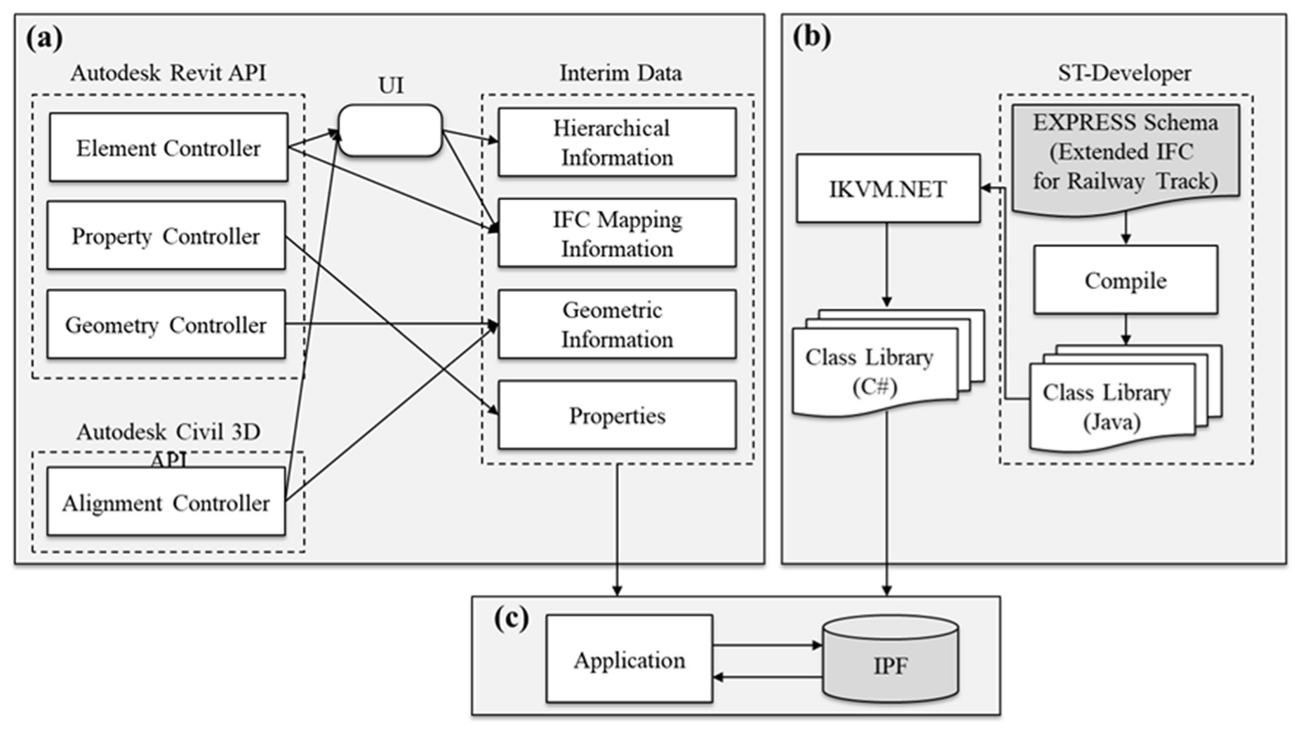
Revit was used as the BAT, and Civil 3D was used as the AMT. The IPF creation module in this study was developed through the compiled C# class library. The EXPRESS code for the aforementioned extended IFC was converted into the Java class library code using ST-Developer [37] of STEP Tools for the creation of this library; the library was converted into the same C# class library code as the Revit application programming interface (API) using IKVM.NET.
The object identifiers contained the shapes and attributes of the objects to create the input files of the IPF creation module. The objects were extracted through the APIs of Revit and Civil 3D and were then stored in the external reference file. The information for shape creation was extracted through the tessellation of solid objects for the identifiers of the surfaces that constitute them, as well as the geometric information of points constituting these surfaces. Extensible markup language (XML) files were used so that the external reference file could include hierarchical information. Single elements of the external reference file were recreated as single elements of the extended IFC. The hierarchical information of the external reference file was used to describe the relationships between the IFC entities using “IfcRelAggregates”, “IfcRelContainedInSpatialStructure”, and “IfcRelDefinesByProperties”.
5. Verification of the Proposed Methodology through the Railway Track Modeling
A railway track information model was created by integrating AMTs and BATs based on the alignments of the actual railway facilities, and a test was conducted pertaining to the generation of an extended IFC-based model. The target for verification was an actual construction site in Osong-gun, Chungcheongbuk-do, South Korea, where a railway test line was being constructed by KR. The line had a total alignment length of 12.989 km; however, a 2-km section was selected as the target for verification because it contained straight lines, transition curves, and circular curves. Cubic parabolas were applied to the transition curves, and the cant was calculated based on a design speed of 250-km/h. Figure 8 presents the process conducted during the case study of the proposed methodology. Autodesk Civil 3D was used as the AMT, and Revit was used as the BMT.
Autodesk Civil 3D [38] was used as the AMT for the creation of the railway alignment, rails, and ballast. The surface model of the terrain was created using Civil 3D based on a digital map of the area, and the railway alignment was conducted by referring to the design documents. 2D cross-sections were created for modeling rails and ballasts and 3D shapes were generated by sweeping them along the alignment. The “property data” function of Civil 3D was used to manage the identifier and cross-section information, which are not included in the basic functions of Civil 3D.
Autodesk Revit [39] was used as the BAT for the creation of discontinuous structures. An object library was created in advance to apply the sleeper objects repeatedly and continuously. The “property sets” function of Revit was used to manage the identifier and cant information, which are not included in the basic functions of the software.
Dynamo Studio is a tool that provides a visual programming environment that can derive results by creating diagrams that include utilization parameters rather than text. Moreover, because it can access the API of Revit, the operation, restriction, and modification of parameters can be easily performed. In this study, Autodesk Dynamo Studio was used to (a) retrieve data from Civil 3D, (b) process these data by applying the algorithm proposed in Section 3, and (c) reflect the processed data in Revit [32]. Figure 9 depicts the algorithm implemented in Dynamo Studio for the shape representation of discontinuous structures.
Figure 10 depicts the model that integrates the ballast and rail models. The sleeper model included in the integrated model was created using the method presented in Section 3.2. An alignment model was created for the 2-km section by referring to the design drawings. An assembly was created for the shapes of continuous structures, and continuous structures were created by placing the assembly according to the alignment model. The generated alignment was discretized at 1-m intervals to link the Revit with the alignment information and converted into 2001 3D point-data. The alignment was regenerated in Revit based on the point-data, and 3400 sleeper locations were created through Dynamo Studio using the methodology described in Section 3.2. As the sleeper objects were placed in the same shape, a pre-prepared shape library was used. The cant-inclusive rotation parameters of sleepers were calculated using location points of the sleepers and alignment information. Figure 10a shows that “x-angle”, “y-angle”, and “z-angle”, which are rotation parameters, were included in the “Dimensions” attribute information of the sleepers, with the values of −0.212°, 13.493°, and 137.056°, respectively. Figure 10b,c show that the z-angle and y-angle, which are the attribute values for the presented rotation, are also reflected in the geometry of the information model, with values of 137.056° and 13.493°, respectively.
The attribute information referred to as “PBScode” was additionally created to identify objects during the creation of the extended IFC-based information model based on the methodology proposed in Section 4.2. Figure 11a–c depict that “sleepers” included “BA202”, whereas “ballasts” and “rails” included “BA301” and “BA101”. The classification codes are shown in Table 1. The attribute information of the extended IFC entities was defined using the developed module described in Section 3.2. For example, “PredefinedType” and “FunctionType” (the attributes in “IfcTrackSleeper” that represent the sleepers) were defined as “WOODENSLEEPER” and “MONOBLOCK”, respectively. “PredefinedType”, “TrackGauge”, and “Slack”, which are the attribute information in “IfcTrackPart”, were defined as “MAINTRACK”, “1500”, and “0”, respectively. The design information not included in the attributes of the extended IFC entities was represented by adding properties. For example, “TechnicalStandard”, representing the design standard, was added to the sleeper model, with its value set to “KS”, as indicated by Figure 11d. Under spatial information, “Track_9-11km” was created as an “IfcTrack” element under “IfcSite”. “Station1” and “Station3”, which are earthwork sections, as well as “Station2”, which is a bridge section, were created as “IfcTrackPart” elements under “Track_9-11”, in accordance with the aims of this study.
Table 3 presents a part of the model created based on the extended IFC using the methodology presented in Section 3. In the case of the “Sleeper-#2195949” object, the physical information was represented using “IfcTrackSleeper(#2195949)”. “PredefinedType” and “FunctionType”, which are attributes of the physical entities, were defined as “WOODENSLEEPER” and “MONOBLOCK”, respectively, as mentioned above. The geometric information of “Sleeper-#2195949” was represented using “IfcProductDefinitionShape(#870446)”. Additionally, “IfcTrackSleeper(#2195949)” was combined with “IfcTrackPart(#2199347)”, which represents “Station1” through “IfcRelContainedInSpatialStructure(#11)”. In this instance, “PredefinedType”, “TrackGauge”, and “Slack”, which are attributes in the spatial entities of “Station1”, were defined as “MAINTRACK”, “1500”, and “0.0”, respectively, as previously mentioned. “#2199347”, which represents “Station1”, was combined with “IfcTrack(#10)”, which represents “Track_9-11km”, using “IfcRelAggregates(#2172040)”. Moreover, “Track_9-11km” was combined with “IfcSite(#2172046)”, which represents the entire space of the information model, using “IfcRelAggregates(#2172039)”. “Identity Data (Type)”, which was integrated in the modeling process, was represented as “IfcPropertySet(#2172105)” and was combined with “IfcTrackSleeper(#2195949)” using “IfcRelDefinesByProperties(#542197)”. “Identity Data (Type)”—an attribute set—was connected to “IfcPropertySingleValue(#2199441)”, which represents the attribute “Type”, and its value was created as “Wood”. Moreover, the alignment information was represented using “IFCAligment(#2785901)”. “IFCAligment2DHorizontal(#2785954)”, which is the horizontal alignment, was combined with “IFCAligment2DVertical(#2786105)”, which is the vertical alignment, using “IFCAligmentCurve(#2785910)”. Figure 12 depicts these contents in a diagram. A generic AP checker provided by ST-Developer [37] confirmed the validity of the proposed extended IFC-based railway track IPF’s syntax and its compatibility with the developed EXPRESS.
Figure 13 provides the geometric information of the railway tracks and the attribute information of “Sleeper-#2195949”, which was represented in the Solibri Model Checker upon conversion of the extended IFC-based model. As extended IFC-based models cannot be entered into the existing software, physical entities were converted into “IfcBuildingElementProxy” and spatial entities into “IfcBuilding” and “IfcBuildingStory”. As previously mentioned, “Station1”, “Station2”, and “Station3” were included under “Track_9-11km”, which represents spatial information, as shown on the left-hand side of Figure 13. Furthermore, “KS”, which is the value of the “TechnicalStandard” represented using “Property”, is depicted in the lower right-hand corner of Figure 13. However, it was found that information was lost because the semantic information of the railway track elements could not be identified, and “PredefinedType” and “FunctionType”—which are attribute information belonging to “IfcTrackSleeper”—could not be represented in the existing IFC4.
6. Discussion and Conclusions
The application of BIM to alignment-based infrastructure facilities, such as roads and railways, is being increasingly explored. However, BIM software is optimized to represent floor-based vertical buildings. In the case of railway tracks, the structures must be placed along the 3D alignment, and each element must be independently represented to facilitate information management. AMTs manage separate objects as a single unified object along the alignment; thus, they present severe limitations regarding the accurate representation of each object. Therefore, a single software cannot create all element models of different infrastructure. A modeling process employing multiple modeling software should be integrated to represent railway tracks; the interoperability of information between the employed software must be secured.
In this study, a method for creating extended IFC-based models was proposed to apply BIM to railway tracks and manage information based on 3D alignment. First, continuous structures (rails and ballasts) and discontinuous structures (sleepers, fasteners, and joints) that reflect the cant were created through the linkage of discretized alignment information. Second, classification systems for each element were created. The elements such as “IfcTrack” and “IfcTracksleeper” were newly defined according to the classification systems. They include the expression of railway tracks and the properties of the structures thereof. Third, element models were matched to extended IFC entities using classification codes as identifiers. Finally, extended IFC-based information models were created by recognizing objects through classification codes, UI, and spatial information. The proposed methodology enables the actual railway track to behave as an extended IFC-based information model. The proposed method was verified upon validating the IPF, based on the extended IFCs.
The proposed methodology can (a) employ functions of the existing software, (b) facilitate the creation of information models of railway tracks by linking alignment information, and (c) convert them into extended IFC schema-based information models. Its implementation can reduce the modeling time required for the creation of railway track information models. Other functions of the existing software can also be employed because the connecting AMT and BAT software is executed using the 3D alignment information. It is expected that the proposed methodology can also be effectively applied to create information models of other alignment-based infrastructure, such as roads. Moreover, the method enables automatic identification of components to IFC elements regardless of the type of structure. One benefit of the proposed method is that it can facilitate the development of a model of infrastructure other than railway tracks in the future.
The traditional method of setting the actual location employs a local coordinate system and a reference point containing global coordinate information. The proposed methodology facilitates the creation of a model according to the actual location information because of alignment information. It is expected that the created models can be integrated with the information models of other structures. For example, it is expected that they can be linked with terrain models created from the actual terrain data or other structural models, such as railway bridges.
Future research should focus on the ways in which the proposed methodology can support BIM of railways. First, the functions of the data schema for railway track representation must be proven. The railway structures have a long-life cycle with various types of data. Therefore, the generated model should include various types of information using the life cycle.
Second, constraints to structures need to be further researched. The constraints are applicable between the lower and upper objects. These constraints can enable determination of the position between ballasts and sleepers and between rail and sleepers. This research can help designers efficiently create models because a change in the lower object leads to a change in the upper object automatically.
Third, the process of modeling other structures should be further researched. The proposed methodology expresses only basic railway track elements. The process is especially significant for structures created under specific conditions such as switches. The shape and placement of other elements require the development of a parametric rule.
Finally, a methodology is required to apply the information model for railway tasks. The information model will contribute to improving the efficiency of maintenance. The sleepers can clearly express their information via the discussed methodologies. Therefore, the individual management of sleepers is possible.
Author Contributions
Conceptualization, methodology, T.H.K. and S.I.P.; validation, Y.-H.J.; supervision, S.-H.L.; All authors have read and agreed to the published version of the manuscript.
Funding
This work is supported by the Korea Agency for Infrastructure Technology Advancement (KAIA) grant funded by the Ministry of Land, Infrastructure and Transport (Grant 20RBIM-B158185-01).
Conflicts of Interest
The authors declare no conflict of interest.
References
- Zhou, C.; Wang, W. Highway bridge construction process simulation base on 4D visualization. In Asphalt Material Characterization, Accelerated Testing, and Highway Management: Selected Papers, Proceedings of 2009 GeoHunan International Conference, Changsha, Hunan, China, 3–6 August 2009; ASCE: Reston, VA, USA, 2009; pp. 138–145. [Google Scholar] [CrossRef]
- Kim, H.; Orr, K.; Shen, Z.; Moon, H.; Ju, K.; Choi, W. Highway alignment construction comparison using object-oriented 3D visualization modeling. J. Constr. Eng. Manag. 2014, 140, 05014008. [Google Scholar] [CrossRef]
- Vitásek, S.; Matějka, P. Utilization of BIM for automation of quantity takeoffs and cost estimation in transport infrastructure construction projects in the Czech Republic. In Proceedings of the IOP Conference Series: Materials Science and Engineering, Prague, Czech Republic, 21–22 September 2017; IOP Publishing: Bristol, England, 1874; p. 012110. [Google Scholar] [CrossRef] [Green Version]
- Jones, S.; Laquidara-Carr, D.; Lorenz, A.; Buckley, B.; Barnett, S. The Business Value of BIM for Infrastructure 2017; Dodge Data & Analytics: Bedford, MA, USA, 2017. [Google Scholar]
- Qatar Rail. Qatar Rail Building Information Modelling Guidelines-MCR Overview; Qatar Rail: Doha, Qatar, 2011. [Google Scholar]
- China Railway BIM Alliance. Alliance (CRBIM) (2015) Railway BIM Data Standard Version 1.0; China Railway BIM Alliance: Beijing, China, 2013. [Google Scholar]
- MTR. Hong Kong Metro MTR Sustainability Report 2016; MTR: New Kowloon, Hong Kong, China, 2016. [Google Scholar]
- Froese, T. Future directions for IFC-based interoperability. J. Inf. Technol. Constr. 2003, 8, 231–246. [Google Scholar] [CrossRef]
- Venugopal, M.; Eastman, C.M.; Sacks, R.; Teizer, J. Semantics of model views for information exchanges using the industry foundation class schema. Adv. Eng. Inform. 2012, 26, 411–428. [Google Scholar] [CrossRef]
- Costin, A.; Adibfar, A.; Hu, H.; Chen, S.S. Building Information Modeling (BIM) for transportation infrastructure–literature review, applications, challenges, and recommendations. Automat. Constr. 2018, 94, 257–281. [Google Scholar] [CrossRef]
- Sampaio, A.N.Z. Geometric modeling of box girder deck for integrated bridge graphical system. Automat. Constr. 2003, 12, 55–66. [Google Scholar] [CrossRef]
- Ji, Y.; Borrmann, A.; Obergrieβer, M. Toward the exchange of parametric bridge models using a neutral data format. In Proceedings of the International Workshop on Computing in Civil Engineering, Miami, FL, USA, 19–22 June 2011; ASCE: Reston, VA, USA, 2011; pp. 528–535. [Google Scholar] [CrossRef] [Green Version]
- Amann, J.; Singer, D.; Borrmann, A. Extension of the upcoming IFC alignment standard with cross sections for road design. In Proceedings of the ICCBEI 2015, Tokyo, Japan, 22–24 April 2015; AGCEI: Tokyo, Japan, 2015; pp. 22–24. [Google Scholar]
- Lee, G.; Sack, R.; Eastman, C.M. Specifying parametric building object behavior (BOB) for a building information modeling system. Automat. Constr. 2006, 15, 758–776. [Google Scholar] [CrossRef]
- Neves, J.; Sampaio, Z.; Vilela, M. A Case study of BIM implementation in rail track rehabilitation. Infrastructures 2019, 4, 8. [Google Scholar] [CrossRef] [Green Version]
- Kenley, R.; Harfield, T.; Behnam, A. BIM interoperability limitations: Australian and Malaysian rail projects. In Proceedings of the 4th International Building Control Conference 2016, Kuala Lumpur, Malaysia, 7–8 March 2016; EDP Sciences: Les Ulis, France, 2016; p. 00102. [Google Scholar] [CrossRef] [Green Version]
- Jeong, Y.-S.; Eastman, C.; Sacks, R.; Kaner, I. Benchmark tests for BIM data exchanges of precast concrete. Automat. Constr. 2009, 18, 469–484. [Google Scholar] [CrossRef]
- Nour, M. Performance of different (BIM/IFC) exchange formats within private collaborative workspace for collaborative work. J. Inf. Technol. Constr. 2009, 14, 736–752. [Google Scholar] [CrossRef]
- Venugopal, M.; Eastman, C.M.; Teizer, J. An ontology-based analysis of the industry foundation class schema for building information model exchanges. Adv. Eng. Inform. 2015, 29, 940–957. [Google Scholar] [CrossRef] [Green Version]
- Steuer, H.; Flurl, M.; Donaubauer, A.; Mundani, R.-P.; Kolbe, T.H.; Rank, E. Collaborative planning of inner-city-railway-tracks: A generic description of the geographic context and its dynamic integration in a collaborative multi-scale geometry modelling environment. Adv. Eng. Inform. 2014, 28, 261–271. [Google Scholar] [CrossRef]
- ISO-TC59/SC13. ISO 16739-1:2018 Industry Foundation Classes (IFC) for Data Sharing in the Construction and Facility Management Industries—Part 1: Data Schema; ISO: Geneva, Switzerland, 2014. [Google Scholar] [CrossRef]
- Yabuki, N.; Lebegue, E.; Gual, J.; Shitani, T.; Zhantao, L. International collaboration for developing the bridge product model IFC-Bridge. In Proceedings of the Joint International Conference on Computing and Decision Making in Civil and Building Engineering, Montreal, QC, Canada, 14–16 June 2006; EG-ICE: Berlin, Germany, 2006. [Google Scholar] [CrossRef] [Green Version]
- Amann, J.; Flurl, M.; Jubierre, J.; Borrmann, A. An approach to describe arbitrary transition curves in an IFC-based alignment product data model. In Proceedings of the 2014 International Conference on Computing in Civil and Building Engineering, Orlando, FL, USA, 23–25 June 2014; ASCE: Reston, VA, USA, 2014; pp. 933–941. [Google Scholar] [CrossRef] [Green Version]
- Chipman, T.; Costin, A.; Eastman, C.; Grant, R.; Liebich, T.; Smith, D.; Yang, D. Bridge Information Modeling Standardization–Report Introduction; National Institute of Building Sciences: Washington, DC, USA, 2016. [Google Scholar]
- Park, S.I.; Park, J.; Kim, B.-G.; Lee, S.-H. Improving Applicability for Information Model of an IFC-Based Steel Bridge in the Design Phase Using Functional Meanings of Bridge Components. Appl. Sci. 2018, 8, 2531. [Google Scholar] [CrossRef] [Green Version]
- buildingSMART. IFC Overview Summary, buildingSMART International. Available online: https://standards.buildingsmart.org/IFC/DEV/IFC4_2/FINAL/HTML/ (accessed on 14 May 2020).
- Lee, S.-H.; Park, S.I.; Kwon, T.H.; Seo, K.-W. Civil infrastructure information modeling method based on extended IFC entities using BIM authoring software. J. Comput. Struct. Eng. Inst. Korea 2017, 30, 77–86. [Google Scholar] [CrossRef]
- Gao, G.; Liu, Y.-S.; Wu, J.-X.; Gu, M.; Yang, X.-K.; Li, H.-L. IFC Railway: A Semantic and Geometric Modeling Approach for Railways based on IFC. In Proceedings of the 16th International Conference on Computing in Civil and Building Engineering, Osaka, Japan, 6–8 July 2016; ISCCBE: Osaka, Japan, 2016; pp. 1188–1195. [Google Scholar]
- Huang, S.-F.; Chen, C.-S.; Dzeng, R.-J. Design of track alignment using building information modeling. J. Transport. Eng. 2011, 137, 823–830. [Google Scholar] [CrossRef]
- Autodesk. User’s Guide, Autodesk; Autodesk: San Rafael, CA, USA, 1982. [Google Scholar]
- Kwon, T.H.; Park, S.I.; Shin, M.H.; Lee, S.-H. Information Modeling of Railway Track using Information Iinkage of Railway Alignment and Alignment-based Objects. J. Comput. Struct. Eng. Inst. Korea 2017, 30, 507–514. [Google Scholar] [CrossRef]
- JEZYK, M. The Dynamo Primer; Autodesk: San Rafael, CA, USA, 1982. [Google Scholar]
- Lee, S.-H.; Park, S.I.; Park, J. Development of an IFC-based data schema for the design information representation of the NATM tunnel. KSCE J. Civ. Eng. 2016, 20, 2112–2123. [Google Scholar] [CrossRef]
- Korea Rail Network Authority. Procedures of Project Management for Railway; Korea Rail Network Authority: Daejeon, Korea, 1963; Volume 34. [Google Scholar]
- Crawford, M.J.; Cann, J.; O’Leary, R. Uniclass: Unified Classification for the Construction Industry; RIBA: London, UK, 1997. [Google Scholar]
- OmniClass, C. Introduction and User’s Guide; The Construction Specification Institute: Alexandria, Egypt, 2006. [Google Scholar]
- STEP Tools. ST-Developer online Manuals; STEP Tools: New York, NY, USA, 1991–2007. [Google Scholar]
- Autodesk. Autodesk Civil 3D 2020. Available online: https://help.autodesk.com/view/CIV3D/2020/ENU/ (accessed on 14 May 2020).
- Autodesk. Autodesk Revit 2020. Available online: https://help.autodesk.com/view/RVT/2020/ENU/ (accessed on 14 May 2020).
Figure 1.
Software representation of railway track: (a) A railway model based on building information modeling authoring tools (BATs); (b) a railway model based on alignment-centered modeling tools (AMTs).
Figure 1.
Software representation of railway track: (a) A railway model based on building information modeling authoring tools (BATs); (b) a railway model based on alignment-centered modeling tools (AMTs).

Figure 2.
Process of railway track modeling using software linkage. AMT: Alignment-centered modeling tools; BAT: BIM authoring tools; IFC: STEP Tools; IFC: industry foundation class.
Figure 2.
Process of railway track modeling using software linkage. AMT: Alignment-centered modeling tools; BAT: BIM authoring tools; IFC: STEP Tools; IFC: industry foundation class.

Figure 3.
Algorithm for shape representation of discontinuous structures.

Figure 4.
Extended IFC entities for railway tracks: (a) Extension of physical entities; (b) extension of spatial entities.
Figure 4.
Extended IFC entities for railway tracks: (a) Extension of physical entities; (b) extension of spatial entities.

Figure 5.
Process for creating hierarchical information using Autodesk Revit API.

Figure 6.
User interfaces for management: (a) UI for managing spatial information of each object; (b) UI for managing physical information of each object; (c) Tree view for managing hierarchical information.
Figure 6.
User interfaces for management: (a) UI for managing spatial information of each object; (b) UI for managing physical information of each object; (c) Tree view for managing hierarchical information.

Figure 7.
Extended IFC-based information modeling processes for alignment-based structures. Panels (a–c) illustrate different processes. API: application programming interface; IPF: IFC physical files; ST: STEP Tools; UI: user interface.
Figure 7.
Extended IFC-based information modeling processes for alignment-based structures. Panels (a–c) illustrate different processes. API: application programming interface; IPF: IFC physical files; ST: STEP Tools; UI: user interface.

Figure 8.
Process for followed for case study conducted at the: Railway in Osong-gun, located in South Korea.
Figure 8.
Process for followed for case study conducted at the: Railway in Osong-gun, located in South Korea.

Figure 9.
Algorithm for shape representation of discontinuous objects in Autodesk Dynamo Studio.

Figure 10.
An example of the information model of discontinuous objects: (a) Properties of a sleeper; (b) model in the xy-plane; and (c) model in the xz-plane.
Figure 10.
An example of the information model of discontinuous objects: (a) Properties of a sleeper; (b) model in the xy-plane; and (c) model in the xz-plane.

Figure 11.
Railway track model in Autodesk Revit. (a) PBScode of sleeper; (b) PBScode of rail; (c) PBScode of ballast; and (d) An example of the information of sleeper.
Figure 11.
Railway track model in Autodesk Revit. (a) PBScode of sleeper; (b) PBScode of rail; (c) PBScode of ballast; and (d) An example of the information of sleeper.

Figure 12.
EXPRESS-G of the IFC-based railway track model.

Figure 13.
IFC4-based model in Solibri Model Checker.


Table 1.
Attributes and types of extended physical entities.
| Entity | Attribute | Type | Enumeration |
|---|---|---|---|
| IfcTrackRail | Predefined Type | IfcTrackRail TypeEnum | MAINRAIL, GUARDRAIL, LEADRAIL, TONGUERAIL, CROSSING, USERDEFINED, NOTDEFINED |
| IfcTrack Sleeper | Predefined Type | IfcTrackSleeper TypeEnum | WOODENSLEEPER, CONSLEEPER, USERDEFINED, NOTDEFINED |
| Function Type | IfcTrackSleeperFunction TypeEnum | MONOBLOCK, BIBLOCK, USERDEFINED, NOTDEFINED | |
| IfcTrack Fastening | Predefined Type | IfcTrackFastening TypeEnum | ELASTICRAILFASTENING, RIGIDRAILFASTENING, USERDEFINED, NOTDEFINED |
| Function Type | IfcTrackFasteningStructure TypeEnum | SEPARATEDRAILFASTENING, SEMISEPARATEDRAILFASTENING, NONSEPARATEDRAILFASTENING, USERDEFINED, NOTDEFINED | |
| IfcTrack Ballast | Predefined Type | IfcTrackBallast TypeEnum | CRUSHEDSTONEBALLAST, PEBBLEBALLAST, SANDBALLAST, SLAGBALLAST, CONBALLAST, USERDEFINED, NOTDEFINED |
| IfcTrack Turnout | Predefined Type | IfcTrackTurnout TypeEnum | LEFTHANDTURNOUT, RIGHTHANDTURNOUT, SYMMETRICALTURNOUT, SLIPTOURNOUT, SCISSORSCROSSING, DIAMONDCROSSING, COMBINATIONOFSLIPTURNOUTANDSCISSORSCROSSING, USERDEFINED, NOTDEFINED |
| IfcTrack (space) | Predefined Type | IfcTrack TypeEnum | PARTIAL, SINGLE, COMPLEX, USERDEFINED, NOTDEFINED |
| IfcTrackPart (space) | Predefined Type | IfcTrackPart TypeEnum | MAINTRACK, STATIONTRACK, BRIDGETRACK, TUNNELTRACK, USERDEFINED, NOTDEFINED |
| Track Gauge | IfcLengthMeasure | ||
| Slack | IfcLengthMeasure |
Table 2.
Classification system for railway tracks.
| Category | Code | Object | Extended IfcEntity |
|---|---|---|---|
| Common | BA000 | Common | IfcCivilElementProxy |
| Rail | BA101 | Rail | IfcTrackRail |
| Sleeper | BA201 | Concrete sleeper | IfcTrackSleeper |
| BA202 | Wood sleeper | IfcTrackSleeper | |
| Ballast | BA301 | Gravel ballast | IfcTrackBallast |
| BA302 | Concrete ballast | IfcTrackBallast | |
| Facilities | BA400 | Common | IfcCivilElementProxy |
| BA401 | Fish plate | IfcTrackFastening | |
| BA402 | Expansion joint | IfcTrackFastening | |
| BA403 | Insulated rail | IfcTrackRail | |
| BA404 | Compromised rail | IfcTrackRail | |
| Turnout | BC101 | Turnout | IfcTrackTurnout |
Table 3.
IPF of the IFC-based railway track model.
| Object | IFC Model Data |
|---|---|
| Sleeper- #2195949 | ⋯ |
| #10=IFCTRACK(‘g12xD33Df0OSVcfMeX1IPA’,$,‘Track_9-11km’,‘’,‘’,$,$,‘’,$,.COMPLEX.); | |
| #11=IFCRELCONTAINEDINSPATIALSTRUCTURE(‘8UBCh9ZZt06yQPuB+G0IRg’,#1419392,‘Station1’,$,(#566038,#566039,#1419393,#1419394,#2195945,⋯,#2195949, #2785901,⋯),#2199347); | |
| #870446=IFCPRODUCTDEFINITIONSHAPE($,$,(#873860)); | |
| #2172039=IFCRELAGGREGATES(‘lEfakPELQkqvscvYEO+o/A’,#1419392,‘Site’,$,#2172046,(#10)); | |
| #2172040=IFCRELAGGREGATES(‘l5ps4odfwqOz2oxFRsAuzg’,#1419392,‘Track_9-11km’,$,#10,(#2199347,#2199348,#2199349)); | |
| #2172046=IFCSITE(‘LF48Xx6oO0+esS//+ImT0Q’,#1419392,‘Site’,‘’,‘’,#566044,$,‘’,$,(42,21,31,181945),(−71,−3,−24,−263305),0.0,‘’,$); | |
| #2199347=IFCTRACKPART(‘WSunyN1gV0mnF8dyoJ6mVg’,$,‘Station1’,‘’,‘’,$,$,‘’,$,$,1500,0.0); | |
| #2195949=IFCTRACKSLEEPER(‘Rsk2ej62mUyH5bA/Pv1eRg’,#1419392,‘sleeper’,‘’,‘’,#566044,#870446,‘’,$,$); | |
| #542197=IFCRELDEFINESBYPROPERTIES(‘6OTRuJsNlUG31kjlq50Tmw’,#1419392,$,$,(#2195949),#2172105); | |
| #2172105=IFCPROPERTYSET(‘nQdRHi05DU+YTmXxLT0ryA’,#1419392,‘Identity Data (Type)’,$,(2199434,#2199435,#2199436,#2199437,#2199438,#2199439,#2199440,#2199441)); | |
| #2199441=IFCPROPERTYSINGLEVALUE(‘Type’,$,IFCTEXT(‘Wood’),$); | |
| #2785901=IFCALIGNMENT(‘WGzzDEO8XUOCxMz4t49qkQ’,$,‘Alignment - (9)’,‘’,‘’,$,$,$,#2785910,.NOTDEFINED.) | |
| #2785910=IFCALIGNMENTCURVE(#2785954,#2786105, $) | |
| ⋯ |
© 2020 by the authors. Licensee MDPI, Basel, Switzerland. This article is an open access article distributed under the terms and conditions of the Creative Commons Attribution (CC BY) license (http://creativecommons.org/licenses/by/4.0/).
Share and Cite
MDPI and ACS Style
Kwon, T.H.; Park, S.I.; Jang, Y.-H.; Lee, S.-H. Design of Railway Track Model with Three-Dimensional Alignment Based on Extended Industry Foundation Classes. Appl. Sci. 2020, 10, 3649. https://0-doi-org.brum.beds.ac.uk/10.3390/app10103649
AMA Style
Kwon TH, Park SI, Jang Y-H, Lee S-H. Design of Railway Track Model with Three-Dimensional Alignment Based on Extended Industry Foundation Classes. Applied Sciences. 2020; 10(10):3649. https://0-doi-org.brum.beds.ac.uk/10.3390/app10103649
Chicago/Turabian StyleKwon, Tae Ho, Sang I. Park, Young-Hoon Jang, and Sang-Ho Lee. 2020. "Design of Railway Track Model with Three-Dimensional Alignment Based on Extended Industry Foundation Classes" Applied Sciences 10, no. 10: 3649. https://0-doi-org.brum.beds.ac.uk/10.3390/app10103649
Note that from the first issue of 2016, this journal uses article numbers instead of page numbers. See further details here.