Article

Rectangular Closed Double Magnetic Circuit Offering Ultra-Long Stroke for Ultra-Low-Frequency Vibration Exciter

1
Center of Ultra-Precision Optoelectronic Instrument engineering, Harbin Institute of Technology, Harbin 150080, China
2
Key Lab of Ultra-precision Intelligent Instrumentation (Harbin Institute of Technology), Ministry of Industry and Information Technology, Harbin 150080, China
*
Author to whom correspondence should be addressed.
Submission received: 21 July 2020 / Revised: 17 August 2020 / Accepted: 1 September 2020 / Published: 3 September 2020
(This article belongs to the Section Applied Physics General)

Abstract

:
High-performance magnetic circuit offering uniform magnetic flux density (MFD) along ultra-long stroke is the key to develop a vibration exciter for ultra-low-frequency (ULF) vibration calibration. In this paper, a rectangular closed double magnetic circuit (RCDMC) offering ultra-long stroke up to 1.2 m is modeled and optimized. In order to overcome the modeling difficulty arising from the long stroke, a high-accuracy theoretical model is established taking advantage of the structural symmetry of the RCDMC through lumped parameter magnetic equivalent circuit method. Matrix equations are derived based on Kirchhoff’s law and solved by iteration calculation to deal with the strong nonlinear characteristics of the yoke material. The deviations between the model and finite element method (FEM) analysis results are less than 1% for non-saturated yokes and ~10% for saturated yokes. Theoretically, an MFD up to 122 mT and an acceleration waveform harmonic distortion (AWHD) as low as 0.45% are achieved through model-based optimization. Experiments are carried out using an RCDMC prototype assembled in a horizontal vibration exciter. The experimental results show that an MFD of 102 mT and an AWHD of 0.27% along 1.2 m stroke are achieved, making the proposed RCDMC a solution for ULF vibration exciter.

1. Introduction

Calibration of ultra-low-frequency (ULF) (below 0.1 Hz) vibration is urgently needed in various fields including aerospace engineering, precision machining and manufacturing, structural dynamic analysis, earthquake forecast, sea-wave monitoring and warning, mineral exploration, etc. [1,2,3]. However, it is quite difficult due to a variety of reasons, especially the lack of the high-precision vibration exciter that can generate ULF standard vibration with very low acceleration waveform harmonic distortion (AWHD) [4]. For the development of the high-precision low-frequency electromagnetic vibration exciter, high-performance magnetic circuit offering uniform magnetic flux density (MFD) along the long stroke (above 1 m) is essential [5], which is also the technological know-how of a couple of vibration exciter manufacturers in the world. Although the performance advantages of closed double magnetic circuits (CDMCs) have been demonstrated [6,7,8], on the one hand, it places extremely high demands on permanent magnet (PM) material and the precision of machining and assembly, and on the other hand, theoretical modeling for the structure design is demanding.
Compared to short stroke magnetic circuits, great difficulty in theoretical modeling is presented in developing an ultra-long stroke CDMC for an ULF metrological vibration exciter. The reluctance caused by the yokes, which is ignorable in short-stroke magnetic circuits [9,10,11,12], becomes a key factor limiting the uniformity of MFD distribution. The MFD curve which is approximately a straight line in short-stroke magnetic circuits is of an obvious basin shape. On the other hand, to achieve high and uniform MFD along long stroke and low acceleration waveform harmonic distortion, the requirement for modeling precision is much higher than normal electrodynamic actuators. Currently, there is very little literature on high-accuracy theoretical models for long-stroke CDMCs. He et al. proposed a lumped parameter magnetic equivalent circuit (LPMEC) model [7] to analyze a cylindrical CDMC based on Kirchhoff’s law and the superposition theorem. As the reluctance in the yoke is difficult to express, and the MFD varies along the radial direction, the established model is limited. Meanwhile, the strong nonlinear characteristics of yokes and magnetic flux leakage in the CDMC bring extra difficulty in solving model equations [10,13,14,15,16,17]. Therefore, only qualitative conclusions rather than precise quantitative parameters or characteristic curves were obtained.
In this paper, a patented rectangular closed double magnetic circuit (RCDMC) [18,19] offering ultra-long stroke for ULF vibration exciter is proposed. A high-accuracy theoretical modeling method is proposed through the LPMEC method taking advantage of structural symmetry. The model is solved by iteration calculation and verified through comparison with the finite-element method (FEM). Model-based optimization and experimental verification are carried out. Finally, a vibration exciter with a stroke up to 1.2 m is realized.

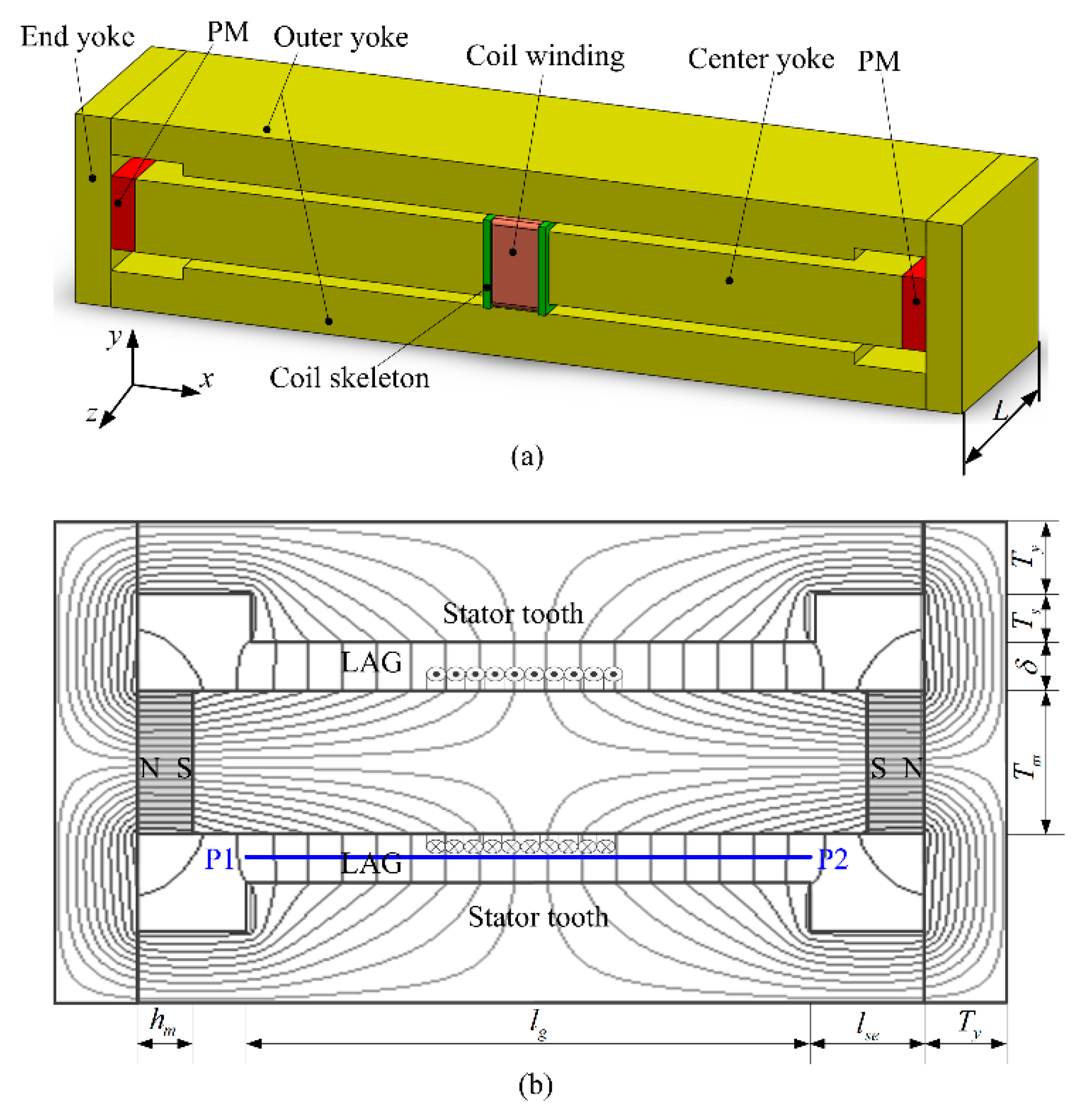
2. Principle of RCDMC

As shown in Figure 1, the proposed structure of RCDMC consists of two PMs, one center yoke, two outer yokes and two end yokes. The two PMs are magnetized horizontally in opposite directions, thus the magnetic poles of the two PMs in contact with the center yoke are of the same polarity, which is the south pole in Figure 1. In this way, in the proposed RCDMC there are only one pole pair (two PMs) and one stator tooth pair, which are protrusive in the middle of outer yokes. Two long air gaps (LAGs) are formed between the stator tooth pair and the center yoke. In this structure, magnetic flux lines can form a set of closed loops through the center yoke, air gaps, outer yokes and one end yoke. Uniform MFD distribution is therefore formed in the two LAGs, along which the Al2O3 ceramic coil skeleton with coil winding wrapped can be moved with driving current flowing in coil winding.

3. Theoretical Modeling by LPMEC Method
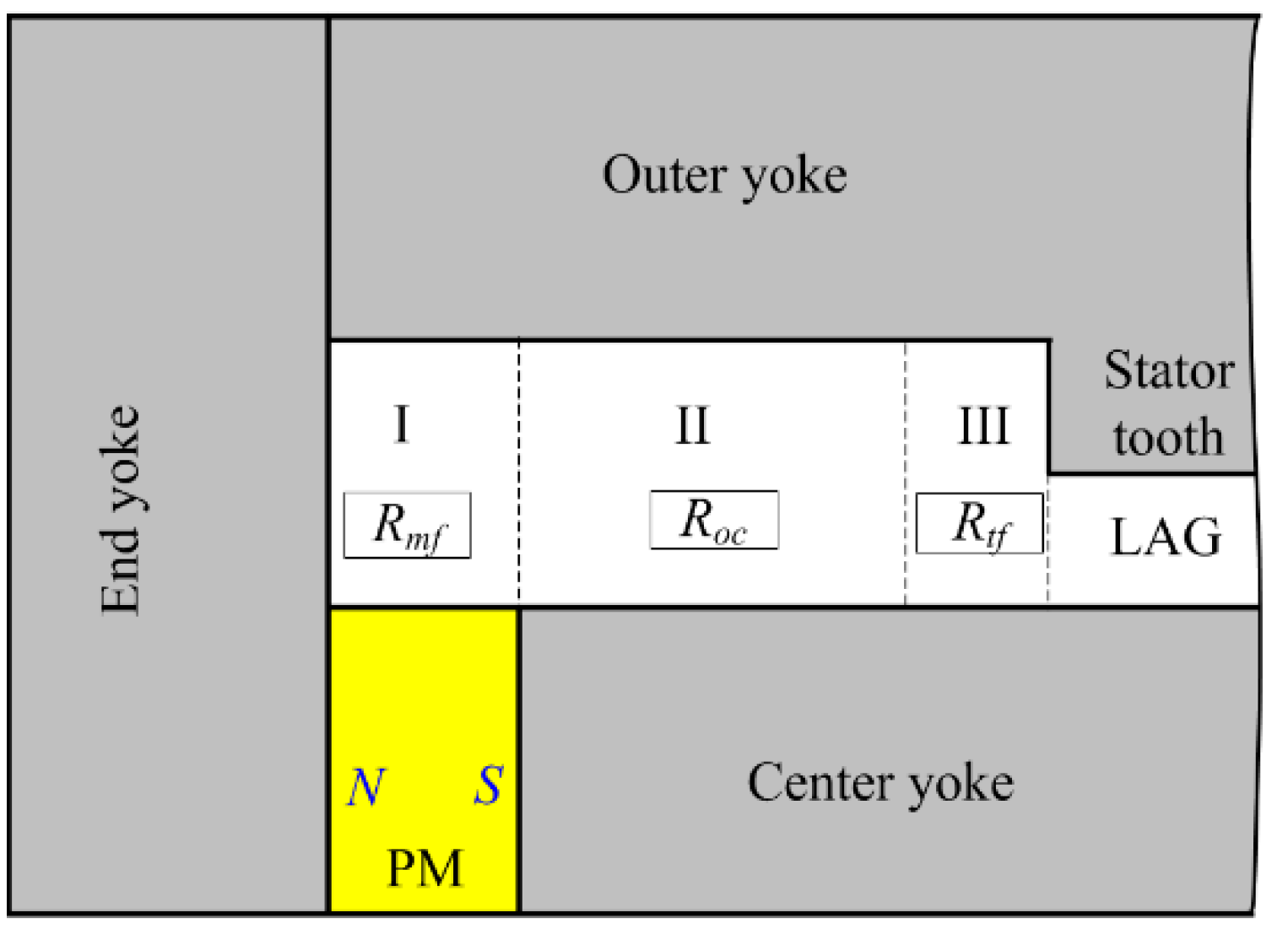
In the 2D planar model as shown in Figure 1b, only the upper half loop is theoretically modeled taking advantage of its symmetry. The RCDMC is modeled assuming that there is no saturation occurring in the yokes, and the magnetic flux leakage outside the RCDMC is ignored. This assumption is proved reasonable by later optimization design results.

3.1. LPMEC Model

According to existing research, the magnetic flux leakage inside a CDMC is inevitable, cannot be ignored and is difficult to be quantitatively analyzed [9,13]. In this research, an LPMEC model without considering the magnetic flux leakage is first established, as shown in Figure 2. The long air gap is divided into N equal segments along the axial direction, the center yoke and outer yoke are respectively divided into N + 1 segments along the axial direction: N − 1 equal segments in the middle and two segments left at the two ends.
The magnetic flux leakage is divided into three parts, as shown in Figure 3. The reluctance of part I, Rmf, corresponds to PM leakage flux; the reluctance of part II, Roc, corresponds to outer-to-center-yoke leakage flux; the reluctance of part III, Rtf, corresponds to tooth-to-center-yoke leakage flux.
The Rmf is obtained by modeling magnetic flux flowing in the air gap, as depicted in Figure 4. For the case of hm < Ts + δ, as shown in Figure 4a, the magnetic flux leakage Rmf is modeled with a circular-arc model, the whole magnetic flux leakage by PM, ϕ m l , is an integral of differential flux flowing through differential width dx, and can be expressed as
ϕ m l = 0 h m F ( x ) R ( x ) = 0 h m 2 μ 0 B r L π μ m d x = 2 μ 0 B r L h m π μ m
where F(x) is the magneto-motive force and is expressed as F(x) = Brx / μm; R ( x ) is the reluctance corresponding to width dx, and is expressed as R ( x ) = πx / (2μ0Ldx).
For the case of hm > Ts + δ, as shown in Figure 4b, the whole magnetic flux leakage Rmf can be divided into a circular-arc model and a straight-line model. R ( x ) can be expressed as
{ R ( x ) = π x 2 μ 0 L d x , x T s + δ R ( x ) = T s + δ μ 0 L d x , x > T s + δ
Thus, ϕ m l can be calculated by the sum of two integrals
ϕ m l = 0 T s + δ 2 μ 0 B r L π μ m d x + T s + δ h m μ 0 B r L x μ m ( T s + δ ) d x = 2 μ 0 B r L π μ m ( T s + δ ) + μ 0 B r L 2 μ m ( T s + δ ) ( h m 2 ( T s + δ ) 2 )
Finally, the equivalent reluctance Rmf can be calculated by dividing the magneto-motive force of PM by the whole flux leakage, i.e., Rmf = Fm / ϕ m l .
The Roc can be easily calculated as
R o c = T s + δ μ 0 L ( l s e h m T s )
The Rtf can be obtained by calculating its corresponding permeance Ptf. The circular-arc straight-line model is one of the most satisfactory models for modeling the flux flowing in an air gap as depicted in Figure 5. Ptf is an integral of permeances of differential width dx, the length of each differential element is δ + πx/2. Thus, Ptf can be expressed as
P t f = 0 T s μ 0 L δ + π x / 2 d x = 2 μ 0 L π ln ( 1 + π T s 2 δ )
Noting the reciprocal relationship between reluctance and permeance, Rtf can be given as
R t f = 1 P t f
Next, an improved LPMEC model taking the magnetic flux leakage in the RCDMC into consideration is obtained by adding Rmf, Roc and Rtf to the LPMEC model in Figure 2, as shown in Figure 6. This improved model can yield accurate analytical results of the MFD in long air gaps.
The N + 7 closed loops Li (i = 1, 2, … N + 7) are defined with the direction marked in Figure 6. According to Kirchhoff’s law, the following equations can be obtained by
{ ϕ 1 R L 1 + ϕ 2 R 1 = F m ϕ 1 R 1 ϕ 2 R L 2 + ϕ 3 R 2 = 0 ϕ k 1 R k 1 ϕ k R L k + ϕ k + 1 R k = 0 ϕ N + 5 R N + 5 ϕ N + 6 R L N + 6 + ϕ N + 7 R N + 6 = 0 ϕ N + 6 R N + 6 ϕ N + 7 R L N + 7 = F m
where, Fm is the magneto-motive force of the PMs, and Fm = Brhm /μm; ϕ i (i = 1, 2, …, N + 7) is the magnetic flux passing through the ith closed loop; R L i ( i = 1 , 2 , ... , N + 7 ) is the sum of reluctances in the i th closed loop, i.e., R L 1 = R L N + 7 = R m + R 1 = R m + R N + 6 , R L 2 = R L N + 6 = R 30 + R 41 + R 1 + R 2 = R 3 N + R 42 + R N + 5 + R N + 6 , R L 3 = R L N + 5 = R 10 + R 2 + R 3 = R 1 N + R N + 4 + R N + 5 , R L 4 = R L N + 4 = R 3 + R 4 = R N + 3 + R N + 4 , R L i = R 1 ( i 4 ) + R 3 ( i 4 ) + R i 1 + R i ( i = 5, 6, …, N + 3); Ri (i = 1, 2, …, N + 6) is the intersected reluctances of the ith and (i + 1)th closed loops, i.e., R 1 = R N + 6 = R m f , R 2 = R N + 5 = R o c , R 3 = R N + 4 = R t f , R i = R 2 ( i 3 ) (i = 4, 5, …, N + 3). Herein Rm is the reluctance of the PMs; R1i, R3i (i = 0, 1, …, N + 1) are the reluctances of the ith axial segment of the center yoke and outer yoke, respectively; R2i (i = 1, 2, …, N) is the reluctance of ith segment of the air gap; R41, R42 are the reluctances of the end yokes.
The various reluctances in the improved LPMEC model can be calculated with equations listed in Table 1, in which μy is the permeability of yokes which varies at different positions of yokes.
Thus, the matrix equation that gives the relation between reluctance, magnetic flux and magneto-motive force is expressed as
R × I T = F T ,
where R is the reluctance matrix, the dimension of which is ( N + 7 ) × ( N + 7 ) , and can be expressed as
R = [ R L 1 R 1 0 0 R 1 R L 2 R 2 0 0 0 0 R N + 5 R L N + 6 R N + 6 0 0 R N + 6 R L N + 7 ]
I is the magnetic flux vector, the dimension of which is N + 7 , and can be expressed as I = [ ϕ 1 ϕ 2 ϕ N + 6 ϕ N + 7 ] ; F is the magneto-motive force vector, the dimension of which is N + 7 , and can be expressed as F = [ F m 0 0 F m ] .
Finally, the MFD in the long air gap can be expressed as
B i = I ( i + 3 ) I ( i + 4 ) L l g / N , i = 1 , 2 , , N

3.2. Iteration Solving Method

The solving of the LPMEC model in the form of matrix equation is quite difficult because of the strong nonlinearity of yoke characteristics [13,14,15,16], which is the main limit during the theoretical modeling of magnetic circuits. In order to solve R, I and F and thus to calculate the MFD in the air gap, the key is to determine the relative permeability of pure iron μ r at different positions of yokes. As a result that the yokes are made of pure iron material with strong nonlinear H- μ r curve, direct solving of the model equations is not possible.
In this research, an iterative solving method is proposed to realize the rapid and accurate solution of the matrix equation through iteration calculation. The relative permeability of pure iron μ r as a function of the magnetic field strength H is tested by the National Institute of Metrology (NIM) of China and depicted in Figure 7. The specimen has an outer diameter of 50 mm, an inner diameter of 40 mm and a thickness of 10 mm. The relationship between μ r and H is expressed as follows through polynomial fitting.
{ μ r ( H ) = i = 1 4 a i H ( i 1 ) , H H 0 ( μ r max ) μ r ( H ) = i = 1 8 b i H ( i 1 ) , H > H 0 ( μ r max )
where H 0 ( μ r max ) is the magnetic field strength when the relative permeability μ r reaches maximum. It can be seen that the polynomial fitting result of the H- μ r curve fits the actual testing results very well.
The procedure of the iterative solving calculation is summarized in Figure 8. First, the dimensions and material property parameters of the RCDMC are initialized. Second, an initial value for the relative permeability of yokes is used, and the reluctance matrix R is calculated. Magnetic fluxes, MFDs and magnetic field strengths in each element of the model are then computed through solving the matrix equation. The values of relative permeability μ r in each element are updated for the next iteration step according to the H- μ r fitting curve expressed as Equation (11). Then the matrix of reluctances and flux densities is recomputed. The procedures above are repeated continually until the difference of MFD between two iteration steps is less than a required precision index (such as 0.1 mT), and the iteration is regarded as converged.

3.3. FEM Verification

The FEM method is used to verify the accuracy of the proposed modeling method. A FEM simulation is conducted using commercial FEM software Maxwell. FEM simulation results and LPMEC model analysis results of MFD in the 1.4 m long air gap, which is depicted as the blue line P1P2 in Figure 1b, are compared.
The results given by FEM and the proposed LPMEC model are shown in Figure 9. The parameters used for comparison are lg = 1400 mm, hm = 50 mm, Tm = 150 mm, Ty = 75 mm, Ts = 25 mm, lse= 150 mm and δ = 20 mm. For the mathematical modeling process of the RCDMC structure, N is set to 1400, which means the 1.4 m air gap is divided equally into 1400 segments with each spaced 1 mm. It can be seen that the results given by the LPMEC model agree with the FEM results very well both in curve shape and values. Only a little difference at the end regions of curves is observed owing to the fringing effect [14]. The calculation results based on the LPMEC model without considering the magnetic flux leakage, which are shown in Figure 2, are also given for comparison. It can be seen that the results agree with the FEM results in curve shape, while the values are ~8% higher than the FEM results. Therefore, it can be concluded that the modeling of the magnetic flux leakage in the RCDMC is very successful and brings significant improvement in precision to the LPMEC model.
A few cases with different parameters {hm, Ts, lse, δ} are further investigated in order to evaluate the validity of the improved LPMEC model. Several evaluation parameters including the working point of PM Bm, average MFD along air gap Bave, and non-uniformity of MFD along with air gap Bu, which are important parameters of main interest during the development of long-stroke CDMC, are compared.
The Bave and Bu are defined as
B a v e = 1 l l g B ( l ) d l
where B(l) is the MFD in the air gap along the x-direction.
The cases with different geometric parameters {hm, Ts, lse, δ} are listed in Table 2. The corresponding results of the FEM and the proposed LPMEC model are listed in Table 3. It can be seen that the deviations of Bm, Bave and Bu between FEM and LPMEC models are all less than 1%. This further proves that the improved LPMEC model has high accuracy, and is valid and suitable for the design and optimization of ultra-long stroke RCDMC.
Further research shows that the deviations increase as Ty decreases, e.g., when Ty = 50 mm, and all other comparison parameters are the same, the deviations of Bm, Bave and Bu are 5%, 6.5%, 10.5%, respectively. The reason is that during the calculation of Rmf, Roc and Rtf in Section 3.1, it is assumed that there is no saturation occurring in the yokes, and the permeability of yokes is far bigger than that of air. When Ty decreases to a certain extent, this assumption is not valid anymore. During the optimization design in Section 5, saturation in yokes is by all means avoided.

4. Model-Based Optimization

4.1. Optimization Objectives

Since acceleration is proportional to thrust force and MFD in the air gap, the value of average MFD along the long air gap, Bave, is the first optimization objective.
The non-uniformity of the MFD is the main contribution to the AWHD in a long stroke CDMC. As a result that the maximum acceleration generated by a CDMC is limited by its stroke, during the operation of a CDMC, a standard vibration waveform is always generated taking the middle point of the air gap along the x-direction as the original point. Therefore, the maximum vibration amplitude of the standard vibration waveform generated is (lg - lc)/2, wherein lg is the length of the air gap, lc is the length of the driving coil. According to Ampere law and the relationship between acceleration and displacement, the acceleration waveform with maximum amplitude can be expressed as
a = k ( f ) l c / 2 l c / 2 B ( l g l c 2 sin θ + l g 2 l ) d l l c sin θ , θ [ 0 , 2 π ]
where k(f) equals 0.5 ( 2 π f ) 2 ( l g l c ) / B a v e when the vibration frequency is f, B(l) is the MFD in the air gap along the x-direction and θ is the phase of the standard vibration.
The harmonic component of a can be calculated through spectrum analysis. Thus, the AWHD λ can be calculated by
λ = 2 a i 2 a 1
where ai is the magnitude of the ith harmonic component of the acceleration waveform.

4.2. Optimization of hm and lse

Dimensional optimization is also carried out to obtain large and uniformly distributed MFD as well as low AWHD. As shown in Figure 10, it can be seen that the AWHD has little variation as hm and lse change, while the average MFD along the air gap increases with a decreasing slope and decreases with a constant slope as hm and lse get larger, respectively. hm should be set as big as possible to increase the average MFD. However, taking into account the manufacturing capability of large block NdFeB, hm = 50 mm is set.
The increasing of lse may decrease Roc according to Equation (4), and thus increase the magnetic flux leakage and decrease Bave. During the design of the RCDMC, four supporting blocks with a length of (lse - hm) in the x-direction and height of (Ts + δ) in the y-direction are assembled beside the ends of the stator teeth. The length of supporting blocks is set to 100 mm to support the mass of center yoke and outer yokes. Therefore, lse = 150 mm is set.

4.3. Optimization of δ and Ts

A performance-topology-based approach has been employed to conduct optimization of δ and Ts. Six hundred values of Bave and λ are calculated based on the LPMEC model to map the performance parameters of Bave and λ to the values of δ and Ts. The performance topology is charted as shown in Figure 11. The final selected design point is {δ = 20 mm, Ts = 25 mm} to balance between high Bave and low λ. After optimization, an MFD of 122 mT and an AWHD of 0.45% along 1.2 m stroke are achieved.

4.4. Optimization Design Results

Among the design parameters of the RCDMC, some are preset values due to the following design limitations: (1) Air gap length lg is determined by the desired length of stroke; (2) dimension in the z-direction, L, is determined by the desired thrust force; (3) dimension Tm is limited by the manufacturing capability of large block NdFeB magnets. Dimension Ty is set to equal half the width of magnet Tm, so that the magnetic circuits in the center yoke and "necks" of two outer yokes reach the same saturation level. The rest set of variables, {hm, Ts, lse, δ}, is determined through optimization.
After model-based optimization, theoretically, an MFD of 122 mT and an AWHD of 0.45% along 1.2 m stroke can be achieved.

5. Experiments

5.1. Experimental Setup

As shown in Figure 12, a well developed prototype of the optimized RCDMC has been assembled in a horizontal ULF vibration exciter. It should be noted that all the compenents, including the center yoke, outer yokes and end yokes have been vacuum annealed to guarantee the great permeability of yokes. PMs are assembled into the prototype with specially-designed assembly tools after ther are finish grinded and magnetized. The moving subassembly guided by a self-designed air bearing can slide freely along the air gap with coil winding, coil skeleton and working platform assembled. During the experiments, a GM55 gaussmeter (Shanghai Tindun Industry Co., Ltd, Shanghai, China) with a range of 200 mT, a resolution of 0.01 mT and an accuracy of ± 2.0% (DC) is used.

5.2. MFD along Air Gaps

To measure the MFD along the air gaps, the sensitive part of the gaussmeter probe is placed in the air gap with the meter fixed on the moving subassembly. In this way, the MFD along the air gap can be sampled at equal intervals as the moving subassembly is controlled to travel slowly from one end to the other.
Measurement results of MFD along the upper and lower air gaps are shown in Figure 13. Compared with the results shown in Figure 9, the measured MFD is about 20% smaller than the theoretical model and FEM results. The main reason is that the remanence value of PM material is not exactly the same as assumed in the models, and magnetic flux leakage at the flank sides of the RCDMC is inevitable. Benefiting from the strict vacuum anneal process [20], the actual permeability of yokes is higher than the tested result of the specimen part in Figure 7, and the measurement result of uniformity of MFD is better than the theoretical model and FEM results. Due to the fringe effect, the MFD increases rapidly in the regions of 20 mm from both ends of the air gaps, which is consistent with the FEM results. Differing from the theoretical and FEM analysis results, the two MFD measurement curves along the upper and lower air gap respectively are not perfectly symmetrical, and there are differences between the two curves. This is due to the unequal thickness of the two air gaps in the prototype caused by machining and assembly errors, while material distortions also have a major impact on that. The average MFD along the upper and lower air gaps is 102.44 mT and 102.79 mT, the non-uniformity of MFD is 0.21% and 0.26%, and AWHD is 0.24% and 0.27%, respectively.

6. Conclusions

To theoretically analyze the RCDMC offering ultra-long stroke up to 1.2 m for ULF vibration exciters, a high-accuracy theoretical modeling method is put forward through the LPMEC method, taking advantage of structural symmetry as well as easy reluctance lumping and expression of the RCDMC. The matrix model equation is solved by iteration calculation to deal with the strong nonlinearity of the yoke material and verified using FEM as a comparison reference. The deviations between the proposed LPMEC model and FEM results are less than 1%, proving the high accuracy of the model. After model-based optimization is conducted, an average MFD of 122 mT and an AWHD of 0.45% along 1.2 m stroke are achieved theoretically, while an average MFD of 102 mT and an AWHD of 0.27% along 1.2 m stroke are realized in the accordingly developed prototype. We can come to a conclusion that the proposed RCDMC and modeling method provide a good solution for high-performance ULF vibration exciters. Our future work will focus on the evaluation and integration of the vibration exciter in a 0.01 Hz ULF vibration calibration system.

Author Contributions

Conceptualization, J.C. and Z.H.; funding acquisition, J.C.; investigation, W.L. and Z.H.; project administration, J.C.; resources, L.Z.; writing—review and editing, X.B. All authors have read and agreed to the published version of the manuscript.

Funding

This research was funded by the National Natural Science Foundation of China, grant number 51675139, L1924059 and the Fundamental Research Funds for The Central Universities.

Conflicts of Interest

The authors declare no conflict of interest.

References

  1. He, W.; Zhang, X.; Wang, C.; Shen, R.; Yu, M. A long-stroke horizontal electromagnetic vibrator for ultralow-frequency vibration calibration. Meas. Sci. Technol. 2014, 25, 085901. [Google Scholar]
  2. He, W.; Wang, Z.; Mei, Y.; Shen, R. A novel vibration-level-adjustment strategy for ultralow-frequency vibration calibration based on frequency-shifted method. Meas. Sci. Technol. 2013, 24, 025007. [Google Scholar]
  3. Liu, Y.-C.; Fan, K.-C.; Chu, C.-L.; Werner, C.A.; Jaeger, G. Development of an optical accelerometer for low-frequency vibration using the voice coil on a dvd pickup head. Meas. Sci. Technol. 2008, 19, 084012. [Google Scholar]
  4. von Martens, H.-J. Metrology of vibration measurements by laser techniques. In Eighth International Conference on Vibration Measurements by Laser Techniques: Advances and Applications; Tomasini, E.P., Ed.; Society of Photo Optical: Washington, DC, USA, 17 June 2008; Volume 7098. [Google Scholar]
  5. Mende, M.; Nicklich, H. Calibration of very low frequency accelerometers—A challenging task. Sound Vibr. 2011, 45, 14–17. [Google Scholar]
  6. Metzgar, K.; Tillou, F. Electrodynamic Force Generator. US Patent US3816777A, 11 June 1974. [Google Scholar]
  7. He, W.; Wang, C.; Yu, M.; Shen, R.; Jia, S. Closed-double-magnetic circuit for a long-stroke horizontal electromagnetic vibration exciter. IEEE Trans. Magn. 2013, 49, 4865–4872. [Google Scholar]
  8. Von Martens, H.J.; Taubner, A.; Wabinski, W.; Link, A.; Schlaak, H.J. Traceability of vibration and shock measurements by laser interferometry. Measurement 2000, 28, 3–20. [Google Scholar]
  9. Qu, R.H.; Lipo, T.A. Analysis and modeling of air-gap and zigzag leakage fluxes in a surface-mounted permanent-magnet machine. IEEE Trans. Ind. Appl. 2004, 40, 121–127. [Google Scholar]
  10. Liang, P.X.; Chai, F.; Bi, Y.L.; Pei, Y.L.; Cheng, S.K. Analytical model and design of spoke-type permanent-magnet machines accounting for saturation and nonlinearity of magnetic bridges. J. Magn. Magn. Mater. 2016, 417, 389–396. [Google Scholar]
  11. Yan, H.S.; Wu, Y.C. A novel configuration for a brushless dc motor with an integrated planetary gear train. J. Magn. Magn. Mater. 2006, 301, 532–540. [Google Scholar]
  12. Liu, H.S.; Dun, C.C.; Dou, L.M.; Yang, W.M. Theoretical analysis of magnetic sensor output voltage. J. Magn. Magn. Mater. 2011, 323, 1667–1670. [Google Scholar]
  13. Batdorff, M.A.; Lumkes, J.H. High-fidelity magnetic equivalent circuit model for an axisymmetric electromagnetic actuator. IEEE Trans. Magn. 2009, 45, 3064–3072. [Google Scholar]
  14. Roshen, W.A. Fringing field formulas and winding loss due to an air gap. IEEE Trans. Magn. 2007, 43, 3387–3394. [Google Scholar]
  15. Liu, Y.; Zhang, M.; Zhu, Y.; Yang, J.; Chen, B. Optimization of voice coil motor to enhance dynamic response based on an improved magnetic equivalent circuit model. IEEE Trans. Magn. 2011, 47, 2247–2251. [Google Scholar]
  16. Okyay, A.; Khamesee, M.B.; Erkorkmaz, K. Design and optimization of a voice coil actuator for precision motion applications. IEEE Trans. Magn. 2015, 51, 1. [Google Scholar]
  17. Nakamura, K.; Saito, K.; Watanabe, T.; Ichinokura, O. A new nonlinear magnetic circuit model for dynamic analysis of interior permanent magnet synchronous motor. J. Magn. Magn. Mater. 2005, 290, 1313–1317. [Google Scholar]
  18. Tan, J.H.Z.; Cui, J. Both Ends of the Rectangular Symmetrical Dual Magnetic Circuit Excited Field Type Electromagnetic Vibration Table Open Magnetic Structure (in Chinese). CN104849005B, 22 June 2016. [Google Scholar]
  19. He, Z. Rectangular closed double magnetic circuit for vibration exciter with 12 m stroke. In Proceedings of the 2019 14th IEEE International Conference on Electronic Measurement & Instruments (ICEMI), Changsha, China, 1–3 November 2019; pp. 1891–1895. [Google Scholar]
  20. Cui, J.; He, Z.; Tan, J. Proposal and analysis of three closed double magnetic circuits to obtain a very long stroke for electrodynamic force generators. Sens. Actuator A Phys. 2017, 263, 122–130. [Google Scholar]
Figure 1. Schematic diagram of the rectangular closed double magnetic circuit (RCDMC): (a) 3D model; (b) 2D model, side view with magnetic flux lines. Reproduced with permission from [19], IEEE, 2019.
Applsci 10 06118 g001
Figure 2. Lumped parameter magnetic equivalent circuit (LPMEC) model of the RCDMC.
Applsci 10 06118 g002
Figure 3. Magnetic flux leakage inside the RCDMC.
Applsci 10 06118 g003
Figure 4. Models of permanent magnet (PM)-to-yoke magnetic flux leakage: (a) Circular-arc model for the case of hm < Ts + δ; (b) circular-arc and straight-line model for the case of hm > Ts + δ.
Applsci 10 06118 g004
Figure 5. A circular-arc straight-line permeance model of tooth-to-center-yoke flux leakage.
Applsci 10 06118 g005
Figure 6. Improved LPMEC model for the RCDMC.
Applsci 10 06118 g006
Figure 7. Polynomial fitting result of the H- μ r curve of pure iron material.
Applsci 10 06118 g007
Figure 8. Procedures of the proposed iteration solving method.
Applsci 10 06118 g008
Figure 9. Magnetic flux density (MFD) distributions given by finite element method (FEM) and theoretical models.
Applsci 10 06118 g009
Figure 10. Average MFD and acceleration waveform harmonic distortion (AWHD) vs.: (a) hm; (b) lse.
Applsci 10 06118 g010
Figure 11. Performance topology with values of δ and Ts.
Applsci 10 06118 g011
Figure 12. Prototype of RCDMC assembled in a horizontal ULF vibration exciter. Reproduced with permission from [19], IEEE, 2019.
Applsci 10 06118 g012
Figure 13. Measurement results of MFD along the upper and lower air gaps. Reproduced with permission from [19], IEEE, 2019.
Applsci 10 06118 g013
Table 1. Reluctance equations in the LPMEC model.
ReluctancesEquationsReluctancesEquations
R m h m μ m L T m / 2 R 30 ,   R 3 N l s e μ y L T y
R 10 ,   R 1 N l s e h m μ y L T m / 2 R 3 i ( i = 1 , 2 , , N 1 ) l g / ( N 1 ) μ y L ( T y + T s )
R 1 i ( i = 1 , 2 , ... , N 1 ) l g / ( N 1 ) μ y L T m / 2 R 41 ,   R 42 T s + δ + T m / 2 μ y L T m / 2
R 2 i ( i = 1 , 2 , , N ) δ μ 0 L l g / N
Table 2. Cases with different parameters {hm, Ts, lse, δ}.
Case No.Geometrical Dimensions
hm (mm)Ts (mm)lse (mm)δ (mm)
1502515020
2302513020
3501515020
4502510020
5502515015
Table 3. Comparison of improved LPMEC model and FEM.
Case No.LPMEC ResultsFEM ResultsDeviation (%)*
Bm (T)Bave (mT)Bu (%)Bm (T)Bave (mT)Bu (%)BmBaveBu
11.2409122.00.6281.2422122.00.6310.1000.47
21.2045118.60.6361.2064118.40.6400.15-0.160.62
31.2420119.90.6481.2426120.40.6460.040.41-0.30
41.2394125.70.6201.2404125.60.6230.08-0.070.48
51.2540124.80.8291.2549124.90.8210.070.08-0.97
*. Deviation = (FEM results − LPMEC results) / FEM results × 100%

