Hysteresis Measurements and Numerical Losses Segregation of Additively Manufactured Silicon Steel for 3D Printing Electrical Machines

 ,
,  , , ,
, , ,  and
and
Abstract
:1. Introduction
2. Materials and Methods
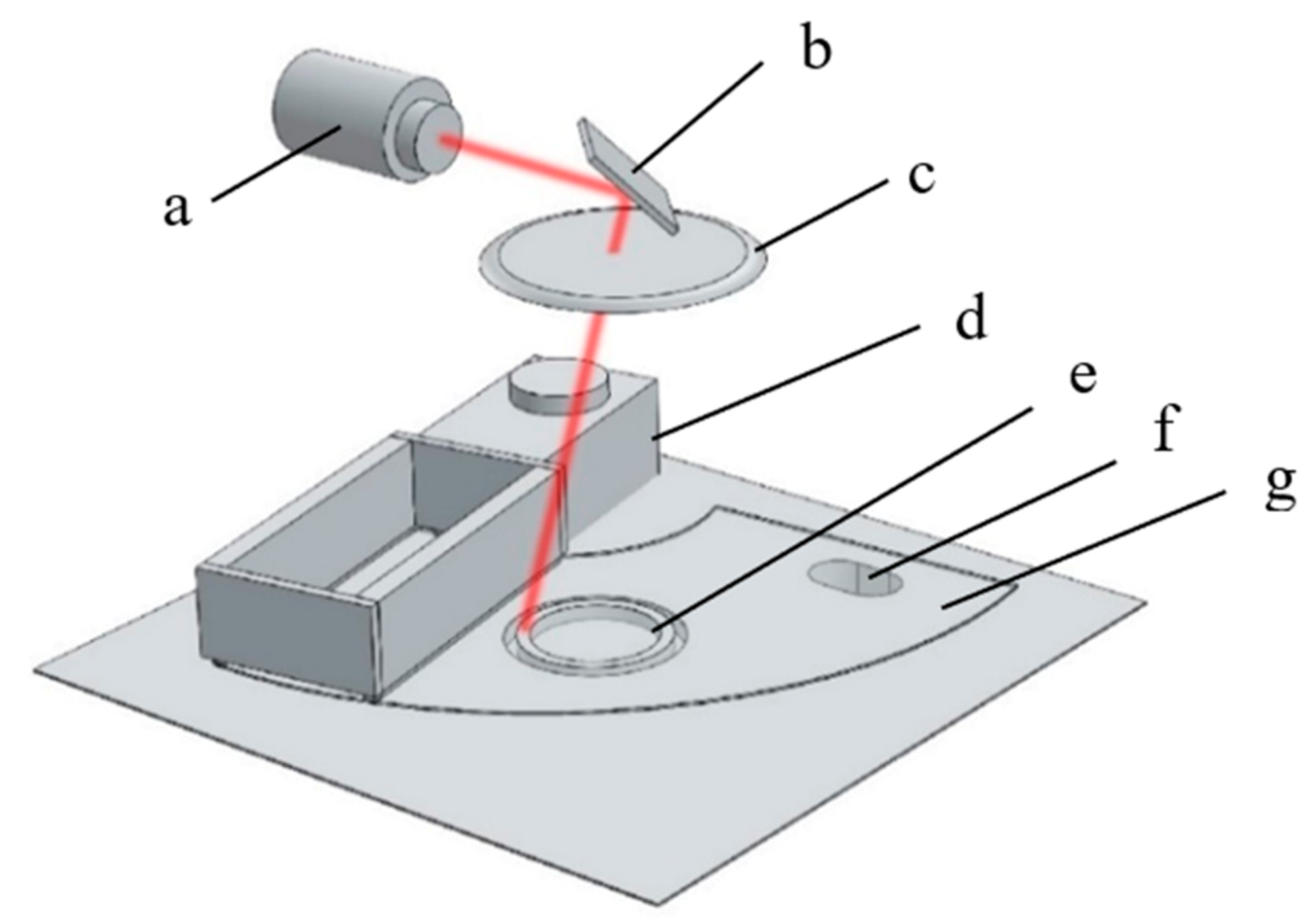
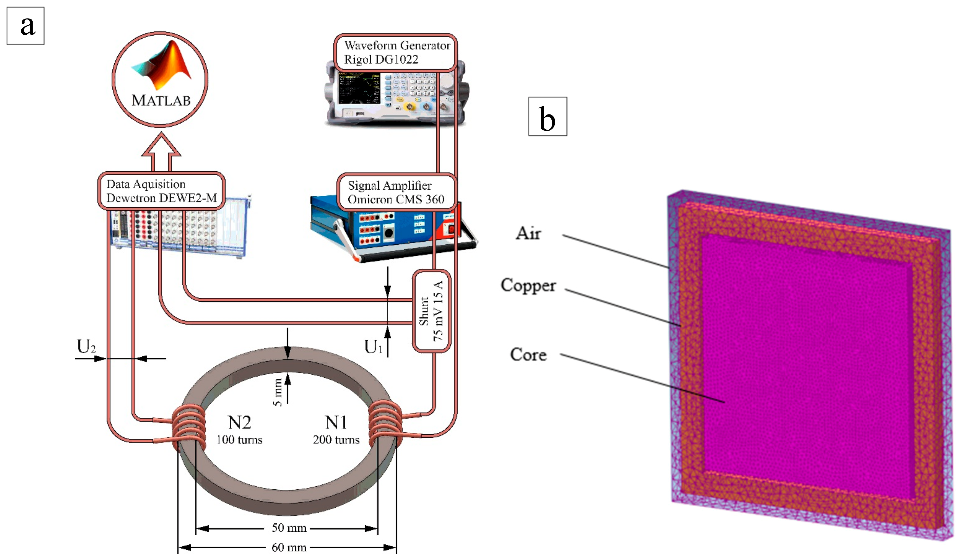
2.1. Printing System
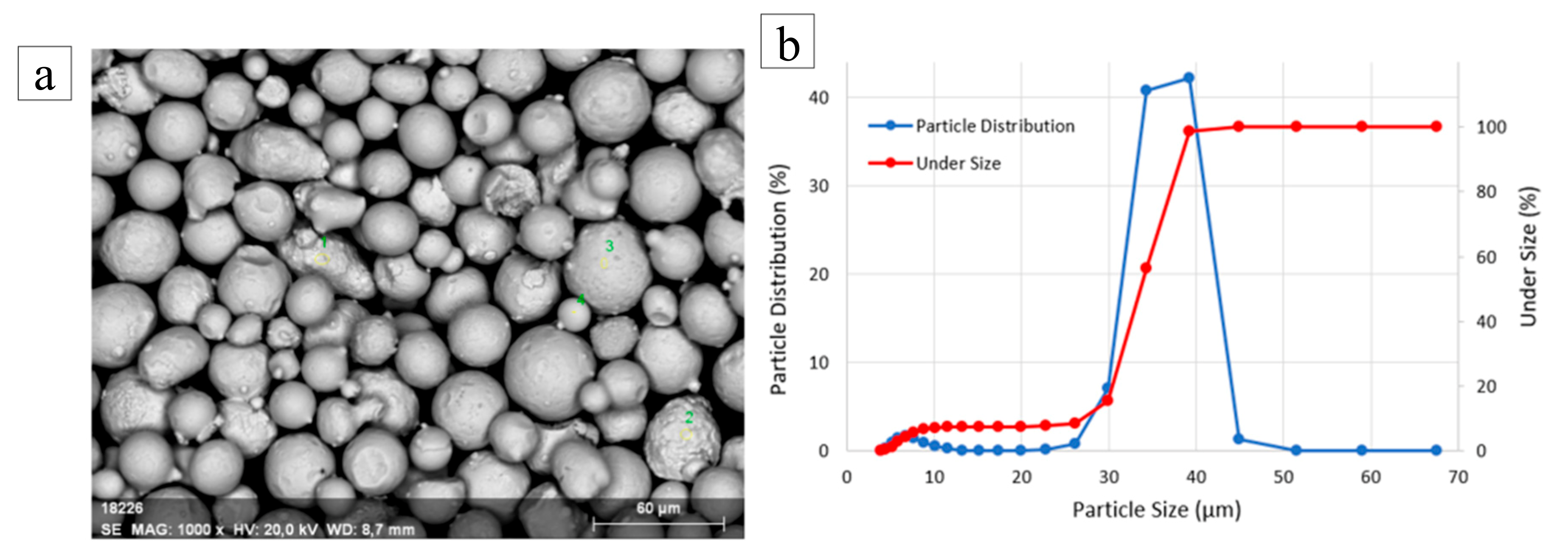
2.2. Powder Characterization
2.3. Printing Parameters
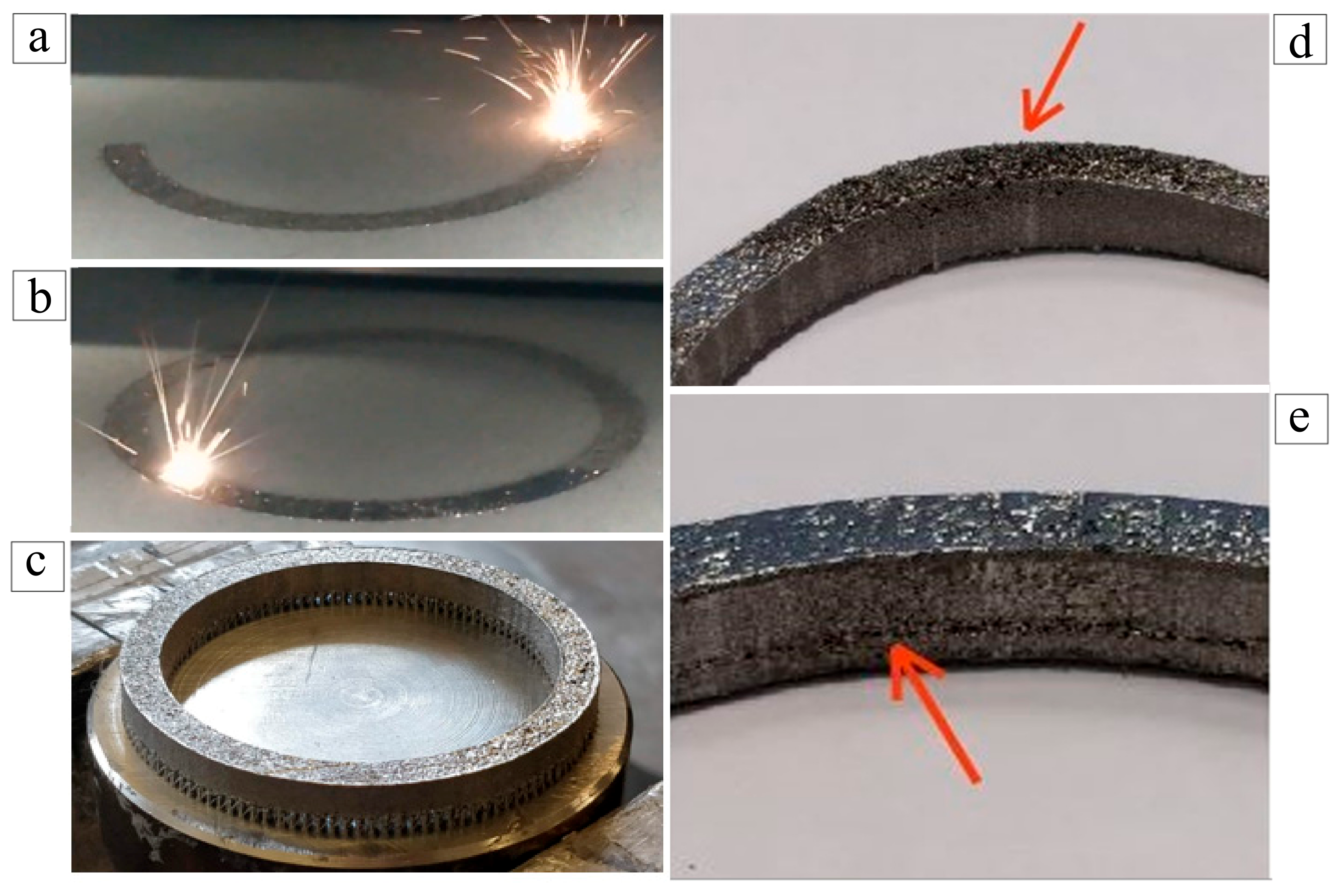
- Uneven growth (Figure 3d)—due powder balling, the uneven growth resulted in inferior density of the printed part, distorted part dimensions and printing termination, if growth is prominent enough to restrict the re-coater movements. Uneven powder deposition on the part was determined as the main cause for this issue, which was solved by double re-coater swiping to brush away the excess powder. Even growth of the printed part also seemed to be promoted by the laser re-melting strategy, as incremental melting of each layer seemed helpful for eliminating emerging irregularities; and
- Delaminations (Figure 3e)—were the result of excessive powder deposition on the printed part. It occurred when operating the printer without a feeder mechanism (suitable for parts with low height) and adding powder to the build chamber manually during an interrupt in the printing process. In that case, the build platform needed to be raised slightly manually after adding the extra powder, until only a thin coating of powder is visible on the printed part.
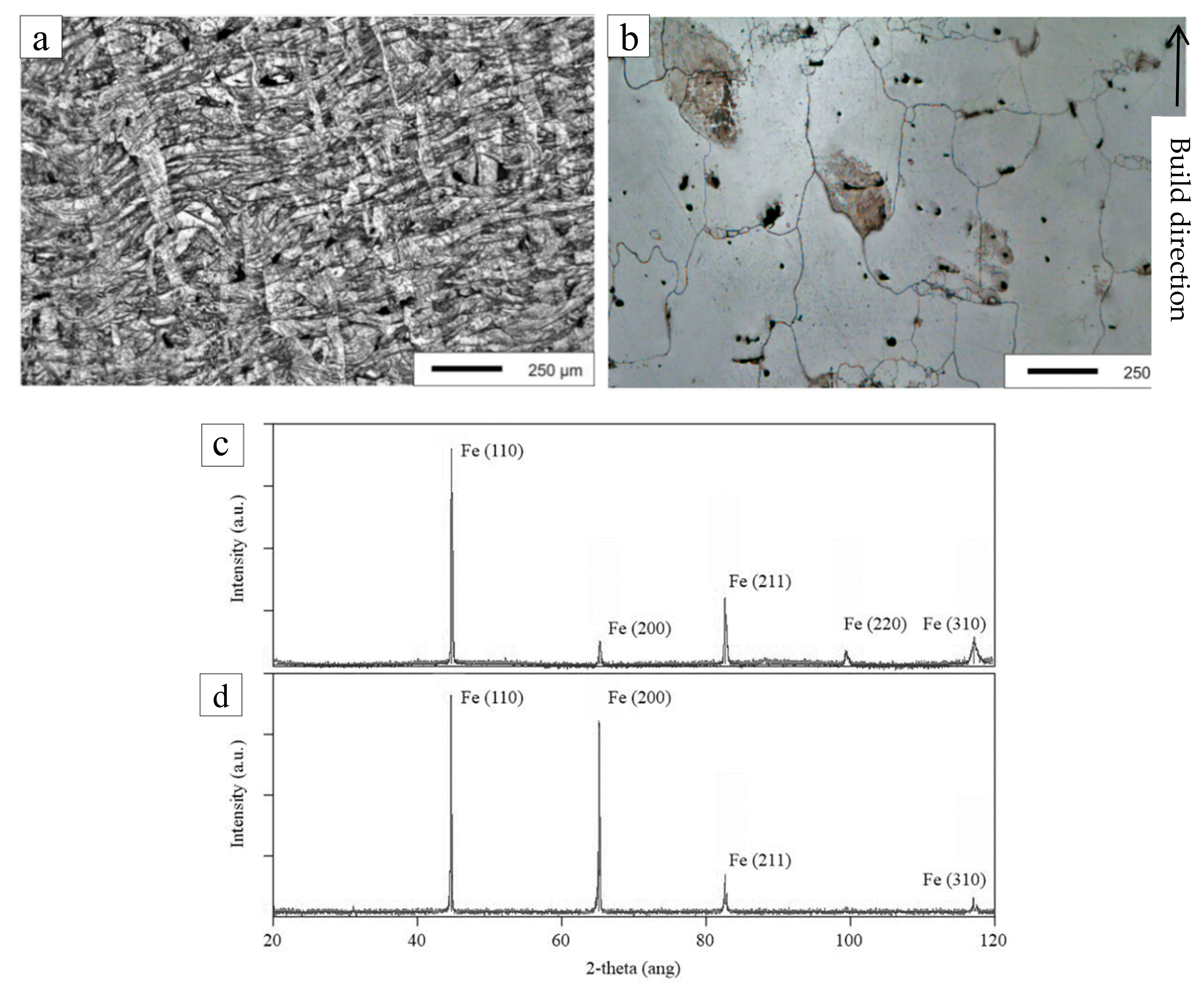
2.4. Sample Annealing and Crystal Structure
2.5. Methods of Magnetic Measurements and Losses Segregation
3. Results of Magnetic Measurements and Discussion
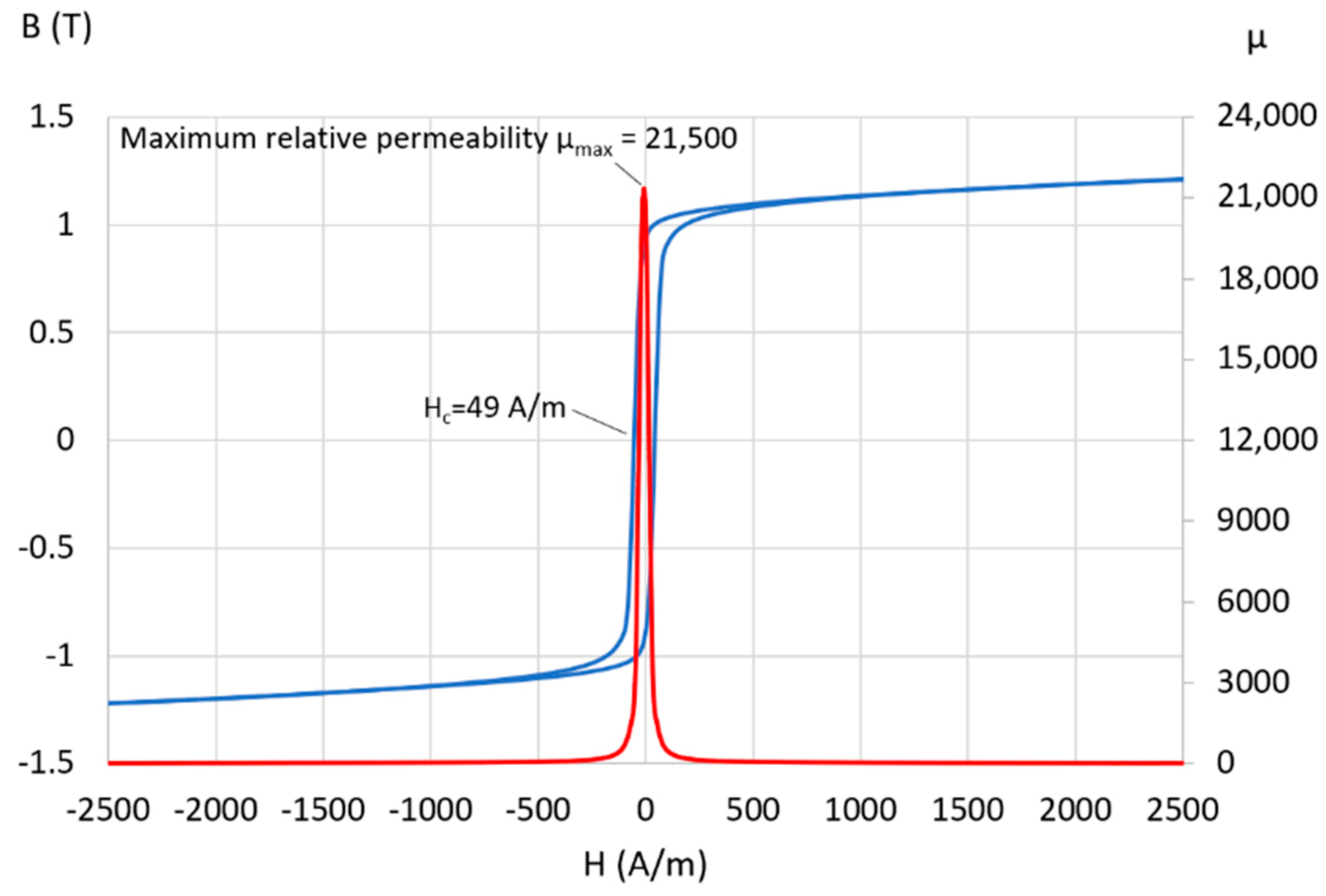
3.1. DC Properties
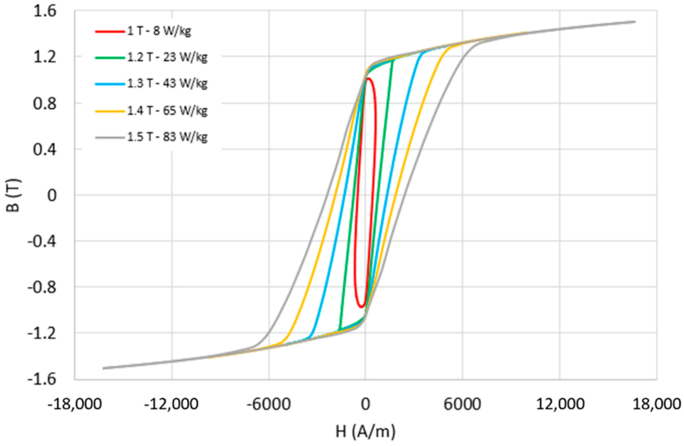
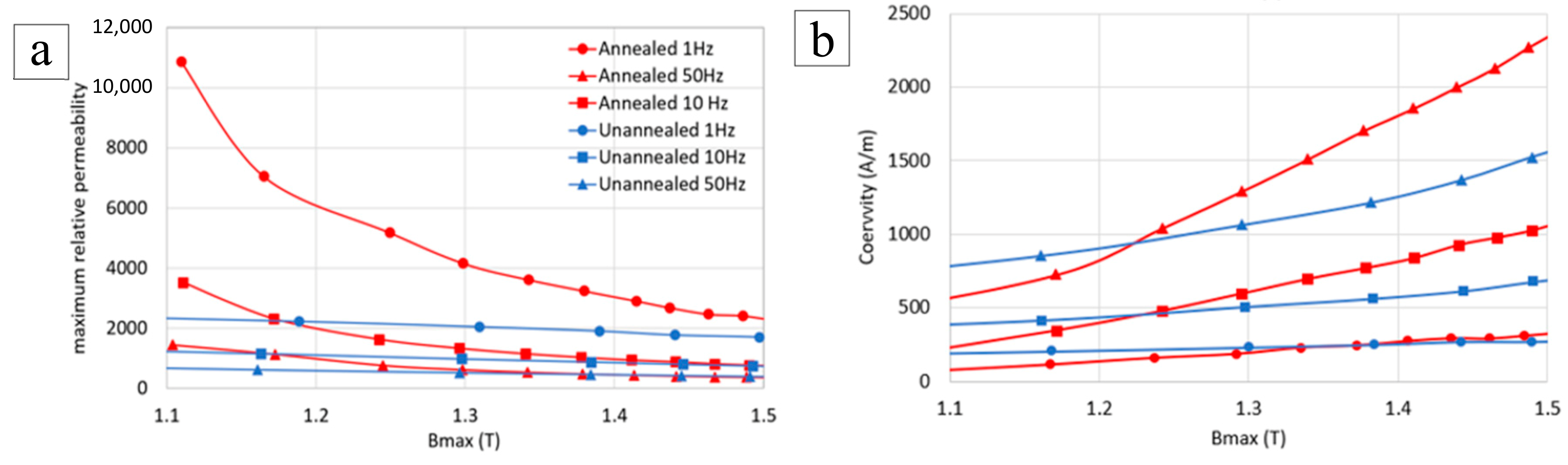
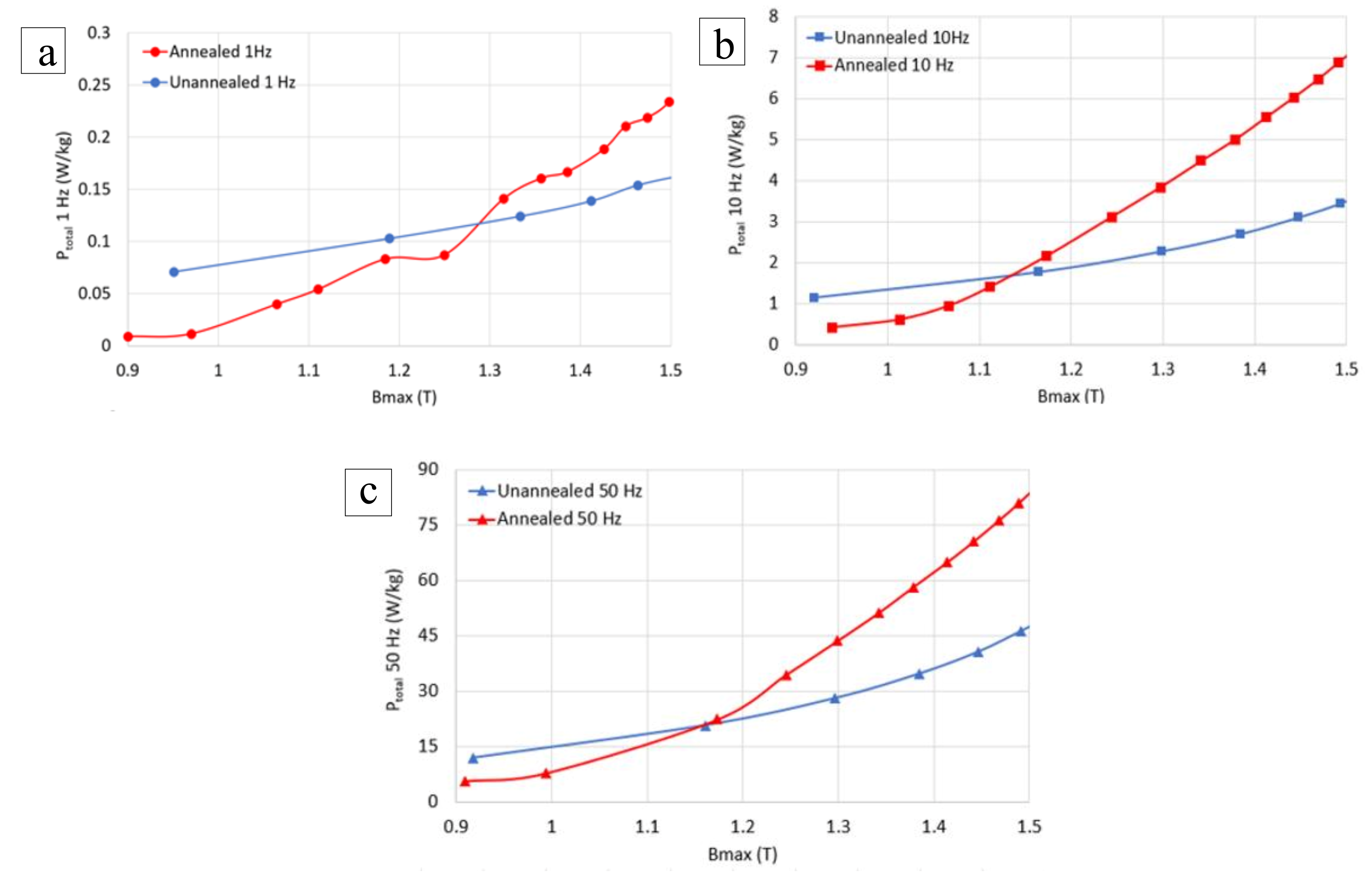
3.2. AC Properties
4. Future Work
5. Conclusions
Author Contributions
Funding
Acknowledgments
Conflicts of Interest
References
- Lammers, S.; Adam, G.; Schmid, H.-J.; Mrozek, R.; Oberacker, R.; Hoffmann, M.J.; Quattrone, F.; Ponick, B. Additive Manufacturing of a lightweight rotor for a permanent magnet synchronous machine. In Proceedings of the 2016 6th International Electric Drives Production Conference (EDPC), Nuremberg, Germany, 30 November–1 December 2016; Institute of Electrical and Electronics Engineers (IEEE): Nuremberg, Germany, 2016; Volume 13, pp. 41–45. [Google Scholar]
- Zhang, Z.-Y.; Jhong, K.J.; Cheng, C.-W.; Huang, P.-W.; Tsai, M.-C.; Lee, W.-H. Metal 3D printing of synchronous reluctance motor. In Proceedings of the 2016 IEEE International Conference on Industrial Technology (ICIT), Taipei, Taiwan, 14–17 March 2016; Institute of Electrical and Electronics Engineers (IEEE): Taipei, Taiwan, 2016; pp. 1125–1128. [Google Scholar]
- Rassõlkin, A.; Kallaste, A.; Vaimann, T.; Tiismus, H. Control Challenges of 3D Printed Switched Reluctance Motor. In Proceedings of the 2019 26th International Workshop on Electric Drives: Improvement in Efficiency of Electric Drives (IWED), Moscow, Russia, 30 January–2 February 2019; Volume 1, pp. 1–5. [Google Scholar] [CrossRef]
- Simpson, N.; Mellor, P. Additive manufacturing of shaped profile windings for minimal AC loss in gapped inductors. In Proceedings of the 2017 IEEE International Electric Machines and Drives Conference (IEMDC), Miami, FL, USA, 21–24 May 2017; pp. 1–7. [Google Scholar] [CrossRef] [Green Version]
- Lorenz, F.; Rudolph, J.; Wemer, R. Design of 3D Printed High Performance Windings for Switched Reluctance Machines. In Proceedings of the 2018 XIII International Conference on Electrical Machines (ICEM), Alexandroupoli, Greece, 3–6 September 2018; pp. 2451–2457. [Google Scholar] [CrossRef]
- Tate, J.G.; Richardson, B.; Love, L. Additive Manufacturing for Low Volume Bearings; Office of Scientific and Technical Information (OSTI): Oak Ridge, TN, USA, 2017.
- Aguilera, E.; Ramos, J.; Espalin, D.; Cedillos, F.; Muse, D.; Wicker, R.; MacDonald, E. 3D printing of electro mechanical systems. In Proceedings of the 24th Annual International Solid Freeform Fabrication Symposium: An Additive Manufacturing Conference, University of Texas at Austin, TX, USA, 12–14 August 2013; pp. 950–961. [Google Scholar]
- Tiismus, H.; Kallaste, A.; Vaimann, T.; Rassolkin, A.; Belahcen, A. Technologies for Additive Manufacturing of Electrical Machines. In Proceedings of the 2019 20th International Conference of Young Specialists on Micro/Nanotechnologies and Electron Devices (EDM), Erlagol (Altai Republic), Russia, 29 June–3 July 2019; pp. 651–655. [Google Scholar] [CrossRef] [Green Version]
- Silbernagel, C.; Gargalis, L.; Ashcroft, I.; Hague, R.; Galea, M.; Dickens, P. Electrical resistivity of pure copper processed by medium-powered laser powder bed fusion additive manufacturing for use in electromagnetic applications. Addit. Manuf. 2019, 29, 100831. [Google Scholar] [CrossRef]
- Silbernagel, C.; Ashcroft, I.; Dickens, P.; Galea, M. Electrical resistivity of additively manufactured AlSi10Mg for use in electric motors. Addit. Manuf. 2018, 21, 395–403. [Google Scholar] [CrossRef]
- Goll, D.; Schuller, D.; Martinek, G.; Kunert, T.; Schurr, J.; Sinz, C.; Schubert, T.; Bernthaler, T.; Riegel, H.; Schneider, G. Additive manufacturing of soft magnetic materials and components. Addit. Manuf. 2019, 27, 428–439. [Google Scholar] [CrossRef]
- Garibaldi, M.; Ashcroft, I.; Lemke, J.; Simonelli, M.; Hague, R. Effect of annealing on the microstructure and magnetic properties of soft magnetic Fe-Si produced via laser additive manufacturing. Scr. Mater. 2018, 142, 121–125. [Google Scholar] [CrossRef]
- Plotkowski, A.; Pries, J.; List, F.; Nandwana, P.; Stump, B.; Carver, K.; Dehoff, R. Influence of scan pattern and geometry on the microstructure and soft-magnetic performance of additively manufactured Fe-Si. Addit. Manuf. 2019, 29, 100781. [Google Scholar] [CrossRef]
- Riipinen, T.; Metsä-Kortelainen, S.; Lindroos, T.; Keränen, J.; Manninen, A.; Pippuri-Makelainen, J. Properties of soft magnetic Fe-Co-V alloy produced by laser powder bed fusion. Rapid Prototyp. J. 2019, 25, 699–707. [Google Scholar] [CrossRef]
- Kang, N.; El Mansori, M.; Guittonneau, F.; Liao, H.; Fu, Y.; Aubry, E. Controllable mesostructure, magnetic properties of soft magnetic Fe-Ni-Si by using selective laser melting from nickel coated high silicon steel powder. Appl. Surf. Sci. 2018, 455, 736–741. [Google Scholar] [CrossRef] [Green Version]
- Chen, W.; Liu, J.; Cheng, Z.; Lin, X.; Zhu, J. Effect of Chromium on Microstructure, Ordered Phase and Magnetic Properties of Fe-6.5 wt%Si Alloy. Mater. Today: Proc. 2015, 2, S314–S318. [Google Scholar] [CrossRef]
- Oxley, P.; Goodell, J., Jr.; Molt, R. Magnetic properties of stainless steels at room and cryogenic temperatures. J. Magn. Magn. Mater. 2009, 321, 2107–2114. [Google Scholar] [CrossRef]
- Yasa, E.; Deckers, J.; Kruth, J.-P. The investigation of the influence of laser re-melting on density, surface quality and microstructure of selective laser melting parts. Rapid Prototyp. J. 2011, 17, 312–327. [Google Scholar] [CrossRef]
- Yang, X.; Liu, J.; Cui, X.; Jin, G.; Liu, Z.; Chen, Y.; Feng, X. Effect of remelting on microstructure and magnetic properties of Fe-Co-based alloys produced by laser additive manufacturing. J. Phys. Chem. Solids 2019, 130, 210–216. [Google Scholar] [CrossRef]
- Liu, B.; Li, B.-Q.; Li, Z. Selective laser remelting of an additive layer manufacturing process on AlSi10Mg. Results Phys. 2019, 12, 982–988. [Google Scholar] [CrossRef]
- Ouyang, G.; Chen, X.; Liang, Y.; Macziewski, C.; Cui, J. Review of Fe-6.5 wt%Si high silicon steel—A promising soft magnetic material for sub-kHz application. J. Magn. Magn. Mater. 2019, 481, 234–250. [Google Scholar] [CrossRef]
- European Committee for Electrotechnical Standardization. European Standard EN 60404-6: Magnetic Materials—Part 6: Methods of Measurement of the Magnetic Properties of Magnetically Soft Metallic and Powder Materials at Frequencies in the Range 20 Hz to 100 kHz by the Use of Ring Specimens; International Electrotechnical Commission: Geneva, Switzerland, 2004; TC-68; Available online: http://www.evs.ee/et/iec-60404-6-2018 (accessed on 9 June 2020).
- European Committee for Electrotechnical Standardization. European Standard EN 60404-4: Magnetic Materials—Part 4: Methods of Measurement of d.c. Magnetic Properties of Iron and Steel; International Electrotechnical Commission: Geneva, Switzerland, 2002; TC-68; Available online: http://www.evs.ee/et/evs-en-60404-4-2002-a2-2009 (accessed on 9 June 2020).
- Garcia, J.; Rivas, M. A quasi-static magnetic hysteresis loop measurement system with drift correction. IEEE Trans. Magn. 2005, 42, 15–17. [Google Scholar] [CrossRef]
- Goldman, A. Handbook of Modern Ferromagnetic Materials; Springer Science and Business Media LLC: Pittsburgh, PA, USA, 1999. [Google Scholar]
- Globus, A.I. Magnetization Mechanisms Some Physical Considerations About the Domain Wall Size Theory of Magnetization Mechanisms. J. Phys. Colloq. 1977, 38, C1. [Google Scholar] [CrossRef]
- Brissonneau, P. Non-oriented Si-Fe Sheets. J. Magn. Magn. Mater. 1980, 19, 52–59. [Google Scholar] [CrossRef]
- Tumanski, S. Handbook of Magnetic Measurements; CRC Press: Boca Raton, FL, USA, 2016. [Google Scholar]
- Hoganas. Material Data: Somaloy. Available online: http://www.hoganas.com/electromagnetic (accessed on 9 June 2020).
- Shimanaka, H.; Ito, Y.; Matsumara, K.; Fukuda, B. Recent development of non-oriented electrical steel sheets. J. Magn. Magn. Mater. 1982, 26, 57–64. [Google Scholar] [CrossRef]
- Almeida, A.A.; Rodrigues, D.L., Jr.; Perassa, L.S.P.; Leicht, J.; Landgraf, F.J.G. Anomalous loss hysteresis loop. Mater. Res. 2014, 17, 494–497. [Google Scholar] [CrossRef] [Green Version]
- Krings, A.; Soulard, J. Overview and Comparison of Iron Loss Models for Electrical Machines. J. Electr. Eng. 2010, 10, 162–169. [Google Scholar]
- Eggers, D.; Steentjes, S.; Hameyer, K. Advanced Iron-Loss Estimation for Nonlinear Material Behavior. IEEE Trans. Magn. 2012, 48, 3021–3024. [Google Scholar] [CrossRef]
- Steentjes, S.; Leßmann, M.; Hameyer, K. Semi-physical parameter identification for an iron-loss formula allowing loss-separation. J. Appl. Phys. 2013, 113, 17A319. [Google Scholar] [CrossRef]
- Elfgen, S.; Franck, D.; Hameyer, K. Characterisation of soft magnetic materials by measurement: Evaluation of uncertainties up to 1.8 T and 9 kHz. AIP Adv. 2018, 8, 47208. [Google Scholar] [CrossRef]
- Karthaus, J.; Steentjes, S.; Leuning, N.; Hameyer, K. Effect of mechanical stress on different iron loss components up to high frequencies and magnetic flux densities. COMPEL Int. J. Comput. Math. Electr. Electron. Eng. 2017, 36, 580–592. [Google Scholar] [CrossRef]
- Oda, Y.; Okubo, T.; Takata, M. Recent Development of Non-Oriented Electrical Steel in JFE Steel; Techical Report for JFE. Rep., 21; JFE Steel Corporation: Kawasaki, Japan, 2016; pp. 7–13. [Google Scholar]
- Aerosint. Selective Powder Deposition for AM. Available online: https://aerosint.com/ (accessed on 11 June 2020).
- Gangireddy, S.; Komarasamy, M.; Faierson, E.J.; Mishra, R.S. High strain rate mechanical behavior of Ti-6Al-4V octet lattice structures additively manufactured by selective laser melting (SLM). Mater. Sci. Eng. A 2019, 745, 231–239. [Google Scholar] [CrossRef]
- Leary, M.; Mazur, M.; Williams, H.; Yang, E.; Alghamdi, A.; Lozanovski, B.; Zhang, X.; Shidid, D.; Farahbod-Sternahl, L.; Witt, G.; et al. Inconel 625 lattice structures manufactured by selective laser melting (SLM): Mechanical properties, deformation and failure modes. Mater. Des. 2018, 157, 179–199. [Google Scholar] [CrossRef]
- Maconachie, T.; Leary, M.; Lozanovski, B.; Zhang, X.; Qian, M.; Faruque, O.; Brandt, M.; Zhang, X. SLM lattice structures: Properties, performance, applications and challenges. Mater. Des. 2019, 183, 108137. [Google Scholar] [CrossRef]


| Elements | Fe | Si | Cr |
|---|---|---|---|
| Wt % | Balance | 4 | 1.3 |
| Parameter | Inital | Final |
|---|---|---|
| Layer thickness | 35 μm | 35 μm |
| Hatch distance | 60 μm | 60 μm |
| Laser Power | 75 W | 50 W/75 W |
| Scanning velocity | 1 m/s | 1 m/s/0.75 m/s |
| Laser spot size | ~100 μm | ~100 μm |
| Pre-Heating | 0 °C | 200 °C |
| Environment | Argon | Argon |
| Oxygen content | ~0.35% | ~0.35% |
| Sample | 1 Hz (W/kg) | 10 Hz (W/kg) | 50 Hz (W/kg) |
|---|---|---|---|
| Annealed, 1 T | 0.022 | 0.60 | 8.17 |
| Unannealed, 1 T | 0.077 | 1.37 | 14.17 |
| Annealed, 1.5 T | 0.23 | 7.1 | 83.7 |
| Unannealed, 1.5 T | 0.16 | 3.5 | 47.3 |
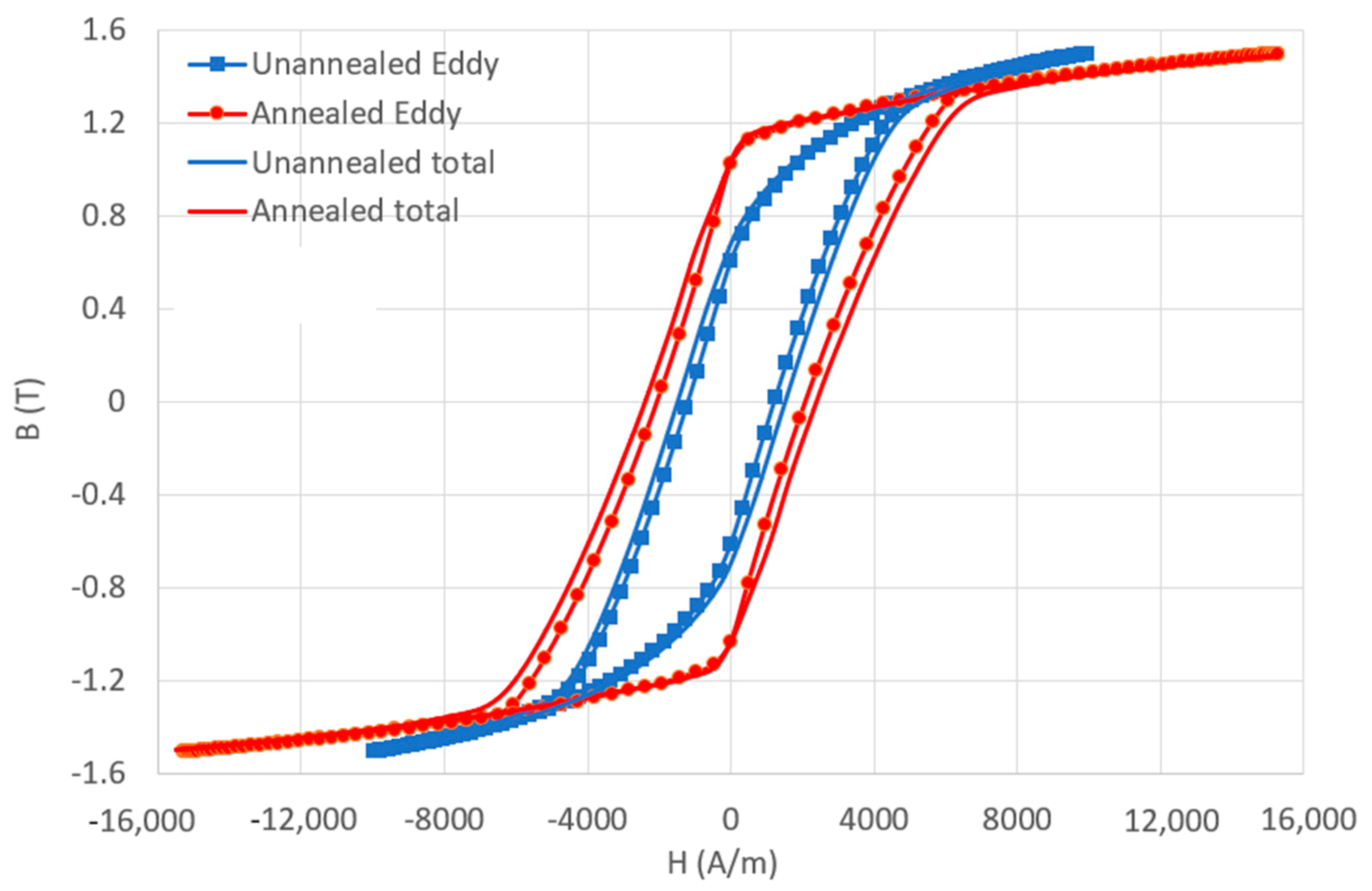
| Sample | Total (W/kg) | Hysteresis (W/kg) | Eddy (W/kg) | Excess (W/kg) |
|---|---|---|---|---|
| Annealed, 1 T | 8.17 | 0.95 | 6.26 | 0.96 |
| Unannealed, 1 T | 14.17 | 3.65 | 7.85 | 2.67 |
| Annealed, 1.5 T | 83.7 | 2.81 | 74.3 | 6.59 |
| Unannealed, 1.5 T | 47.3 | 7.18 | 37.6 | 2.52 |
© 2020 by the authors. Licensee MDPI, Basel, Switzerland. This article is an open access article distributed under the terms and conditions of the Creative Commons Attribution (CC BY) license (http://creativecommons.org/licenses/by/4.0/).
Share and Cite
Tiismus, H.; Kallaste, A.; Belahcen, A.; Vaimann, T.; Rassõlkin, A.; Lukichev, D. Hysteresis Measurements and Numerical Losses Segregation of Additively Manufactured Silicon Steel for 3D Printing Electrical Machines. Appl. Sci. 2020, 10, 6515. https://0-doi-org.brum.beds.ac.uk/10.3390/app10186515
Tiismus H, Kallaste A, Belahcen A, Vaimann T, Rassõlkin A, Lukichev D. Hysteresis Measurements and Numerical Losses Segregation of Additively Manufactured Silicon Steel for 3D Printing Electrical Machines. Applied Sciences. 2020; 10(18):6515. https://0-doi-org.brum.beds.ac.uk/10.3390/app10186515
Chicago/Turabian StyleTiismus, Hans, Ants Kallaste, Anouar Belahcen, Toomas Vaimann, Anton Rassõlkin, and Dmitry Lukichev. 2020. "Hysteresis Measurements and Numerical Losses Segregation of Additively Manufactured Silicon Steel for 3D Printing Electrical Machines" Applied Sciences 10, no. 18: 6515. https://0-doi-org.brum.beds.ac.uk/10.3390/app10186515