Article

Nanoparticle Deposition of Fluoropolymer CYTOP via Holographic Femtosecond Laser Processing and Its Biochip Application

1
Graduate School of Science and Technology, Hirosaki University, 3 Bunkyo-Cho, Hirosaki, Aomori 036-8561, Japan
2
Graduate School of Agriculture and Life Science, Hirosaki University, 3 Bunkyo-Cho, Hirosaki, Aomori 036-8561, Japan
*
Author to whom correspondence should be addressed.
Submission received: 19 September 2020 / Revised: 8 October 2020 / Accepted: 13 October 2020 / Published: 16 October 2020
(This article belongs to the Special Issue Biomimetic Laser Processing Part II)

Abstract

:

Featured Application

The presented holographic femtosecond laser processing technique may achieve a better performance of CYTOP nanoparticle generation compared to the conventional single laser beam processing, and the application of CYTOP nanoparticle deposition lies in the area of biochip and coating industries, where a superhydrophobic surface is required.

Abstract

The fundamental characteristics of nanoparticle (NP) deposition of the fluoropolymer CYTOP using a femtosecond (fs) laser were investigated. In previous studies, we have demonstrated the microfluidic fabrication of CYTOP, which enables clear microscopic observation of the fluid boundary because of its low refractive index, as well as that of water. In the present work, we generated CYTOP NPs using holographic fs laser processing with a spatial light modulator to demonstrate the capabilities of this functional polymer. We established a deposition technique via five-dot parallel fs laser beam irradiation for fibrous network and monolayer structures composed of CYTOP NPs on the surface of glass slides by manipulating the various fundamental laser processing parameters. The network structure on the glass surface exhibits superhydrophobic behavior, while the monolayer structure performs almost the same wettability as that of CYTOP thin film. After an investigation of the surface features of the NPs deposited onto the glass, the combination of the holographic fs laser deposition and the removal of CYTOP NPs was used to selectively pattern CYTOP NPs on the glass slide for HeLa cell culturing. Consequently, cells were selectively cultured on the glass surface where the laser removal of deposited NPs was carried out.

1. Introduction

Within the past 20 years, microelectromechanical system (MEMS) and nanoelectromechanical system (NEMS) technologies have been used to fabricate small biochips for studying various phenomena in the biological sciences [1,2,3,4]. The commonly used conventional biochip materials are transparent glasses and polymers, which enable clear observation of reactions in embedded fluidics under a microscope. However, in the case of the fluid boundary, biochips fabricated using conventional materials do not provide sufficiently clear images because of refractive index mismatch between the biochip material and the medium in the fluidic system.
Asahi Glass Co. has developed a commercially available fluoropolymer, CYTOP, with unique properties, including a high degree of transparency toward radiation with wavelengths in the ultraviolet to infrared regions and a low refractive index almost equal to that of water. In addition, CYTOP exhibits other properties common to fluoropolymers, such as good heat and chemical resistances and good electrical insulating behavior [5]. Therefore, CYTOP is considered an attractive prospective biochip material. In previous research, we established laser microfabrication techniques for CYTOP and clearly observed aquatic microorganisms near the fluid boundaries in fabricated CYTOP biochips [6,7,8]. To extend the applications of this polymer, we here attempt to generate CYTOP nanoparticles (NPs) using femtosecond (fs) laser processing and to use the deposited NPs in a biochip application.
NPs are particulate substances that have one dimension less than 100 nm at least. They have received much attention in a variety of research fields due to their unique properties and potential applications. To date, many methods have been developed for NP synthesis, which are usually based on sol-gel colloidal chemistry, plasma precursor decomposition, electrochemical etching, etc. Among these is the synthesis of NPs by laser ablation, which involves the generation of NPs by laser ablating a solid target. The method is attractive due to the simplicity in equipment configuration and low operation cost compared to the other methods. In particularly, many investigations have been devoted to NP formation through fs laser ablation since the rapid heating and cooling of ablated species caused by the ultrashort pulse duration has the potential to open a new avenue in NP synthesis. For example, Tull et al. [9] have demonstrated the formation of web-like structures composed of Si NP aggregates by the fs laser ablation. Venkatakrishnan et al. [10] fabricated the silica NPs on nanofibre during the silica glass ablation. Nano diamonds with an average particle size of 3.0 nm were generated by the fs laser ablation of diamond in deionized water [11].
However, one of the major shortcomings of conventional laser processing, including NP synthesis with fs lasers, is low fabrication efficiency. To overcome this problem, holographic laser processing using a spatial light modulator (SLM) has been actively researched to substantially improve the fabrication efficiency by shaping the laser beam into a desired pattern [12,13,14,15,16,17,18,19,20,21,22]. In particular, several papers on holographic fs laser processing have been reported, including papers on surface microfabrication using beam patterns with a desired shape [15,16,17] and massively parallel beam fabrication [18,19,20]. Therefore, in the present study, we used holographic fs laser processing to efficiently deposit CYTOP NPs onto glass slides and investigated the fundamental characteristics of the deposited NPs. Following the investigation, we used the holographic laser processing to partially pattern the CYTOP NPs on the glass surface and then used the patterned NPs to selectively culture HeLa cells.

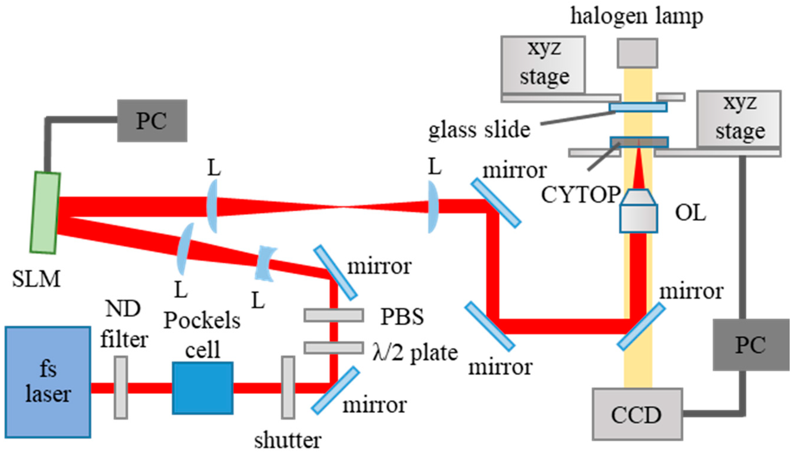
2. Materials and Methods

Figure 1 shows a schematic of the holographic fs laser processing setup used to deposit CYTOP NPs onto a glass slide. A fs laser (Ti:sapphire laser: 775 nm, 180 fs) was used as the light source. The repetition rate, which was controlled using a Pockels cell, was varied from 1 Hz to 1 kHz; the laser power was adjusted by neutral density filters, a half-wavelength plate, and a polarizer. The beam was diffracted by a computer-generated hologram displayed on the SLM and was transformed to a desired pattern on the CYTOP substrate (thickness: 200 µm) through a 20× objective lens with a numerical aperture of 0.46 (focal length = 10.0 mm). Details of the experimental setup used for holographic fs laser processing are available elsewhere [15]. The laser output before the objective lens and the number of pulses were varied from 3.0 to 8.0 µJ/pulse and from 1 to 10,000 pulses, respectively. The CYTOP substrate and the glass slide (thickness: 1.3 mm) were positioned in parallel, and the movement of each substrate was controlled via a computer-controlled xyz stage. The distance between the CYTOP and the glass slide was also fixed from 100 to 10,000 µm during the experiment.
To deposit CYTOP NPs onto the glass slide, five-dot parallel beams with an 8 µm pitch were generated by the holographic fs laser processing technique [21] and the surface of the CYTOP substrate was ablated. The morphology of the deposited NPs was observed and analyzed by scanning electron microscopy (SEM) and atomic force microscopy (AFM). After the deposition, the wettability of the glass surface was evaluated by measuring the contact angle of 1 µL of pure water dropped onto the glass surface using a pipette.
After the investigation of the CYTOP NPs, glass slide fabrication via holographic fs laser processing of CYTOP for selective cell culturing was carried out. First, CYTOP NPs were deposited onto a glass slide via five-dot parallel-beam irradiation, as previously described. A line-shaped beam was then also generated by holographic laser processing [16,22] to partially remove the deposited NPs and clearly divide the bare glass surface and the NP-deposited areas.
After fabrication of the glass slides, HeLa cells were cultured on the glass for 1 day at 37 °C in Dulbecco’s modified Eagle’s medium (DMEM) containing 100 units/mL penicillin, 100 µg/mL of streptomycin, and 10% (v/v) fetal bovine serum (FBS) in humidified air containing 5% CO2. After the cell culture, an optical microscope was used in phase-contrast mode to observe the selectively cultured cells on the glass slide.

3. Results

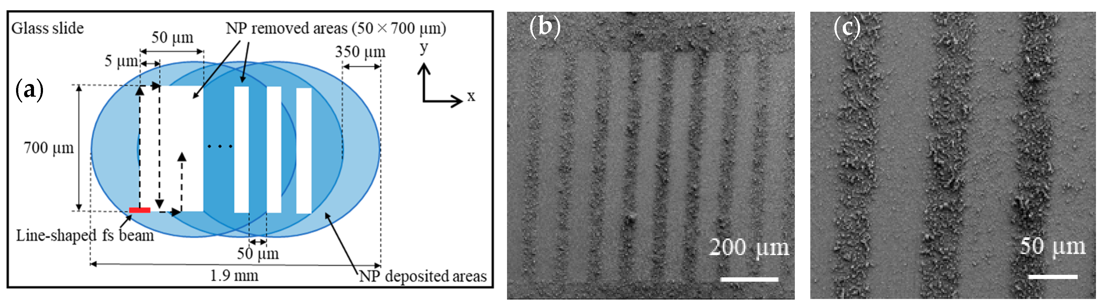
3.1. Fundamental Characteristics of CYTOP NP Deposition

To investigate the fundamental characteristics of the process of CYTOP NP deposition onto glass slides via five-dot parallel fs laser-beam irradiation, the effects of varying experimental conditions such as the CYTOP-glass slide distance and the laser processing parameters were determined. After the deposition, the morphology of the glass surface was characterized by SEM and AFM.

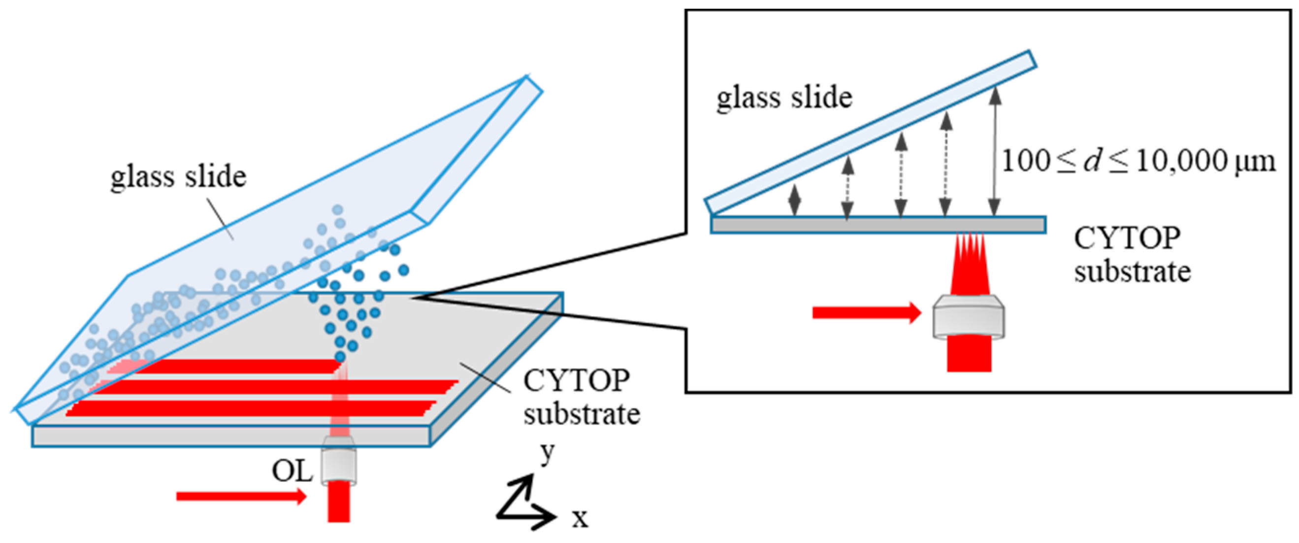
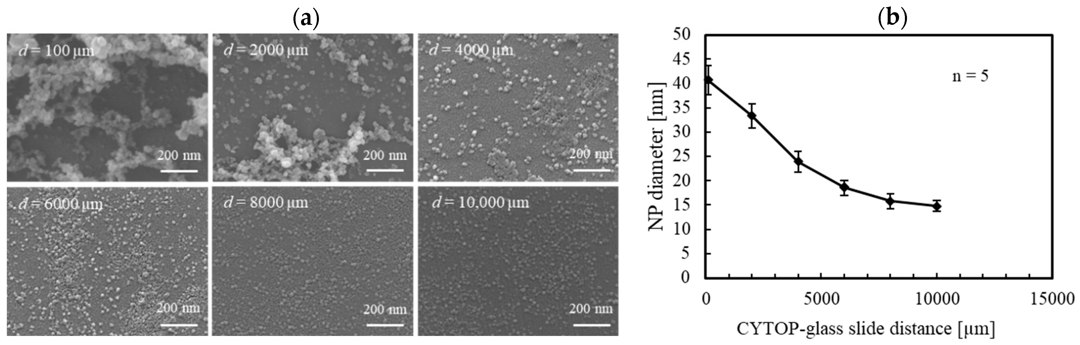
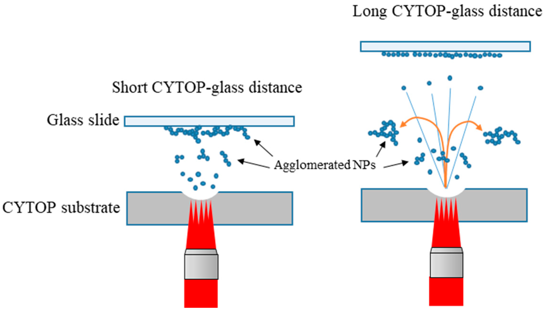
3.1.1. Influence of the CYTOP–Glass Slide Distance on the NP Deposition

To elucidate the influence of the CYTOP-glass slide distance on the properties of deposited CYTOP NPs, a glass slide was obliquely placed on the CYTOP substrate, as shown in Figure 2. In this experiment, a fs laser beam with a pulse energy of 5.0 J/pulse before the objective lens was scanned at the CYTOP surface with the speed of 1500 µm/s. After the laser scanning, the NP-deposited areas on the glass surface 100 to 10,000 µm from the CYTOP substrate were observed by SEM to characterize the NP deposition tendency at different CYTOP-glass slide distances.
Figure 3 shows SEM images of CYTOP NPs deposited onto the glass slide at different CYTOP-glass distances and the relationship between the diameter of the NPs and the CYTOP-glass slide distance. The average diameter of the NPs was calculated by counting NPs in 200 × 200 nm2 areas of the glass slide at each distance. The calculation was repeated five times. When the CYTOP-glass slide distance was less than 6000 µm, NPs approximately 10–100 nm in diameter agglomerated with other NPs. When the distance exceeded 6000 µm, particles 10–30 nm in diameter were uniformly distributed on the glass slide. Figure 3b shows that the particle size gradually decreases with increasing CYTOP-glass distance. It seems that two different types of surface morphology composed of NP aggregates or relatively small individual NPs can be created on the glass slide depending on the CYTOP-glass slide distance.

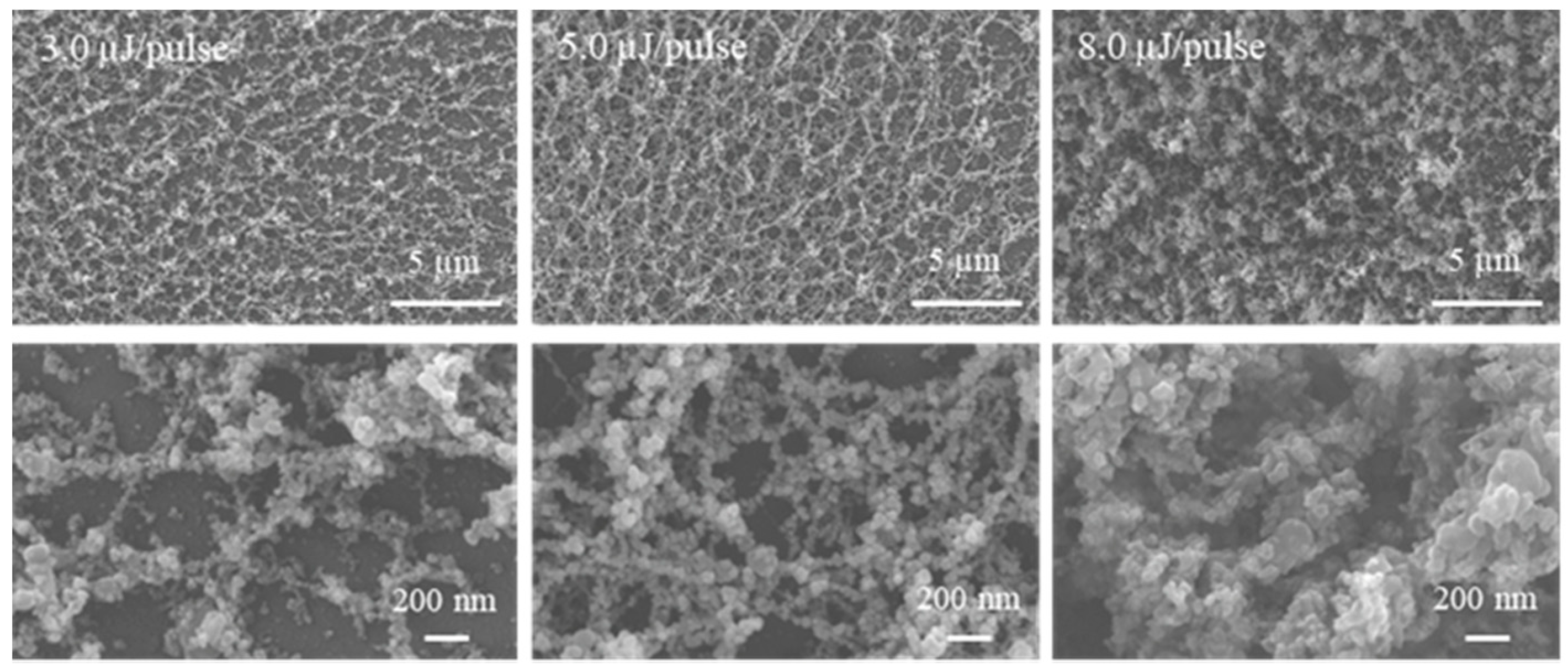
3.1.2. Influence of Laser Processing Parameters on the NP Deposition

The morphology of the deposited NPs on the glass also changed depending on laser processing parameters, such as the number of pulses and the pulse energy. Figure 4a shows SEM images of the deposited NPs on the glass when the number of pulses was varied from 1 to 10,000. The lower SEM images show enlarged views of the upper images. In this experiment, the pulse energy and the CYTOP-glass distance were kept constant at 5 µJ/pulse and 100 µm, respectively (note that, in this experiment, a glass slide was placed horizontally above the CYTOP substrate, as shown in Figure 1).
As shown in Figure 4a, fibrous network structures composed of NP aggregates were formed on the glass surface, and the pores in the network structures became narrower with an increasing number of pulses. We also conducted the NP deposition at a greater CYTOP-glass slide distance for comparison. Figure 4b shows overall (left) and enlarged (upper right) SEM images, a histogram of the NP sizes (middle) obtained from the enlarged SEM, and an AFM image (right) of the glass surface after 10,000 pulse irradiations at a CYTOP-glass distance of 4000 µm. It can be seen from the images that NPs were distributed fairly uniformly on the glass slide. The average diameter of the NPs was 26.3 nm, with a standard deviation of ± 8.6 nm. The NPs were highly monodispersive and close-packed to form a monolayer structure. The surface roughness of the monolayer structure was 18.9 ± 1.37 nm.
Table 1 shows a summary of the glass morphologies after the fs laser irradiation with different CYTOP–glass distances and different numbers of pulses. The pulse energy was maintained at 5 µJ/pulse. As shown in Table 1, when the CYTOP-glass distance was less than 1000 µm, network structures tended to deposit on the glass slide. With increasing distance, the monolayer structure was more likely to be formed. Thus, the CYTOP-glass slide distance strongly influenced the morphology of the NP-deposited glass.
In addition, we investigated the glass surface after NP deposition at various pulse energies from 3.0 to 8.0 µJ/pulse, as shown in the SEM images in Figure 5. Enlarged views of the deposited NPs are shown at the bottom. The number of pulses and the CYTOP-glass distance was kept constant at 1000 pulses and 100 µm, respectively.
The images in Figure 5 show that, when the pulse energy was less than 5 µJ/pulse, the network structures of NP aggregates gradually formed closed-rings and bridges and became dense with increasing pulse energy. By contrast, when the pulse energy was 8 µJ/pulse, agglomerates composed of melted NP aggregates were deposited onto the glass slide.

3.2. Wettability of the Deposited CYTOP NPs

The wettability of the network and monolayer structures composed of CYTOP NPs deposited onto glass slides was evaluated. Again, five-dot parallel beams were irradiated onto the same areas of the CYTOP surface to deposit NPs onto the glass slides. The pulse energy and the number of pulses were 5 µJ/pulse and 10,000, respectively. The CYTOP-glass distance was selected as 100 or 4000 µm for deposition of the network or monolayer structure on each glass substrate, respectively. Figure 6 shows an overall SEM image of NPs deposited onto the glass slide following fs laser irradiation at a CYTOP-glass distance of 100 µm and a schematic of the NP-distributed areas.
Figure 6a shows that the CYTOP NPs were deposited radially with a diameter of 1200 µm onto the glass slide. Changes in the surface morphology of the deposited NPs are discernible depending on the distance from the center of the NP-distributed areas, as shown in Figure 6b. Figure 6i–iii shows that melted NP aggregates are agglomerated within a distance of 170 µm from the center of the NP-deposited areas. Dense network structures are deposited at 170–520 µm, and short, chain-like NP aggregates are observed at distances between 520 and 600 µm; that is, debris of network structures is formed. Thus almost 70% of the NP-deposited areas are composed of network structures. In the case of a CYTOP–glass distance of 4000 µm, the monolayer structure (see Figure 4b) is deposited radially, with a diameter of 3000 µm.
After NP deposition, we evaluated the wettability of the CYTOP structures by measuring the water contact angle of each structure. Figure 7 shows microscopic images of 1 µL water droplets on (a) a normal glass slide, (b) a CYTOP thin film [23], (c) monolayer, and (d) network structures composed of CYTOP NPs deposited onto glass slides. Table 2 summarizes the surface roughness, contact angle, and wettability of each substrate.
The results in Figure 7 and Table 2 show that a low contact angle was observed for the glass surface, which was expected because the glass slide surface generally exhibits hydrophilic behavior. However, almost the same contact angle was observed on the CYTOP thin film and on the monolayer structure composed of CYTOP NPs on glass, as shown in Figure 7b and c. The highest contact angle of 158° was observed for the network structures deposited onto glass. These results indicate that the wettability of the glass surface can be varied from hydrophilic to superhydrophobic by altering the laser-processing parameters used for CYTOP NP deposition.

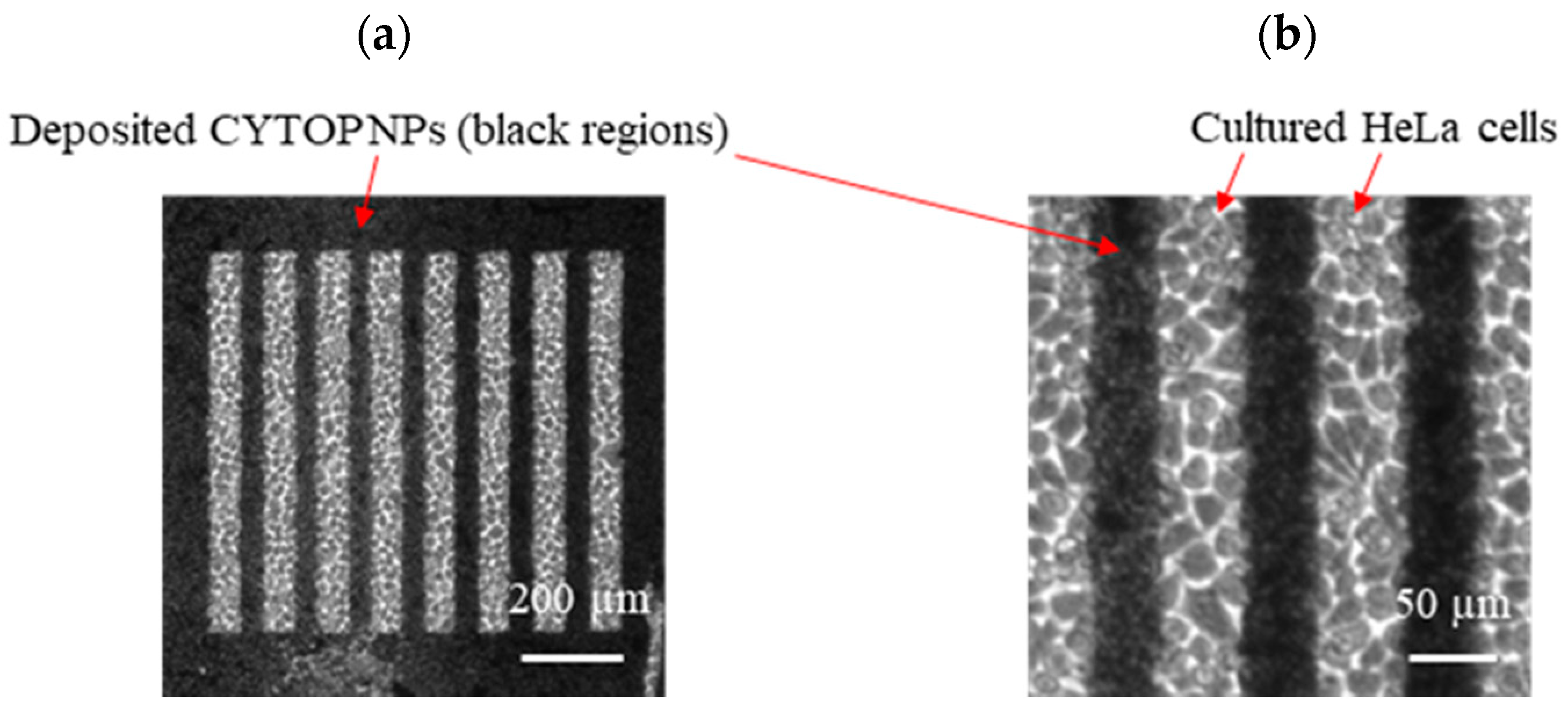
3.3. Selective Cell Culturing on the NP-Deposited Glass

The results show that deposition of CYTOP NP onto a glass slide can be used to render the glass surface superhydrophobic. We therefore attempted selective cell culturing on a glass slide with CYTOP NPs deposited. Figure 8a shows a schematic of the glass slide fabricated for the selective cell culturing. First, the previously used fs laser irradiation method with five-dot parallel beams was again used to deposit NP network structures onto glass slide. The pulse energy, number of pulses, and the CYTOP-glass distances were 5.0 µJ/pulse, 100 µm, and 10,000 pulses, respectively. After the 10,000 pulse irradiations, the glass slide was shifted 350 µm along the x-direction and the laser irradiation was repeated. As a result, ca. 70% of the NP-deposited areas were overlapped since the diameter of the deposited areas was measured to be ca. 1200 µm, as indicated in Figure 6b. This procedure was repeated three times to deposit the network structure over areas of approximately 1.9 × 1.2 mm2 on the glass slide. After deposition, a line-shaped fs laser beam was also generated via holographic laser processing to partially remove the deposited NPs to divide the glass and NP-deposited areas. The size of the line-shaped fs laser beam was 10 × 1.5 µm2 at the focal point. The pulse energy and the scanning speed of the laser beam used to remove the deposited network structures were 3.0 µJ/pulse and 100 µm/s, respectively. As shown in Figure 8a, the laser beam was scanned 700 µm line-by-line along the y-direction with a pitch of 5 µm. This scanning was repeated 10 times to remove 50 × 700 μm2 areas of deposited network structures. The laser beam was then shifted 50 µm for the next NP removal. Figure 8b and c show overall and enlarged SEM images of the fabricated glass slide after the fs laser parallel beam deposition and line-shaped removal of CYTOP NPs.
Figure 8b shows that deposited network structures on the glass slide were clearly removed by the line-shaped fs laser processing and that clear separation was achieved between the glass surface and the network structures of CYTOP NPs at the boundaries (Figure 8c). Following the glass fabrication process, we attempted to selectively culture HeLa cells on the fabricated glass slide; the results are shown in Figure 9.
Figure 9a shows that HeLa cells were selectively cultured on the glass surface where the line-shaped fs laser removal was carried out. In addition, no cells were cultured on the NP-deposited areas, as shown in the enlarged image of the boundaries between the glass and the deposited CYTOP NPs (Figure 9b). Thus, fs laser deposition of network structures composed of CYTOP NPs imparted functionality to the glass surface and is potentially an attractive tool for cell culture applications.

4. Discussion

When the CYTOP-glass distance was short, fibrous network structures composed of NP aggregates were deposited onto the glass slide. At longer CYTOP-glass distances, a monolayer structure of NPs was deposited. In previous studies of fs laser ablation of matter [24,25], when fs laser ablation of CYTOP occurs, critical local expansion dynamics at the focal area lead to the direct fragmentation and ejection of the molten CYTOP. The ejected liquid species from the ablation plume solidifies rapidly and the subsequent growth of the solid fragments will form CYTOP NPs. In fact, agglomerates are also formed as a result of collisions of individual NPs during the ablation. Since the network structures composed of NP aggregates were heavier than the individual NPs, the structures could only deposit onto the glass slide when the CYTOP-glass slide distance was short. Only the individual light NPs could be transported longer CYTOP-glass distances, resulting in the deposition of a monolayer structure (Figure 10).
Furthermore, according to Tan and Venkatakrishnan [26], the pulse frequency plays a critical role in the formation of NP aggregates. They found that network structures of Si NPs were likely to be formed when MHz fs laser processing was used rather than kHz processing, even though we observed the same fibrous dense structures of CYTOP NPs in the present work by using 1 kHz fs laser processing. The reason why the kHz fs laser enables the generation of dense network structures is still unclear; however, we speculate that melted liquid species that eventually form NPs are more likely to be ejected from the ablation plume of CYTOP than from that of Si because the CYTOP is thermoplastic and exhibits a lower melting point than Si. In addition, the holographic fs laser may play an important role in forming network structures. Figure 11 shows SEM images of CYTOP NPs deposited using a single-dot fs laser beam for comparison with the results obtained using five-dot parallel-beam irradiation (Figure 4a). The pulse energy, number of pulses, and the CYTOP-glass distance were 1 µJ/pulse, 10,000 pulses, and 100 µm, respectively, and the irradiation was repeated five times by shifting the focal position 8 µm along the x-direction to be consistent with the irradiation conditions represented in Figure 4a.
Figure 11 shows that the short chain-like structures were deposited onto the glass, unlike the dense fibrous network structures observed in Figure 4a. This result suggests that the holographic fs laser processing—specifically, the multibeam fs laser irradiation—contributed to the generation of dense fibrous network structures because the collisions and the agglomerates of ejected species from the ablation, which led to the formation of the network structure, were more likely to occur as a consequence of the multiple simultaneous ablations. Given the current experimental results, we cannot conclusively determine the influence of the holographic fs laser processing on NP generation. However, we speculate that these simultaneous particle interactions by holographic laser processing may enable the fabrication of functional nanostructures.
The wettability measurements reveal that the network structures on the glass slide are superhydrophobic, whereas the monolayer structure retains almost the same hydrophobic character as the general CYTOP thin film. The superhydrophobicity of the network structures is supported by the air-trapping Cassie model [27], where air is trapped in the pores of network structures, resulting in a reduction of the actual contact area between the water droplet and the network structures, thus causing superhydrophobic behavior. However, in the case of the monolayer structures with approximately the same small roughness as the general CYTOP thin film (Table 2), water adheres completely to the nanoasperities on the surface, which can be characterized with the Wenzel wetting model [28]. In this case, the monolayer structure was found to exhibit the same wettability as the CYTOP film. These results are consistent with the wettability behavior of various materials for which laser surface micro/nanostructuring was conducted with various laser processing parameters such as wavelength and pulse width [29,30,31]. For instance, the wettability of the silanized cupper surface with picosecond laser-induced periodic nanostructure gradually varies from hydrophobic to superhydrophobic as the roughness of the periodic structure increases in the order of several hundred nm [31]. Therefore, physical surface features, namely, the surface roughness/structure, play an important role in the control of wettability.

5. Conclusions

We investigated the fundamental characteristics of CYTOP NP deposition by holographic fs laser processing. The fs laser deposition of CYTOP revealed that interweaving fibrous network structures composed of NP aggregates and a monolayer structure of NPs can be formed with appropriate modification of the laser processing parameters. Wettability measurements revealed that the surface of the network structures is superhydrophobic, whereas the monolayer structure exhibits the same hydrophobicity as general CYTOP thin film. The combination of the holographic fs laser deposition method and the removal of CYTOP NPs on the glass slide enabled the selective culturing of HeLa cells on the glass. Thus the CYTOP NP deposition with holographic fs laser processing technique improves the functionality of the surface and can be used, not only for biochip applications, but also in other fields such as coatings.

Author Contributions

Data curation, R.O.; formal analysis, R.O., K.I.; methodology, E.M. and Y.H.; writing—original draft preparation, R.O.; writing—review and editing, R.O., K.I., E.M. and Y.H.; supervision, Y.H.; funding acquisition, Y.H. All authors have read and agreed to the published version of the manuscript.

Funding

This research was funded by JSPS KAKENHI Grant Number 17H02794.

Acknowledgments

We thank Hasegawa and Hayasaki from Utsunomiya University for their fruitful technical assistance with holographic fs laser processing.

Conflicts of Interest

The authors declare no conflict of interest.

References

  1. Ni, M.; Tong, W.H.; Choudhury, D.; Rahim, N.A.A.; Iliescu, C.; Yu, H. Cell Culture on MEMS Platforms. Int. J. Mol. Sci. 2009, 10, 5411–5441. [Google Scholar]
  2. Bhushan, B. Nanotribology and nanomechanics of MEMS/NEMS and BioMEMS/BioNEMS materials and devices. Microelectron. Eng. 2007, 84, 387–412. [Google Scholar]
  3. Pang, W.; Zhao, H.; Kim, E.S.; Zhang, H.; Yu, H.; Hu, X. Piezoelectric microelectromechanical resonant sensors for chemical and biological detection. Lab. Chip. 2012, 12, 29–44. [Google Scholar] [CrossRef]
  4. Cai, H.; Parks, J.W.; Wall, T.A.; Stott, M.A.; Stambaugh, A.; Alfson, K.; Griffiths, A.; Mathies, R.A.; Carrion, R.; Patterson, J.L.; et al. Optofluidic analysis system for amplification-free, direct detection of Ebola infection. Sci. Rep. 2015, 5, 14494. [Google Scholar] [CrossRef] [PubMed]
  5. CYTOPTM Technical Information. Available online: https://www.agcce.com/cytop-technical-information/ (accessed on 23 July 2020).
  6. Hanada, Y.; Ogawa, T.; Koike, K.; Sugioka, K. Making the invisible visible: A microfluidic chip using a low refractive index polymer. Lab. Chip. 2016, 16, 2481–2486. [Google Scholar] [CrossRef] [PubMed]
  7. Ogawa, T.; Hanada, Y. Microfabrication of the UV transparent polymer CYTOP using a conventional pulsed green laser. Appl. Phys. A 2016, 122, 156–161. [Google Scholar] [CrossRef]
  8. Nemoto, K.; Hanada, Y. Etching-Assisted Ablation of the UV-Transparent Fluoropolymer CYTOP Using Various Laser Pulse Widths and Subsequent Microfluidic Applications. Micromachines 2018, 9, 662. [Google Scholar] [CrossRef] [PubMed] [Green Version]
  9. Tull, B.R.; Carey, J.E.; Sheehy, M.A.; Friend, C.; Mazur, E. Formation of silicon nanoparticles and web-like aggregates by femtosecond laser ablation in a background gas. Appl. Phys. A 2006, 83, 341–346. [Google Scholar] [CrossRef]
  10. Venkatakrishnan, K.; Vipparty, D.; Tan, B. Nanofibre fabrication by femtosecond laser ablation of silica glass. Opt. Express 2011, 19, 15770–15776. [Google Scholar] [CrossRef]
  11. Hao, J.; Pan, L.; Gao, S.; Fan, H.; Gao, B. Production of fluorescent nano-diamonds through femtosecond pulsed laser ablation. Opt. Mater. Express 2019, 9, 4734–4741. [Google Scholar] [CrossRef]
  12. Kaakkunen, J.J.J.; Laakso, P.; Kujanpää, V. Adaptive multibeam laser cutting of thin steel sheets with fiber laser using spatial light modulator. J. Laser Appl. 2014, 26, 032008. [Google Scholar] [CrossRef]
  13. Kaakkunen, J.J.J.; Vanttaja, I.; Laakso, P. Fast Micromachining Using Spatial Light Modulator and Galvanometer Scanner with Infrared Pulsed Nanosecond Fiber Laser. J. Laser Micro/Nanoeng. 2014, 9, 37–41. [Google Scholar] [CrossRef]
  14. Kuang, Z.; Li, J.; Edwardson, S.; Perrie, W.; Liu, D.; Dearden, G. Ultrafast laser beam shaping for material processing at imaging plane by geometric masks using a spatial light modulator. Opt. Lasers Eng. 2015, 70, 1–5. [Google Scholar] [CrossRef]
  15. Hayasaki, Y.; Nishitani, M.; Takahashi, H.; Yamamoto, H.; Takita, A.; Suzuki, D.; Hasegawa, S. Experimental investigation of the closest parallel pulses in holographic femtosecond laser processing. Appl. Phys. A 2012, 107, 357–362. [Google Scholar] [CrossRef]
  16. Hasegawa, S.; Shiono, K.; Hayasaki, Y. Femtosecond laser processing with a holographic line-shaped beam. Opt. Express 2015, 23, 23185–23194. [Google Scholar] [CrossRef] [PubMed]
  17. Liu, D.; Wang, Y.; Zhai, Z.; Fang, Z.; Tao, Q.; Perrie, W.; Edwarson, S.P.; Dearden, G. Dynamic laser beam shaping for material processing using hybrid holograms. Opt. Laser Tech. 2018, 102, 68–73. [Google Scholar] [CrossRef]
  18. Hasegawa, S.; Ito, H.; Toyoda, H.; Hayasaki, Y. Massively parallel femtosecond laser processing. Opt. Express 2016, 24, 18513–18524. [Google Scholar] [CrossRef]
  19. Jesacher, A.; Booth, M.J. Parallel direct laser writing in three dimensions with spatially dependent aberration correction. Opt. Express 2019, 18, 21090–21099. [Google Scholar] [CrossRef] [Green Version]
  20. Hasegawa, S.; Hayasaki, Y. Holographic Femtosecond Laser Processing with Multiplexed Phase Fresnel Lenses Displayed on a Liquid Crystal Spatial Light Modulator. Opt. Rev. 2007, 14, 208–213. [Google Scholar] [CrossRef]
  21. Chaen, K.; Takahashi, H.; Hasegawa, S.; Hayasaki, Y. Display method with compensation of the spatial frequency response of a liquid crystal spatial light modulator for holographic femtosecond laser processing. Opt. Commun. 2007, 280, 165–172. [Google Scholar] [CrossRef]
  22. Abe, T.; Hasegawa, S.; Takahashi, H.; Ota, M.; Hayasaki, Y. In-process debris removal in femtosecond laser processing. Appl. Phys. A 2017, 123, 700–706. [Google Scholar] [CrossRef]
  23. Hanada, Y.; Sugioka, K.; Kawano, H.; Tsuchimoto, T.; Miyamoto, I.; Miyawaki, A.; Midorikawa, K. Selective cell culture on UV transparent polymer by F2 laser surface modification. Appl. Surf. Sci. 2009, 255, 9885–9888. [Google Scholar] [CrossRef]
  24. Glover, T.E.; Ackerman, G.D.; Lee, R.W.; Young, D.A. Probing particle synthesis during femtosecond laser ablation: Initial phase transition kinetics. Appl. Phys. B 2004, 78, 995–1000. [Google Scholar] [CrossRef]
  25. Semaltianos, N.G. Nanoparticles by Laser Ablation. Crit. Rev. Solid State Mater. Sci. 2010, 35, 105–124. [Google Scholar] [CrossRef]
  26. Tan, B.; Venkatakrishnan, K. Synthesis of fibrous nanoparticle aggregates by femtosecond laser ablation in air. Opt. Express 2009, 17, 1064–1069. [Google Scholar] [CrossRef] [PubMed]
  27. Cassie, A.B.D.; Baxter, S. Wettability of porous surfaces. Trans. Faraday Soc. 1944, 40, 546–551. [Google Scholar] [CrossRef]
  28. Wenzel, R.N. Resistance of solid surfaces to wetting by water. Ind. Eng. Chem. 1936, 28, 988–994. [Google Scholar] [CrossRef]
  29. Riveiro, A.; Soto, R.; Comesaña, R.; Boutinguiza, M.; Vala, J.D.; Quintero, F.; Lusquiños, F.; Pou, J. Laser surface modification of PEEK. Appl. Surf. Sci. 2012, 258, 9437–9442. [Google Scholar] [CrossRef]
  30. Liang, F.; Lehr, J.; Danielczak, L.; Leask, R.; Kietzig, A.M. Robust Non-Wetting PTFE Surfaces by Femtosecond Laser Machining. Int. J. Mol. Sci. 2014, 15, 13681–13696. [Google Scholar] [CrossRef] [Green Version]
  31. Long, J.; Fan, P.; Zhong, M.; Zhang, H.; Xie, Y.; Lin, C. Superhydrophobic and colorful copper surfaces fabricated by picosecond laser induced periodic nanostructures. Appl. Surf. Sci. 2014, 311, 461–467. [Google Scholar] [CrossRef]
Figure 1. Schematic of the holographic femtosecond (fs) laser processing setup for CYTOP nanoparticle (NP) deposition. (OL: objective lens, L: lens, PBS: polarization beam splitter).
Applsci 10 07243 g001
Figure 2. Schematic of the NP deposition process at various CYTOP–glass distances.
Applsci 10 07243 g002
Figure 3. (a) SEM images of deposited NPs with different CYTOP-glass slide distances. (b) NP size as a function of the CYTOP-glass slide distance.
Applsci 10 07243 g003
Figure 4. (a) SEM images of NPs deposited with different numbers of pulses. Enlarged views are shown at the bottom. The CYTOP-glass distance was 100 µm. (b) Low-magnification (left) and enlarged (inset) SEM images, size distribution histogram (middle), and an atomic force microscopy (AFM) image (right) of NPs deposited at a CYTOP-glass distance of 4000 µm. The number of pulses was 10,000.
Applsci 10 07243 g004
Figure 5. SEM images of NPs on glass slides after fs laser irradiation with different pulse energies.
Applsci 10 07243 g005
Figure 6. (a) Overall SEM image of deposited NPs on the glass and (b) a schematic of the NP-distributed areas. (iiii) Enlarged SEM images corresponding to NPs deposited in areas i–iii in subfigure (b).
Applsci 10 07243 g006
Figure 7. Contact angle measurements of (a) glass slide, (b) CYTOP thin film, (c) monolayer, and (d) network structures of CYTOP NPs deposited onto glass slides.
Applsci 10 07243 g007
Figure 8. (a) Schematic of the CYTOP NP deposition and removal procedures using holographic fs laser processing on a glass slide. A line-shaped fs laser beam was scanned on the NP-deposited areas to divide the glass and NP-network structures (note that the scales do not relatively agree with each other). SEM images showing (b) an overall view of the fabricated glass slide and (c) an enlarged view of the boundaries between the glass and the deposited network structures.
Applsci 10 07243 g008
Figure 9. Microscope images showing (a) HeLa cells selectively cultured on the fabricated glass and (b) an enlarged view of the deposited NP-glass boundaries.
Applsci 10 07243 g009
Figure 10. Schematics of the NP deposition via CYTOP ablation, where the deposited structure is dependent on the CYTOP–glass distance.
Applsci 10 07243 g010
Figure 11. Overall and enlarged (inset) SEM images of CYTOP NPs deposited by single-dot fs laser irradiation.
Applsci 10 07243 g011
Table 1. Effect of the CYTOP–glass distance and the number of pulses on the glass morphology. (□: monolayer and ○: network structure of CYTOP NPs, ×: no CYTOP NP deposition).
No. of Pulses15001000300010,000
Distance [µm]
100
1000×
4000×
10,000×××
Table 2. Morphology and wettability measurements of each substrate.
SubstrateArithmetic Mean Surface Roughness [nm]Contact Angle [°]Wettability
(a) Glass slide21.2 ± 0.1527Hydrophilic
(b) CYTOP thin film20.1 ± 1.42112Hydrophobic
(c) Monolayer structure18.9 ± 1.37113Hydrophobic
(d) Network structure180.6 ± 6.10158Superhydrophobic
Publisher’s Note: MDPI stays neutral with regard to jurisdictional claims in published maps and institutional affiliations.

