Article

Stability Control for Vehicle Dynamic Management with Multi-Objective Fuzzy Continuous Damping Control

1
State Key Laboratory of Automotive Simulation and Control, Jilin University, Changchun 130022, China
2
College of Mechanical and Aerospace Engineering, Jilin University, Changchun 130022, China
3
Taizhou Automobile Power Transmission Research Institute, Jilin University, Taizhou 225322, China
*
Author to whom correspondence should be addressed.
Submission received: 29 September 2020 / Revised: 24 October 2020 / Accepted: 6 November 2020 / Published: 8 November 2020

Abstract

:
Vehicle dynamic management (VDM) is a vehicle chassis integrated control system based on electronic stability program (ESP) and continuous damping control (CDC) that has been developed in recent years. In this work, the ideal yaw angle rate and sideslip angle of the mass center are calculated deriving an ideal monorail model with two degrees of freedom. Then, a direct yaw moment proportional-integral-differential control strategy for ESP is proposed as the foundation of VDM. In addition, a multi-objective fuzzy continuous damping control (MFCDC) is proposed to achieve comfort, handling stability, and rollover prevention. The effect of the MFCDC strategy is analyzed and verified through a sine wave steer input test, double line change test, and fishhook test. The results indicate that MFCDC-ESP has a significant advantage in preventing rollover. MFCDC-ESP can maintain the optimized distribution of damping force through its own compensation under possible instability and predict the critical stable state to some extent. MFCDC-ESP exhibits strong real-time sensitivity to the control state of the damping force of each wheel. Hence, it can ensure the comfort of passengers under good driving conditions and exert strong adaptability and control effects under extreme working conditions.

1. Introduction

The automobile is a typical complex system. Many parts of a vehicle are involved in the research of vehicle dynamics, and the performance of each part affects the performance of the whole vehicle in varying degrees [1]. An automobile system can be divided into several small systems. Overall vehicle performance can be improved by enhancing each small system from the perspective of reductionism. For cars, they should be regarded as a large system, and all their parts should be analyzed in a unified way. Moreover, a unified and global implementation scheme should be proposed and subsequently implemented to each subsystem holistically. The chassis system is an important assembly in automobiles that involves suspension, steering, braking, driving, and other subsystems with coupling relationship.
The extensive use of underlying controllers may lead to functional conflicts between different chassis controllers and result in unnecessary expenses and the reduction of the control effect in the wide use of control systems and control technologies. Active control technology can greatly improve the control performance of all parts of the chassis system [2]. In 2006, a nonlinear constrained optimal allocation control method was proposed on the basis of the tire force distribution method and concept of friction circle [3]. Wang et al. studied a hierarchical integrated control method for vehicle dynamics in which a sliding mode controller is used to obtain the total longitudinal force, total lateral force, and total yaw moment of a vehicle in the upper control layer; this approach distributes the force and torque of the body to the longitudinal slip ratio and side slip angle of the four tires [4]. Roshanbin A and Naraghi M studied and designed a vehicle integrated control framework that comprehensively considers the control actuators of each system and proposed the concept of vehicle dynamics integrated control. The concept skips the traditional idea of electronic control system design and involves function based on control structure [5]. A logic control of active front wheel steering (AFS) and electronic stability system was studied by Hwang et al. in 2008 [6]. Tin Lun Lam et al. established a coordinated control method for four-wheel driving force that is mainly used in four-wheel independent driving and four-wheel independent steering structures to minimize the energy loss of vehicle systems while improving their overall stability [7]. Tin Lun Lam et al. also studied a new four-wheel angle assignment method for four-wheel independent steering electric vehicles by minimizing tire slip [8]. Tjonnas Johannes and Johansen Tor A used a hierarchical control system in which the maximum friction coefficient between the wheel and the road surface is adaptively controlled to minimize the output force of the controller [9]. A nonlinear vehicle dynamics model integrated with AFS, electronic stability control (ESC), and variable torque distribution was established by Elmarakbi Ahmed et al. [10]. A chassis control algorithm based on differential braking, front/rear traction torque, and active yaw moment control was proposed by Her Hyundong et al. The results indicate that the control effect of the chassis control system is better than that of a sole bottom plate control system and that it can maximize speed and vehicle steering lateral stability [11,12]. Through coordinated control with AFS, ESC, and active rear-wheel steering, Yim Seongjin observed the interaction among systems by using a variety of combinations and distributed wheel tire control force on the basis of inverse weighted pseudo control allocation. The Plackett–Burman method was used to analyze the sensitivity and check the influence of variable weights [13].
In the field of chassis control, suspension has been used to improve comfort. However, with the emergence of semiactive suspension and active suspension, the need to establish the status of suspension control with consideration of ride comfort and stability has increased. Passive suspension control cannot be adjusted in real time, hence the availability of active and semiactive suspension control in the field of suspension control. Semiactive suspension can achieve ride comfort control similar to that of active suspension but with minimal power consumption [14,15]; it is thus the most widely used and applicable controllable suspension system [16]. The concept of sky-hook damping “on-off” control with semiactive suspension was first proposed by Karnopp in 1974. Sky-hook control can improve ride comfort but handling stability inevitably deteriorates [17]. In 1983, Toyota developed a semiactive suspension vehicle (Toyota Soarer 280GT) equipped with three adjustable working conditions. In 1989, semiactive control was combined with active control in Ford’s Thunderbird, and the combination surpassed passive suspension in terms of ride comfort and handling stability [18]. In 1997, VALÁŠEK M et al. proposed a ground-hook control algorithm to improve handling stability further [19]. Continuous damping control (CDC) technology of ZF Sachs is based on proportional valve control. Damping control is achieved by changing the damper aperture at a high corresponding frequency with CDC [20]. The new Audi A6 allroad Quattro technology combines CDC technology with air suspension technology to realize adaptive control. A similar adaptive control technology is Hydractive, which was proposed by Citroen [21].
With the maturity of semiactive suspension technology, semiactive control has been integrated into chassis systems. The linear quadratic Gaussian (LQG) method for integrated control of suspension and steering system was adopted by Harada m et al. to analyze lateral stability of vehicle [22]. Yoshimura and Emoto developed a hierarchical integrated control of steering and active suspension systems; the strategy effectively solves the problem of steering effect on the active suspension actuator force and significantly improves the ride comfort and handling performance of vehicles [23]. Gaspar P et al. designed a robust controller for active suspension by using the hybrid μ synthesis method [24]. Fan Yu added a central differential brake to the integrated control of active yaw and active traction distribution to study the effects of front and rear axle load transfer on lateral stability [25]. In 2008, an experiment on a hybrid vehicle console frame was performed on dSPACE [26]. Yoon et al. designed an index called RI to prevent rollover, characterize rollover risk, and reduce the use of ESC [27]. On the basis of this RI, a model-based state estimator was designed and used to suppress roll motion caused by maneuvers and road disturbances [28]. In 2009, Kangwon Lee presented a method involving the use of the derivative of yaw rate to control CDC and thereby integrate ESC and CDC [29]. A double-layer control strategy between suspension, steering, and braking systems was proposed to improve the performance of vehicles under different driving conditions. On the basis of integral sliding mode control theory, the control modes under different working conditions were switched according to the monitoring and identification of states [30,31]. Zhang Xinjie et al. regarded the ride comfort and handling stability of vehicles as functions of vehicle speed and road driving conditions and proposed the control principle of hybrid suspension based on vehicle speed and road conditions [32]. Her Hyundong et al. proposed a three-step integrated chassis control algorithm with braking force, active rolling moment, and damping coefficient distributed [33]. Mazlan Saiful Amri et al. used linear quadratic regulator and LQG optimal control theory to design an active lateral stabilizer bar to reduce vehicle roll angle and roll angle rate [34].
Vehicle dynamics management (VDM) offers great advantages, including the reduction of sensors and system complexity. It can also eliminate interference conflicts between various systems while achieving global optimal performance. Given the complexity of centralized control models, design difficulties, and low universality, the coordinated control method is mainly used for integrated design in VDM. The control of a chassis system should be based on system theory, and the design of the subsystem controller should be combined with the design of the whole chassis controller to obtain the best control performance for the chassis system. Considering the complexity of the vehicle chassis system, the current work takes CDC suspension as the research object on the basis of VDM to improve and optimize the overall control performance for vehicle chassis systems.
This paper comprises five parts: introduction, basic handling stability control strategy of electronic stability program (ESP), design of multi-objective fuzzy continuous damping controller, simulation and result analysis, and conclusion. In Section 1, the research background and research status are introduced, and a brief overview of the overall layout of the paper is presented.
In 
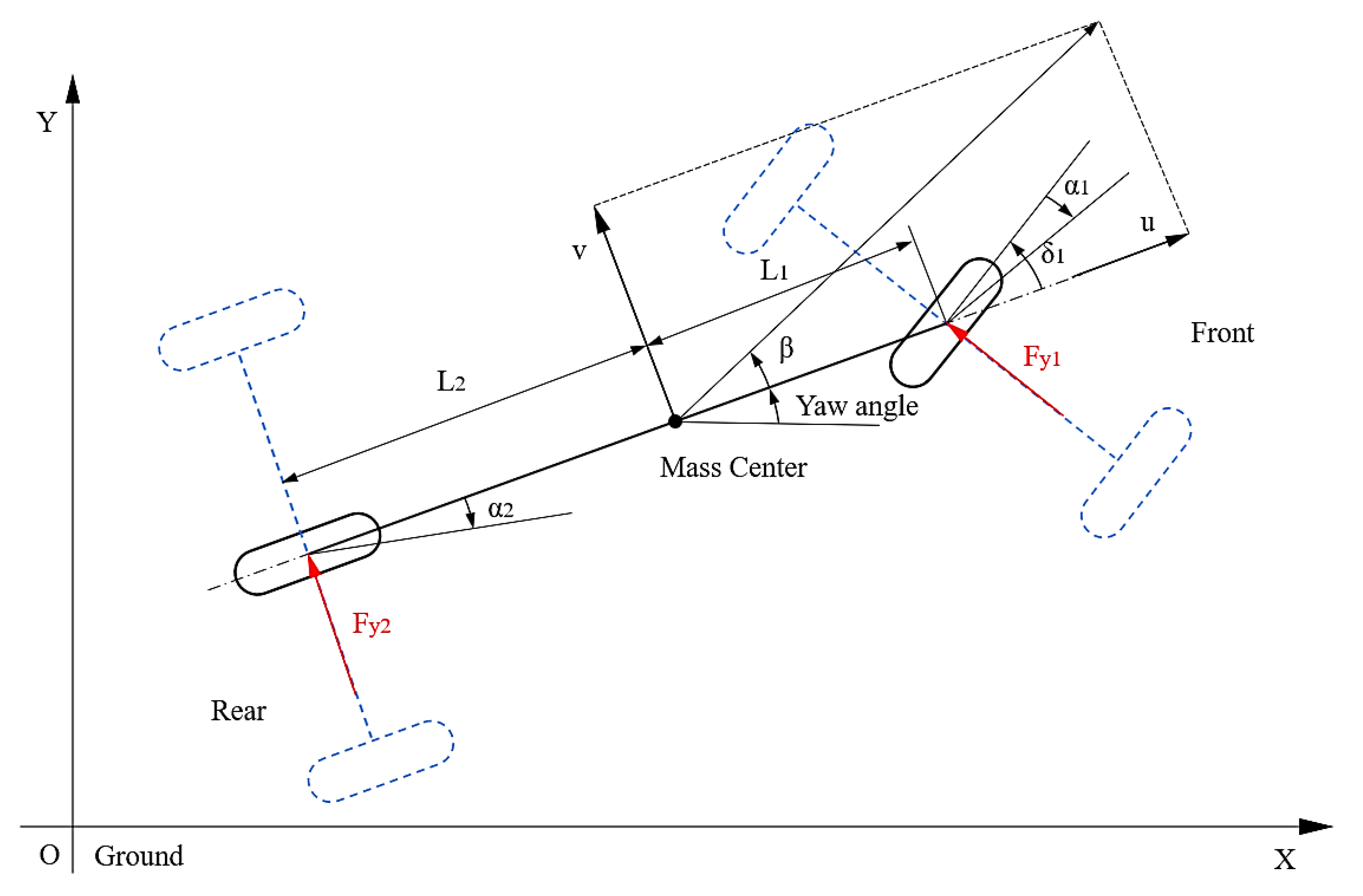
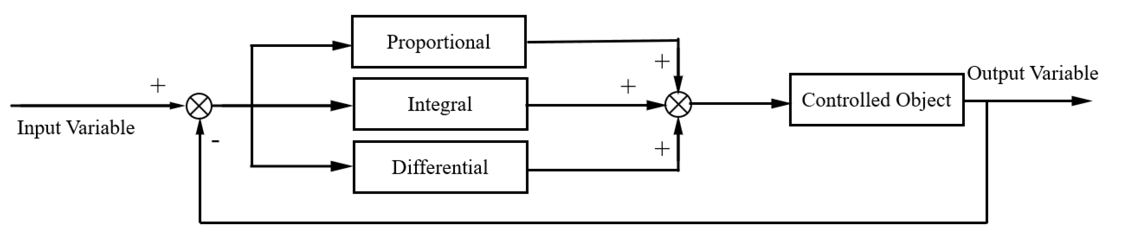
Section 2, the state space expression of lateral stability control is given by studying the control mechanism of the ESP. The ideal yaw angle rate and sideslip angle of the mass center are calculated by deriving the ideal monorail model with two degrees freedom. Finally, a direct yaw moment proportional–integral–differential (PID) control strategy based on yaw rate and centroid sideslip angle is proposed.
In Section 3, the multi-objective fuzzy continuous damping controller based on ESP is proposed to achieve sky-hook control and thereby ensure passenger comfort while preventing rollover. The effect of the ESP can be improved by redistributing the vertical force at the same time.
In Section 4 and Section 5, the effect of the multi-objective fuzzy continuous damping control strategy is analyzed and verified through a sine wave steer input test, double line change (DLC) test, and fishhook test. The simulation results show that the multi-objective fuzzy control strategy is successful. The strategy can ensure the comfort of passengers under good driving conditions while ensuring strong adaptability and control effect under dangerous and extreme working conditions.

2. Basic Handling Stability Control Strategy of ESP

VDM is a vehicle chassis integrated control system based on the ESP and CDC and other chassis control subsystems, such as the antilock braking system, traction control system, and even four-wheel steering system [35,36]. Direct yaw moment control (DYC) is a common way to handle stability control.

2.1. Construction of Direct Yaw Moment Controller

2.1.1. Linear Monorail Standard Equation with DYC

The stability of a vehicle when turning can be significantly improved by DYC, which is designed to boost vehicle stability. The basic idea of DYC is to change the ratio of the driving or braking force between the inner and outer wheels of a vehicle so as to make the vehicle produce an additional restoring yaw moment, which prevents the instability of the vehicle as much as possible.
The research and development of handling and stability systems is mainly completed by tracking the ideal vehicle model on the basis of the actual motion state of vehicles. However, the definition of an ideal vehicle model remains unclear. In the whole process of vehicle motion, numerous uncertain parameters affect the modeling accuracy of complex vehicle systems. Although the design of vehicle controllers is considerably difficult, the variations of bounded uncertain parameters make the whole vehicle system controllable. The linear monorail model of vehicle motion with two degrees of freedom includes several important parameters, such as body mass, yaw rate, sideslip angle, wheelbase, and lateral stiffness of the front and rear axles. Collectively, these parameters can reflect the lateral motion of vehicles. Therefore, such linear monorail model with two degrees of freedom is usually used as an ideal model for the design of stability control strategies, and its steering characteristics are considered as vehicle stability control objectives.
When the vehicle is regarded as a monorail model with two degrees of freedom (Figure 1), the following equilibrium relationships of the system dynamic force of the vehicle can be established as follows:
m t ( v ˙ + u r ) = F y 1 + F y 2
I z r ˙ = L 1 F y 1 L 2 F y 2
F y j = K α j α j
v 1 = v + L 1 r = u tan ( δ 1 α 1 )
v 2 = v L 2 r = u tan ( α 2 )
v u = tan β
where mt is the total mass of the vehicle; Fyj is the lateral force of each vehicle axle; u, v are the longitudinal and lateral speeds of the vehicle, respectively; r is the yaw angle rate of the vehicle; Kαj is the lateral slip stiffness of each axle; αj is the slip angle of each axle; vj is the longitudinal speed of each axle; Lj is the longitudinal distance from each axle to the mass center; δ1 is the front wheel angle; β is the sideslip angle of mass center; and subscript j indicates front axle (subscript 1) and rear axle (subscript 2).
When an angle such as αj, δ1, and β is considerably small, the tangent value is approximately equal to the angle radian value. Therefore, Equations (4) and (5) can be respectively simplified into the following:
α 1 = δ 1 v + L 1 r u
α 2 = v L 2 r u
By substituting Equations (3), (6)–(8) into Equations (1) and (2) and with the application of the DYC moment Mzd-ESP, the following are obtained:
u m t ( β ˙ + r ) = ( K α 1 + K α 2 ) β + 1 u ( L 1 K α 1 L 2 K α 2 ) r K α 1 δ 1
I z r ˙ = ( L 1 K α 1 L 2 K α 2 ) β + 1 u ( L 1 2 K α 1 + L 2 2 K α 2 ) r L 1 K α 1 δ 1 + M z d E S P
Equations (9) and (10) can be transformed into the following standard state space equation:
X ˙ = A X + B U
where state vector, input vector, and relevant matrix are:
X = ( β r ) T U = ( δ 1 M z d E S P ) T A = [ K α 1 + K α 2 u m t L 1 K α 1 L 2 K α 2 u 2 m t u 2 m t L 1 K α 1 L 2 K α 2 I z ( L 1 2 K α 1 + L 2 2 K α 2 ) u I z ] B = [ K α 1 u m t 0 L 1 K α 1 I z 1 I z ]

2.1.2. Control Target: Ideal Yaw Rate and Sideslip Angle of Mass Center

When no DYC control is added, the ideal vehicle should always be in a steady driving state. When the vehicle is in a steady state, the lateral acceleration and yaw angular acceleration are zero, and the differential term on the left side of Equations (9) and (10) disappears and becomes a solvable equation. The steady-state yaw rate gain and centroid sideslip angle gain can be obtained as
r d δ 1 ) s = u / ( L 1 + L 2 ) 1 + m t ( L 1 + L 2 ) 2 ( L 1 K α 2 L 2 K α 1 ) u 2 = u / ( L 1 + L 2 ) 1 + D u 2
β d δ 1 ) s = 1 ( L 1 + L 2 ) L 1 K α 1 ( L 1 + L 2 ) ( 1 + D u 2 ) ( L 1 2 K α 1 + L 2 2 K α 2 ) ( 1 + D u 2 ) ( L 1 K α 1 L 2 K α 2 )
where coefficient D is a stability factor, which is only related to the structure of the vehicle but is independent of the vehicle motion state. It is an important parameter in the study of vehicle steady-state response, and it can be expressed as
D = m t ( L 1 + L 2 ) 2 ( L 1 K α 2 L 2 K α 1 )
When the sideslip angle is very small, the ground adhesion constraint condition can be expressed as follows:
| u r d | | a y | μ g
β d μ g L 1 K α 1 u 2 δ 1 ( L 1 2 K α 1 + L 2 2 K α 2 ) u 2 ( L 1 K α 1 L 2 K α 2 )
where ay is the lateral acceleration of the vehicle; μ is the friction coefficient of the road; g is the gravity acceleration.
The ideal yaw rate and sideslip angle control targets with consideration of steady-state driving and adhesion conditions can be written as:
r d = min { | r d | , | r d | } = min { | u / ( L 1 + L 2 ) 1 + D u 2 δ 1 | , | μ g u | }
                                                                  β d = min { | β d | , | β d | } = min { | 1 ( L 1 + L 2 ) L 1 K α 1 ( L 1 + L 2 ) ( 1 + D u 2 ) ( L 1 2 K α 1 + L 2 2 K α 2 ) ( 1 + D u 2 ) ( L 1 K α 1 L 2 K α 2 ) δ 1 | , | μ g L 1 K α 1 u 2 δ 1 ( L 1 2 K α 1 + L 2 2 K α 2 ) u 2 ( L 1 K α 1 L 2 K α 2 ) | }

2.1.3. PID Control Strategy for DYC

Proportional–integral–differential (PID) control first appeared in all control strategies and thus was widely studied. It is also the most commonly used control law and is the embodiment of feedback theory. Given its simple algorithm, high reliability, and few setting parameters (i.e., proportional parameter P, integral parameter I, and differential parameter D), PID control is widely used in control systems.
The PID control principle is shown in Figure 2 and the ESP controller model is shown in Figure 3.

3. Design of Multi-Objective Fuzzy Continuous Damping Controller

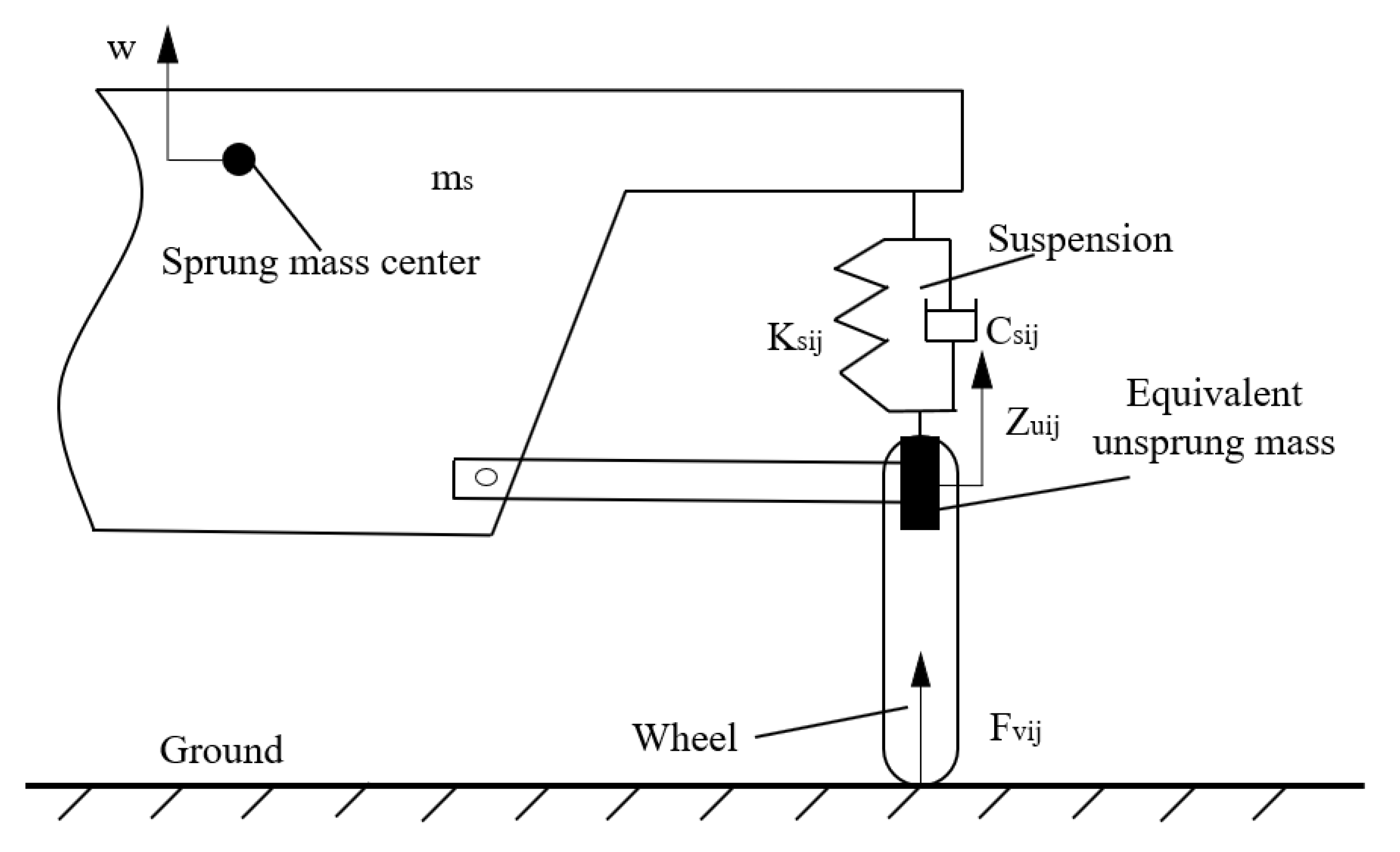
CDC suspension can guarantee the comfort of passengers under good level road conditions. The damping forces in the suspension can be changed through the control function of CDC suspension. This step can reduce the vehicle roll degree and change the vertical load distribution of the vehicle so as to aid the ESP. The vertical force on the suspension of each wheel can be expressed by the following equations, and the suspension model is shown in Figure 4.
F v l 1 = K s l 1 ( Z u l 1 Z s + L 1 sin θ + B 1 2 sin φ ) + C s l 1 ( Z u l 1 ˙ w + L 1 q cos θ + B 1 2 p cos φ )
F v l 2 = K s l 2 ( Z u l 2 Z s L 2 sin θ + B 2 2 sin φ ) + C s l 2 ( Z u l 2 ˙ w L 2 q cos θ + B 2 2 p cos φ )
F v r 1 = K s r 1 ( Z u r 1 Z s + L 1 sin θ B 1 2 sin φ ) + C s r 1 ( Z u r 1 ˙ w + L 1 q cos θ B 1 2 p cos φ )
F v r 2 = K s r 2 ( Z u r 2 Z s L 2 sin θ B 2 2 sin φ ) + C s r 2 ( Z u r 2 ˙ w L 2 q cos θ B 2 2 p cos φ )
where Fvij is the vertical force of each wheel; p, q are the roll angle rate and pitch angle rate of the vehicle, respectively; w is the vertical speed of the vehicle; φ, θ are the roll angle and pitch angle of the vehicle; Ksij, Kuij are the stiffness coefficients of spring and wheel of each wheel, respectively; Csij, Cuij are the damping coefficients of the shock absorber and wheel, respectively; Zuij is the unsprung mass displacement of each wheel; Bj is the wheel distance of each axle; subscript i (l or r) indicates the left or right side.
The DYC moment can be written as:
M z d E S P = ( F b l 1 F b r 1 ) B 1 + ( F b l 2 F b r 2 ) B 2
where Fbij is the braking force of each wheel (direction back is positive).
The braking force is constrained by the adhesion of the ground:
F b i j = ( μ F v i j ) 2 F y i j 2
where Fyij is the lateral force of each wheel.
The previous equations indicate that CDC can change the adhesion by changing the vertical force of the ground, thereby increasing the threshold range of the braking force.

3.1. Control Objectives and Strategies

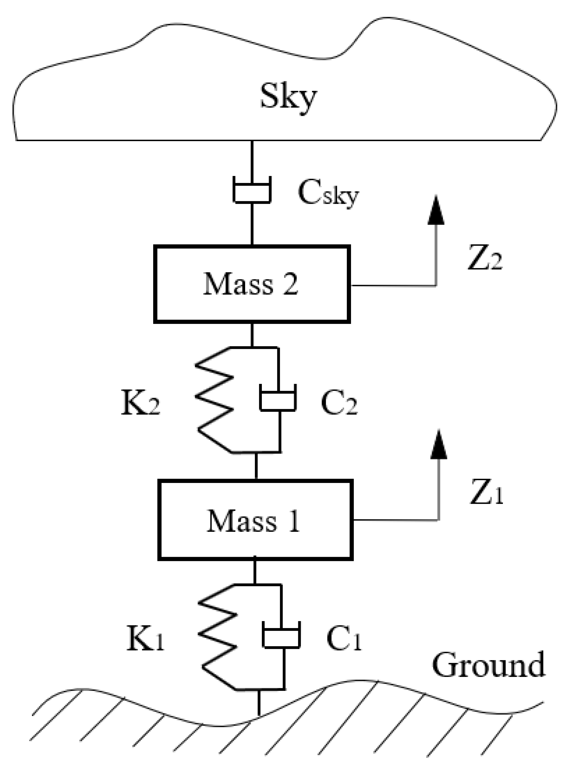
3.1.1. Sky-Hook Control

Sky-hook control assumes that two ends of the damper are not fixed between two masses; instead, it assumes that one end is fixed on one mass and that the other end is fixed in the sky. In this way, the sky-hook shock absorber does not have the opposite effect on both masses at the same time (Figure 5).
CDC is a semiactive suspension with real-time control of damping force. The power of the CDC shock absorber must be positive under the theory of semiactive suspension. Given the absence of an external energy injection in semiactive suspension, the form of CDC energy transfer can only be from mechanical energy into thermal energy; it can be written as
P D i j C D C = { F D i j C D C ( w Z u i j ˙ ) = C D i j C D C w ( w Z u i j ˙ ) , w ( w Z u i j ˙ ) > 0 0 , w ( w Z u i j ˙ ) 0
F D i j Sign ( Z D i j ˙ ) 0
where the function Sign(x) is described as:
Sign ( x ) = {         1 , x > 0     0 , x = 0 1 , x < 0
Z D i j ˙ = w Z u i j ˙
where PDij-CDC is the power of the CDC shock absorber of each wheel, FDij-CDC is the force of the CDC shock absorber of each wheel, CDij-roll is the damping coefficient of the CDC shock absorber of each wheel, ZDij is the displacement of the shock absorber of each wheel, and x is a variable.
Sky-hook damping control provides a damping force opposite to the sprung mass speed in real time. Hence, it can produce minimal spring mass vibration and ensure the comfort of passengers to the maximum extent.
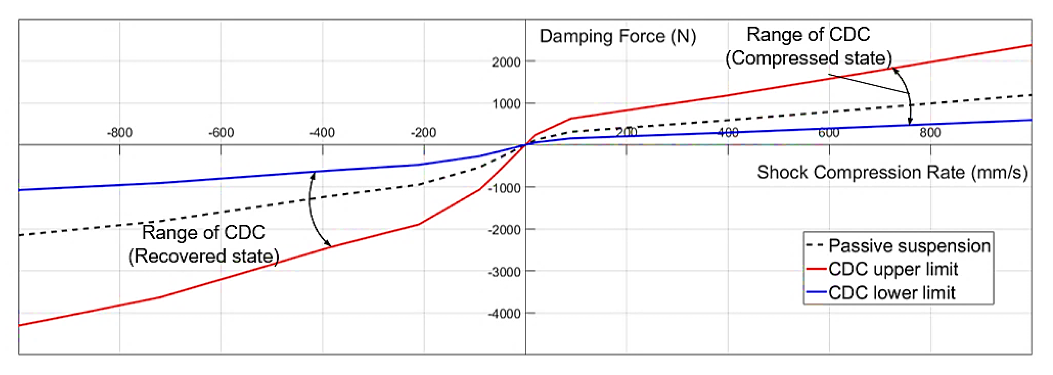
In addition to the fact that CDC has no external energy constraint, it is affected by its own external characteristics, and it has maximum and minimum damping force limits (Figure 6).

3.1.2. Antirollover Control

When a vehicle is rolling, its lateral load transfer ratio (LTR) can be expressed by the vertical force; it is given by [37]
L T R = F v l F v r F v l + F v r
{ F v l = F v l 1 + F v l 2 F v r = F v r 1 + F v r 2
LTR is an indicator of vehicle rollover risk and is defined as the proportion of the difference between the vertical load of the left and right wheels in the total vehicle mass. LTR varies from −1 to 1 regardless of the working condition of the vehicle. When the vehicle runs in a straight line, the vertical loads of the left and right wheels are the same, and the LTR is equal to 0. When the vehicle turns, the vertical force of one wheel transfers to the other side, and the LTR value gradually increases or decreases. When one side of the wheel is off the road, the LTR value reaches 1 or −1. This rollover evaluation method can achieve accurate rollover prediction when one side of the wheel leaves the ground at the same time.

3.2. Multi-Objective Fuzzy Continuous Damping Controller

Fuzzy control has a weak dependence on mathematical model, so it is widely used in uncertain or nonlinear control systems [38,39,40]. Compared with some traditional control techniques, it has a certain degree of intelligence and has strong robustness to parameter changes. In recent years, there are many researches on fuzzy control in the field of damping control [41,42,43]. A multi-objective fuzzy continuous damping controller is constructed to realize vehicle stability control under constraint control with stability and antirollover control.
The damping forces of the sky-hook damping control are calculated under any working condition. When other conditions requiring control arise, the force generated by fuzzy control is added to the damping force of sky-hook damping control.
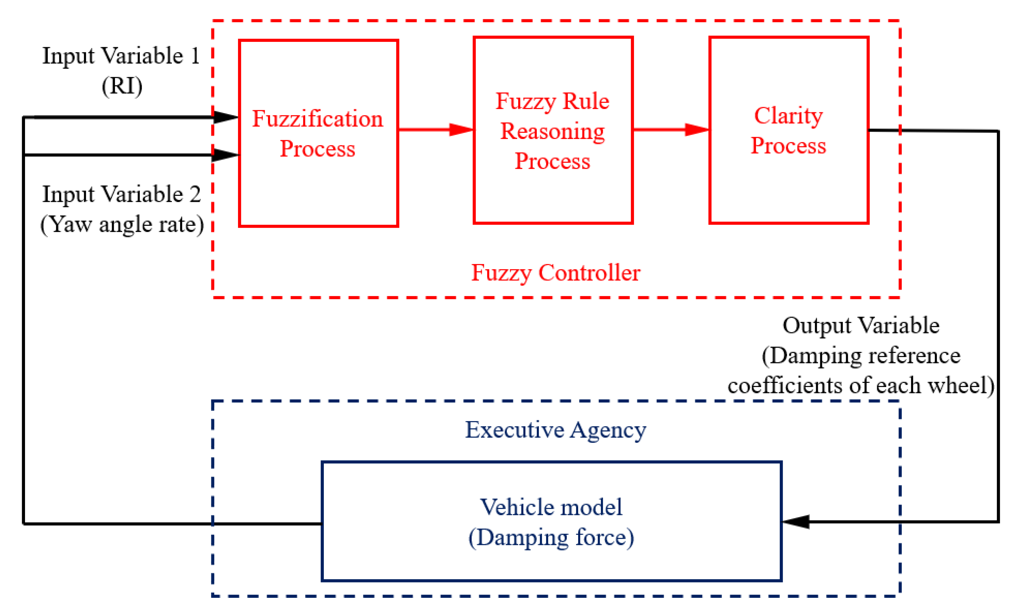
Fuzzy inference controller is mainly divided into three parts: fuzzification process, fuzzy rule reasoning process, and clarity process [44]. The fuzzy control structure of this work is shown in Figure 7.

3.2.1. Fuzzification Process

The main function of fuzzification is to process accurate variables and transform them into corresponding universe to form fuzzy variables.
The inputs of fuzzy control are rollover index (RI; i.e., the value of the LTR mentioned previously) and yaw angle rate. The outputs are the damping reference coefficients of each wheel that generates a corresponding damping force through PID control. The objective is to reduce the vibration of passengers under normal driving conditions and to achieve stability and rollover control in the case of rollover or instability.
The process of fuzzification needs to complete the operation of accurate clear quantity into fuzzy quantity. The fuzzy universe of each variable should be defined at first, which can realize the transformation from physical clarity to fuzziness by quantization factors. The fuzzy universe of RI is defined as [−1, +1], the fuzzy universe of yaw angle rate is defined as [−8, +8] and the fuzzy universes of the damping reference coefficients of each wheel are defined as [0, +1]. In order to correspond the actual variables to the normalized universe, the quantization factors are defined as NRI = 1, Nyaw = 8/|rmax|, Nu = 1.
Taking RI as an example, the fuzzy language variable is used to describe the input variable RI [45]. After fuzzifying, the fuzzy set T(RI) of the RI can be expressed as
T ( R I ) = { N e g a t i v e   B i g N e g a t i v e   S m a l l Z e r o P o s i t i v e   S m a l l P o s i t i v e   B i g }
It can be abbreviated as
T ( R I ) = { N B N S Z O P S P B }
Similarly, fuzzy sets of the yaw angle rate and the damping reference coefficient can be obtained.
The fuzzy set T(r) of the yaw angle rate can be expressed as
T ( r ) = { N B N M ( N e g a t i v e   M i d d l e ) N S Z O P S P M ( P o s i t i v e   M i d d l e ) P B }
The fuzzy set U(dc) of the damping reference coefficient of each wheel can be expressed as
U ( d c ) = { S S ( V e r y   S m a l l ) S ( S m a l l ) M ( M i d d l e ) B ( B i g ) B B ( V e r y   B i g ) }

3.2.2. Fuzzy Rule Reasoning Process

The triangular membership function is easy to operate on the premise of meeting the accuracy requirements and it is more conducive to simulation; the language variables are almost all triangular membership functions (NB and PB of the yaw angle rate are trapezoidal membership functions).
The expression of triangular membership function is
f ( x , a 1 , a 2 , a 3 ) = { 0 ,     x a 1 x a 1 a 2 a 1 ,     a 1 < x a 2 a 3 x a 3 a 3 ,     a 2 < x < a 3 0 ,     x a 3
where a2 is the vertex coordinate value of the triangle; a1 and a3 are the intersection coordinates of the left and right sides of the triangle and the bottom edge, respectively.
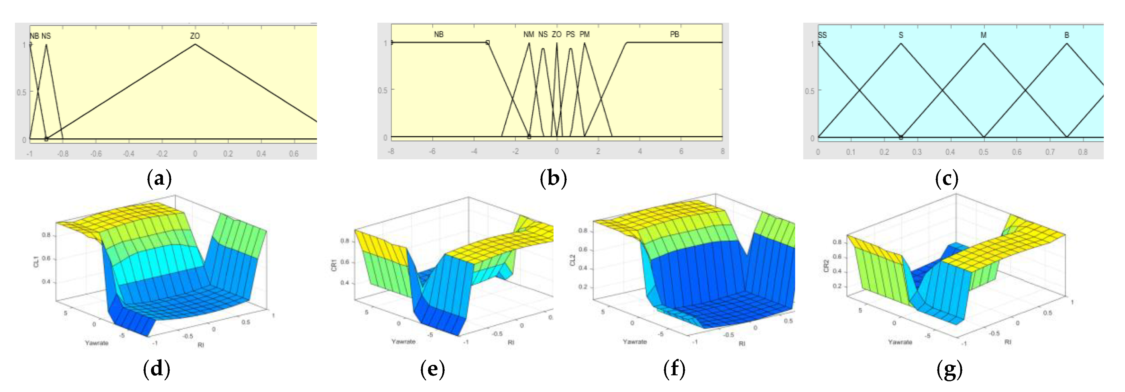
The input and output variables and the rules of fuzzy control are shown in Figure 8.
The basic idea of multi-objective fuzzy continuous damping control is described as follows. Under good road conditions (RI and yaw rate values are extremely small), the additional damping force generated by fuzzy control should be as small as possible to prevent any impact on sky-hook control. When the RI reaches a relatively large degree, the compressed and damping reaction should be increased to prevent excessive roll moment and thereby produce a damping force with a compensation effect to resist rollover. When the RI value is relatively small and the yaw rate is large, the prevention of instability should be the top consideration, and the ground adhesion should be increased by boosting the damping force of relevant wheels so as to aid the ESP in producing satisfactory effects. When the RI and yaw rate are large but show opposite effects (this state is rare and is generally caused by tripped rollover), a moderate damping force can be considered to build a certain complementary relationship between stability and rollover.
The fuzzy implication relation that consists of a series of “if… then…” is composed of linguistic fuzzy rules, which can be converted into tabular fuzzy rules [46]. The tabular fuzzy rules are intuitive, simple, and easy to check, which are often used in the design of fuzzy controllers. The fuzzy rule tables can be established as shown in the following Table 1, Table 2, Table 3 and Table 4 (CL1/CR1/CL2/CR2: damping reference coefficient of front left/front right/rear left/rear right wheel, respectively).

3.2.3. Clarity Process

After the fuzzy logic reasoning, the output conclusion is a fuzzy variable which cannot directly drive the actuator to control and needs to be changed into a clear variable. The process of transforming fuzzy variable into clear variable is called clarity. The method of calculating the curve of membership function of fuzzy set and the center of area surrounded by abscissa is centroid method [42]. The solution x0 and the mathematical expression of centroid method is as follows:
x 0 = x f ( x , a 1 , a 2 , a 3 ) d x f ( x , a 1 , a 2 , a 3 ) d x
The quantization factors are defined as Nu = 1. The actual damping forces of suspension are calculated by the range of CDC and the damping reference coefficients of fuzzy control.

4. Simulation and Result Analysis

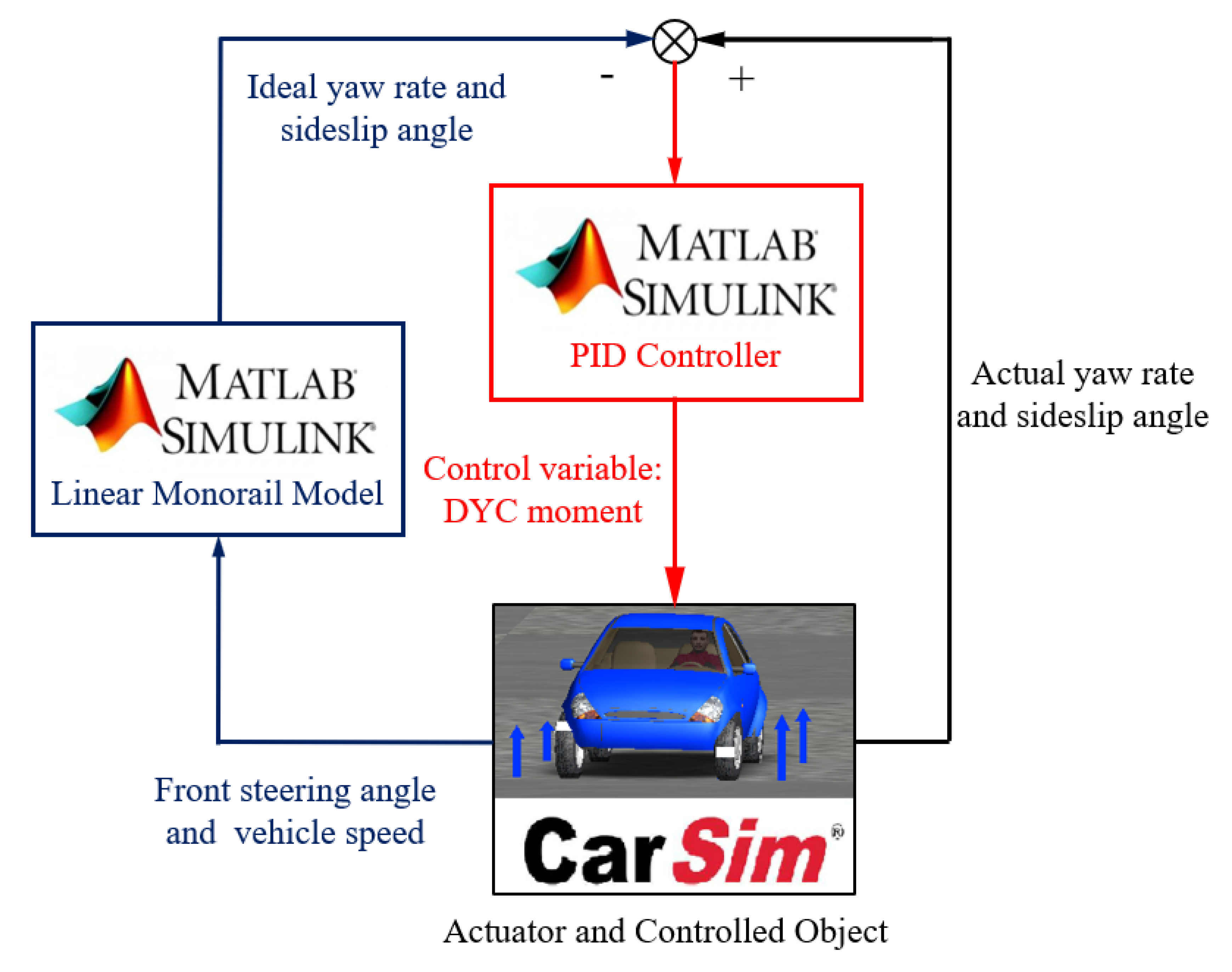
A real vehicle model is constructed in the software CarSim, and a control model is constructed in MATLAB/Simulink. The simulation analysis is performed through cosimulation in MATLAB/Simulink and CarSim. Passive suspension without any control (abbreviated as NC) and passive suspension with ESP (abbreviated as P-ESP) are compared with the multi-objective fuzzy continuous damping control strategy with ESP (abbreviated as MFCDC-ESP) to illustrate the effect. The main parameters of vehicle model and control model are shown in Table 5 and Table 6, respectively.
The real vehicle selected for the funding project is an A0 class high centroid vehicle. Although it has a high centroid, its mass is not large, and it is more prone to sideslip than to rollover in the absence of an ESC system when driving. Therefore, the selection of its parameters is the critical condition obtained via repeated simulations, and it can show the effect of vehicle control under the limited state.
To verify the MFCDC-ESP effect of stability and antirollover, this work compares and simulates three test conditions, namely, sine wave steer input test, DLC test, and fishhook test.

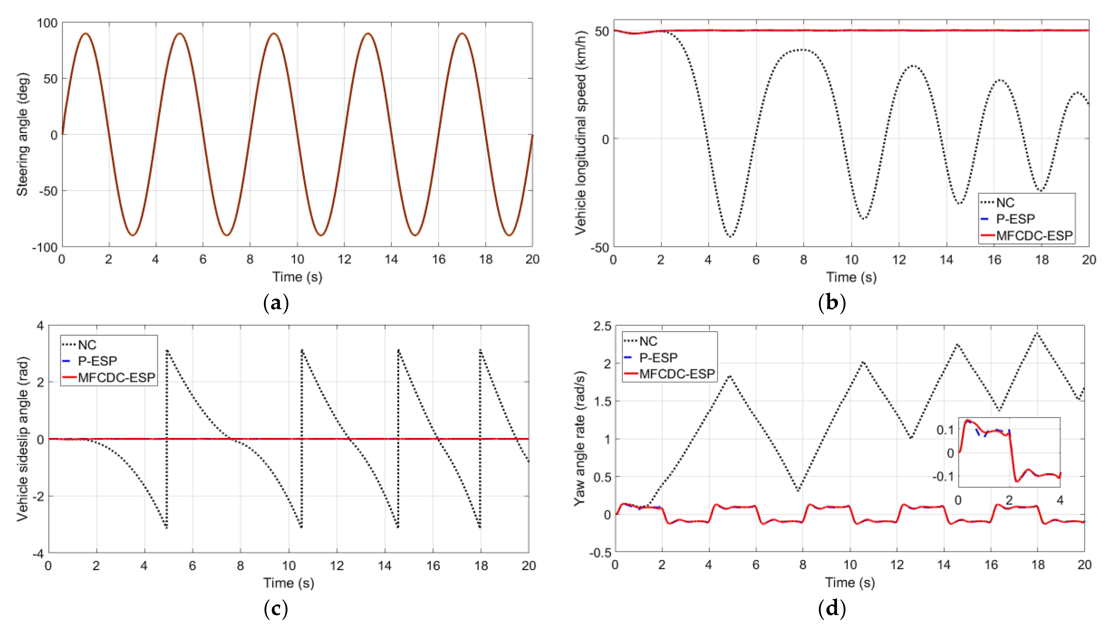
4.1. Sine Wave Steer Input Test

The sine wave steer input test is the most frequently used condition for verifying driver control stability. The basic parameters of the simulation analysis of the sine wave steer input test are shown in Table 7.
The results of simulation are shown in Figure 9.
As shown in Figure 9, the longitudinal speed of NC decreases rapidly at 2 s, and the sideslip angle of the mass center and the yaw angle rate increase at the same time. Then, violent vibration occurs, and the frequency of the oscillation cycle increases. In terms of vehicle speed, the speed of the vehicle with P-ESP and MFCDC-ESP is only slightly reduced at the beginning due to the respective effects of lateral force and braking force; then the vehicle maintains a stable target speed. With regard to the sideslip angle of the mass center and yaw rate, the range of variations is relatively small. These comparisons show that the vehicle without control loses stability and that the vehicles with P-ESP and MFCDC-ESP present a good control effect on vehicle stability.
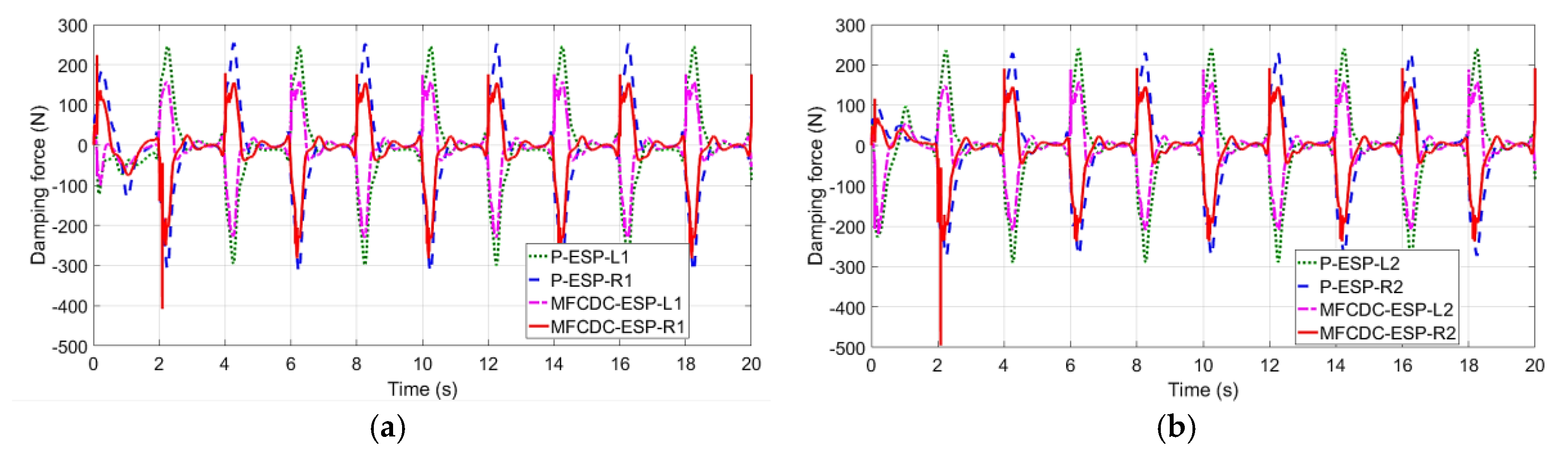
In illustrating the control effect of MFCDC-ESP, this work shows the vertical force and damping force in Figure 10 and the simulation data results in Table 8.
The average value of MFCDC-ESP’s yaw angle rate is far less than that of P-ESP in the whole control action (Figure 10 and Table 8). Hence, the whole vehicle is in a relatively stable state in the whole process of motion. As for the vertical force, the maximum vertical force of each wheel of MFCDC-ESP is greater than that of P-ESP while the minimum value of the former is less than that of the latter; the difference for the rear axle wheels is even greater. These results show that MFCDC-ESP can maximize the rear axle, which lacks lateral force, for stability control. From the point of view of the damping force of each wheel, the damping forces of the front and rear axles on the right side of MFCDC-ESP increase suddenly at about 2 s. As shown in Figure 8, the moment at 2 s is the critical moment of lateral stability control (the vehicle with NC suddenly becomes unstable around this moment). The compensation effect of MFCDC-ESP also makes the vehicle establish good dynamic control. The standard deviation of the damping force of MFCDC-ESP is much smaller than that of P-ESP because of the sky-hook control effect after the vehicle enters the stationary period. This result also shows that the force on the vehicle body is reduced and that the passengers experience enhanced comfort. In practical application, MFCDC-ESP can automatically identify and switch the state between stability and comfort in real time due to its fuzzy control characteristics, so as to achieve the best driving effect.

4.2. DLC Test

The DLC test is often used to measure the function effect of ESP. The DLC test in this work only compares P-ESP with MFCDC-ESP to show the superiority of the latter, especially given the result of the sine wave input test emphasizing that a vehicle without control can easily lose stability. The basic parameters of the DLC test simulation analysis are shown in Table 9.
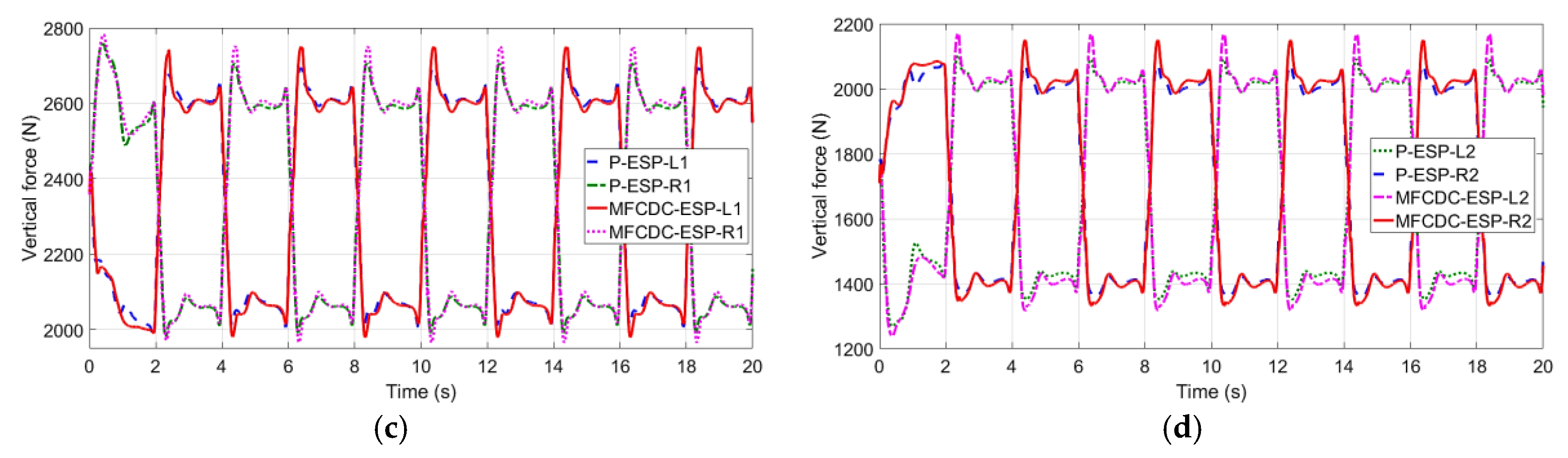
The results of the simulation are shown in Figure 11.
The simulation curve shows that the vehicle maintains good stability under the two control strategies because of the ESP. In comparison with those of P-ESP, the roll angle rate of MFCDC-ESP is smaller, and the comfort felt by passengers is better. Given the influence of the sky-hook control of MFCDC-ESP, the damping force of MFCDC-ESP is generally less than that of P-ESP when driving in a stable state. However, at 2.5 and 5.7 s, the damping force of MFCDC-ESP suddenly increases. Combined with the steering angle, these two positions are the critical moment for the change of the steering angle and are the most vulnerable periods for the vehicle to lose stability (this point of view can be also clearly reflected in the previous sine wave steer input test). Moreover, the vertical forces are redistributed. The rear axle with great braking potential undertakes heavy load distribution without lateral force; the same effect is desired for vehicle control. Therefore, the control strategy of MFCDC-ESP can change the distribution of vertical forces and quickly compensate for the occurrence of instability; it even exerts a certain predictive effect. In addition, CDC plays an important role in driving stability with auxiliary effects. The simulation data are reported in Table 10.

4.3. Fishhook Test

The fishhook test is used to verify the effect of MFCDC-ESP on rollover. The basic parameters of the fishhook test simulation analysis are shown in Table 11.
The main parameters of the fishhook test simulation are shown in
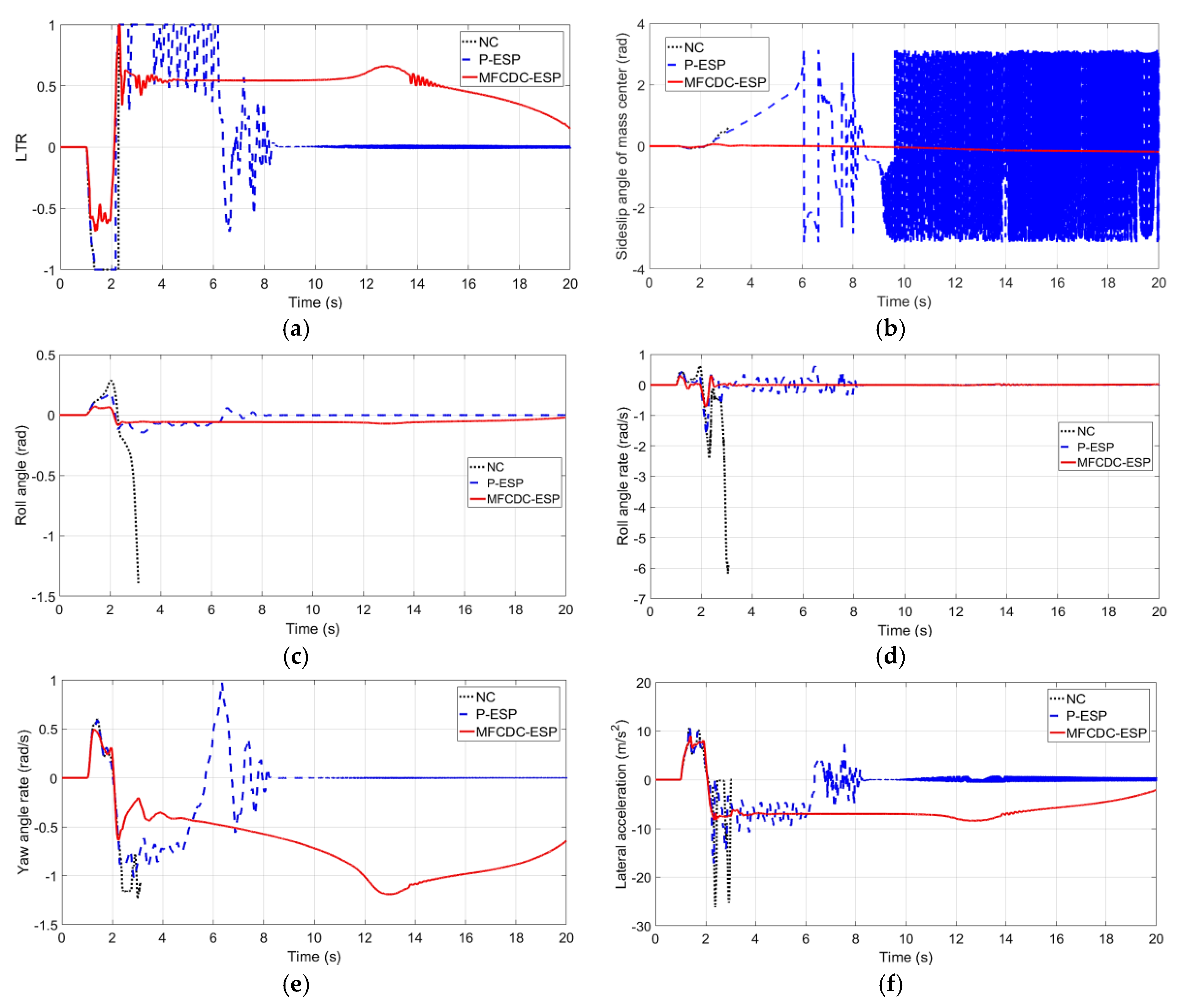
 Figure 12.
The LTR of the NC vehicle has a step at 3 s, with the roll angle and roll angle rate increasing sharply and resulting in serious rollover. Despite the many cases in which one side wheel is off the ground (LTR reaches 1 or −1), no rollover occurs with P-ESP. The main reason is that the lateral acceleration of the vehicle is reduced due to the action of the ESP. From the yaw angle rate and sideslip angle of the mass center, the whole vehicle vibrates from 6 s to 8 s. Although the yaw angle rate is controlled in a small range after 8 s, the continuous oscillation of the side slip angle of the mass center indicates that the vehicle has entered an unstable state. The vehicle with MFCDC-ESP has no instability phenomenon in the whole movement process, and all parameters are within the controllable range. Because the damping forces of CDC are controlled by electrical signal, the sudden changes of damping forces often lead to the sudden change of control current. The damping force current signal can be collected and identified by appropriate methods, and the driver can be given a corresponding real-time rollover warning, which improves the rollover prediction effect.

5. Conclusions

The theoretical analysis and test results reveal that the vehicle with ESP can realize control over handling stability and that CDC can greatly improve the comfort of passengers under the action of sky-hook control. MFCDC-ESP combines these two functions organically and optimizes ride comfort. The control effect of the ESP can be improved, and extremely dangerous conditions can be effectively prevented when rollover occurs with MFCDC-ESP through the redistribution of the vertical force.
MFCDC-ESP is superior to P-ESP in terms of ride comfort from the quantitative point of view; it also has an obviously different damping force and roll angle. In terms of stability control, MFCDC-ESP can effectively use the rear axle for load redistribution; the rear axle has a certain auxiliary lifting effect on the ESP. MFCDC-ESP has a significant advantage in preventing rollover (because P-ESP has no control strategy to inhibit rolling). Moreover, MFCDC-ESP has strong real-time sensitivity to the control state of the damping force of each wheel. MFCDC-ESP can maintain the optimized distribution of damping forces through its own compensation in the case of possible instability. it can even predict the critical stable state to some extent.
In general, MFCDC-ESP vehicles can ensure the comfort of passengers under good driving conditions while having strong adaptability and control effect under various extreme working conditions. MFCDC-ESP perfectly meets the requirements of comfort, handling stability, and rollover prevention. In practical engineering simulation and application, fuzzy control can use human expert control experience to realize process automatic control for nonlinear and complex objects. Fuzzy control has a certain ability to judge and deal with uncertainty and it can realize the design of vehicle control systems which have a certain degree of intelligence.

Author Contributions

X.Z. conceived the control method, completed the modeling, analyzed the results, and finished the manuscript. C.S. provided overall guidance for the study and managed the project. S.S. and D.W. collected the data, reviewed, and revised the paper. J.C. and F.X. give crucial suggestions about fuzzy continuous damping force control strategy and perform simulation experiments. S.P. and C.Q. put forward the idea and debugged the model in MATLAB/Simulink. All authors have read and agreed to the published version of the manuscript.

Funding

This research is supported by the Science and Technology Development Plan Program of Jilin Province (Grant No. 20200401112GX) and Industry Independent Innovation Ability Special Fund Project of Jilin Province (Grant No. 2020C021-3).

Conflicts of Interest

The authors declare no conflict of interest.

References

  1. Reimpell, J.; Stoll, H.; Betzler, J.W. The Automotive Chassis: Engineering Principles, 2nd ed.; Soc. Automot. Eng.: Warrendale, PA, USA, 2001; pp. 286–419. [Google Scholar]
  2. He, J.; Crolla, D.A.; Levesley, M.C.; Manning, W. Coordination of active steering, driveline, and braking for integrated vehicle dynamics control. Proc. Inst. Mech. Eng. Part D J. Automob. Eng. 2006, 220, 1401–1421. [Google Scholar] [CrossRef]
  3. Ono, E.; Hattori, Y.; Muragishi, Y. Vehicle Dynamics Integrated Control for Four-wheel-distributed Steering and Four-wheel-distributed Traction/Braking Systems. Veh. Syst. Dyn. 2006, 44, 139–151. [Google Scholar] [CrossRef]
  4. Wang, J.; Longoria, R.G. Coordinated Vehicle Dynamics Control with Control Distribution. In Proceedings of the American Control Conference, Minneapolis, MN, USA, 14–16 June 2006; pp. 5348–5353. [Google Scholar]
  5. Roshanbin, A.; Naraghi, M. Vehicle Integrated Control-An Adaptive Optimal Approach to Distribution of Tire Forces. In Proceedings of the 2008 IEEE International Conference on Networking, Sensing and Control, Sanya, China, 6–8 April 2008; pp. 885–890. [Google Scholar]
  6. Hwang, T.H.; Park, K.; Heo, S.-J.; Lee, S.H.; Lee, J.C. Design of integrated chassis control logic for AFS and ESP. Int. J. Automot. Technol. 2008, 9, 17–27. [Google Scholar] [CrossRef]
  7. Lam, T.L.; Xu, Y.; Xu, G. Traction Force Distribution on Omni-directional Four Wheel Independent Drive Electric Vehicle. In Proceedings of the 2009 IEEE International Conference on Robotics and Automation, Kobe, Japan, 12–17 May 2009; pp. 3724–3729. [Google Scholar]
  8. Lam, T.L.; Qian, H.; Xu, Y.; Xu, G. Omni-directional Steer-by-wire Interface for Wheel Independent Steering Vehicle. In Proceedings of the 2009 IEEE International Conference on Robotics and Automation, Kobe, Japan, 12–17 May 2009; pp. 1383–1388. [Google Scholar]
  9. Tjonnas, J.; Johansen, T.A. Stabilization of Automotive Vehicles Using Active Steering and Adaptive Brake Control Allocation. IEEE Trans. Control. Syst. Technol. 2010, 18, 545–558. [Google Scholar] [CrossRef] [Green Version]
  10. Elmarakbi, A.; Rengaraj, C.; Wheately, A.; Elkady, M. New integrated chassis control systems for vehicle handling performance enhancement. Int. J. Dyn. Control 2013, 1, 360–384. [Google Scholar] [CrossRef] [Green Version]
  11. Her, H.; Koh, Y.; Joa, E.; Yi, K.; Kim, K. An Integrated Control of Differential Braking, Front/Rear Traction, and Active Roll Moment for Limit Handling Performance. IEEE Trans. Veh. Technol. 2016, 65, 4288–4300. [Google Scholar] [CrossRef]
  12. Her, H.; Suh, J.; Yi, K. Integrated control of the differential braking, the suspension damping force and the active roll moment for improvement in the agility and the stability. Proc. Inst. Mech. Eng. Part D J. Automob. Eng. 2015, 229, 1145–1157. [Google Scholar] [CrossRef]
  13. Yim, S. Coordinated control with electronic stability control and active steering devices. J. Mech. Sci. Technol. 2015, 29, 5409–5416. [Google Scholar] [CrossRef]
  14. Yi, K.; Song, B. A New Adaptive Sky-Hook Control of Vehicle Semi-Active Suspensions. Proc. Inst. Mech. Eng. Part D J. Automob. Eng. 1999, 213, 293–303. [Google Scholar] [CrossRef]
  15. Nugroho, P.W.; Li, W.; Du, H.; Alici, G.; Yang, J. An Adaptive Neuro Fuzzy Hybrid Control Strategy for a Semiactive Suspension with Magneto Rheological Damper. Adv. Mech. Eng. 2015, 6, 487312. [Google Scholar] [CrossRef]
  16. Poussot-Vassal, C.; Spelta, C.; Sename, O.; Savaresi, S.M.; Dugard, L. Survey and Performance Evaluation on Some Automotive Semi-Active Suspension Control Methods: A Comparative Study on A Single-Corner Model. Annu. Rev. Control. 2012, 36, 148–160. [Google Scholar] [CrossRef] [Green Version]
  17. Savaresi, S.M.; Poussot-Vassal, C.; Spelta, C.; Sename, O.; Dugard, L. Semi-Active Suspension Control Design for Vehicles, 1st ed.; Elsevier Scopus: Oxford, UK, 2010; pp. 15–40. [Google Scholar]
  18. Tseng, H.E.; Hrovat, D. State of the Art Survey: Active and Semi-Active Suspension Control. Veh. Syst. Dyn. 2015, 53, 1–29. [Google Scholar] [CrossRef]
  19. Valášek, M.; Novak, M.; Šika, Z.; Vaculin, O. Extended Ground-Hook-New Concept of Semi-Active Control of Truck’s Suspension. Vehicle System Dynamics. 1997, 27, 289–303. [Google Scholar] [CrossRef]
  20. Guglielmino, E.; Sireteanu, T.; Stammers, C.W.; Ghita, G.; Giuclea, M.; Casey, T. Semi-Active Suspension Control: Improved Vehicle Ride and Road Friendliness, 1st ed.; Copyr. Elsevier B.V. Scopus Springer-Verlag London Limited: London, UK, 2008; pp. 1–10. [Google Scholar]
  21. Altet, O.; Moreau, X.; Moze, M.; Lanusse, P.; Oustaloup, A. Principle and Synthesis of Hydractive CRONE Suspension. Nonlinear Dyn. 2004, 38, 435–459. [Google Scholar] [CrossRef]
  22. Harada, M.; Harada, H. Analysis of lateral stability with integrated contro1 of suspension and steering systems. JSAE Rev. 1999, 20, 465–470. [Google Scholar] [CrossRef]
  23. Yoshimura, T.; Emoto, Y. Steering And Suspension System Of A Full Car Model Using Fuzzy Reasoning Based On Single Input Rule Modules. Int. J. Veh. Auton. Syst. 2003, 1, 237–255. [Google Scholar] [CrossRef]
  24. Gaspar, P.; Szaszi, I.; Bokor, J. Design of robust controllers for active vehicle suspension using the mixed μ synthesis. Veh. Syst. Dyn. 2003, 40, 193–228. [Google Scholar] [CrossRef]
  25. Fan, Y.; Daofei, L. Review on Integrated Vehicle Dynamics Control. Trans. Chin. Soc. Agric. Mach. 2008, 6, 1–7. [Google Scholar]
  26. Sankaranarayanan, V.; Emekli, M.; Gilvenc, B.; Guvenc, L.; Ozturk, E.; Ersolmaz, E.; Eyol, I.; Sinal, M. Semiactive Suspension Control of A Light Commercial Vehicle. IEEE/ASME Trans. Mechatron. 2008, 13, 598–604. [Google Scholar] [CrossRef]
  27. Yoon, J.; Kim, D.; Yi, K. Design of a rollover index-based vehicle stability control scheme. Veh. Syst. Dyn. 2007, 45, 459–475. [Google Scholar] [CrossRef]
  28. Yoon, J.; Cho, W.; Koo, B.; Yi, K. Unified Chassis Control for Rollover Prevention and Lateral Stability. IEEE Trans. Veh. Technol. 2009, 58, 596–609. [Google Scholar] [CrossRef]
  29. Kangwon, L.; Youngwoo, K.; Jinhee, J. A study of integrated chassis control Algorithm with Brake Control and Suspension Control Systems for vehicle stability and handling performance. In Proceedings of the 2009 ICCAS-SICE, Fukuoka, Japan, 18–21 August 2009; pp. 4053–4057. [Google Scholar]
  30. Lu, S.-B.; Choi, S.-B.; Li, Y.-N.; Seong, M.-S.; Han, J.-S. Global Integrated Control of Vehicle Suspension and Chassis Key Subsystems. Proc. Inst. Mech. Eng. Part D J. Automob. Eng. 2010, 224, 423–441. [Google Scholar] [CrossRef]
  31. Lu, S.-B.; Li, Y.-N.; Choi, S.B. Contribution of chassis key subsystems to rollover stability control. Proc. Inst. Mech. Eng. Part D J. Automob. Eng. 2012, 226, 479–493. [Google Scholar] [CrossRef]
  32. Zhang, X.; Yu, W.; Ma, F.; Zhao, F.; Guo, K. Semi-Active Suspension Adaptive Control Strategy Based on Hybrid Control. Lect. Notes Electr. Eng. 2013, 195, 625–632. [Google Scholar]
  33. Her, H.; Yi, K.; Suh, J.; Kim, C. Development of Integrated Control of Electronic Stability Control, Continuous Damping Control and Active Anti-Roll Bar for Vehicle Yaw Stability. IFAC Proc. Vol. 2013, 7, 83–88. [Google Scholar] [CrossRef]
  34. Zulkarnain, N.; Zamzuri, H.; Mazlan, S.A. LQG Control Design for Vehicle Active Anti-Roll Bar System. Appl. Mech. Mater. 2014, 663, 146–151. [Google Scholar] [CrossRef]
  35. Ghoneim, Y.A.; Lin, W.C.; Sidlosky, D.M.; Chen, H.H.; Chin, Y.-K.; Tedrake, M.J. Integrated chassis control system to enhance vehicle stability. Int. J. Veh. Des. 2000, 23, 124–144. [Google Scholar] [CrossRef]
  36. Hac, A.; Bodie, M.O. Improvements in Vehicle Handling Through Integrated Control of Chassis System. Int. J. Veh. Des. 2002, 29, 23–50. [Google Scholar] [CrossRef]
  37. Goldman, R.; El-Gindy, M.; Kulakowski, B. Rollover dynamics of road vehicles: Literature survey. Int. J. Heavy Veh. Syst. 2001, 8, 103–141. [Google Scholar] [CrossRef]
  38. Wang, Y.; Wang, R.; Xie, X.; Zhang, H. Observer-based H∞ fuzzy control for modified repetitive control systems. Neurocomputing 2018, 286, 141–149. [Google Scholar] [CrossRef]
  39. Mirzajani, S.; Aghababa, M.P.; Heydari, A. Adaptive T–S fuzzy control design for fractional-order systems with parametric uncertainty and input constraint. Fuzzy Sets Syst. 2019, 365, 22–39. [Google Scholar] [CrossRef]
  40. Pan, Y.; Yang, G.-H. Event-triggered fuzzy control for nonlinear networked control systems. Fuzzy Sets Syst. 2017, 329, 91–107. [Google Scholar] [CrossRef]
  41. Sajedi, P.D.; Behbahani, S. Semi-active fuzzy control of machine tool chatter vibration using smart MR dampers. Int. J. Adv. Manuf. Technol. 2016, 83, 421–428. [Google Scholar] [CrossRef]
  42. Askari, M.; Li, J.; Samali, B.; Gu, X. Experimental forward and inverse modelling of magnetorheological dampers using an optimal Takagi-Sugeno-Kang fuzzy scheme. J. Intell. Mater. Syst. Struct. 2016, 27, 904–914. [Google Scholar] [CrossRef]
  43. Li, B.; Zhao, W.; Wang, S.; Huang, H. Dynamic modeling and control for a five-dimensional hybrid vibration isolator based on a position/orientation decoupled parallel mechanism. J. Vib. Control. 2016, 22, 3368–3383. [Google Scholar] [CrossRef]
  44. Guo, Y.L.; Li, J.Y. Chapter 4 Fuzzy logic control theory. In Neural, Fuzzy, Predictive Control and Its MATLAB Implementation, 4th ed.; Publishing House of Electronics Industry: Beijing, China, 2018; pp. 187–222. [Google Scholar]
  45. Ejaz, M.; Chen, M. Fuzzy Optimal Control Design for Ship Steering. Trans. Nanjing Univ. Aeronaut. Astronaut. 2019, 36, 459–467. [Google Scholar]
  46. Feng, S.; Wu, H.-N. Robust adaptive fuzzy control for a class of nonlinear coupled ODE–beam systems with boundary uncertainty. Fuzzy Sets Syst. 2018, 344, 27–50. [Google Scholar] [CrossRef]
Figure 1. Monorail model with two degrees of freedom. The two wheels on the axle indicated by the blue dotted line are replaced by a monorail equivalent to the black solid line in this model.
Applsci 10 07923 g001
Figure 2. Proportional–integral–differential (PID) control principle.
Applsci 10 07923 g002
Figure 3. Electronic stability program (ESP) controller model. According to the monorail model with two degrees of freedom, the ideal values of yaw rate and mass sideslip angle of the ESP control system are generated, and the difference is calculated with the actual measured yaw rate and the center of the mass sideslip angle. PID control is carried out to output the difference of the left and right wheel moments.
Applsci 10 07923 g003
Figure 4. Suspension model. The unsprung mass of the suspension components and wheels is replaced by the equivalent unsprung mass in this model.
Applsci 10 07923 g004
Figure 5. Abridged general view of sky-hook control.
Applsci 10 07923 g005
Figure 6. Range of variation of CDC damping force.
Applsci 10 07923 g006
Figure 7. Multi-objective fuzzy continuous damping control structure.
Applsci 10 07923 g007
Figure 8. Multi-objective fuzzy continuous damping control model. (ac) are diagrams of the membership functions of the inputs RI and yaw rate and the output damping reference coefficient, respectively. (dg) are the diagrams of the rule surface of each wheel (CL1/CR1/CL2/CR2: damping reference coefficient of front left/front right/rear left/rear right wheel, respectively).
Applsci 10 07923 g008
Figure 9. Steering angle, vehicle longitudinal speed, vehicle sideslip angle, and yaw angle rate of sine wave steer input test. The result of NC is expressed with a black dotted line; the result of P-ESP is expressed with a blue chain line; the result of MFCDC-ESP is expressed with a red solid line. (a) is the steer angle input of the simulation. (bd) are the comparisons of the vehicle longitudinal speed, vehicle sideslip angle, and yaw angle rate, respectively.
Applsci 10 07923 g009
Figure 10. Damping forces and vertical forces of each wheel of the sine wave steer input test with P-ESP and MFCDC-ESP. The details are available in the legend. L denotes left, R denotes right, 1 denotes the front axle, and 2 denotes the rear axle. (a) is the comparison of the damping forces of the front wheels. (b) is the comparison of the damping forces of the rear wheels. (c) is the comparison of the vertical forces of the front wheels. (d) is the comparison of the vertical forces of the rear wheels.
Applsci 10 07923 g010aApplsci 10 07923 g010b
Figure 11. Simulation results of DLC test. (ad) are the comparison results of the steering angle, vehicle longitudinal speed, yaw angle rate, and roll angle rate, respectively. The damping forces and vertical forces of each wheel of the DLC test with P-ESP and MFCDC-ESP. (e) is the comparison of the damping forces of the front wheels. (f) is the comparison of the damping forces of the rear wheels. (g) is the comparison of the vertical forces of the front wheels. (h) is the comparison of the vertical forces of the rear wheels. The details are available in the legend. L denotes left, R denotes right, 1 denotes the front axle, and 2 denotes the rear axle.
Applsci 10 07923 g011
Figure 12. Main results of fishhook test. The result of NC is expressed with a black dotted line; the result of P-ESP is expressed with a blue chain line; the result of MFCDC-ESP is expressed with a red solid line. (af) are the comparison for LTR, vehicle sideslip angle, roll angle, roll angle rate, yaw angle rate, and lateral acceleration, respectively.
Applsci 10 07923 g012
Table 1. Fuzzy rule: RI, yaw angle rate and damping reference coefficient of front left wheel.
Yaw RateNBNMNSZOPSPMPB
CL1
RI
NBSSSSMBBBBBBBB
NSSSBBBBBBBB
ZOSSSSMBBB
PSBBBBBSS
PBBBBBBBBBMSS
Table 2. Fuzzy rule: RI, yaw angle rate and damping reference coefficient of front right wheel.
Yaw RateNBNMNSZOPSPMPB
CR1
RI
NBSSSSMBBBBBBBB
NSSSBBBBB
ZOBBBMSSSS
PSBBBBBBBBSS
PBBBBBBBBBMSS
Table 3. Fuzzy rule: RI, yaw angle rate and damping reference coefficient of rear left wheel.
Yaw RateNBNMNSZOPSPMPB
CL2
RI
NBSSMBBBBBBBB
NSSSBBBBBBBB
ZOSSSSSSSSMBBB
PSBBBBBSS
PBBBBBBBBBMSS
Table 4. Fuzzy rule: RI, yaw angle rate and damping reference coefficient of rear right wheel.
Yaw RateNBNMNSZOPSPMPB
CR2
RI
NBSSMBBBBBBBB
NSSSBBBBB
ZOBBBMSSSSSSSS
PSBBBBBBBBSS
PBBBBBBBBBMSS
Table 5. Main parameters of vehicle model.
Vehicle ParametersValueUnit
mt900kg
Iz708Kg m2
L1970mm
L2903mm
g9.8m/s2
Kα1144,000N/rad
Kα2312,000N/rad
Table 6. Main parameters of PID control model of ESP.
Vehicle ParametersValue
P-yaw angle rate150
I-yaw angle rate0.05
D-yaw angle rate2
P-sideslip angle10
I-sideslip angle0.1
D-sideslip angle2
Table 7. Main parameters of sine wave steer input test.
Test ParametersValueUnit
Longitude target speed50km/h
Friction coefficient0.16-
Steer input angle peak value90deg
Simulation time20second
Table 8. Main comparison results for the sine wave steer input test (P-ESP, MFCDC-ESP).
Test Results (Unit)P-ESPMFCDC-ESPPercentage Point 1
Yaw angle rate (rad/s)average−0.001353−0.00008605−93.64%
Vertical force L1 (N)maximum269427492.04%
minimum198019800%
Vertical force R1 (N)maximum275827820.87%
minimum19811966−0.76%
Vertical force L2 (N)maximum210321703.19%
minimum12681239−2.29%
Vertical force R2 (N)maximum209121502.82%
minimum13571332−1.84%
Damping force L1 (N)maximum245.7176.2−28.29%
minimum−299.3−230.3−23.05%
standard deviation93.7765.56−30.08%
Damping force R1 (N)maximum253.7223.8−11.79%
minimum−315.3−407.829.34%
standard deviation98.6570.42−28.62%
Damping force L2 (N)maximum239.3188.8−21.10%
minimum−289.8−219.2−24.36%
standard deviation93.8765.12−30.63%
Damping force R2 (N)maximum229.5192.2−16.25%
minimum−273.4−495.181.09%
standard deviation91.3165.02−28.79%
1 Percentage point = [(MFCDC-ESP’s data)-(P-ESP’s data)]/(P-ESP’s data) × 100%.
Table 9. Main parameters of DLC test.
Test ParametersValueUnit
Longitude target speed120km/h
Friction coefficient0.6-
Steer input angle peak value90deg
Table 10. Main comparison results of DLC test (P-ESP, MFCDC-ESP).
Test Results (Unit)P-ESPMFCDC-ESPPercentage Point
Yaw angle rate (rad/s)absolute maximum0.22660.2059−9.14%
standard deviation0.11990.1158−3.42%
Roll angle rate (rad/s)absolute maximum0.38960.357−8.37%
standard deviation0.096990.09082−6.36%
Vertical force L1 (N)absolute maximum334433680.72%
Vertical force R1 (N)absolute maximum35183508−0.28%
Vertical force L2 (N)absolute maximum296030181.96%
Vertical force R2 (N)absolute maximum313531721.18%
Table 11. Main parameters of fishhook test.
Test ParametersValueUnit
Longitude target speed80km/h
Friction coefficient0.85-
Steer input angle peak value294deg
Simulation time20second
Road conditionstraight-
Publisher’s Note: MDPI stays neutral with regard to jurisdictional claims in published maps and institutional affiliations.

