1. Introduction
Electro-mobility of public transport in cities has become an important issue in recent years, since passenger and freight transport consume more than a quarter of global primary energy and is responsible for significant greenhouse emissions [
1,
2]. Trolleybuses are commonly perceived as a valuable alternative to conventional buses in sustainable urban transportation systems [
3,
4,
5,
6]. However, the very presence of sliding current-carrying contact zone causes non-trivial problems. The traction brushes made of a mixture of graphite and copper filings have to be replaced on a weekly basis under standard operating conditions, because of their wear [
7].
The issue of how to assure a proper electric contact has been the subject of numerous research works and monographs [
8,
9,
10,
11]. It should be stressed that the problem is extremely complex, taking into account the roughness of the contacting surfaces, random occurrence of contact spots, elastic and plastic deformations, the presence of dirt, grease, soot burnouts, as well as possible vibrations of the pantograph-catenary system. The interdisciplinary nature of the problem attracts researchers on materials science and tribology, physicists, and mechanical and electrical engineers.
Senouci and colleagues [
7] focused on anisotropic electrical and mechanical properties of graphite. The authors have noticed that the friction and wear behavior of copper-graphite are influenced by the magnitude of electrical current. The authors have also examined the effect of contact polarity on the surfaces of contact, on the transferred layers, on the contact electrical potential and on the contact wear.
One of the most commonly used theories concerning the electrical contact resistance between two metal surfaces was developed more than fifty years ago by R. Holm (the year of publication of his monograph [
8] is considered in this context (fourth edition, most often cited); however, Greenwood refers in his paper [
9] to the results obtained by Holm presented in 1929 in a newsletter issued by a commercial company). Briefly speaking, Holm assumed the true points of contact (referred to as
a-points) between two jagged surfaces might be approximated as ellipses. Next he computed the contact resistance from the relationship
where
is a geometric quantity (the ratio of two semi-axes of the ellipse),
is material specific resistivity whereas
is the radius of equivalent circular spot with area equal to that of the elliptical
a-spot. Next, the theory was extended to cover the case of similar
a-spots, cf.
Figure 1, leading to the relationship
where
is the mean
a-spot radius (obtained from the averaging
(
is the radius of
i-th
a-spot,
n–the total number of
a-spots), whereas
is the radius of the cluster of
a-spots, referred to as the Holm radius.
The Holm theory has been in use for several decades and a number of its refinements have been suggested to take into account different factors. It should be remarked that there is an annual international conference on electrical contacts, called the Holm conference [
13]. Generally, the theory is valid for contacts of much larger size than the mean free path of the electrons. Mikrajuddin et al. [
14] suggested an expression for the contact resistance that in the limiting cases reduces itself to the Holm resistance and the Sharvin resistance (which is relevant for nano-electronic devices). Kogut and Komvopoulos [
15] derived, from the first principles, a general electrical contact resistance theory for conductive rough surfaces. The analysis was based on fractal geometry for the surface topography description, elastic-plastic deformation of contacting asperities, and size-dependent constriction resistance of microcontacts. Subsequently [
16], the authors extended the validity of their theory by taking into account the presence of a thin insulating film between the rough surfaces, which was treated as an energy barrier that impeded current flow due to the electric-tunnel effect. The authors suggested that constriction resistance (computed from the Holm theory) played a less significant role in the electrical contact resistance theory than the tunneling effects occurring in the thin film layer. Next, Kogut developed a refinement of his theory to cover the case, where there is a significant contamination of electrical contacts [
17].
Regarding rather more experiment-oriented than theory-oriented papers, the following contributions should be accounted: Midya et al. [
18,
19] focused on electromagnetic compatibility issues, namely pantograph arcing and the related phenomena (distortion of supply voltage waveforms, conducted and radiated emissions etc.). Samodurova et al. [
20] described a novel simplified technology of production graphite-plastic brushes in a single step. The main forming operation is carried out with the unit pressure of 30–40 MPa, at temperature from the range 150–170 °C. The semi-finished product is held under press for 3–5 min. Wu et al. [
21,
22] examined the evolution of the electrical contact between pantograph and catenary with respect to electrical conductivity, temperature rise, as well as microstructure variation. The evolution mechanisms were discussed on the basis of Scanning Electron Microscopy (SEM) based microstructure analysis of five typical morphologies (craters, dull-red areas, bright areas, dark stream lines, and pits). The authors examined the effect of electric current on contact resistance and found that for smaller current values the decrease in contact resistance is more abrupt. Moreover, by means of infrared thermography, they found that temperature rise under current-carrying conditions is significantly higher than for a pure friction, current-free regime. This led them to the conclusion that the electric effect takes a dominant role in the temperature rise of carbon strips and heat accumulation regions are formed due to pantograph arcing. The authors noticed significant wear morphology differences under pure friction and current-carrying conditions. Khusnutdinov et al. [
23] described a practical problem, similar to the one being addressed in this contribution: how to increase the service time of electrical brushes? The concept, introduced in Kazan public transport system, was to introduce a novel design of the brush holder, which allows one to reduce the cost of a new brush by 28.8% and to increase the service time of the brushes by 30%. Two recent open source papers [
24,
25] focused on yet another problem persistent for the pantograph-based supply units, namely the stability of the contact and possible vibrations of the pantograph head.
From the presented literature review, it can be seen that the issue of energy transfer in the pantograph-catenary system is certainly an important subject of study for scientists and engineers representing different disciplines. The present paper is focused on the analysis of performance of trolleybus brushes with competitive mechanical and electrical properties compared to commercial solutions using recycled materials. In this context, the present paper is similar to the publications [
20,
23]. The authors of reference [
20] suggest that simplified, one-step technologies of brush production may offer superior performance than the conventional processes, the same concept at the root of our paper. The paper [
23] puts in the spotlight the economic benefits resulting from increasing service life of composite brushes.
2. Materials and Methods
Traction brushes should fulfill their basic function, i.e., they should be used in current collectors from the traction lines at various DC loads and be able to withstand higher levels of vibrations and thermal shocks, not damage the traction network due to the friction (brushes should wear out uniformly and contain an oiling substrate, lubricating the traction wires), and be used for as long as possible, which reduces the operating costs of public transport vehicles. This means an extension of the average time of their use (1 week) and getting rid of the problem of replacement caused by their cracks during operation.
The concept was to avail of the recycled materials, wherever possible. For this purpose, materials obtained from local metal processing companies were obtained, selected, cleaned and crushed. The proposed solution is based on the hypothesis that very fine dust (<50 microns) from exhausted carbon electrodes can be used for the production of traction slides (
Figure 2), with the addition of pure graphite powder, reinforcement in the form of copper fibers derived from shredded braids of power cables.
Recycled graphite was obtained from electrodes used in electrical discharge machining (EDM) used in manufacturing and other application areas such as mold making, general engineering, and micro-machining. The properties of manufactured graphite depend significantly on its applications. Less critical applications might use graphite with coarse grains; however, for more critical EDM, more stringent criteria have to be fulfilled. On the other hand, there are only a few grades of copper commercially available. In the considered application, what is very important is the high purity (from 99.9% upwards) of the electrode material, because it results into low resistance (up to 9.0 µOhm) and high thermal stability and high resistance to thermal shocks. The shape and size of the electrodes alone do not matter as the material is subject to grinding. Typical values of electrode parameters may be found on the website of one of leading manufacturers [
26].
The electrode fragmentation process was carried out in several stages. In the first stage, the waste material from used electrodes was crushed into smaller pieces, which were then ground in a high-speed mill. Under laboratory conditions we availed of an IKA A11 mill with A 11.3 beater (MERCK KGAA, Darmstadt, Germany) This device may be used for pulverizing substances exhibiting hardness up to the ninth level on the Mohs scale. In the subsequent step, the obtained powder was sieved with a Laboratory Sieve Shaker LPzE-2e with a sieve with a mesh size of 50 µm. Additionally, particle size was verified with a SEM microscope.
Proper lubricating properties are ensured by particles of the cooling lubricant remaining from the material processing process, trapped in the structure of the composite and the natural lubricating properties of graphite. Phenolic-acrylic resin was used as the jointing material—cf.
Figure 2.
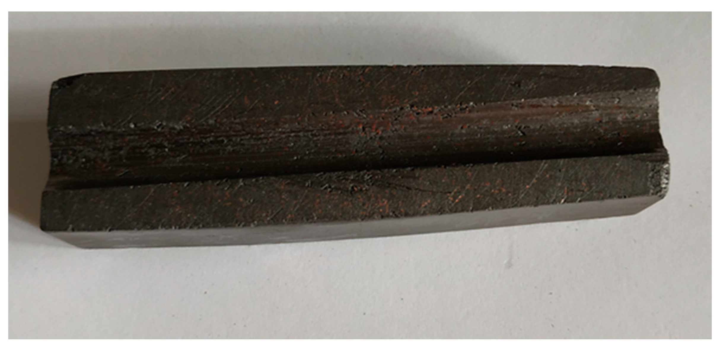
Figure 3 presents a photograph of ready-made product.
3. Measurements and Results
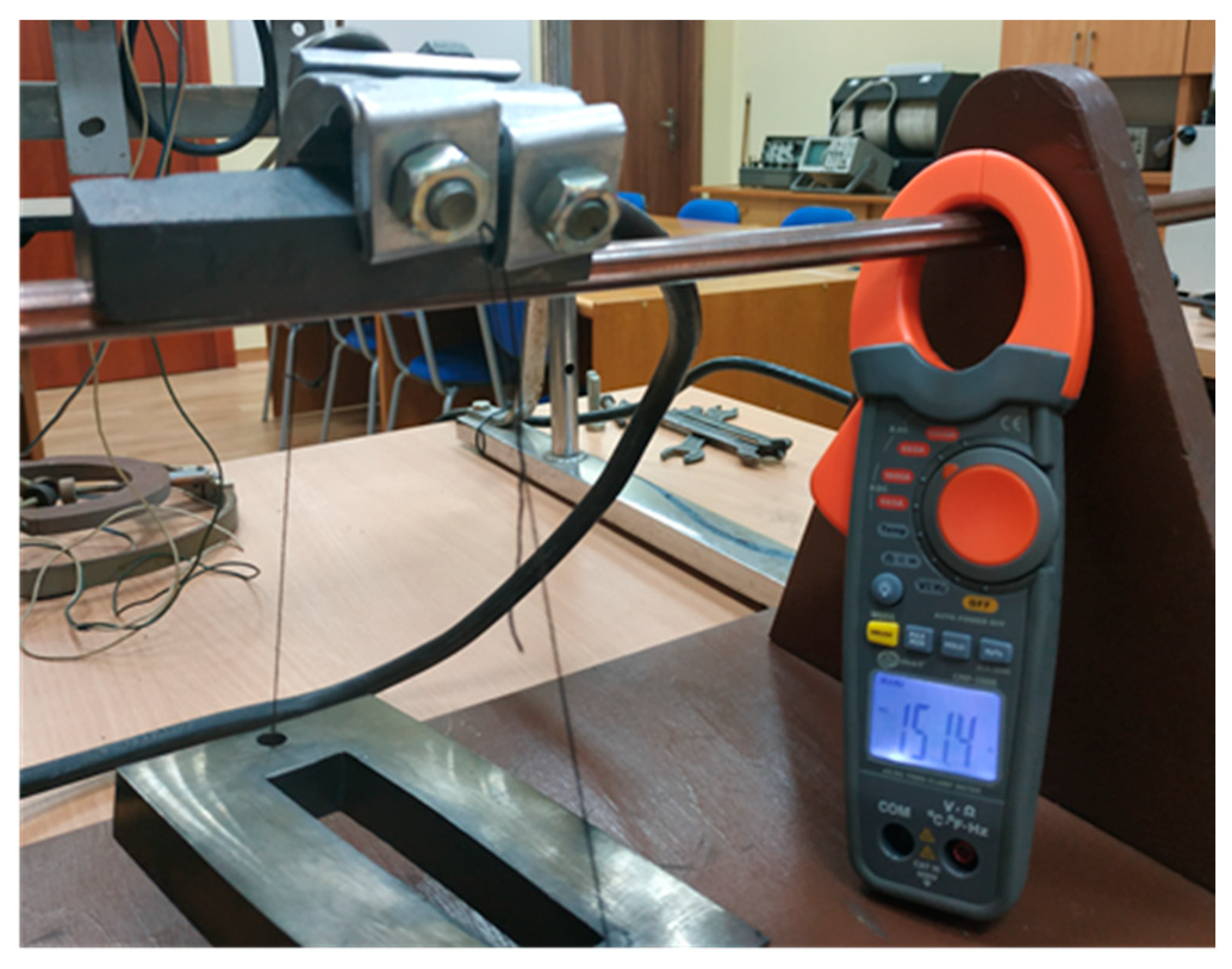
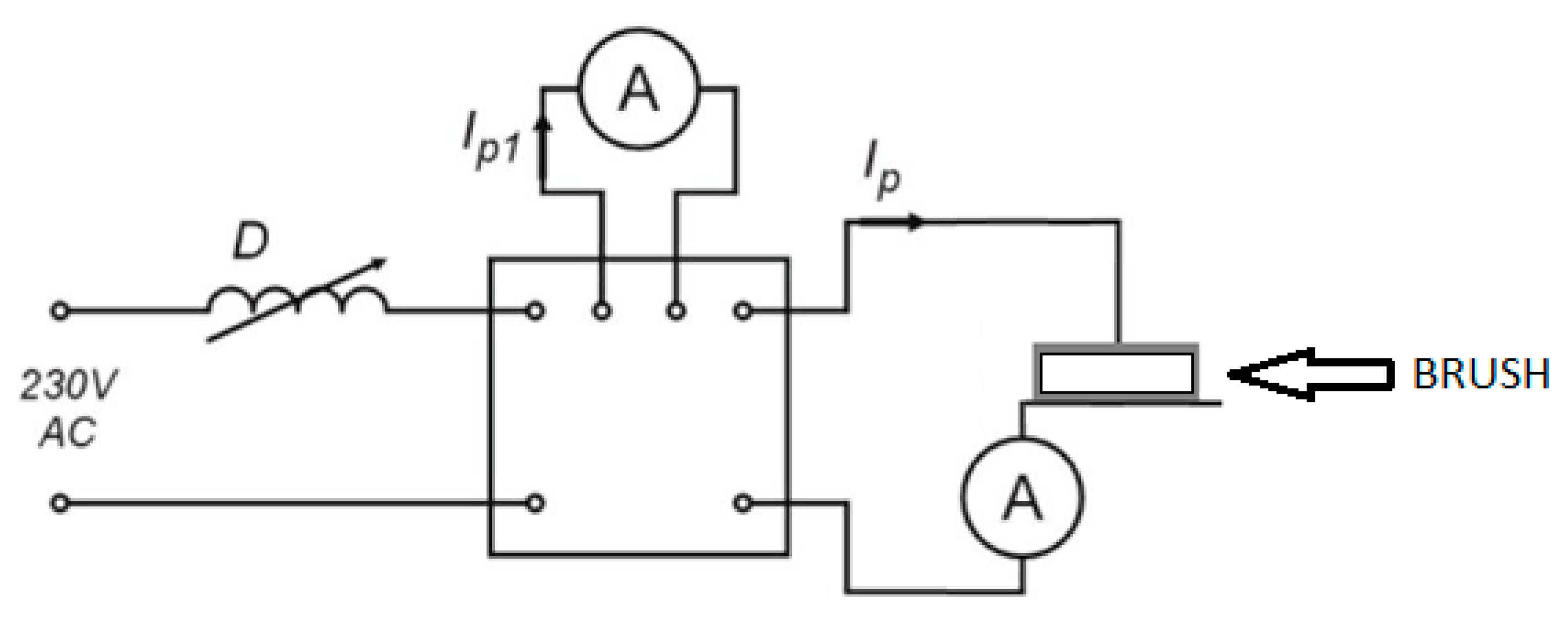
The research was carried out for various component mixtures and for commercially available brushes. Electrical, mechanical, and load properties were tested. It should be remarked that the some electrical properties (e.g., current ampacity) were examined using a laboratory stand at direct current value equal to 150 A, which might be considered as a value comparable to those obtained in real-life conditions.
Figure 4 presents a photograph of the laboratory stand for testing current ampacity, whereas in
Figure 5 the connection scheme of the setup is presented. The system brush-traction electrode is supplied from a 230 V alternating current source via a coil with adjustable inductivity (D) and an assembly box. The main current I
p in the examined system as well as auxiliary control current I
p1 are measured with ammeters.
The measurements of electrical resistance were carried out using the bridge method with the Sonel MMR-650 device (Wokulskiego, Świdnica, Poland). The four-wire (Kelvin) method [
27] suited for measurements of small resistances is implemented inside the device. A sketch of the connection scheme to the device is presented in
Figure 6. Red wires and clamps pertain to the current part of the measurement circuit. Blue wires and clamps pertain to the voltage part of the measurement circuit. The blackened ovals denote the contact points between the examined brush and the wire. “TEMP” denotes a thermopile (a temperature sensor) for monitoring ambient temperature. The measurement range for the device was 1.0000–1.9999 mΩ, resolution 0.0001 mΩ, and the fundamental measurement error ± (0.25% result of the measurement + 2 digits).
The measurement results concerning the resistance of the samples are given in
Table 1. The values provided are averaged from ten individual measurements. Description of the samples: 1—graphite + 20% resin + 20% copper, 2—original, commercially available mixture, tradename RH84, 3—graphite +15% resin + 20% copper, 4—another original, commercially available mixture, tradename MY7D, 5—graphite + 20% resin + 20% copper + 30% graphite recyclate, 6–graphite + 20% resin, 7—graphite without resin.
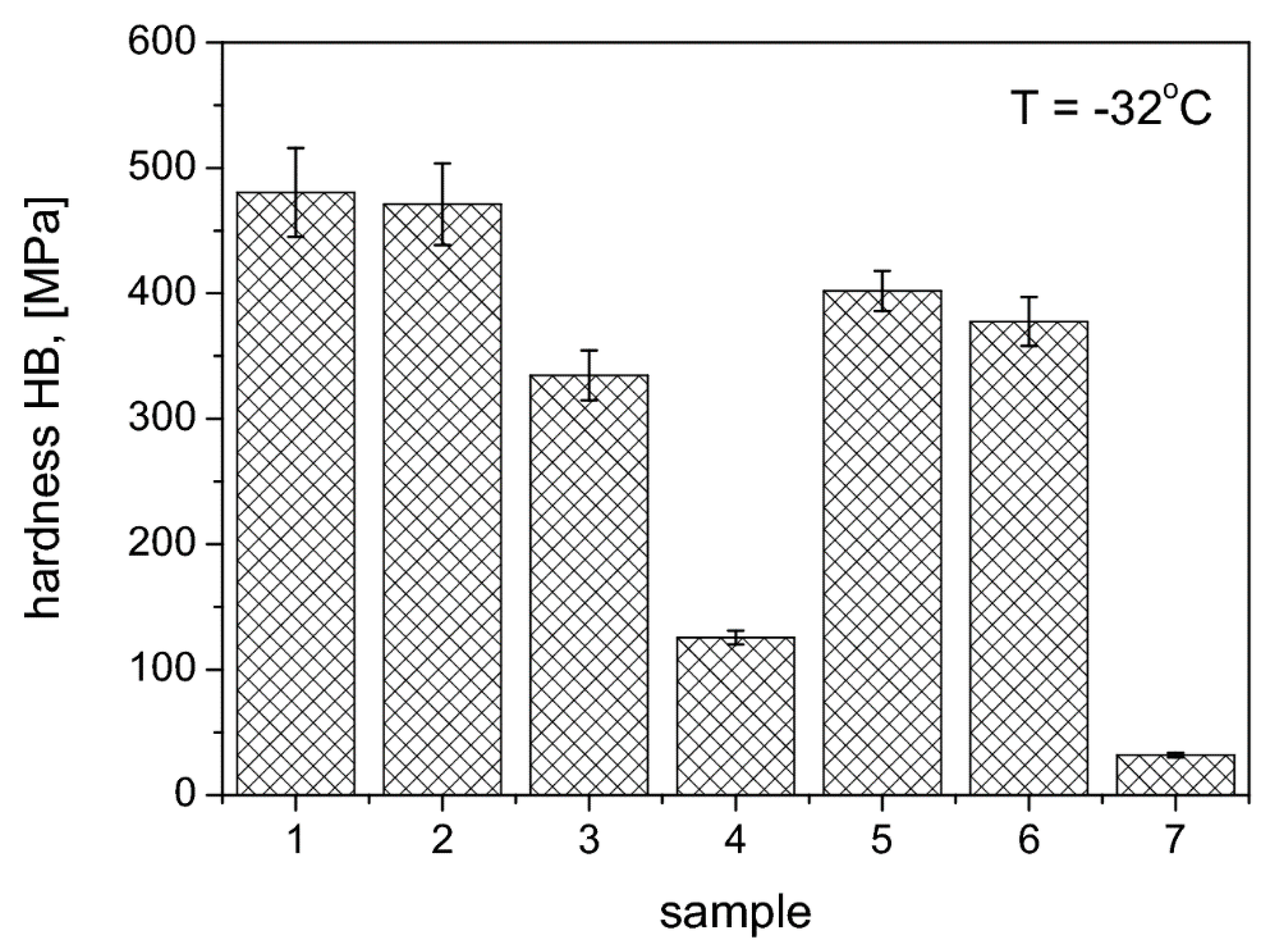
Hardness tests were carried out with the HB ball indentation method with the hardness tester HPK 8411 in accordance with PN-EN ISO 2039-1: 2004. During the tests, the ball with diameter 5 ± 0.025 mm was used. The succesive load values were 49 N, 132 N, 358 N, and 961 N. The measurements were made at a distance at least 5 mm away from the sample edge, and the distance between successive measurement point was 10 mm. The tests were carried out on samples with smooth, even, mutually parallel and perpendicular surfaces to the direction of the force, without bubbles, scratches, pits, or other visible defects. The tests were carried out at variable temperatures of 80 °C, 23 °C, and −32 °C. The results are shown as graphs in
Figure 7,
Figure 8 and
Figure 9.
Designation of the samples: 1—graphite + 20% resin +20% copper, 2—original, commercially available mixture, tradename RH84, 3—graphite + 15% resin +20% copper, 4—another original, commercially available mixture, tradename MY7D, 5—graphite + 20% resin + 20% copper + 30% graphite recyclate, 7—pure graphite without resin.
Commercial brushes made of commercial mixtures reveal considerable hardness (in particular the mixture RH84), but it varies to some extent with temperature variations. For the RH84 mixture an increase in hardness was recorded at lower temperatures, whereas for the MY7D mixture, comparable hardness values were noticed both for the room and for the negative temperatures. The lowest hardness values were recorded for the commercially available mixture MY7D” and for graphite samples. Graphite samples with the addition of graphite recyclate, resin, and copper, as well as graphite samples with the addition of resin and copper, possess higher hardness values than the original commercial mixtures.
Table 2 presents the results related to abrasion tests for some of the considered brushes. Notation: RH84 and WY7D denote commercially available compositions; S1—a mixture of carbon recyclate, “new” carbon and 15% copper and resin; S2—a mixture of carbon recyclate, “new” carbon and 15% resin; S3—a mixture of “new” carbon and 15% copper and resin. Δ10 denotes the loss in brush weight, in grams, after sliding it for 10 m distance along the traction wire, Δ100− after sliding it for 100 m distance, respectively. These values are also referred to the original brush weights and given in percentage units (denoted as Δ10% and Δ100%, respectively). From a comparison of the weight loss results, a conclusion may be drawn that the wear performance of sample S1 is superior to other presented ones.
Figure 10 depicts a SEM photograph concerning an exemplary brush developed partially from the waste materials with shredded copper braid. In the Figure we have noticed an increased graphite interlamellar spacing, due to the increase in copper level. This in turn may explain the decrease in resistance.


