Design and Application of a Smart Lighting System Based on Distributed Wireless Sensor Networks


1
School of Civil Engineering, Southeast University, 2 Sipailou, Nanjing 210096, China
2
Widelinker Intelligent Technology Co., Ltd., 29 Kejian Road, Jiangning District, Nanjing 211100, China
*
Author to whom correspondence should be addressed.
Appl. Sci. 2020, 10(23), 8545; https://0-doi-org.brum.beds.ac.uk/10.3390/app10238545
Submission received: 1 November 2020
/
Revised: 22 November 2020
/
Accepted: 27 November 2020
/
Published: 29 November 2020
(This article belongs to the Special Issue Towards a Digital Built Environment: The Role of Digital Engineering, IoT and Artificial Intelligence)
Abstract
:Buildings have been an important energy consuming sector, and inefficient controlling of lights can result in wastage of energy in buildings. The aim of the study is to reduce energy consumption by implementing a smart lighting system that integrates sensor technologies, a distributed wireless sensor network (WSN) using ZigBee protocol, and illumination control rules. A sensing module consists of occupancy sensors, including passive infrared (PIR) sensors and microwave Doppler sensors, an ambient light sensor, and lighting control rules. The dimming level of each luminaire is controlled by rules taking into consideration occupancy and daylight harvesting. The performance of the proposed system is evaluated in two scenarios, a metro station and an office room, and the average energy savings are about 45% and 36%, respectively. The effects of different factors on energy savings are analyzed, including people flow density, weather, desired illuminance, and the number of people in a room. Experimental results demonstrate the robustness of the proposed system and its ability to save energy consumption. The study can benefit the development of intelligent and sustainable buildings.
1. Introduction
Energy saving for buildings has been attracting widespread interest as the building sector is considered the most energy-consuming sector, which consumes over half of global electricity and over one-third of the overall energy [1]. The International Energy Agency predicts that the energy demand of buildings will increase by 50% by 2050 if certain measures are not conducted to improve building energy efficiency [2]. In buildings, lighting systems constitute a large proportion of energy consumption. For instance, lighting accounts for 11% of the consumed energy in residential buildings by end-use in the United States [1] and 21% of the consumed energy in commercial buildings in the United Kingdom [3]. In China, the largest growth in energy end-use in commercial buildings occurred due to the demand for lighting [1]. Hence, it is vital to develop new strategies to achieve energy saving for lighting while satisfying the illumination comfort of users.
Advances in smart technologies have brought in a new generation of building energy behaviors and control approaches, where smart lighting system has a direct impact on energy saving, user’s comfort, health, and safety [4,5]. Compared to the traditional lighting system based on manual on/off switching, the smart lighting system leverages advances in light-emitting diodes (LEDs) and information and communications technologies (ICTs), such as wireless networks and sensors, to create efficient and healthy illumination [6,7]. Using various information, such as occupant presence and available daylight, both of which can be acquired by sensors [8,9,10,11], and user preference set by building users [12,13], LEDs can be controlled automatically and efficiently by a digital input signal. Further energy saving can be realized by optimizing LEDs’ dimming levels with the objective of minimizing the power consumption of all LEDs subject to illuminance constraints [14]. However, in real applications, for instance, in commercial buildings and public facilities, the lighting is dynamic because people move randomly. As a result, optimization models have become sophisticated, time-consuming, and require high-performance hardware.
The development of a smart lighting system in real application faces three main challenges. First, due to a large number of luminaires to be controlled and the importance of lighting to people’s health and safety, a smart light system is complex and demands a short time delay. Second, a balance between system performance and the life-cycle cost is required. The life-cycle cost consists of designing, manufacturing, and maintenance costs. Generally, the more precise the system control is, the higher the life-cycle cost will be. However, the performance may not increase proportionally with the cost. For instance, the closed-loop lighting controller does not contribute to visual performance optimally [15], and the energy savings it achieves is less than that achieved by the open-loop controller in Delvaeye’s experiment [16], although the former has more accurate tuning of artificial light output than the latter. Third, compared with a wired lighting control system, a wireless system is easier to deploy and more attractive for retrofitting the existing lighting controls with minimal disruption; however, new problems can arise in wireless systems, such as higher communication traffic, larger delays [9], and underillumination [17].
Considering these challenges, this study proposed a smart lighting system that can be implemented in different types of buildings, such as office buildings, parking garages, and subway stations. The proposed system includes luminaires, sensors, a distributed wireless sensor network (WSN), and a rule base for lighting control. Each luminaire is equipped with a sensing module that controls the dimming level considering the illuminance value of daylight, occupant presence, and schedules. Illuminance value of daylight is measured by ambient light sensors inside the sensing modules equipped in the luminaires closest to windows and then broadcasted to the whole network. Occupant presence is detected by occupancy sensors, that is, passive infrared (PIR) and micro-Doppler sensors. In addition, an algorithm is designed to fuse outputs of these two types of sensors in order to improve the efficiency and accuracy of occupant detection. A distributed WSN is constructed, where one node corresponds to one sensing module. The decentralized control is adopted to decrease communication traffic and delays, and underillumination is resolved by dimming the luminaire of not only a node whose occupancy sensor interrupt is triggered but also its neighboring nodes. Using the proposed smart lighting system, energy savings can be achieved in real-application.
The contributions of this paper are as follows:
- (1)
- A smart lighting system for real-application is developed. The system is based on a distributed WSN consisting of sensing modules colocated with luminaries. Combined with the neighbor-aided dimming method, decentralized control provides sufficient illumination in a timely manner.
- (2)
- The performance of the proposed system is verified by experiments in practical environments. The proposed system is evaluated in two different scenarios, a metro station and an office room. The factors influencing energy savings are analyzed, and the results show that the energy saving in a metro station is inversely proportional to the people flow density and the energy saving in an office room was influenced by weather, desired illuminance level, location of worktables, and the number of staff in the room. Based on the results, the proposed system can facilitate the smart lighting system design.
The remainder of this paper is organized as follows. Section 2 introduces recent related work in the field. Section 3 describes the proposed system, network architectures, and the neighbor-aided illumination control method. Section 4 presents evaluation of the proposed system in two different scenarios. Section 5 provides discussion.
2. Related Works
2.1. Occupancy Sensors for Smart Lighting Control
Occupancy sensing has been widely studied, and many sensing techniques have been proposed, including PIR sensors [18,19], microwave Doppler sensors [20], ultrasound sensors [21], and Wi-Fi sensors [22]. PIR sensors have been widely used in the field of occupancy detection because they are fast and cost effective [23]. Specifically, a PIR sensor can detect radiations at a wavelength of approximately 10 microns, which is the peak wavelength of the heat energy emitted by humans [24], and its output is represented by zero or one corresponding to the unoccupied state or occupied state, respectively. Although a PIR sensor can achieve an accuracy rate of 98.4%, it often generates false-negative detection errors when occupants move slightly [23], and also fails to detect humans in hot weather. A microwave Doppler sensor utilizes the Doppler effect to analyze the frequency difference between transmitted and received signals [25]. It can not only detect the movement of objects but also monitor small movement. As microwave sensors have high sensitivity, they suffer from false alarms due to slight vibration or fast moving of objects in the air. Ultrasonic sensors are similar to microwave sensors except that high-frequency sound waves are used to detect movement according to the Doppler effect [26]. Ultrasonic sensors are highly suitable for detecting occupancy behind obstructions, so occupancy on adjacent hallways and outside of windows is also detected, which leads to false-positive errors [24]. Wi-Fi has also been proposed for occupancy sensing, especially for indoor positioning. The Wi-Fi access points detect the occupancy presence using the Wi-Fi signals transmitted by mobile devices. The disadvantage of this approach is that occupants are required to carry their mobile devices all the time [22]. Other sensors, including CO2 sensors [27] and camera [28], can also be utilized for occupancy detection. However, there is a long latency period between the presence of people and CO2 sensor responses, while the camera-based approaches require additional lighting and have high computational overload, along with privacy concerns. Merging data from different sensors can provide better results as different types of sensors compensate each other [29]. Recently, the integration of multiple sensors has been suggested to improve the performance of occupancy detection [30]. Yang et al. [31] used a radial basis function (RBF) neural network whose inputs were preprocessed sensor data including temperature, humidity, CO2, light, sound, and motion to estimate occupancy for demand-driven HVAC operations. Amayri et al. [32] estimated occupancy considering motion detection, power consumption, CO2 concentration sensors, microphone, or door/window positions, and selected decision tree technique as the prediction model. Zikos et al. [33] presented a real-time occupancy estimation method based on a Conditional Random Field (CRF) model, which combined information from sensors such as door counters, acoustic, PIR motion, and CO2 sensors, and applied the model to four real-life spaces, i.e., rest area, meeting room kitchen, and office, with different combinations of sensors. However, the performance of these fusion methods is influenced by the similarity between training samples and test samples. For example, the detection rate was 64.83% for cross-estimation compared with 87.62% for self-estimation in [31]. Wang et al. [25] designed a real-time pedestrian detection method where a PIR sensor was used at the ambient temperatures of less than 40 °C, and at the higher temperatures, it switched to a microwave sensor. The reason for such design was to avoid detection errors of PIR sensors at high temperatures while taking advantage of the low power consumption of PIR sensors. Although the temperature does not affect PIR sensors significantly in indoor environments, microwave sensors still can be used to resolve problems of PIR sensors caused by false-negative detection errors.
In smart lighting control, occupant detection is crucial to control strategy and energy savings. Several sensor technologies have been utilized to detect occupants, including PIR [34], mobile devices [22], and the combinations of PIR and microwave, PIR, and ultrasonic [35]. In most studies, sensors colocated with luminaires and detected occupant presence at individual workspace level instead of zone level and room level [36,37]. Besides, researchers proposed some methods to optimize the deployment of sensors. Wang et al. [38] formulated the optimal deployment algorithm based on adaptive binary particle swarm algorithm for sensor nodes in a plane of a building to detect targets under the full coverage and a limited cost. Norouziasl et al. [39] analyzed the feasibility of installing different occupancy sensors using a probabilistic model and a simulation software integrated with the building layout and lighting features and selected the most cost-effective one considering number of occupants, occupant presence and movement, and occupant action behavior.
2.2. Lighting Control
The architecture of a lighting system control can be centralized or distributed [34]. In a centralized control system, sensor data are transmitted to a central controller, where the dimming level for the corresponding luminaire is determined by a control law and transmitted to the luminaire [22]. In contrast, in a distributed control system, each sensing module has a controller and communicates with neighbors to calculate the dimming levels [17,19,40]. In wireless networks, compared with the centralized-control networks, a distributed control system requires larger bandwidth and has a higher cost due to larger amounts of processing and storage in a sensing module [41]. However, a centralized control system needs more time to process data in its central node, thus making the central node more complex and vulnerable and increasing the system communication traffic and delays. Considering the robustness and the latency, a distributed control system architecture is used in this study.
In order to determine dimming levels of luminaires, two different control methods are utilized: open-loop method and close-loop method. The open-loop method measures the incoming daylight and signals a controller to proportionately dim the luminaire based on the daylight contribution [42]. The closed-loop method adjusts the luminaire dimming level to ensure that the combined contribution from daylight and artificial light maintains the desired illumination level. Specifically, proportional integral (PI) and proportional integral differential (PID) are two commonly used closed-loop methods [34]. Compared with the closed-loop method, the performance of the open-loop method is affected by the absence of feedback. However, the open-loop method is more economical due to considering the limited processing capability of microcontroller in a sensing module and also, more robust to errors in the placement of light sensors. In addition, optimization algorithms and machine learning are applied to control methods to minimize total illuminance [10,14,34] and make the control system smart [42], respectively. Although the optimization algorithms can achieve high energy savings, they consume more computational resources and much time and seldom consider the movement of people.
3. Materials and Methods
3.1. System Overview
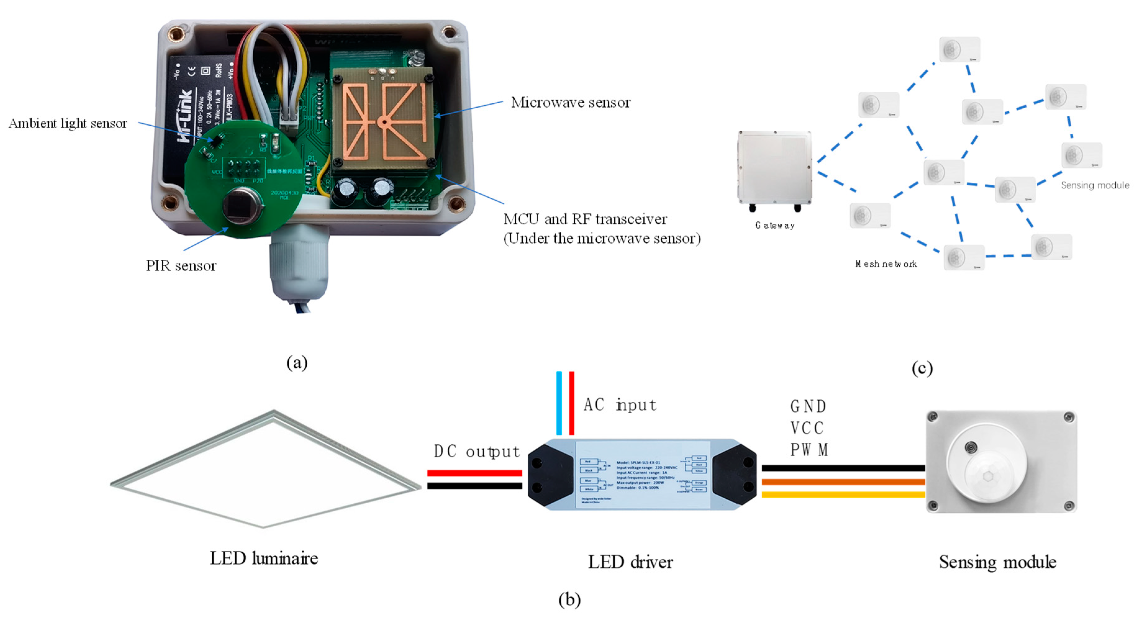
The architecture of the smart lighting system is depicted in Figure 1. As shown in Figure 1a, one LED luminaire is equipped with one sensing module and contains one or more LED sources. The specifications of LED luminaires are depicted in Section 4.1 and Section 4.2. Each module consists of two occupancy sensors, i.e., a PIR sensor and a microwave Doppler sensor, an ambient light sensor, a microcontroller (MCU), and a wireless transceiver. As shown in Figure 1b, the power of a sensing module is provided by a LED driver, and the dimming level, which is the output of the sensing module, determines the value of a pulse-width modulation (PWM) signal used for analog dimming of the LED. In the mesh topology, the sensing modules communicate wirelessly through a ZigBee-based network. In Figure 1c, a network node represents a sensing module with a belonging LED. All the nodes in the network denote routers, and each node maintains its one-hop neighbor table, where neighbors are identified using the Received Signal Strength Indicator (RSSI) value. Two gateways are deployed for every 500 nodes, which transfer data between ZigBee networks and servers. The transferred data include work states of LEDs and commands to directly dim a group of LEDs or a single one.
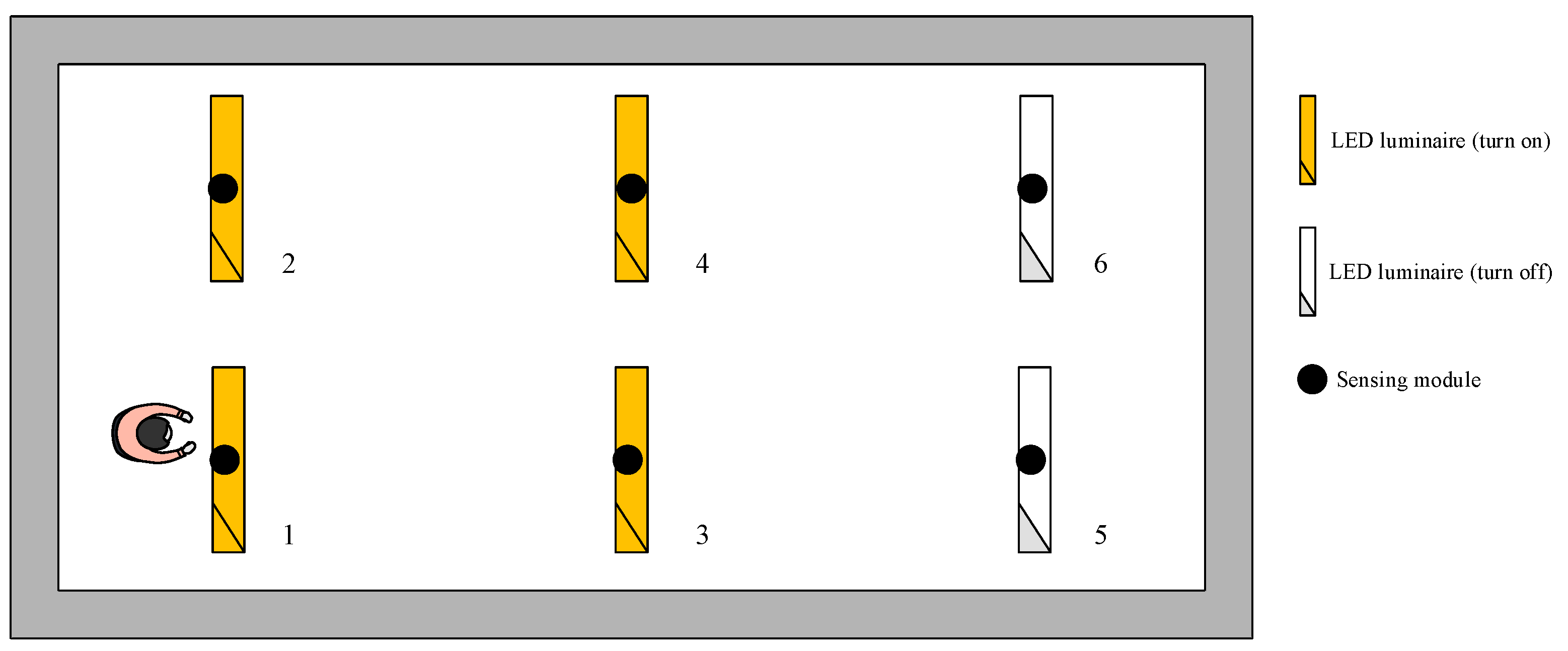
In the architecture, the LED driver is a crucial device, and a constant current driver with PWM dimming control is selected as the LED driver. First, it converts the incoming 50 HZ alternating current (AC) line power at voltage of 220 V to the regulated direct current (DC) output current to the LED. Second, the driver provides an auxiliary output voltage to power the sensing module through VCC and GND pins, shown in Figure 1b. Third, the dimming level determined by lighting control strategy in the MCU of the sensing module is converted to an analog signal level, which is input to the driver to control the level of the LED brightness. Figure 2 shows a simple example of the interaction between a LED luminaire and its colocated sensing module. When sensing module 1 detects occupancy, as a result of its control strategy the dimming level of LED luminaire 1 is set to 100%. At the same time, as its neighbor luminaire 2 and 3 are informed to dim up to 100%. The control strategy is detailed in Section 3.2 and Section 3.3.
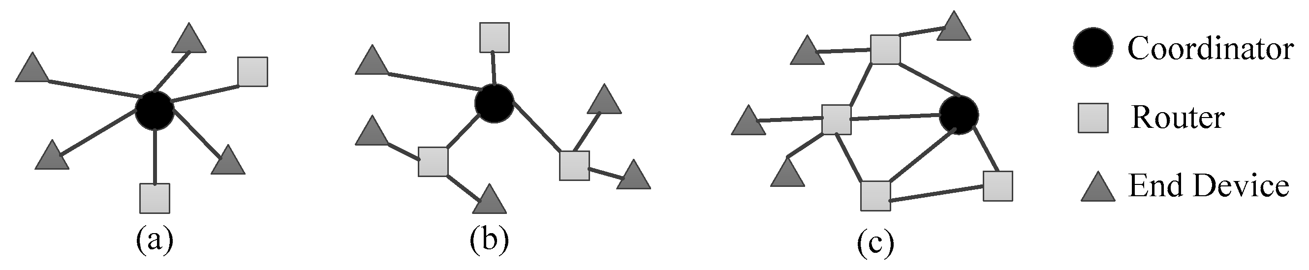
One of the aims of this work is to design a control system that can reduce the energy consumption of the lighting system using a scalable, low-power, and standardized sensor network for commercial applications. Due to the advantages of being low cost and low power, ZigBee is suitable for a sensor network. The ZigBee protocol stack consists of four main layers: physical layer, medium access control layer, network layer, and application layer. The network layer of ZigBee can have star, tree, or mesh topology, as shown in Figure 3. Specifically, each node in the proposed lighting system has a routing capability, so end devices are not necessary to be used in the network. The mesh topology is more suited for wireless lighting control than the other two topologies because neighbors in one-hop of the node that detects occupants can be easily found through searching the neighbor table and ignited to resolve the underillumination problem. On the contrary, a node in a star or tree network stores only the address of its parent node. The mesh ZigBee network is realized using the CC2530 system-on-chip of Texas Instruments. The CC2530 has functions of radio frequency transmitting and receiving and the ZigBee stack.
3.2. Occupancy Sensing and Daylight Sensing
PIR sensors and microwave Doppler sensors are commonly used for occupancy sensing. A PIR sensor is an electronic sensor that detects infrared light radiated from targets in its field of view (FOV). In the proposed system, the RE46BN-P PIR sensor is used, and its specifications are listed in Table 1. When a person enters the sensing range of the sensor, the output voltage is 5.5 V, and when people leave the sensing range, the output voltage automatically decrease the high level. The sensing circuits are enclosed in a metallic can to protect them from environmental interference, such as noise, humidity, and external electromagnetic fields. A microwave Doppler sensor utilizes the Doppler effect to detect moving targets. The MS-220 is used, and its specifications are also listed in Table 1. When motion is detected, the sensor’s TTL-level output pin switches from low (0 V) to high (3.3 V) for a finite time (2–3 s) before returning to its idle (low) state.
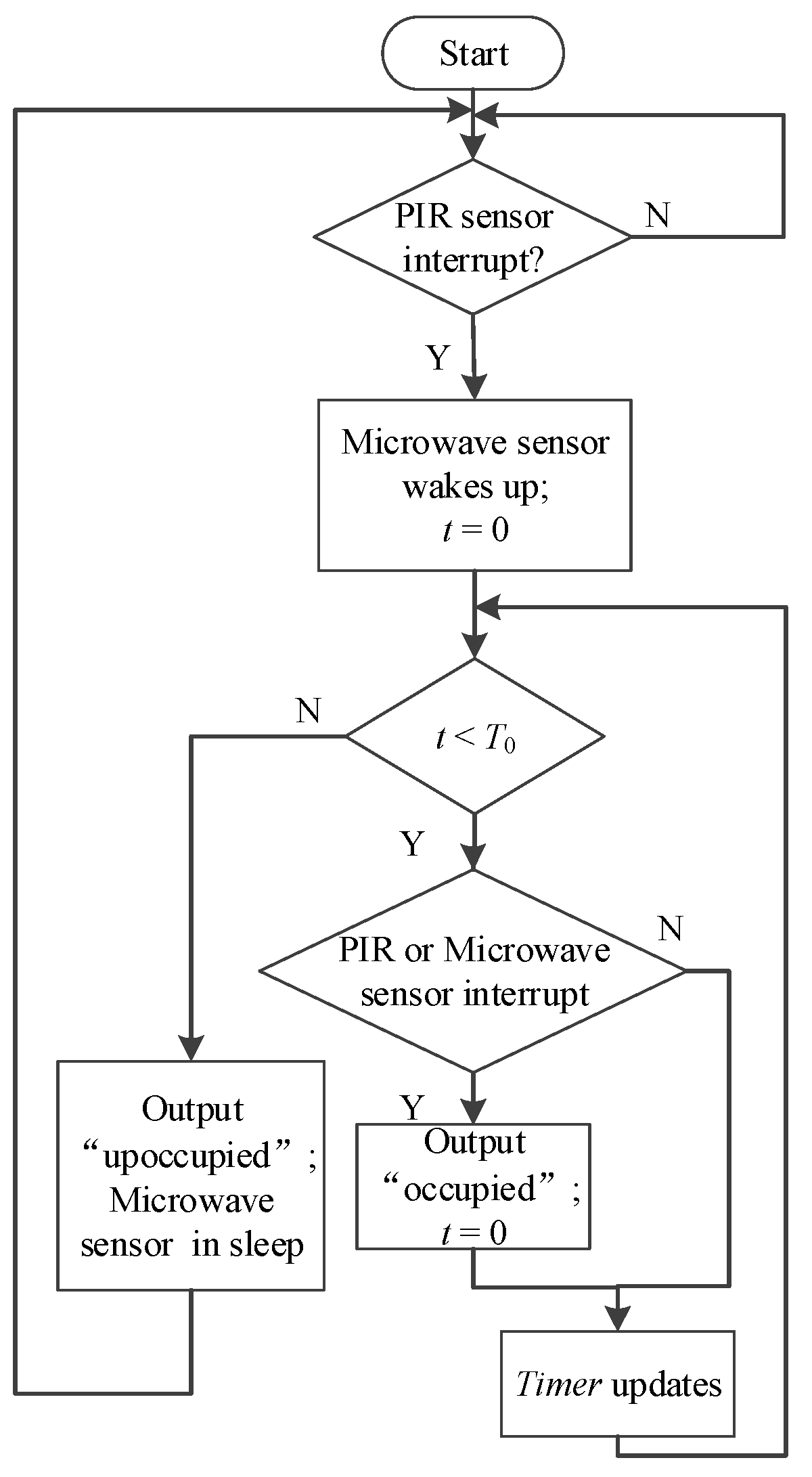
To improve the performance of occupancy detection, a data fusion method is developed using the data collected by the PIR and microwave sensors. The main flowchart of the data fusion method is presented in Figure 4, where it can be seen that at the beginning, the microwave sensor is switched off, and the PIR sensor passively detects infrared radiations. When a person enters the sensing area, the PIR sensor produces a high-level output, and the microwave sensor is activated. At the same time, a timer is set to zero and starts counting. Once the sensor detects a person in the sensing area, the timer will be reset to zero and restart counting. If the value of the timer is greater than a threshold value T0, it is considered that the area is unoccupied and the microwave sensor can be put in the sleep mode. After the microwave sensor wakes up, the occupancy sensing result is determined based on the microwave sensor output. There are two reasons why the PIR sensor output is used to control the microwave sensor. First, PIR sensors have fairly low power consumption, and when people walk into their sensing area, their accuracy rate is high. However, PIR sensors are prone to error detection of small movements when people stay in the sensing area. Second, microwave sensors are highly sensitive, so they are prone to be triggered falsely when used alone, but they are well suited for little movement detection.
Interior artificial lighting can be reduced when there is daylight, thus reducing energy consumption. Therefore, light sensors are utilized to capture the illuminance value of daylight in the external environment, and measured values are sent to the sensing modules through the wireless sensor network. Ambient light sensors are sensors of light, which convert light photons into the current. One type of light sensor is a photodiode that is sensitive to sunlight radiation. The BH1750FVI light sensor based on the photodiode is used in the proposed system. The BH1750FVI is a low-cost digital ambient light sensor with low power consumption, wide detection range, and high detection resolution. The output voltage is converted to digital 16-bit data representing the illuminance of light. Light sensors are placed in the sensing modules equipped with the LEDs that are closest to windows. The illuminance value of daylight at time t detected by a light sensor m attached to LED n can be expressed as:
where denotes the output of a light sensor m at time t, and denotes the illuminance value of LED n with a dimming level L. The illumination contribution of luminaires to a light sensor is simplified as , which indicates that only the contribution of LED n colocated with the light sensor m is considered. The reason is that during the day, the amount of natural light coming in from a window will be relatively larger than the amount of light emanating from the LEDs. Besides, since most sensing modules are ceiling mounted, the coupling between LEDs can be neglected. is obtained in the absence of daylight and stored by the sensing module. At night, the sensing module containing light sensor m dims LED n at level L, with other luminaires off, and collects the measured illuminance value at light sensor m. As illumination contributions due to the luminaires and daylight are additive [15], Equation (1) can be obtained.
3.3. Lighting Control Based on Rules
This section describes the open-loop lighting control system. This control system is energy efficient and simple to design. An important component of this system is the rule base consisting of if-then rules. The output of the rules is the dimming level of a LED luminaire n at time t, denoted as , and the input consists of the occupancy state detected by the sensing module connected to LED n, schedule , location , distance between LED n and windows , and daylight illuminance value . The control rule can be expressed by:
In Equation (2), the schedule is preferred by the user, which defines activities in different times. The location represents the type of space, such as a meeting room, a manager room, and an office room. If the luminaire located in a zone where daylight harvesting is implemented, the distance between n and windows decides the types of subzones for daylight harvesting and the value of the distance is replaced with the subzone type. All three values are set by the user through a supplied software. and are determined by the occupancy sensors, the sensing module colocated with luminaire n, and the light sensor nearest to windows. An example of the function is introduced in Section 3.3.1.
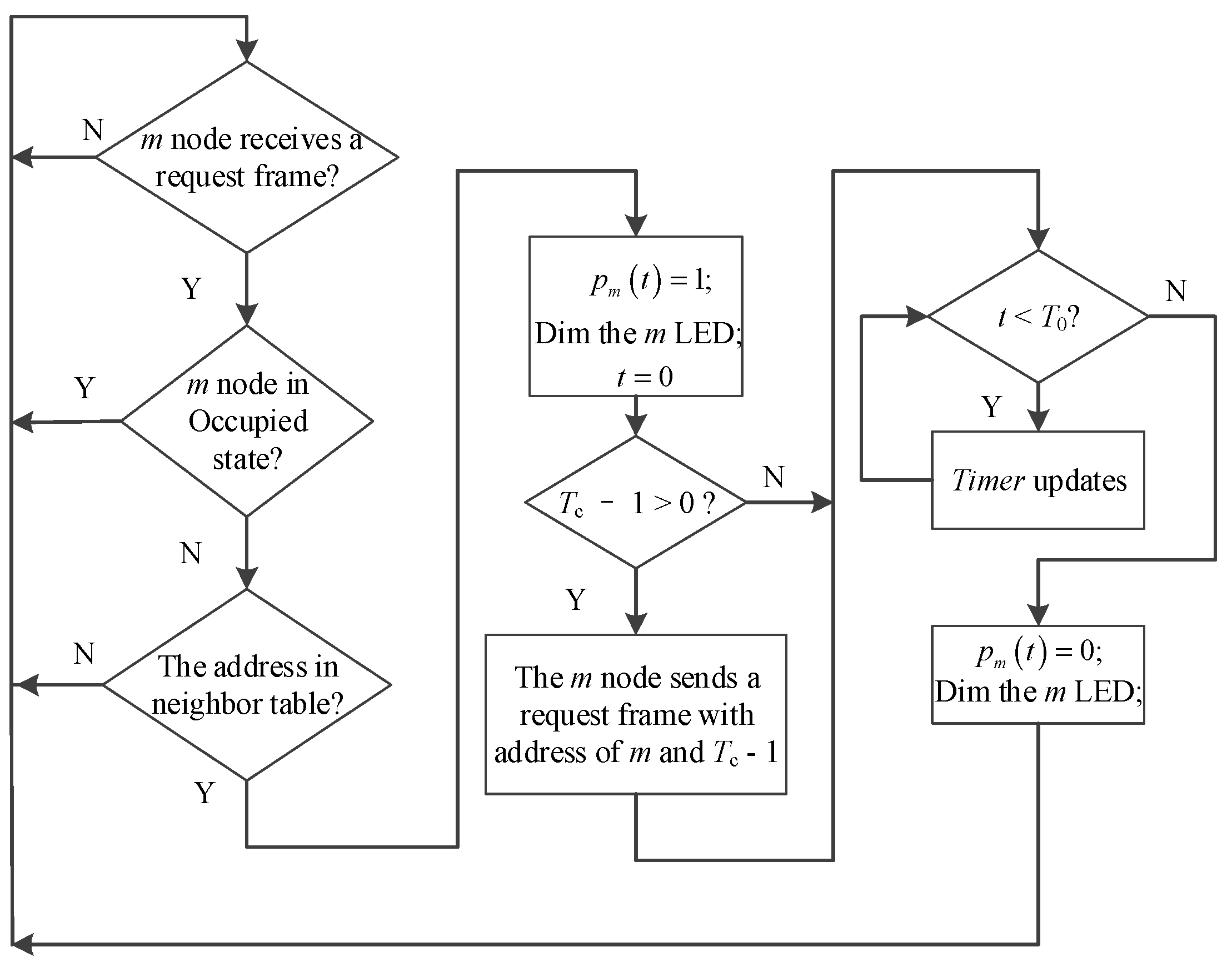
Since the illumination at the associated zone of LED n is influenced by the light outputs of LEDs in its neighborhood, the controller of LED n seeks aid from neighboring LEDs by transmitting a request frame. The request frame contains two types of data: address of transmitter and forwarding count . Consider the controller of wireless sensing module m shown in Figure 5. After reception of the request frame from LED n, the controller compares address with the stored record at its one-hop neighbor table to determine the occupancy state of m. If there is a match, which indicates m is a one-hop neighbor of n, is set to one, and the dimming level is calculated using Equation (2); namely, indicates that the associated area of m is occupied, while indicates that the associated area of m is unoccupied. Further, the controller of m determines whether to forward a request frame to its one-hop neighbors continuously. The timer value of indicates that one-hop neighbors of m are needed to provide aid to n. In this case, module m transmits a new request frame with address and forwarding count . Once Timer of m is , , and reset to the unoccupied-state values. The controller of n keeps on broadcasting request frames to alert other nodes if its occupancy state is occupied.
3.3.1. Lighting Control Rules for Office Environment
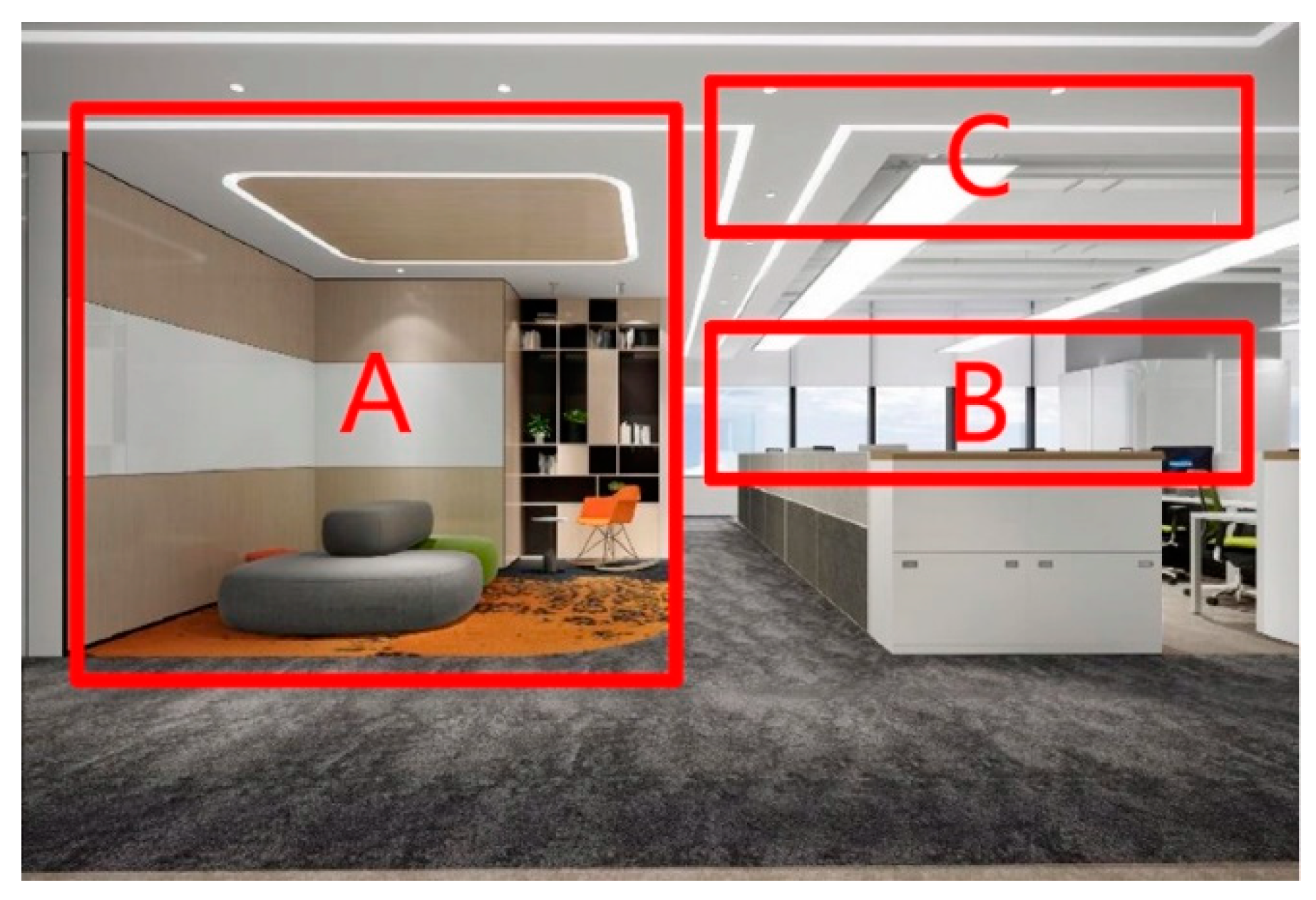
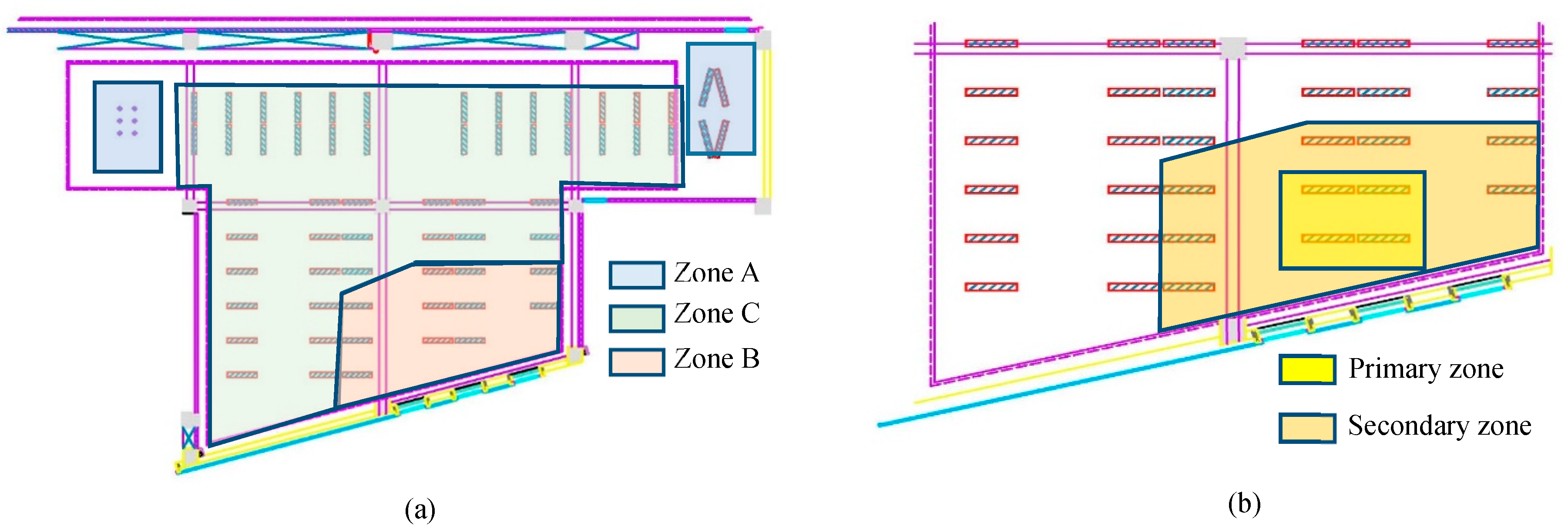
An indoor environment can be divided into multiple zones, each of which requires different lighting conditions. For instance, in Figure 6, an office space with three zone types are presented, Zones A, B, and C. Zone A is for leisure time, while zones B and C are for working. Zone B is near the windows, having great potential for harvesting daylight. On the contrary, zones A and C lack natural light, and daylight harvesting cannot be conducted in these zones. Moreover, body motion in Zone A is usually large, making it easy to sense occupancy. However, in Zones B and C, small movements often occur. The layout of the sensors is given in Table 2. The lighting control rules are obtained based on Equation (2) and considering environmental conditions and user preferences are listed in Table 3. When occupants are detected, and the associated LED is dimmed according to the rules, the neighbor LEDs will also be triggered, as presented in Figure 5.
For Zones A and C, since the daylight harvesting cannot be implemented, when occupancy is detected, the dimming levels of the associated LED and its neighbors are set to 100%. When the occupancy state is unoccupied, and its neighbors’ states are unoccupied, the dimming level is related to the stage type in Table 3. On stage 1, 2, or 6, the dimming level of the unoccupied state is set to 0%; this is nonworking time, and aggressive energy management can be utilized. On stage 3 or 5, the dimming level is set to 10% with no occupancy in order to decrease the impact of illuminance change when people enter the sensing area and improve the comfort level. Stage 4 is the lunch-break time, during which staff can take a nap in the office with dimming level of 10%.
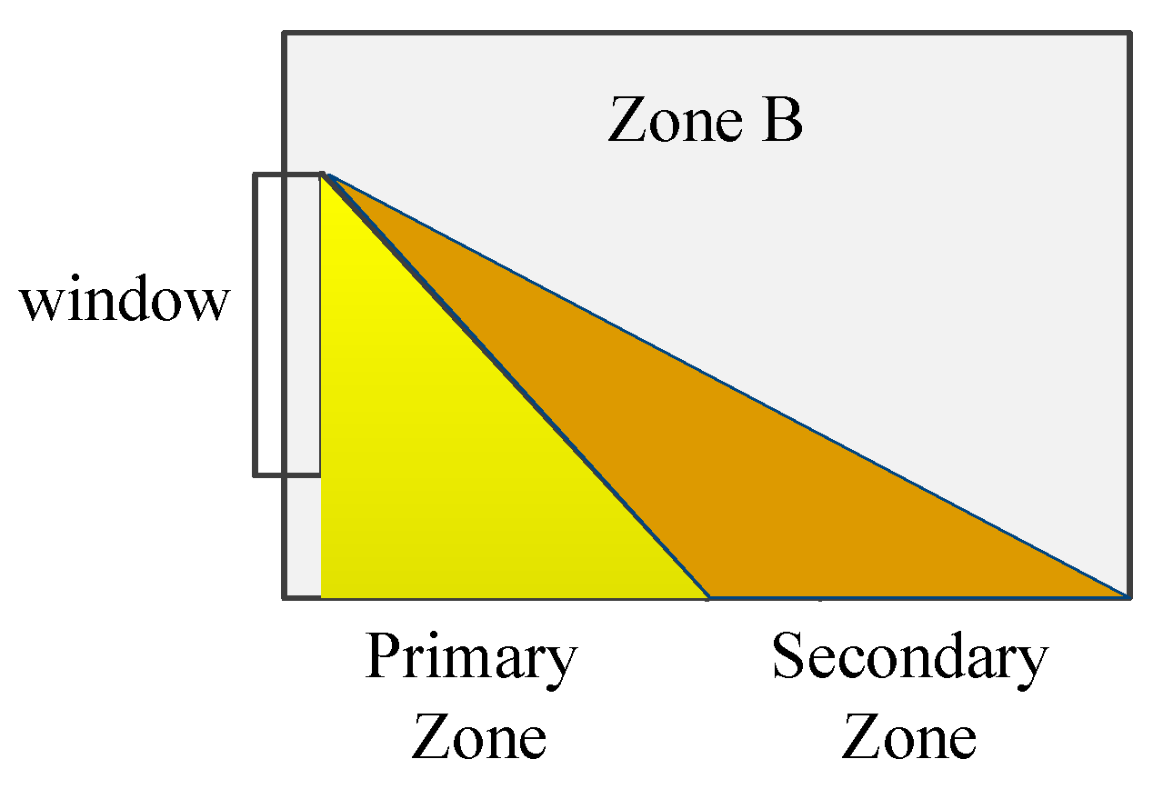
For Zone B, the control rules are the same as for Zones A and C on stages 1 and 6 when the daylight illuminance is weak and in stage 4 when the dimming level of lights are set to 10% for lunch break. In stages 2, 3, and 5, daylight harvesting is implemented in Zone B. According to the distance to the window, Zone B is subdivided into two parts: primary zone (PZ) and secondary zone (SZ), shown in Figure 7. The PZ represents the area adjacent to the window, the SZ represents the area adjacent to the PZ. The dimming level of a LED in PZ or SZ is denoted as , where . When an occupant is detected, increases by 40% with z taking the values corresponding to PZ and SZ, and the maximum value of is 100%; the value of depends on the illuminance value of daylight, and it can be expressed as follows:
where represents the illuminance value of daylight detected by the light sensors in the area closest to the window. is broadcast to all the sensing modules in Zone B through the wireless sensing network. When the occupancy state is determined as unoccupied, of Zone B is set to 10% if it does not receive request frames from its neighbors. The most important objective of the rules is to ensure that the illuminance value on the working plane meets the specification requirements, such as 500 lx for desks in high-end offices. The values in all rules are calculated based on the specification requirements, and simulation results of illuminance distribution on desks using lighting software DIALux (https://www.dialux.com/zh-CN/) and on-site measurement results. On-site measurement contains two steps. The first step is to measure and illuminance distribution at different times during the day turning off all luminaires. The second step is to measure illuminance values on a desk when the associated luminaire of the desk is dimmed at different levels and other luminaires are off and illuminance values on the same place when dimming one of its neighbors at different levels and keeping other luminaires off. After all of its neighbors are dimmed in turn, the measurement is transferred to another desk. The PZ and SZ are first determined, and then, values of parameters in Equation (3) are calculated. Moreover, rules in Equation (3) are designed for an office room in Section 4.2, and rules need to be redesigned for different rooms and different buildings.
3.3.2. Lighting Control Rules for subway environment
Generally, the distribution of passenger flow in a metro station can fluctuate significantly. When the number of passengers in a station is small, dimming all LEDs to a 100% level is inefficient and also unnecessary, but dimming down some of the LEDs is unsafe and can be uncomfortable for passengers. Therefore, the solution is to track the routes of passengers and control the lighting accordingly while considering both energy saving and user comfort.
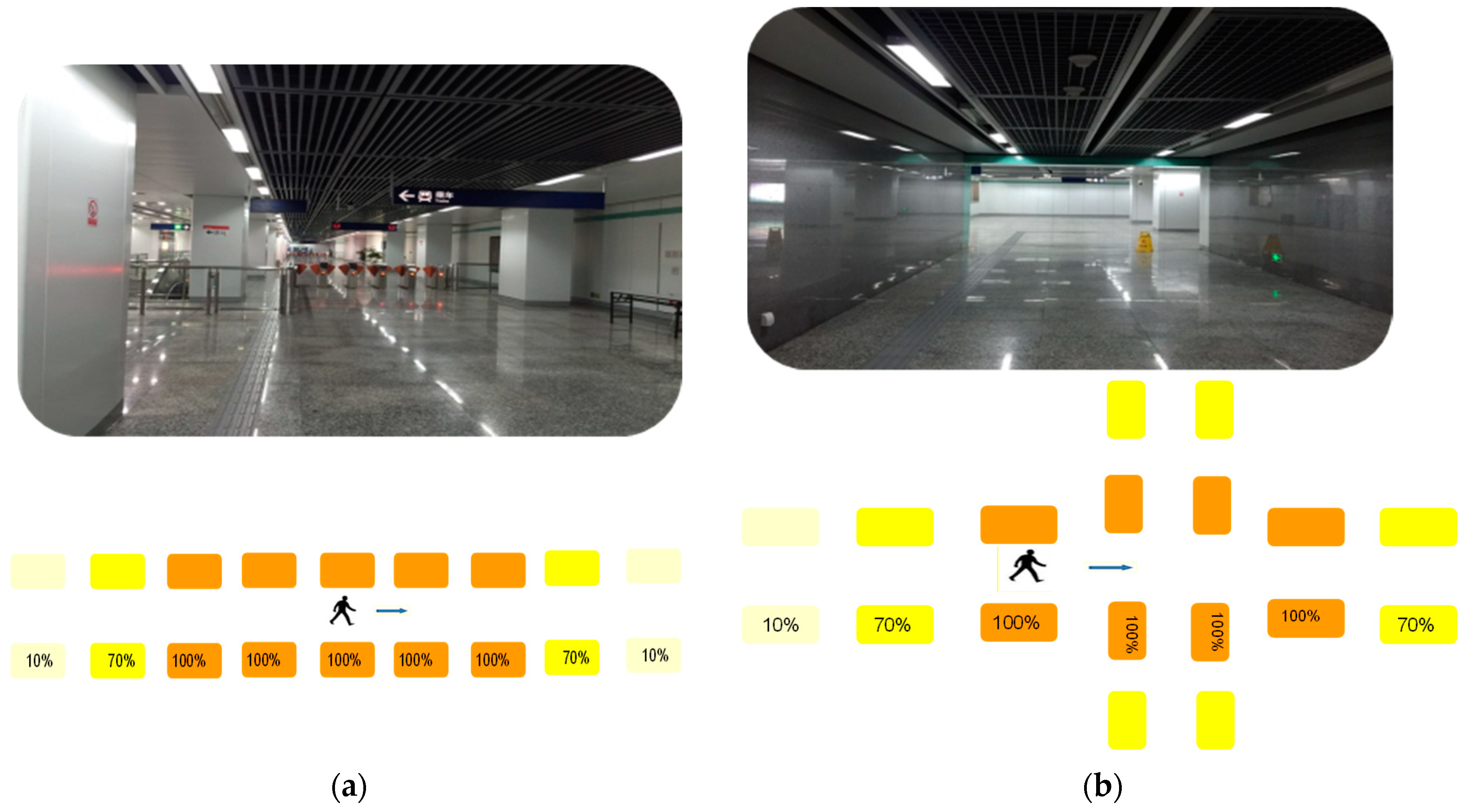
The open-loop control method can be used in the subway environment in the same as in the office environment. However, daylight harvesting cannot be implemented, and the dimming level of a LED in the subway environment depends on a user’s route. The two most common walking scenarios in a subway station, i.e., walking straight forward and passing an intersection, which are shown in Figure 8a,b, respectively. The design principle is that the illuminance change cannot be detected by a passenger or is hardly noticeable. Therefore, the illuminated area on a route should be long enough to cover most of the FOV of a passenger. In Figure 8a, the dimming level of the LED right above the passenger is 100%, as well as the dimming levels of the two LEDs ahead and behind of the passenger. The third LEDs in both directions are dimmed to 70%. The remaining LEDs are dimmed down to the default level of 10%. The advantage of this control strategy is that with the help of the symmetry of the illuminated area, the strategy can be realized based on the occupancy detection result without knowing the passenger movement direction, which could cost extra equipment and programs to be determined. The forwarding count in the request frame starts from three, and its value is reduced by one every time it is transmitted to a neighbor. When a sensing module receives from its neighbor a request frame whose forwarding count is equal to one, the dimming level of the associated LED is set to 70%. In Figure 8b, LEDs nearest to the crossroad are allocated to one group. If any LED in the group is triggered by a passenger, LEDs at the other three directions are automatically dimmed to 100%. The second LEDs in four directions are dimmed to 70% according to the received request frame. Turning on LEDs in all directions is conducted because it is difficult to predict the wanted direction of a user.
4. Results
In this section, the energy-saving performance of the proposed smart lighting system in real-life conditions is evaluated. Two testing scenarios were used, metro station and office room. The first test was conducted in the metro station to check the functionality of the proposed system, and the second test was conducted to evaluate the reaction of the proposed system to environmental conditions and schedules.
4.1. Scenario 1: Metro Station
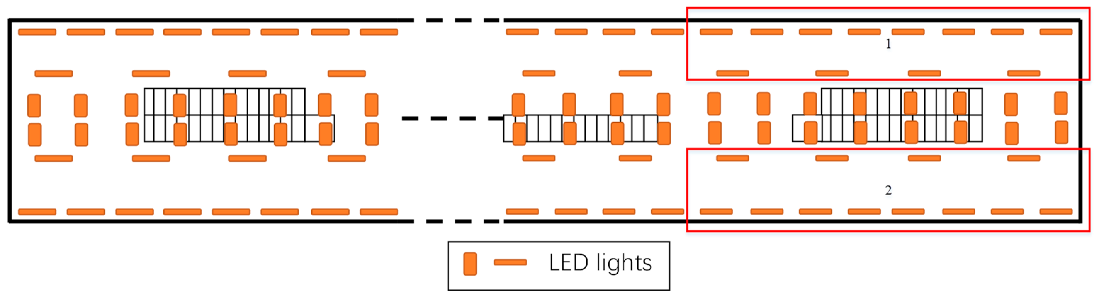
The proposed smart lighting system was implemented in an underground metro station in Nanjing, China. This station consists of a concourse level and a platform level. The simplified floor plan of the concourse level with 276 luminaires is presented in Figure 9. Each luminaire in the level was equipped with a wireless sensing module except in zone 2, which was used as a comparison zone in the energy-saving tests. Zones 1 and 2 were symmetrical and had the same geometry size and number of luminaires. The difference between zones 1 and 2 was that zone 1 utilized the smart lighting system, while zone 2 used the normal lighting system. Under these conditions, the experiments were conducted for 1 month without any interruption, demonstrating high robustness and reliability of the proposed system, including sensing modules and ZigBee networks.
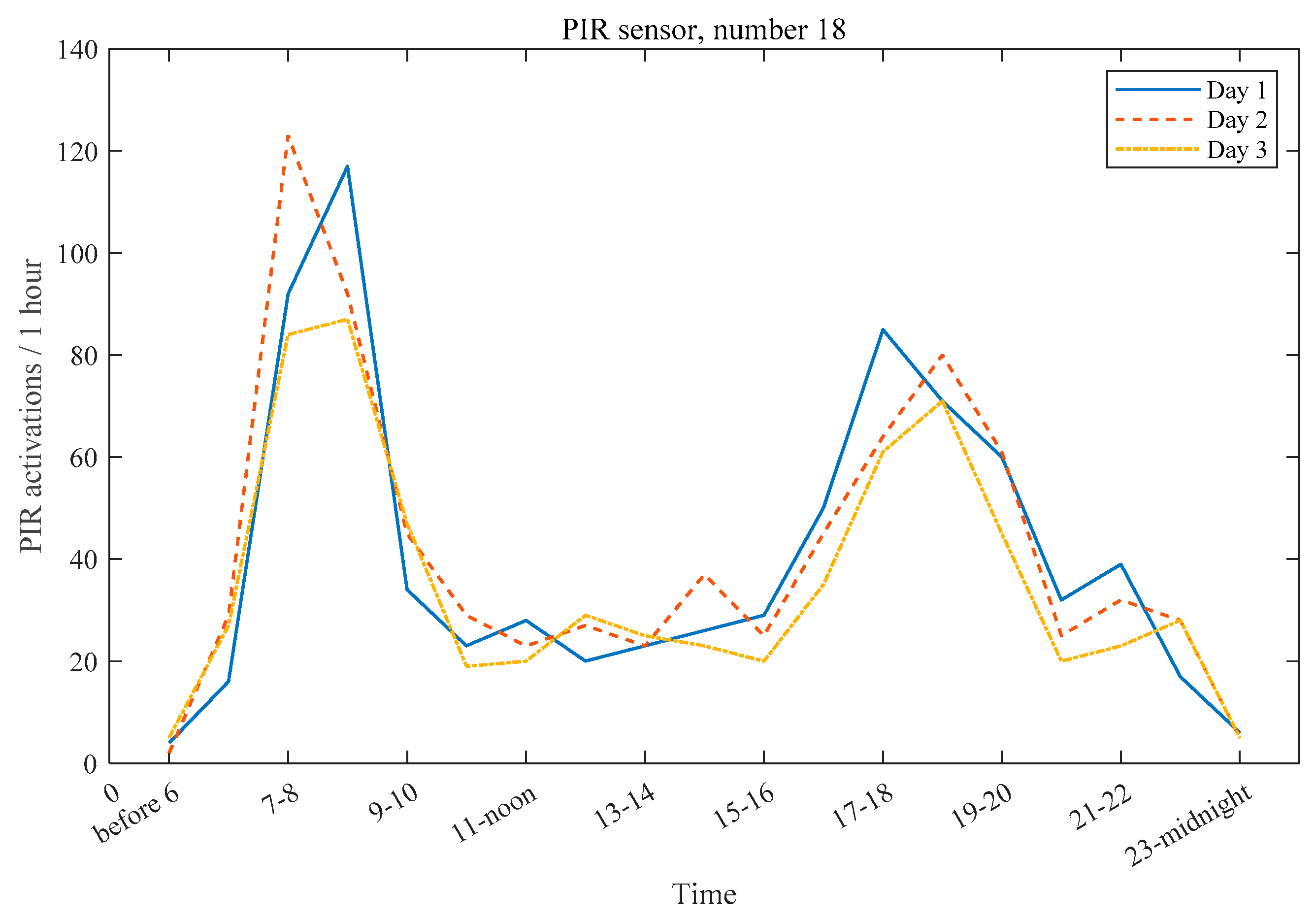
The occupancy and dimming-level data were analyzed to evaluate the occupancy detection performance of the proposed system and to investigate the impact of passenger flow on energy saving when the proposed smart lighting control is used. The PIR activations recorded by one sensor node (number 18) in zone 1 during 3 days are shown in Figure 10, where high occupancy can be observed between 7 a.m. and 9 a.m. and between 5 p.m. and 8 p.m., which was caused by commuting needs. The metro station was closed from midnight to 6 a.m., and in that period, inspection and maintenance work were carried out by the staff, which can explain occupancy detections before 6 a.m. in Figure 10. As passengers were mainly commuters and there were not many other passengers who used the station for leisure or tourism, the PIR activations were low in the other time periods. The distributions of PIR activations met the characteristics of people flow in the station.
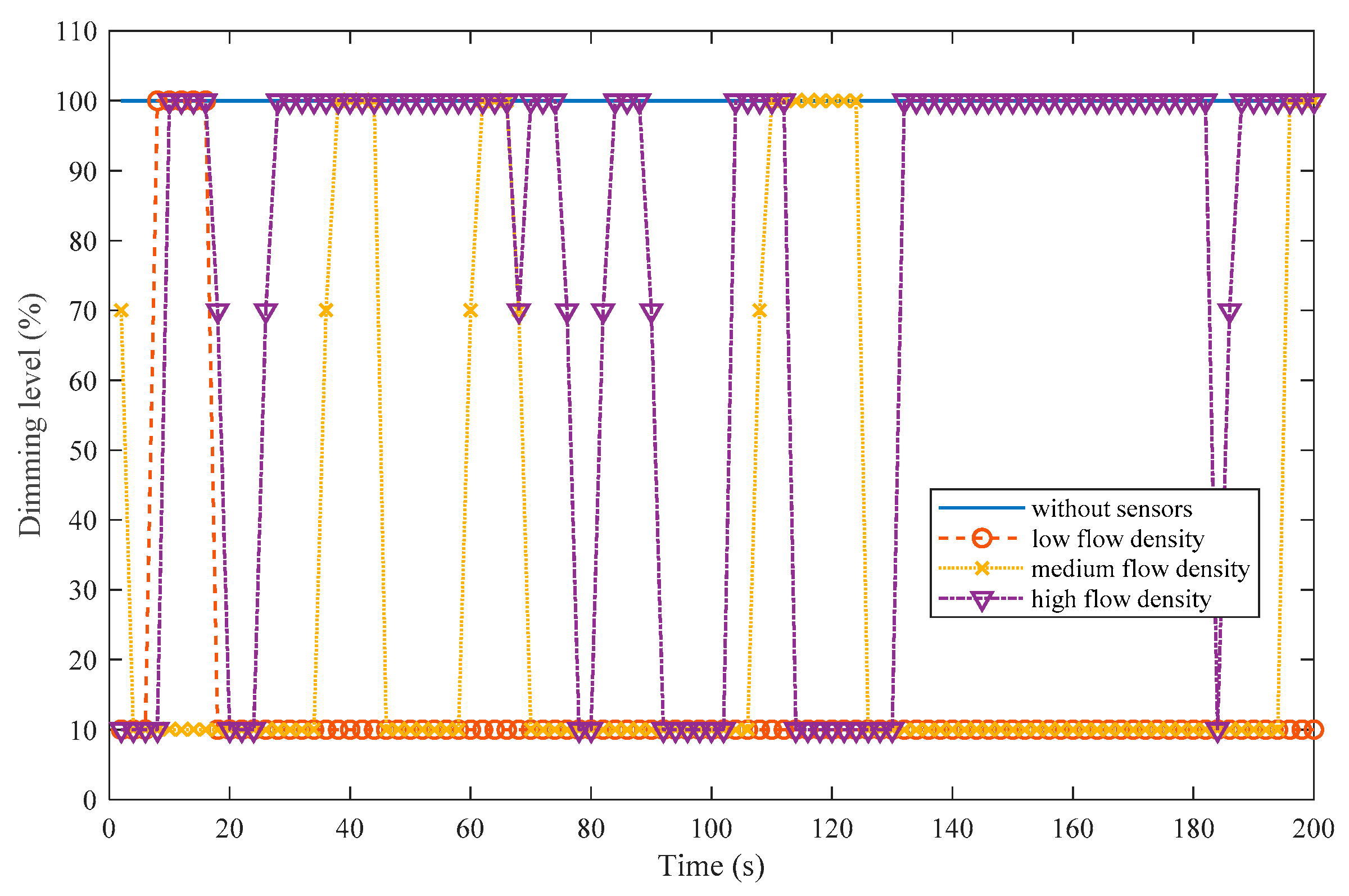
The comparison of dimming levels of a luminaire in zone 1 under different people flow densities with respect to a luminaire in zone 2 is presented in Figure 11. The lighting control strategy depicted in Section 3.3.2. was used in zone 1, and zone 2 utilized a normal lighting system without occupancy sensors in which luminaires were at a 100% dimming level during the metro operating time and most of them during the metro nonoperating time. Three types of people flow densities were considered: low density, medium density, and high density. As shown in Figure 11, with the decrease in the people flow density, the proportion of time when the dimming level was 10% increases. A higher dimming level indicated greater energy consumption. Thus, the higher the proportion of 10% level was, the more the energy savings were. Hence, the energy savings were inversely proportional to the people flow density. Accordingly, two conclusions can be drawn as follows: (1) based on the occupancy detection data presented in Figure 10, the largest energy saving occurred between 11 p.m. and 7 a.m., followed by time period from 11 a.m. to 3 p.m. and (2) the smart lighting system should be preferentially installed in metro stations with small passenger flows in order to save more energy.
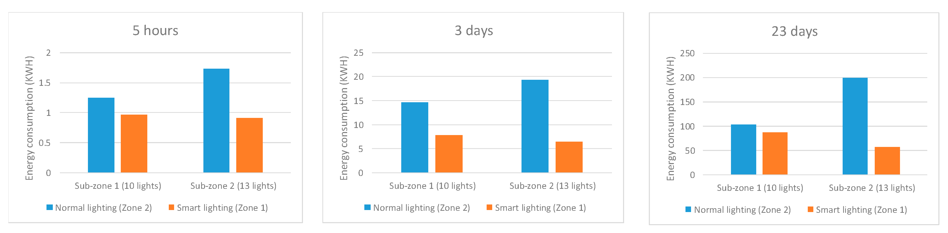
In order to evaluate the proposed system in terms of power saving, the comparison experiments were conducted in two zones, which had the same geometry size and number of luminaires except for the deployment of the smart lighting control system. Each zone was further divided into two subzones, of which one had 10 LED luminaires, and the other had 13 LED luminaries. One luminaire has two LED tubes, and the specifications of luminaires are listed in Table 4. After the installation of the proposed system in zone 1, the energy consumptions of the four subzones were measured in 5 h during the periods of 3 days and 23 days, successively. The energy consumption and saving of the four subzones are presented in Figure 12 and Table 5. In the normal lighting system, subzone 2 consumed more energy than subzone 1, which was expected because subzone 2 had three more lights than subzone 1. However, in the smart lighting system, the energy consumption of subzone 2 was slightly lower than that of subzone 1, which indicated that the energy consumption under the proposed smart lighting system was independent of the number of lights. The average energy saving achieved using the proposed smart lighting system was about 45% compared to the normal lighting system.
4.2. Scenario 2: Company Office
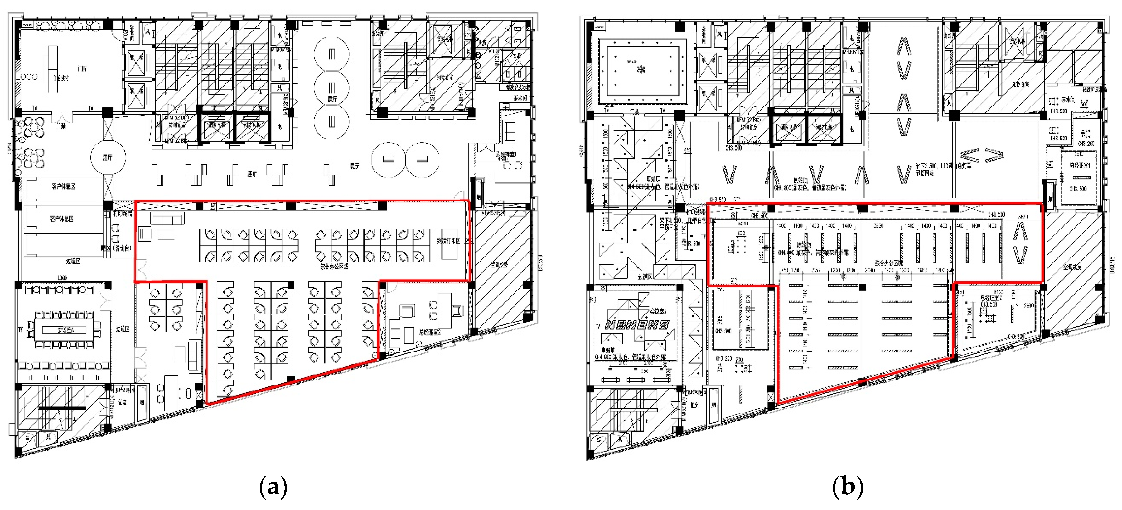
The second test scenario of the proposed smart lighting system was a 1399-m2 multifunctional office located on the 4th floor of a building at Ningbo city, China. The floor plan of the office and the layout of luminaires are presented in Figure 13. The requirement for illuminance on the work plane was 500 lx. All luminaires were LEDs, and their types, power, and numbers were listed in Table 6. Each luminaire was equipped with a wireless sensing module. The maximum sensing distance was set to 2 m. As shown in Figure 13, the largest office room highlighted with red lines was selected for the experiments, and the control strategy for smart lighting depicted in Section 3.3.1 was used. Zones A, B, and C in the control strategy are depicted in Figure 14a. In this case, Zone A included a leisure space in the upper left corner and an area for printing in the upper right corner. Office cubicles were placed in Zones B and C. Moreover, 62 line lights and 6 downlights were used in Zone A, B, and C. The locations of the PZ and SZ of Zone B for daylight harvesting are shown in Figure 14b. The ambient light sensor was deployed in the LED that was the nearest to the windows. The illuminance value of the light sensor was about half of the illuminance of daylight on the desktop right below the light where the sensor was located. The control rules were defined by Equation (3).
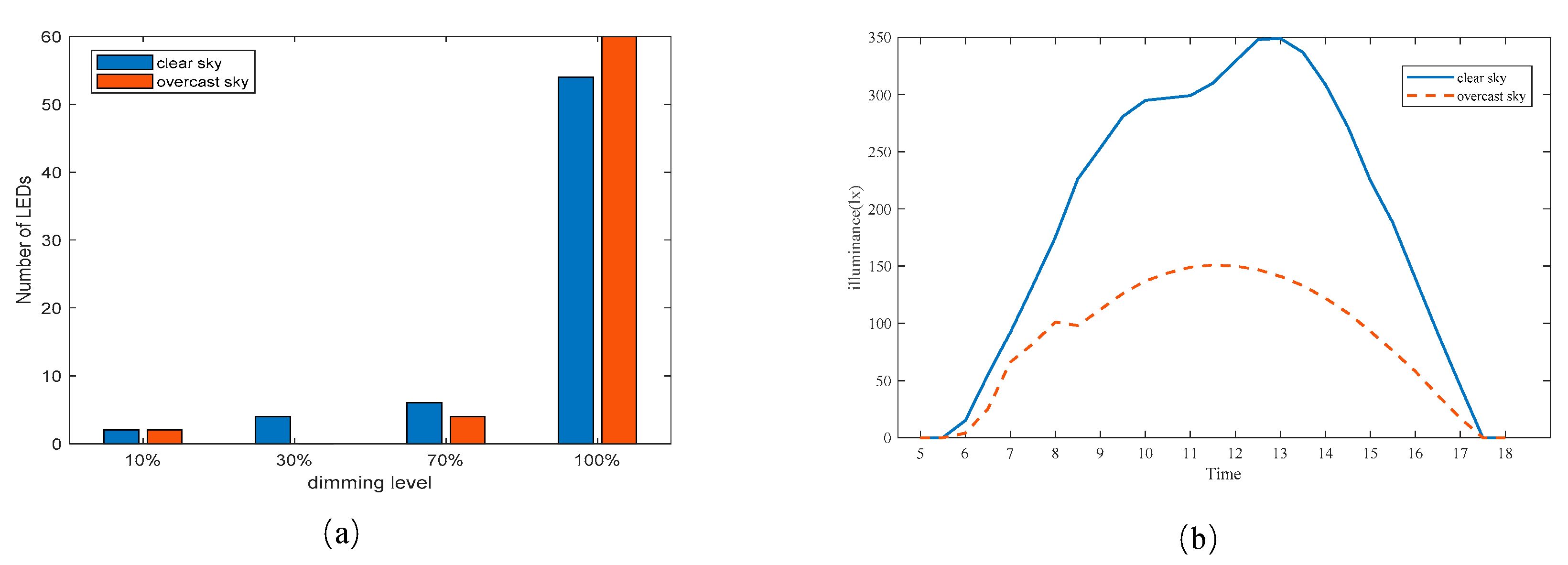
The performance of daylight harvesting was correlated with the weather condition. The distribution of the dimming levels of luminaries at 10:00 a.m. in 2 days corresponding to two types of weather conditions, i.e., clear sky and overcast sky, are presented in Figure 15a. Compared to the overcast sky, under clear sky conditions, there were more LEDs with lower dimming levels. As shown in Figure 15b, the values of the light sensors exceeded 180 lx in more than 65% of the working hours during the day time, which was from 9 a.m. to 6 p.m., which indicated that the dimming levels of LEDs were 30% in the PZ and 70% in the SZ; in contrast, the values of the light sensors were between 125 and 180 lx in about 45% of the working hours and less than 125 lx in the rest of the time. Although the daylighting was good under a clear sky, most of the luminaires were dimmed to 100%, as shown in Figure 15a. There were two reasons for high dimming levels. First, Zone A and 45% of worktables in Zone B were in the middle of the floor plan, where the daylight condition was poor. Second, the requirement for illuminance on the desktop was 500 lx leading to a small PZ. If the requirement of illuminance was reduced to 300 lx, the new PZ could be expanded to the same size as the old secondary zone, and the SZ could be expanded too.
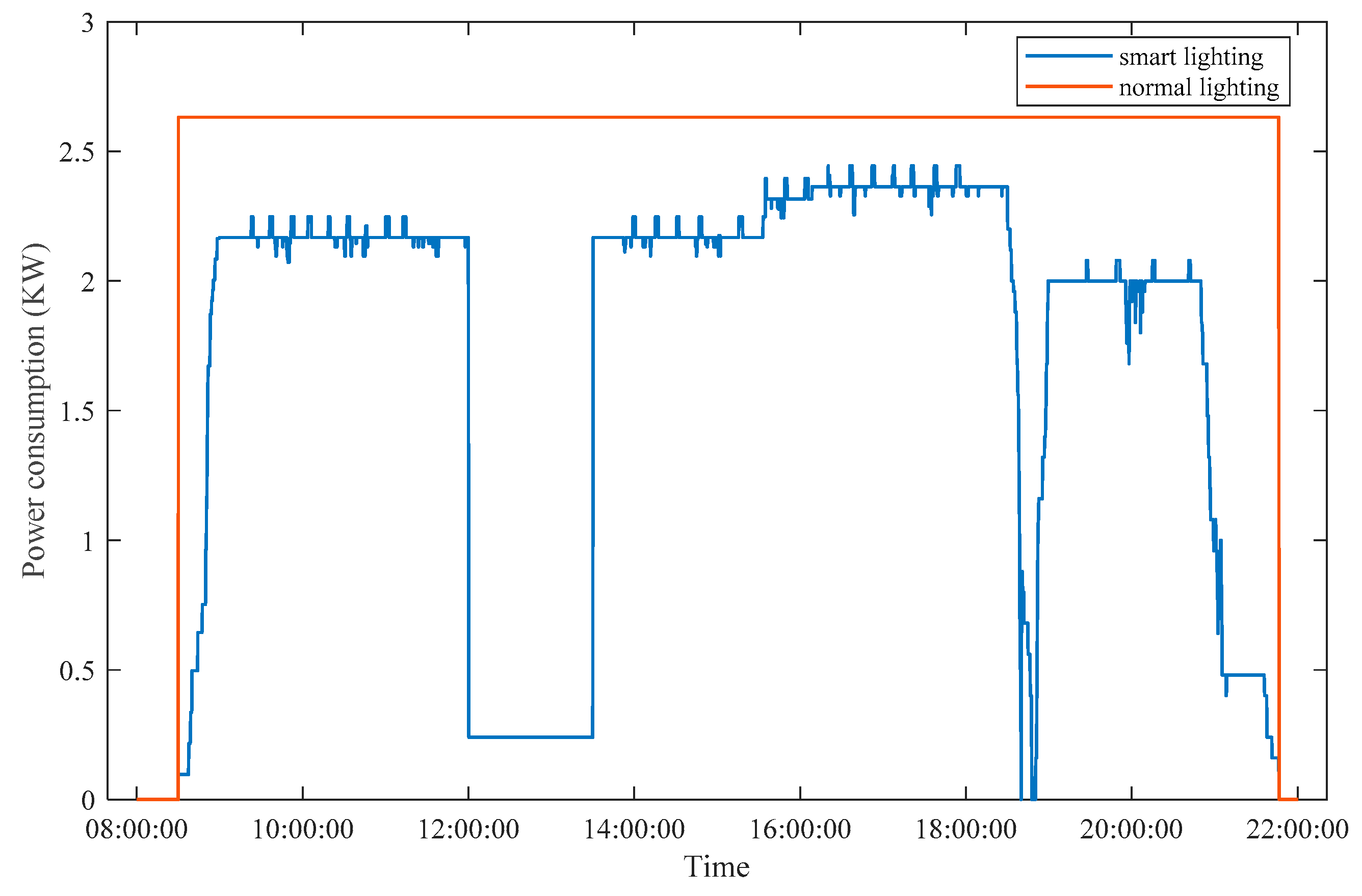
The power consumption of the proposed smart lighting system was evaluated and compared with that of the normal lighting system where lights were switched on manually at the beginning of the day, i.e., when the first worker entered the room, and switched off at the end of the day, i.e., when the last worker left the room. The power consumption was calculated under the assumption that the power consumption of each LED was proportional to the dimming level collected by the gateway in every 15 s. The power consumption from 8 a.m. to 10 p.m. in 1 day is shown in Figure 16. The overtime was after 6:30 p.m. in the evening. As there was a need to use neighboring luminaires to meet the required illuminance value of 500 lx, luminaires were turned on even when they were unoccupied, but their neighbors were occupied. Therefore, from 9 a.m. to 6 p.m., the power consumption of the proposed system was relatively stable, and the power savings were low, as shown in Figure 16. Moreover, about 70% of the staff stayed after 6:30 p.m. With the decrease in the staff number in the office, energy savings owing to the occupancy detection increased. Nearly 36% of average power consumption was saved using the proposed system compared to the normal lighting system.
5. Discussion
In this study, a smart lighting system is proposed to control the indoor illuminance level. The proposed system includes distributed wireless sensing networks and a sensing module consisting of occupancy sensors and ambient light sensors. The proposed system is verified by the experiments in two scenarios, i.e., a metro station and an office room, and the results show that the proposed system is robust enough in practical environments. The performance of occupancy detection of the proposed system is also verified experimentally. The energy savings of the proposed system are also evaluated in the scenario of the metro station, where energy consumption is recorded, and in the scenario of the office room, where power consumption is calculated using dimming levels.
In the scenario of the metro station, the relative energy saving of the proposed system is about 45% compared to the normal lighting system. The energy savings are achieved by dimming the LEDs down to a 10% level when no occupant is detected. The results show that the people flow density influences the value of the energy savings. Juntunen et al. [40] presented a similar lighting control strategy designed for street lighting infrastructure and achieved 60–77% savings compared to a 100% dimming level at the dark time of the day. However, their savings were based on the simulation results obtained using the presence data and sunrise and sunset times from the weather data bank. On the contrary, in this study, a comparison experiment is conducted and the energy consumption is measured in a real scenario. Moreover, the considered people flow density is also different because our system was installed in a metro station in China while theirs was installed on a pedestrian road in Helsinki. Besides energy savings, when designing the lighting system, it is important to consider the user experience, including safety and comfort. For instance, in this study, the illuminated area is expanded so that a user cannot detect the change in lighting level around him/her. This increases the system cost and reduces the interest in investing the new technologies. This problem can be resolved by careful selection of the location where the smart lighting system is installed. For instance, metro stations with a low passenger flow density are more suitable for the installation of the proposed system than those with a moderate or high passenger flow density. Moreover, the sensing module can be extended to include other sensor types, such as Bluetooth, to provide new functions and reduce the cost.
The results show that in the scenario of the office room, the energy savings were influenced by multiple factors, including weather, desired illuminance level, location of worktables, and the number of staff in the room. The power consumption savings were about 36%, which was lower than the power savings of 40% that was reported in [43] at the same desired illuminance level, i.e., 500 lx. There are two possible reasons for this difference. First, the overall conditions of the office room for daylight harvesting were not favorable, as 45% of worktables were in the middle of the floor plan where the distance to windows was far, and the illuminance of daylight was low. Second, the open-loop lighting controller was used, and the rule base was designed for this controller. Compared to the closed-loop controller, the advantages of the controller used in this work are less amount of computation, faster reaction to the change in environmental conditions, and lower cost of manufacturing and maintenance. However, the main drawback is a lack of optimization of energy consumption. For instance, the PZ and SZ for daylight harvesting are unchanging in this work, which makes it impossible to fully utilize daylight as space in a room getting more sunlight varies with time from sunrise to sunset. When the desired illuminance level decreases, the optimization of the dimming level of each luminaire becomes important to energy savings.
As the proposed lighting control system is based on open-loop controller in which control rules are designed to determine the dimming level, when the system is applied to a new commercial building, schedules (occupant pattern), artificial light contribution to the value of ambient light sensor, the partition for daylight harvesting and harvesting rules in Equation (3) need to be modified in a supplied software. Compared with closed-loop controller, open-loop controller in this system is less precise and less flexible. However, in wireless networks, an increase in settling time of luminaires due to packet losses was found when using a central and close-loop controller [9]. Contrarily, settling time in the proposed system is less as a result of the distributed and open-loop controller. Moreover, the proposed system is easier to deploy and cheaper in comparison to a wired system, especially for building retrofits. A sensing module and a LED driver are attached to a LED luminaire if the luminaire is nondimmable. Otherwise, only a sensing module is needed. However, when the proposed system is deployed in a public place, an important challenge is the security of ZigBee protocol used in the WSN for lighting control and countermeasures for attacks to ZigBee networks need to be devised [44,45].
The experimental results show that the proposed smart lighting system can realize occupancy-driven and daylight harvesting lighting control and reduce energy consumption in practical environments. Nevertheless, the following limitations need to be underlined. First, in the scenario of the metro station, there are no standards on occupancy-based lighting control. In addition, the impact of the proposed smart lighting system on passengers’ safety and comfortability is not quantitatively studied in this work. The lighting controller can be improved by combining dimming levels and user reactions. Second, in the scenario of the office room, the rule base, which is the core of the lighting controller, is designed only considering the location of luminaries, schedule, and occupancy, but more factors related to the energy consumption, such as seasons, hours, and weather information, should be analyzed and integrated into lighting control rules. Third, control designs that account for electric blinds are not included in the proposed system. Blinds are often used to reduce glare and improve thermal comfort. Meanwhile, the use of blinds has an effect on the illuminance of daylight. Integrated lighting control algorithms that take into consideration illuminance, light uniformity, and temperature are needed to minimize energy consumption. Fourth, the cost of the proposed system is not quantitatively analyzed, which includes cost in design, manufacture, installation, and maintenance. Whether achieved energy savings would quickly cover the cost of the smart lighting system is important for the development of the system. Our future work will address the mentioned problems and will focus on improving the proposed smart lighting system using the Internet of Things (IoT) and deep learning techniques.
Author Contributions
Conceptualization, Y.C. and C.F.; methodology, Y.C. and J.Y.; software, C.F.; validation, Y.C. and L.Z.; formal analysis, Y.C. and C.F.; investigation, Y.C.; resources, C.F.; data curation, J.Y.; writing—original draft preparation, Y.C.; writing—review and editing, L.Z. and J.Y.; visualization, C.F.; supervision, J.Y.; project administration, J.Y.; funding acquisition, Y.C. All authors have read and agreed to the published version of the manuscript.
Funding
This research was funded by the National Natural Science Foundation of China, grant number 71601047 and China Postdoctoral Science Foundation, grant number 2015M581706.
Conflicts of Interest
The authors declare no conflict of interest.
References
- Allouhi, A.; El Fouih, Y.; Kousksou, T.; Jamil, A.; Zeraouli, Y. Energy consumption and efficiency in buildings: Current status and future trends. J. Clean. Prod. 2015, 109, 118–130. [Google Scholar] [CrossRef]
- IEA. Transition to Sustainable Buildings; IEA: Paris, France, 2013. [Google Scholar]
- Lowry, G. Energy saving claims for lighting controls in commercial buildings. Energy Build. 2016, 133, 489–497. [Google Scholar] [CrossRef]
- Chiesa, G.; Di Vita, D.; Ghadirzadeh, A.; Herrera, A.H.M.; Rodriguez, J.C.L. A fuzzy-logic IoT lighting and shading control system for smart buildings. Autom. Constr. 2020, 120, 103397. [Google Scholar] [CrossRef]
- Sun, F.; Yu, J. Indoor intelligent lighting control method based on distributed multi-agent framework. Optik 2020, 213, 164816. [Google Scholar] [CrossRef]
- Imam, M.H.T.; Afshari, S.; Mishra, S. Smart lighting control systems. In Intelligent Building Control Systems; Wen, J., Mishra, S., Eds.; Springer International Publishing: Cham, Switzerland, 2018; pp. 221–251. [Google Scholar]
- Cho, Y.; Seo, J.; Lee, H.; Choi, S.; Choi, A.; Sung, M.; Hur, Y. Platform design for lifelog-based smart lighting control. Build. Environ. 2020, 185, 107267. [Google Scholar] [CrossRef]
- Pandharipande, A.; Li, S. Ligh-harvesting wireless sensors for indoor lighting control. IEEE Sens. J. 2013, 13, 4599–4606. [Google Scholar] [CrossRef]
- Peruffo, A.; Pandharipande, A.; Caicedo, D.; Schenato, L. Lighting control with distributed wireless sensing and actuation for daylight and occupancy adaptation. Energy Build. 2015, 97, 13–20. [Google Scholar] [CrossRef]
- Liu, J.; Zhang, W.; Chu, X.; Liu, Y. Fuzzy logic controller for energy savings in a smart LED lighting system considering lighting comfort and daylight. Energy Build. 2016, 127, 95–104. [Google Scholar] [CrossRef]
- Labeodan, T.; de Bakker, C.; Rosemann, A.; Zeiler, W. On the application of wireless sensors and actuators network in existing buildings for occupancy detection and occupancy-driven lighting control. Energy Build. 2016, 127, 75–83. [Google Scholar] [CrossRef] [Green Version]
- Wen, Y.-J.; Agogino, A.M. Personalized dynamic design of networked lighting for energy-efficiency in open-plan offices. Energy Build. 2011, 43, 1919–1924. [Google Scholar] [CrossRef]
- Nagy, Z.; Yong, F.Y.; Frei, M.; Schlueter, A. Occupant centered lighting control for comfort and energy efficient building operation. Energy Build. 2015, 94, 100–108. [Google Scholar] [CrossRef]
- Caicedo, D.; Pandharipande, A. Distributed illumination control with local sensing and actuation in networked lighting systems. IEEE Sens. J. 2013, 13, 1092–1104. [Google Scholar] [CrossRef] [Green Version]
- Pandharipande, A.; Caicedo, D. Smart indoor lighting systems with luminaire-based sensing: A review of lighting control approaches. Energy Build. 2015, 104, 369–377. [Google Scholar] [CrossRef]
- Delvaeye, R.; Ryckaert, W.; Stroobant, L.; Hanselaer, P.; Klein, R.; Breesch, H. Analysis of energy savings of three daylight control systems in a school building by means of monitoring. Energy Build. 2016, 127, 969–979. [Google Scholar] [CrossRef]
- Van de Meugheuvel, N.; Pandharipande, A.; Caicedo, D.; van den Hof, P.P.J. Distributed lighting control with daylight and occupancy adaption. Energy Build. 2014, 75, 321–329. [Google Scholar] [CrossRef]
- Magno, M.; Polonelli, T.; Benini, L.; Popovici, E. A low cost, highly scalable wireless sensor network solution to achieve smart LED light control for green buildings. IEEE Sens. J. 2015, 15, 2963–2973. [Google Scholar] [CrossRef]
- Li, S.; Pandharipande, A. Networked illumination control with distributed light-harvesting wireless sensors. IEEE Sens. J. 2015, 15, 1662–1669. [Google Scholar] [CrossRef]
- Papatsimpa, C.; Linnartz, J.P.M.G. Propagating sensor uncertainty to better infer office occupancy in smart building control. Energy Build. 2018, 179, 73–82. [Google Scholar] [CrossRef]
- Jia, R.; Jin, M.; Chen, Z.; Spanos, C. Soundloc: Accurate room-level indoor localization using acoustic signatures. In Proceedings of the IEEE International Conference on Automation Science and Engineering (IEEE CASE 2015), Gothenburg, Sweden, 24–28 August 2015; pp. 186–193. [Google Scholar]
- Zou, H.; Zhou, Y.; Jiang, H.; Chien, S.-C.; Xie, L.; Spanos, C.J. WinLight: A WiFi-based occupancy-driven lighting control system for smart building. Energy Build. 2018, 158, 924–938. [Google Scholar] [CrossRef]
- Han, K.H.; Zhang, J. Energy-saving building system integration with a smart and low-cost sensing/control network for sustainable and healthy living environments: Demonstration case study. Energy Build. 2020, 214, 109861. [Google Scholar] [CrossRef]
- Ahmad, J.; Larijani, H.; Emmanuel, R.; Mannion, M.; Javed, A. Occupancy detection in non-residential buildings-A survey and novel privacy preserved occupancy monitoring solution. Comput. Inform. 2020, in press. [Google Scholar] [CrossRef]
- Wang, H.; Li, C.; Zhang, Y.; Liu, Z.; Hui, Y.; Mao, G. A scheme on pedestrian detection using multi-sensor data fusion for smart roads. In Proceedings of the 2020 IEEE 91st Vehicular Technology Conference (VTC2020-Spring), Antwerp, Belgium, 25–28 May 2020; pp. 1–5. [Google Scholar]
- Fraden, J. Occupancy and motion detectors. In Handbook of Modern Sensors; Springer: New York, NY, USA, 2010; pp. 247–278. [Google Scholar]
- Dong, B.; Andrews, B.; Lam, K.P.; Höynck, M.; Zhang, R.; Chiou, Y.-S.; Benitez, D. An information technology enabled sustainability test-bed (ITEST) for occupancy detection through an environmental sensing network. Energy Build. 2010, 42, 1038–1046. [Google Scholar] [CrossRef]
- Gao, C.; Li, P.; Zhang, Y.; Liu, J.; Wang, L. People counting based on head detection combining Adaboost and CNN in crowded surveillance environment. Neurocomputing 2016, 208, 108–116. [Google Scholar] [CrossRef]
- Sun, K.; Zhao, Q.; Zou, J. A review of building occupancy measurement systems. Energy Build. 2020, 216, 109965. [Google Scholar] [CrossRef]
- Chen, Z.; Jiang, C.; Xie, L. Building occupancy estimation and detection: A review. Energy Build. 2018, 169, 260–270. [Google Scholar] [CrossRef]
- Yang, Z.; Li, N.; Becerik-Gerber, B.; Orosz, M. A multi-sensor based occupancy estimation model for supporting demand driven hvac operations. In Proceedings of the 2012 Symposium on Simulation for Architecture and Urban Design, Orlando, Florida, 26–30 March 2012. Article No. 2. [Google Scholar]
- Amayri, M.; Arora, A.; Ploix, S.; Bandhyopadyay, S.; Ngo, Q.-D.; Badarla, V.R. Estimating occupancy in heterogeneous sensor environment. Energy Build. 2016, 129, 46–58. [Google Scholar] [CrossRef]
- Zikos, S.; Tsolakis, A.; Meskos, D.; Tryferidis, A.; Tzovaras, D. Conditional Random Fields-based approach for real-time building occupancy estimation with multi-sensory networks. Autom. Constr. 2016, 68, 128–145. [Google Scholar] [CrossRef]
- Wagiman, K.R.; Abdullah, M.N.; Hassan, M.Y.; Radzi, N.H.M.; Bakar, A.H.A.; Kwang, T.C. Lighting system control techniques in commercial buildings: Current trends and future directions. J. Build. Eng. 2020, 31, 101342. [Google Scholar] [CrossRef]
- Guo, X.; Tiller, D.K.; Henze, G.P.; Waters, C.E. The performance of occupancy-based lighting control systems: A review. Light. Res. Technol. 2010, 42, 415–431. [Google Scholar] [CrossRef]
- Wagiman, K.R.; Abdullah, M.N.; Hassan, M.Y.; Radzi, N.H.M. A review on sensing-based strategies of interior lighting control system and their performance in commercial buildings. Indones. J. Electr. Eng. Comput. Sci. 2019, 16, 208–215. [Google Scholar] [CrossRef]
- De Bakker, C.; Aries, M.; Kort, H.; Rosemann, A. Occupancy-based lighting control in open-plan office spaces: A state-of-the-art review. Build. Environ. 2017, 112, 308–321. [Google Scholar] [CrossRef]
- Wang, L.; Zou, X.; Meng, Q.; Song, X. An optimal strategy for the deployment of sensor nodes in green buildings. In Proceedings of the Six International Conference on Intelligent Control and Information Processing, Wuhan, China, 26–28 November 2015; pp. 209–213. [Google Scholar]
- Norouziasl, S.; Jafari, A.; Wang, C. Analysis of lighting occupancy sensor installation in building renovation using agent-based modeling of occupant behavior. In Proceedings of the ASCE International Conference on Computing in Civil Engineering 2019, Atlanta, Georgia, 17–19 June 2019; pp. 593–601. [Google Scholar]
- Juntunen, E.; Sarjanoja, E.-M.; Eskeli, J.; Pihlajaniemi, H.; Österlund, T. Smart and dynamic route lighting control based on movement tracking. Build. Environ. 2018, 142, 472–483. [Google Scholar] [CrossRef]
- Oviedo, R.M.; Ramos, F.; Gormus, S.; Kulkarni, P.; Sooriyabandara, M. A comparison of centralized and distributed monitoring architectures in the smart grid. IEEE Syst. J. 2013, 7, 832–844. [Google Scholar] [CrossRef]
- Seyedolhosseini, A.; Masoumi, N.; Modarressi, M.; Karimian, N. Daylight adaptive smart indoor lighting control method using artificial neural networks. J. Build. Eng. 2020, 29, 101141. [Google Scholar] [CrossRef]
- Kandasamy, N.K.; Karunagaran, G.; Spanos, C.; Tseng, K.J.; Soong, B.-H. Smart lighting system using ANN-IMC for personalized lighting control and daylight harvesting. Build. Environ. 2018, 139, 170–180. [Google Scholar] [CrossRef] [Green Version]
- Li, H.; Jia, Z.; Xue, X. Application and analysis of ZigBee security services specification. In Proceedings of the 2010 Second International Conference on Networks Security, Wireless Communications and Trusted Computing, Wuhan, China, 24–25 April 2010; pp. 494–497. [Google Scholar]
- Olawumi, O.; Haataja, K.; Asikainen, M.; Vidgren, N.; Toivanen, P. Three practical attacks against ZigBee security: Attack scenario definitions, practical experiments, countermeasures, and lessons learned. In Proceedings of the 2014 14th International Conference on Hybrid Intelligent Systems, Hawally, Kuwait, 14–16 December 2014; pp. 199–206. [Google Scholar]
Figure 1.
The architecture of the smart lighting system: (a) a wireless sensing module, (b) a LED luminaire controlled by a sensing module through LED driver, and (c) a wireless mesh network composed of sensing modules and a gateway.
Figure 1.
The architecture of the smart lighting system: (a) a wireless sensing module, (b) a LED luminaire controlled by a sensing module through LED driver, and (c) a wireless mesh network composed of sensing modules and a gateway.

Figure 2.
A simple example of lighting control according to occupancy information with neighbor assistance.
Figure 2.
A simple example of lighting control according to occupancy information with neighbor assistance.

Figure 3.
ZigBee network topologies: (a) star, (b) tree, and (c) mesh.

Figure 4.
Flowchart of the data fusion method with passive infrared (PIR) and microwave sensors.

Figure 5.
Flowchart of the neighbor-aided illumination control of node m.

Figure 6.
The layout of the office space.

Figure 7.
Subdivision of Zone B according to the distance to the window.

Figure 8.
Two walking scenarios with lighting control strategies: (a) walking straight forward and (b) passing an intersection. Beyond the brightened area, the light-emitting diodes (LEDs) are at the dimming level of 10%.
Figure 8.
Two walking scenarios with lighting control strategies: (a) walking straight forward and (b) passing an intersection. Beyond the brightened area, the light-emitting diodes (LEDs) are at the dimming level of 10%.

Figure 9.
Deployment of the proposed system in the concourse level of the metro station. Comparison experiments were performed in Zones 1 and 2, which were symmetric and had the same number of LEDs. The smart lighting system was implemented in zone 1, while the normal lighting system was used in zone 2.

Figure 10.
PIR activations in a 24-h period.

Figure 11.
Comparison of dimming levels of a luminaire.

Figure 12.
Comparison of energy consumption.

Figure 13.
Floor plan and layout of luminaires: (a) floor plan of the office and (b) layout of luminaires, each of which was equipped with a sensing module.
Figure 13.
Floor plan and layout of luminaires: (a) floor plan of the office and (b) layout of luminaires, each of which was equipped with a sensing module.

Figure 14.
Division of the largest office room for smart light control: (a) Zones A, B, and C in the control strategy and (b) PZ and SZ for daylight harvesting.
Figure 14.
Division of the largest office room for smart light control: (a) Zones A, B, and C in the control strategy and (b) PZ and SZ for daylight harvesting.

Figure 15.
The effect of the weather conditions on daylight harvesting: (a) the distribution of dimming levels at 10:00 a.m. under a clear sky and overcast sky conditions and (b) the values of the light sensors at different times.
Figure 15.
The effect of the weather conditions on daylight harvesting: (a) the distribution of dimming levels at 10:00 a.m. under a clear sky and overcast sky conditions and (b) the values of the light sensors at different times.

Figure 16.
Lighting power consumptions during office hours and overtime hours.


Table 1.
Specifications of the sensors installed in the sensing module.
| Sensor | Specification |
|---|---|
| PIR sensor (RE46BN-P) | Maximum sensing angle: 132° Operating wavelength: 5–14 μm Operating temperature range: −30 to 70 °C |
| Microwave doppler sensor (MS-220) | Maximum sensing angle: 360° Sensing distance: adjustable Operating temperature range: −35 to 75 °C |
| Illuminance sensor (BH1750FVI) | Detection range: 0–65 525 lx Operating temperature range: 40–85 °C |
Table 2.
Sensor layout.
| Zone | Sensor Type |
|---|---|
| A | PIR sensors |
| B | Light sensors (nearest to the windows) PIR sensors and microwave sensors |
| C | PIR sensors and microwave sensors |
Table 3.
Lighting control rules.
| Stage | Time | Rule |
|---|---|---|
| 1: Off-duty | 10 p.m. the day before to 6 a.m. next day |
|
| 2: Before work | 6 a.m. to 9 a.m. |
|
| 3: On-duty | 9 a.m. to noon |
|
| 4: Lunch break | noon to 1 p.m. |
|
| 5: On-duty | 1:30 p.m. to 6:30 p.m. |
|
| 6: Work overtime | 6:30 p.m. to 10 p.m. |
|
Table 4.
Specifications of the light-emitting diodes (LED) luminaires in the comparison experiment.
| Subzone | Type | Power (W) | Number of Luminaires |
|---|---|---|---|
| 1 | Grille light | 16× | 10 |
| 2 | Grille light | 16× | 13 |
Table 5.
Energy consumption and energy saving.
| Zone | Time | Energy Consumption (KWh) | Energy Savings (%) | |
|---|---|---|---|---|
| Normal CONTROL | Smart Control | |||
| Subzone 1 | 5 h | 1.25 | 0.97 | 22.4% |
| 3 days | 14.72 | 7.87 | 46.54% | |
| 23 days | 103.14 | 87.28 | 15.38% | |
| Subzone 2 | 5 h | 1.72 | 0.91 | 47.09% |
| 3 days | 19.34 | 6.43 | 66.75% | |
| 23 days | 199.07 | 56.72 | 71.51% | |
Table 6.
Specifications of the luminaires in scenario 2.
| Type | Power (W) | Number of Luminaires |
|---|---|---|
| Line light | 40 | 92 |
| Downlight | 12 | 85 |
| Binocular downlight | 12× | 24 |
Publisher’s Note: MDPI stays neutral with regard to jurisdictional claims in published maps and institutional affiliations. |
© 2020 by the authors. Licensee MDPI, Basel, Switzerland. This article is an open access article distributed under the terms and conditions of the Creative Commons Attribution (CC BY) license (http://creativecommons.org/licenses/by/4.0/).
Share and Cite
MDPI and ACS Style
Cheng, Y.; Fang, C.; Yuan, J.; Zhu, L. Design and Application of a Smart Lighting System Based on Distributed Wireless Sensor Networks. Appl. Sci. 2020, 10, 8545. https://0-doi-org.brum.beds.ac.uk/10.3390/app10238545
AMA Style
Cheng Y, Fang C, Yuan J, Zhu L. Design and Application of a Smart Lighting System Based on Distributed Wireless Sensor Networks. Applied Sciences. 2020; 10(23):8545. https://0-doi-org.brum.beds.ac.uk/10.3390/app10238545
Chicago/Turabian StyleCheng, Yusi, Chen Fang, Jingfeng Yuan, and Lei Zhu. 2020. "Design and Application of a Smart Lighting System Based on Distributed Wireless Sensor Networks" Applied Sciences 10, no. 23: 8545. https://0-doi-org.brum.beds.ac.uk/10.3390/app10238545
Note that from the first issue of 2016, this journal uses article numbers instead of page numbers. See further details here.