Article

The Role of Crystalline Orientation in the Formation of Surface Patterns on Solids Irradiated with Femtosecond Laser Double Pulses

1
Institute of Electronic Structure and Laser (IESL), Foundation for Research and Technology (FORTH), N. Plastira 100, Vassilika Vouton, 70013 Heraklion, Crete, Greece
2
Laboratoire de Physique des Lasers, CNRS UMR 7538, Université Sorbonne Paris NORD, 93430 Villetaneuse, France
3
Laboratoire des Sciences des Procédés et des Matériaux, CNRS, Université Sorbonne Paris NORD, 93430 Villetaneuse, France
*
Author to whom correspondence should be addressed.
Submission received: 12 November 2020 / Revised: 2 December 2020 / Accepted: 7 December 2020 / Published: 9 December 2020
(This article belongs to the Special Issue Multiscale Modelling of Laser-Induced Phenomena on Solids)

Abstract

:

Featured Application

Laser processing appears to be a scalable method to fabricate highly ordered and complex biomimetic surface structures which can be used in an abundance of industrial applications. On the other hand, a multiscale theoretical approach represents a powerful tool that can provide significant information for designing materials. The approach is aimed to offer a cost-effective method towards minimising the use of trial and error approaches to reduce a large number of experiments towards fabricating application-based patterns.

Abstract

A theoretical investigation of the underlying ultrafast processes upon irradiation of rutile TiO2 of (001) and (100) surface orientation with femtosecond (fs) double pulsed lasers was performed in ablation conditions, for which, apart from mass removal, phase transformation and surface modification of the heated solid were induced. A parametric study was followed to correlate the transient carrier density and the produced lattice temperature with the laser fluence, pulse separation and the induced damage. The simulations showed that both temporal separation and crystal orientation influence the surface pattern, while both the carrier density and temperature drop gradually to a minimum value at temporal separation equal to twice the pulse separation that remain constant at long delays. Carrier dynamics, interference of the laser beam with the excited surface waves, thermal response and fluid transport at various pulse delays explained the formation of either subwavelength or suprawavelength structures. The significant role of the crystalline anisotropy is illustrated through the presentation of representative experimental results correlated with the theoretical predictions.

1. Introduction

The impact of the employment of ultra-short pulsed laser sources in material processing has received considerable attention due to its important applications, in particular in industry and medicine [1,2,3,4,5,6,7,8,9,10]. Due to its unique advantages, the laser-assisted processing method (LAPM) emerged as a significant tool for precise fabrication at nano- and micro-scales.
Laser-induced periodic surface structures (LIPSS) on solids is one type of surface patterns that has been explored extensively, becausethe features of the produced structures provide impressive properties that can be used in many applications including microfluidics [1,11], tribology [12,13,14], tissue engineering [11,15] and advanced optics [16,17]. There exists a wealth of reports related to the elucidation of the underlying physical processes for the formation of these structures in a variety of laser conditions (i.e., fluence, pulse duration, laser wavelength, pulse separation, polarisation state, energy dose) and in different materials [17,18,19,20,21]. Some of the most representative types of LIPSS are the coined low-spatial-frequency (LSFL) ripples [22,23], high-spatial-frequency (HSFL) ripples [18,24], grooves [20,25] and spikes [25]. A series of multiphysical phenomena were analysed to explain the physical origins of the LIPSS formation [26,27,28,29,30]. More specifically, various theoretical models have been proposed to interpret the production of periodic structures: interference of the incident wave with an induced scattered wave [31,32,33], or with a surface plasmon wave (SP) [21,22,34,35,36,37], or due to self-organisation mechanisms [38].
Although, the formation of LIPSS at long time scales is closely related to a phase transformation, one process that undoubtedly has to be investigated is the response of the material at short time scales. More specifically, as stated above, the impact of electromagnetic effects and plasma contribution [39], surface plasmon excitation [22,34], wave interference effects [40] are some of the processes that need to be explored when the material is in a non-equilibrium state. Therefore, the ultrafast dynamics of the excited carriers is an important ingredient that greatly influences the LIPSS periodicities. To provide a comprehensive elucidation of the ultrafast dynamics of the charge carriers, it is important to elaborate on the influence of the laser parameters on the excited plasma characteristics and then, on the thermal response of a material. The existing multiscale models and experimental studies have successfully provided a detailed analysis of the physical mechanisms that lead to a plethora of structural effects [22,41,42,43,44,45]. In principle, the laser beam parameters determine the first steps of the processes because energy absorption and relaxation processes influence significantly the material heating [43].
Nevertheless, although for many semiconducting materials, the physical mechanism that describes ultrafast dynamics is well-established and the theoretical model works effectively in various conditions, there is still a missing picture for some types of semiconductors such as TiO2 and more specifically for materials with different crystal orientations. In particular, in a previous report, a parametric study of the laser conditions and the induced structures revealed that there is a difference in the response of the material if crystals with orientation (001) and (100) are irradiated [46,47,48]. In that study, it was emphasised that a key difference between the two crystal orientations is the effective electron mass (apart from the fact that interactions between atoms, thermomechanical response and melting are strongly affected by the interatomic distance which varies with the crystal orientation [49]); the discrepancy of the optical mass (measured or calculated in precious reports [47,48,50,51,52,53,54]) affects optical parameters of the material, amount of the absorbed energy and, eventually, thermal response of the system that is also projected on the type of LIPSS that are formed [46]. Nevertheless, despite these early results and conclusions, a more elaborated approach is required to evaluate more explicitly the impact of crystal orientation in the energy absorption; it is noted that TiO2 is a uniaxial birefringent material with optical axis parallel to direction (001). Therefore, in the case of an irradiation under normal incidence of the face (001), the electromagnetic wave of laser propagates according to the normal refractive index n ,   k . On the other hand, in the case of irradiation under normal incidence of the face (100) or (110), the optical axis lies in the plane of the surface. Thus, there are waves propagating according to refractive indexes n ,   k and n ,   k respectively. Furthermore, although, the difference in the optical response of the system induced by the distinct crystal orientation for irradiation with femtosecond pulses has been investigated [46], no previous study has been conducted to explore the impact of the shape of the laser pulse and more specifically of temporarily separated pulses. In previous reports, the effect of the irradiation of various types of materials with temporarily separated pulses has been investigated which revealed a significant variation in the ultrafast dynamics, thermal response of the material and finally, changes in the LIPSS frequencies [29,36,55]. Therefore, and given the role of the crystal orientation, a detailed description of the ultrafast dynamics resulting from irradiating semiconductors with different crystal orientation with double pulses of variable temporal separation would provide significant information. More specifically, elucidation of this issue is of paramount importance, firstly, to elucidate the underlying multiscale physical mechanisms of laser-matter interaction and secondly to associate the resulting thermal effects with the induced surface patterns.
To this end, we present a detailed theoretical approach that describes the ultrafast dynamics in rutile TiO2 [22,26,30,56,57,58], to account firstly, for excitation and electron-phonon relaxation upon irradiation of TiO2 in two crystal orientations with periodic ultrashort laser double-pulses separated by a temporal delay from zero to tens of picoseconds (Section 2). The details of an experimental protocol that has been developed is described in Section 3, while a thorough analysis of results and validation of the theoretical model are presented in Section 4 by discussing the ultrafast dynamics, thermal response and induced surface modification predictions. Concluding remarks follow in Section 5.

2. Theoretical Model

2.1. Ultrafast Dynamics

It is known that during laser irradiation of a material, various physical processes occur on a femtosecond timescale. In this work, excitation of a semiconducting material, rutile TiO2 with (001) and (100) surface orientation was considered through a laser beam of wavelength λL = 248 nm that corresponds to photon energies equal to ~5 eV which is higher than the band gap of the material (~3.0 eV, at 300 K); thus, it is assumed that predominantly one- and (secondly and with a substantially smaller probability) two-photon absorption mechanisms contribute to excitation of the charge carriers in the valence and conduction bands, while higher order photon processes are less likely to occur. Furthermore, linear free carrier photon absorption on the intraband transitions are possibly increase the carrier energy (but not the carrier density), while Auger recombination and impact ionization processes lead to a decrease and increase, respectively, of the number of carriers in the conduction band.
The relaxation time approximation to Boltzmann’s transport equation [22,26,30,56,57,58] is employed to determine the spatial ( r   =   x , y , z , in Cartesian coordinates) and temporal dependence (t) of the carrier density number, carrier energy and lattice energy; more specifically, the following set of coupled energy and particle balance equations are used to describe the temporal variation of the carrier density number Nc, carrier temperature Tc and lattice temperature TL:
C c T c t = C c τ c l T c T L + S ( r , t ) C L T L t = K L T L + C c τ c l T c T L N c t = α S P A ω L I ( r , t ) + β T P A 2 ω L I 2 ( r , t ) γ N c 3 + θ N c
where Cc (CL) is the carrier (lattice) specific heat, KL corresponds to the lattice heat conductivity, ω L stands for the photon energy and α S P A and β T P A correspond to the single and two-photon absorption coefficients, respectively. Cc is provided by the expression C c   =   3 N c k B , where k B stands for the Boltzmann constant. The lattice specific heat and heat conductivity for TiO2 are CL = 690 J Kgr−1 K−1 [59] and KL = 13 Wm−1 K−1 [60], respectively. At λL = 248 nm, α S P A 10 6   ×   exp T L / 300 cm−1 [61] while β T P A 37 cm/GW [46,62]. In Equation (1), τc-l is the carrier-phonon energy scattering time which is derived from 1 / τ c l 10 4 N c 1 / 3 s−1 [50]. Finally, γ is the coefficient for Auger recombination (γ~10−32 cm6/s [63]) and θ is the impact ionization rate coefficient. In this work, an intensity dependent expression is used for the impact ionization parameter θ [33,64] (unlike an approximating formula used for other semiconductors and at higher laser wavelengths, i.e., ~ e E g / k B T c s−1, for Silicon at 800 nm [22,57].
θ = e 2 τ c I c ε 0 n m r E g ω L 2 τ c 2 + 1 2 m r / m e
In Equation (2), c is the speed of light, e is the electron charge, ε0 stands for the vacuum permittivity, mr (i.e., mr = 0.5me) is the reduced electron mass and n is the refractive index of the material, while I is the peak intensity of the laser beam, and τc is the electron collision time. Based on previous reports [50], scattering rates for electron-hole and electron-electron collisions scale as N c and N c 1 / 3 , respectively, yielding approximate value τc~1 fs for TiO2 regardless of the orientation. This is the value that was used in this work. E g stands for the energy band gap of rutile TiO2 (~3 eV) [46]. The ‘source term’ that appears in the first equation in Equation (1) [22,56,57] is given by
S ( r , t ) = ( α S P A + α F C A ) I ( r , t ) + β T P A I 2 ( r , t ) N c t E g + 3 k B T c
In Equation (1), it is evident that carrier transport and carrier heat diffusion have been ignored. Although more rigorous expressions have been presented in previous works in which the contribution of those effects have been incorporated, reports showed that estimation of damage thresholds are not influenced significantly if those terms are ignored [56,57]. Similarly, for the sake of simplicity, it is assumed that the energy band gap does not vary significantly within the pulse.
The laser intensity I r , t in Equations (1)–(3) is obtained by considering the propagation loss due to one-photon, two-photon and free carrier absorption, respectively [22,26,30,36,57,65],
I ( r , t ) z = ( α S P A + α F C A ) I ( r , t ) β T P A I 2 ( r , t )
for a laser beam that is Gaussian, both temporally and spatially, the transmitted laser intensity on a flat surface for double pulses is provided by the following expression
I ( x , y , z = 0 , t ) = l n 2 E p ( 1 R ( z = 0 , t ) ) π τ p e 2 ( x 2 + y 2 ) R 0 2 e 4 ln 2 t 3 τ p τ p 2 + e 4 ln 2 t 3 τ p t d e l a y τ p 2
where 2Ep is the total fluence of the laser beam and τp is the pulse duration (i.e., full width at half maximum), R0 is the irradiation spot-radius (distance from the centre at which the intensity drops to 1/e2 of the maximum intensity, and R is the reflectivity while irradiation under normal incidence was assumed. The value of 3τp in the exponent in Equation (5) has been chosen to ensure that the intensity switches off at t = 0. The objective of the current work is to illustrate the impact of temporarily separated pulses, therefore, Equation (5) provides the total intensity of a double pulse of pulse delay equal to tdelay. In Equation (5), Cartesian coordinates have been used.
The calculation of the free carrier absorption coefficient and the reflectivity are derived from the dielectric parameter of the material (assuming also corrections due to band and state filling [66]), ε
ε = 1 + ε u n 1 1 N c N v e 2 N c ε 0 ω L 2 1 m o p t * 1 + i 1 ω L τ c  
where Nv stands for the valence band carrier density (~5 × 1023 cm−3 for TiO2) and εun is the dielectric parameter of the unexcited material at λL = 248 nm. In previous reports, the values of εun [67,68,69,70,71,72] and the optical mass m o p t * [47,48,50,51,52,53,54] were measured and estimated for both (001) and (100), respectively. As noted above, the dielectric parameter is expected to affect the energy absorption and therefore precise parameter values for m o p t * and εun are required. Based on the aforementioned works, the values ε u n 100   =   1.3 + 7.61 i , ε u n 001   =   3.09 + 6.95 i , m o p t * 100   =   6 m e , m o p t * 001   =   2 m e were used in the current study. For a flat surface, the reflectivity and free carrier absorption coefficients are computed through the following expressions
α F C A ( x , y , z , t ) = 2 ω L k e x t c R x , y , z = 0 , t = ( 1 n ) 2 + k e x t 2 ( 1 + n ) 2 + k e x t 2
where kext is the extinction coefficient of the material that is calculated from ε .

2.2. LSFL Formation

Among the physical processes that are aimed to account for the formation of LSFL structures, the most dominant scenarios are based on: (a) the interference of excited Surface Plasmon Polariton waves (SPP) with the incident beam [22,30,34,73], (b) the interference of the incident laser beam with induced surface scattered waves [40] or (c) the role of near field effects [39]. A key ingredient, though, for the excitation of SPP or surface scattered waves is the presence of an initial corrugation (for example, surface defects [22]). In regard to the first scenario that will be adopted in the current work, the interference of the incident and SPP leads to the formation of periodic ripples (LSFL) that are oriented perpendicularly to the electric field of the laser beam [18,21,22,31,32,33,74,75,76,77,78,79,80]; this is generated by a combination of multiscale processes such as the spatially periodic energy distribution (as a result of the interference of the incident beam and a surface wave), an induced characteristic spatial modulation of the lattice system through electron-phonon scattering and effects related to fluid dynamics (for conditions that allow the material to undergo a phase transition) leading eventually to a rippled profile when the resolidification process ends [22,78,79,81].
To describe the excitation of SPP, dispersion conditions are derived through the elaboration of the boundary conditions (continuity of the electric and magnetic fields at the interface between a metallic and dielectric material) (εd = 1) for a flat surface (number of pulses, NP = 1). Therefore, a requirement for a semiconductor to obey the above relation and conditions [22,82] is that R e ε < 1 and the computed SPP wavelength ΛSPP is given by
Λ S P P = λ L R e ε ε d ε + ε d
The condition R e ε < 1 and Equations (6) and (8) can be used to derive the range of values of the excited carrier densities that lead to SPP excitation. According to the above condition, only carrier densities larger than ~13 × 1022 cm−3 (for (100)) are capable to lead to the excitation of SPP (Figure 1a) for nearly flat profiles. Although, Equation (8) can be used to calculate the SPP for nearly flat surfaces, there exists a discrepancy between the experimentally measured ripple periodicities and predictions due to the above expression. This is due to the fact that in order to observe periodic profiles experimentally, a sufficient number of pulses are required. On the other hand, repetitive irradiation is accompanied with a continuously varying depth of the periodic profile which results from a shift of the SPP wavelength to smaller values [21,78,83,84] that leads to SPP frequencies that deviate from the value resulting from Equation (8).
On the other hand, for nearly flat profiles, it is evident that due to the different dielectric parameters and optical masses of TiO2 for (001 and (100), a larger range of ΛSPP values for (100) is predicted (~205 nm) compared to the computed value (~232 nm) for (100). The minimum values of ΛSPP occur for ~27 × 1022 cm−3 (001) and ~44 × 1022 cm−3 (100), respectively.
To describe the formation of LSFL with scenario (b), the electron density values and surface corrugation are used to determine the orientation and the periodicity of LIPSS. To correlate Nc with the formation of laser-induced surface structures, the inhomogeneous energy deposition into the irradiated material is computed through the computation of the product η K ,   k i   ×   b K [40]. In this expression, η stands for the efficacy with which a surface roughness at the wave vector K (i.e., K = λ L / Λ , where Λ is the predicted structural periodicity along the direction in which the periodic structures are formed) induces inhomogeneous radiation absorption, k i stands for the component of the wave vector of the incident laser beam on the material’s surface plane and b is a measure of the amplitude of the surface roughness at K . In principle, surface roughness is represented by spherically shaped islands and standard values from Sipe’s theory for the ‘shape’ (s = 0.4) and the ‘filling’ (f = 0.1) factors [25,40,85] are considered. In the current work, linearly p-polarised laser beams are used and based on Sipe’s theory, LIPSS are formed where η -maps show sharp features. The position of maximum value of η along Kx (Figure 1b,c) for 27 × 1022 cm−3 (001) and ~44 × 1022 cm−3 (100) yields Λ   =   233 nm and Λ   =   206 nm, respectively, which are close to the one derived from Equation (8). According to Figure 1b,c, the produced structures are oriented perpendicularly to the polarisation vector of the incident beam.

2.3. Fluid Transport. Ripples and Grooves

To model the surface modification of TiO2 upon irradiation of material with repetitive pulses, the laser fluence is assumed to be sufficiently high that results in a phase transformation. The melting temperature of the material ( T m e l t i n g = 2110 K [86]) is considered as the threshold at which phase transformation occurs. Following a slow resolidification process, a non-flat relief is induced on the material. Moreover, the fluence values used for the simulations and experiments in the current work are sufficiently high to cause ablation. To simulate mass ablation, it is assumed that it occurs if the material is heated above a critical temperature (~ T L > T L b o i l i n g where T L b o i l i n g ~3245 K for TiO2). It is noted that the choice of the critical temperature Tcritical above which mass removal occurs has been investigated in previous studies. According to the discussion in reference [87], a typical value of Tcritical is 1–2 times higher than the boiling temperature. In other studies, it was noted that a solid material which is heated with ultrashort pulsed lasers at sufficiently high fluences undergoes a phase transition to a superheated liquid whose temperature reaches values ~ 0.90   ×   T c r ( T c r stands for the thermodynamic critical point [88]) and evaporation due to dynamics of the Knudsen layer (adjacent to the liquid-vapor interface [22,88]). To argue the choice of the ablation temperature threshold, it would be useful to know an estimate of T c r , however, to the best of our knowledge, a relevant value for T c r for TiO2 does not exist in the literature (except from a very high value for Ti (~15,500 K [89])). Based on the above discussion, for the sake of simplicity, the boiling temperature was selected to represent the threshold for mass removal.
To describe the dynamics of an uncompressible fluid a Navier-Stokes equation (NSE) is used [83]
ρ 0 u t + u · u   =   · P + μ u + μ u T
The boundary conditions imposed at the liquid free surface of the material are the following: u Z   =   σ / μ T L X and v Z   =   σ / μ T L Y , where (u,v,w) are the components of u in Cartesian coordinates. ρ 0 ( ρ 0   =   3.8375 2.8   ×   10 4   T L gr/cm3) [90] and μ stand for the density and viscosity of molten TiO2, while P and u stand for the pressure and velocity of the fluid, respectively. On the other hand, σ corresponds to the surface tension of the material (see [9], for a more detailed description of the fluid dynamics module; similarly, temperature dependent values for μ, σ are used [91]). It is noted that in this work, Cartesian coordinates are used and (x,y,z) converts to (X,Y,Z) assuming a profile change with increasing NP. In Equation (9), superscript T denotes the transpose of the vector u .
A usual approach followed to simulate the multiscale dynamics and solve Equations (1)–(9) is the employment of a finite difference method on a staggered grid which represents an effective approach towards suppressing numerical oscillations. More specifically, Tc, TL, Nc, and P are computed at the centre of each element; on the other hand, the time derivatives of the displacements and first-order spatial derivative terms are evaluated at locations midway between consecutive grid points. A common technique to solve the NSE is the projection method and the velocity and pressure fields are calculated on a staggered grid using fully implicit formulations [92,93]. On the other hand, the horizontal and vertical velocities are defined in the centres of the horizontal and vertical cells faces, respectively. It is noted that a multiple pulse irradiation scheme is required to derive the formation of a periodic relief [9]. More specifically, LIPSS are formed in the following steps:
  • The first pulse irradiates a flat surface which leads to the formation of a crater and small protrusions (humps) at the edges on the surface of the heated zone due to mass displacement [22,33]. Moreover, due to the high fluence value, some ablation also occurs. The first pulse irradiates a flat surface with no corrugations, therefore the formation of periodic structures is not expected to happen. It is noted that due to the axial symmetry of a Gaussian beam, for NP = 1, Equations (1)–(9) can be solved in 2D.
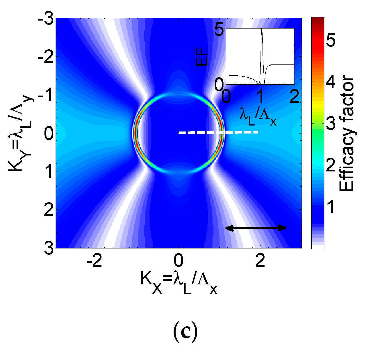
  • The second pulse, then, irradiates the attained pattern and therefore the spatial symmetry breaks; as a result, 2D modelling can no longer be used. The coupling of the electric field of the incident beam with the induced surface-scattered wave produces a nonuniform, periodic distribution of the absorbed energy. The periodic variation of the absorbed energy, in turn, leads to a periodic excited electron density distribution [9]. It is noted, however, that the computation of the amount of the absorbed energy at each position requires the evaluation of the energy deposition on a curved surface (i.e., Equation (7) for reflectivity is valid for flat profiles). Therefore, appropriate computational schemes are used to compute the absorbed energy on each point of the curved surface [9]. The calculated spatially modulated electron energy distribution is transferred to the lattice system (through the second equation of Equation (1)) and subsequently, upon phase transition fluid transport and resolidification processes, LIPSS are formed.
  • The above methodology is used to describe the formation of LIPSS for N P   2 (including a correction to the surface plasmon wavelength shift to smaller values with increasing depth of the profile following an increase in dose [13,32,39]); however, there is a resonance at which further excitation of surface plasmons stops being the driving force behind the induced surface profile and suprawavelength structures are produced. In a previous report, it was shown that if the surface profile becomes sufficiently deep (at large NP) normal thermocapillary waves which lead to regular LIPSS are not produced [8,23]. By contrast, another solution of NSE dominates, namely, hydrothermal waves that propagate between the wells of the ripples in a perpendicular direction to the laser beam polarisation [8]. Another important feature of these solutions is that, only, waves of a certain periodicity (i.e., larger than the laser wavelength) lead to stable structures upon solidification, which are orientated perpendicularly to the beam polarisation and they are termed grooves.

3. Experimental Protocol

The experiments were performed at the Ultraviolet Laser Facility operating at IESL-FORTH (Heraklion, Greece). The experimental installation, samples and irradiation conditions have been described in another of our papers [46]. In brief, (001) and (100) oriented polished surfaces of rutile TiO2 single crystals (Crystal-GmbH), maintained at room temperature, were irradiated by a hybrid distributed feedback dye laser/KrF excimer system delivering linear polarised 450 fs pulses at 248 nm at repetition rate varied of 10 Hz. The double-pulse irradiation was performed with a temporal delay between pulses varying between 0.5 and 450 ps using a Michelson-type interferometer. After appropriate spatial filtering and focusing, the laser beam on the sample was of quasi-Gaussian of size 19 μm measured at 1/e2 of the maximum intensity. The surface morphology after the irradiation was examined by Jeol Scanning Microscope JSM 7000F, which employs a Schottky type field-emission (T-FE) gun for the electron source operating at pressure 10−8 Pa, with a function for high-resolution image observation. The spatial resolution achieved was 1.2 nm at 30 kV (max accelerating voltage).

4. Discussion

To solve the Equations (1)–(9), a numerical scheme based on the use of a finite difference method is followed; the discretization of time and space has been chosen, appropriately, to satisfy the Neumann stability criterion. Von Neumann boundary conditions are considered and heat losses at the front and back surfaces of the material are negligible. The initial conditions are Tc(t = 0) = TL(t = 0) = 300 K, and Nc = 1012 cm−3 at t = 0. On the other hand, for NSE (Equation (9)), it is assumed that the velocities of the fluid at t = 0 are zero. The values of the laser beam used in the simulation are: the (peak) fluence of E p π τ p I 0 / 2 l n 2 , where I0 stands for the peak value of the intensity while R0 in Equation (5) is taken to be equal to 20 μm and τp = 450 fs. Double pulses of equal constituent pulses are used with temporal separation in the range [0 ps, 20 ps]. The ultrafast dynamics and the thermal response of the heated material are investigated to take into consideration the role of fluence, pulse separation, and crystal orientation.

4.1. Single Pulse Excitation (tdelay = 0)

Firstly, to highlight the role of crystal orientation, single pulses are used. More specifically, double pulses of zero delay (tdelay = 0) with no interference effect are considered and the ultrafast dynamics are investigated. Two sets of the equal laser pulses with Ep = 50 mJ/cm2 and Ep = 125 mJ/cm2, respectively, lead to a total pulse fluence on the solid sample of 100 mJ/cm2 and 250 mJ/cm2, respectively. The evolution of the carrier density, carrier temperature and the lattice temperatures on the surface of the material (at the centre of the Gaussian pulse where the energy absorption is maximal) are illustrated in Figure 2a–c, respectively, for the aforementioned fluences and (100) and (001) crystal orientation. Results illustrate that the maximum carrier densities are higher for (100) than for (001) which highlights the important role of the value of the optical mass. A similar monotonicity is followed by the maximum carrier temperature and simulations show that the maximum value is acquired shortly after the time the carrier density reaches the peak value which agrees with results in previous reports for other semiconductors [26,56,57,94,95]. We note there is an initial rise of the carrier temperature (Figure 2b) during the first moments of irradiation due to the significantly large heat capacity of the carrier system with respect to that of the lattice.
The main processes of energy increase from the electron system are through a (linear) one-photon and free-carrier energy absorption. After a short period, Tc rises rapidly with an increase in the pulse energy. The initial increase can be explained through the examination of the contribution of the competing mechanisms indicated by the various components in the “source term” (see an enlarged region in Figure A1 in Appendix A). Similarly, this behaviour is followed by a small decrease. At large fluences, larger amounts of carriers are produced and (given the fact that one-photon absorption and Auger recombination are the two predominant factors that alter carrier density) Auger recombination becomes significant because it varies as N c 3 . Hence, the enhanced Auger recombination [94] converts carrier ionization energy into kinetic energy that results in an increase in the carrier temperature. It is noted that Tc attains very high values and this could potentially influence the energy band-gap response. Certainly, a more rigorous approach (e.g., based on first principles [96]) should also be considered to estimate a possible Eg variation for large Tc. Nevertheless, without loss of generality, it is assumed that substantial qualitative and quantitative changes (that yields different morphological changes) do not occur if Eg is considered constant. Results indicate that differences of the maximum values of Tc and Nc for (001) and (100) at Ep = 125 mJ/cm2 are not very distinct compared to those at lower fluences due to the fact that this energy value rapidly yields maximum value of Nc close to Nv (thus, the upper value of available carriers for excitation is nearly reached). Furthermore, it is noted that although longer wavelengths and other semiconductors both impact ionization and two-photon absorption play an important role in the carrier dynamics and lattice response, for TiO2 and ΛL = 248 nm (that yield energies well above Eg) the latter processes appear to yield insignificant changes in Nc and Tc (see Appendix B). Nevertheless, for the sake of completeness and aiming to present a general theoretical framework that describes processes that also take place in other semiconductors, even at higher photon energies, a full model is considered assuming a nonzero β T P A and θ (Equation (3)).
Simulation results that represent the maximum surface lattice temperature also show that TL evolution rises faster for (001) and therefore, the crystal orientation plays an important role (Figure 2c). To avoid confusion, it is noted that the maximum value of TL (~3245 K) occurs at different depths of the irradiated material because ablation is more intense at higher fluences and therefore a larger volume is ablated. More specifically, the size of the ablated volume should be larger at higher fluences as the absorbed energy is distributed at larger depths. Nevertheless, the approach followed in the current analysis takes into account the fact that the temperatures attained are high enough to induce evaporation of the material and therefore, to avoid an overestimation of the material surface temperature in the calculations, a correction to the simulation scheme is required. Hence, becausethe boiling temperature is assumed to be the condition for evaporation, in the simulations, all points which exceed that temperature are removed. Thus, the region which is simulated at each timepoint varies dynamically and upon removal of all points with T L > T L b o i l i n g , the depth of the induced morphology increases. It is noted that the constant temperature ( T L   =   T L b o i l i n g ) in Figure 1c is due to the fact that energy relaxation between the lattice and carrier subsystems is not been reached for some picoseconds; this indicates that until the moment of equilibration between T L and T c , the carrier subsystem will continue to give energy to the lattice system which might rise above the T L b o i l i n g even if the surface points dynamically change. Hence, the surface continues to reach the boiling temperature and it evaporates leading to ablation while this elevating high temperature remains constant until relaxation processes start to become stronger. By contrast, a cutoff in the temporal decay of the carrier density or the reflectivity is not observed in the simulations. This results from the fact that the carrier density drops slowly after the end of the pulse due to an Auger recombination. Other processes that influence the variation of carrier density (see third equation in Equation (1)) such as the single photon absorption process that is dependent on the lattice temperature has ended before the lattice reaches T L b o i l i n g . Similarly, for the same Ep, the enhanced Tc for (001) yields a larger TL which, in turn, implies a larger ablation compared to the mass removal for (100).
Special attention is also required to the behaviour of the reflectivity evolution. In previous studies, it was reported that at longer wavelengths and other semiconductors (i.e., silicon), the reflectivity initially drops below the value at 300 K before it starts rising towards reaching a peak as the carrier density increases [26,66,94]. Then, as the Auger recombination becomes important and the pulse switches off, the number of carrier drops which forces the reflectivity to fall before relaxing to the initial value. A similar behaviour is also present for both orientations of rutile TiO2 (Figure 2d). Notably, although the shape of the reflectivity curves is similar for both crystal orientations, the different value of the initial reflectivity for (100) and (001) causes variation in the energy absorption. On the other hand, for the same crystal orientation, irradiation with higher fluences increases the metallisation process of the material. This leads to a rapidly enhanced carrier density followed by a larger peak value of the reflectivity of the excited material. The latter is attributed the generation of an increased number of carriers at higher fluences (Figure 2a).

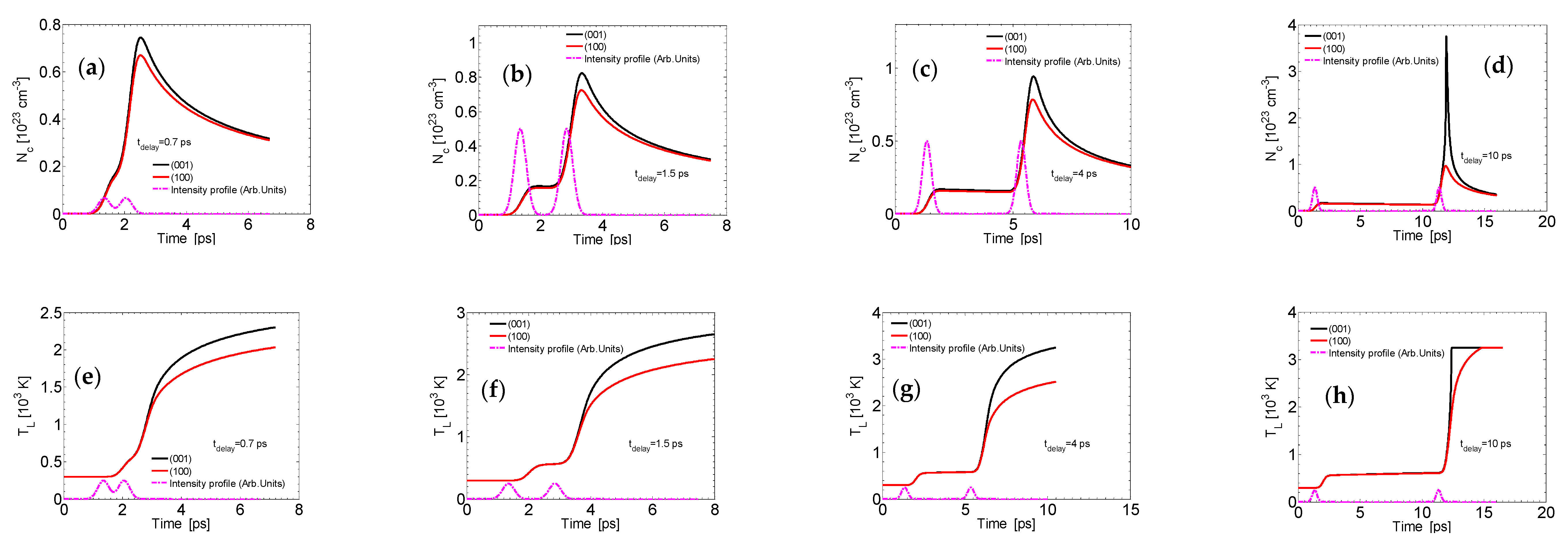
4.2. Double Pulse Excitation (tdelay ≠ 0)

To investigate the influence of irradiation with double pulses on the ultrafast dynamics Equations (1)–(7) are solved for pulse delays in the range [0,−20 ps]. In Figure 3, Figure 4 and Figure 5, the surface carrier density, reflectivity and carrier temperature evolution, respectively, are illustrated for three representative values of tdelay = 0.5 ps, 0.9 ps, and 1.5 ps for Ep = 50 mJ/cm2 and 125 mJ/cm2 and both crystal orientations. Results are shown for a temporal delay between pulses smaller than p (0.9 ps) where the two pulses overlap as well as for pulses with a larger separation (1.5 ps). According to simulations (Figure 6b,c), the maximum surface carrier density and temperature decrease gradually for short delays (tdelay < p), reaching a minimum value that remains unchanged even at longer tdelay. To explain this behaviour, it is important to note that the first of the constituent pulses leads to ablation; hence, the enhanced surface lattice temperature (~ T L b o i l i n g ) of the material yields similar α S P A (i.e., 10 6   ×   exp T L b o i l i n g / 300 cm−1) before the second pulse irradiates the material for tdelay > ~p. Figure 6a, illustrates that T L ~ T L b o i l i n g at, approximately, tdelay = 1 ps which justifies the appearance of the minimum T L at tdelay > p. This behaviour is different from the one exhibited in other laser conditions (i.e., nonablation conditions at ΛL = 800 nm) for which the second pulse leads to higher carrier densities and temperatures [36,97]. Due to the substantially larger contribution of one-photon based excitation at low wavelengths and the negligent contribution of impact ionization and two-photon ionization, the fact that α S P A remains constant at tdelay > ~p leads to unchanged values for Tc and Nc.
The above investigation is important because it also reveals both the ultrafast dynamics and temperature evolution inside the volume of the material in ablation conditions. A detailed picture of the induced thermal effects below the surface of the material will help to model the morphological changes and surface patterning procedure. However, results show that Tc, TL and Nc can provide a detailed description of the laser energy distribution and thermal effects on the affected layer of the material, exploration of dynamics through analysis of the thermal changes on the surface (in ablation conditions at Ep = 50 mJ/cm2 and 125 mJ/cm2) is hindered by the fact that the material remains at the isothermal T L   =   T L b o i l i n g for a long time and therefore, important details of the thermal effects below the surface of the material are not easily manifested. It is evident that one way to illustrate how pulse separation influences the energy absorption and thermal effects at larger depths in ablation conditions is by presenting the affected zone characteristics (i.e., temperature distribution, volume of affected zone, position of surface after ablation). By contrast, to show the impact of the laser parameters on the induced thermal effects below the ablated region (and at depths characterized by lower energy distribution), an alternative investigation is performed; more specifically, simulations are conducted assuming excitation of the material at lower fluences (i.e., that do not cause ablation; this is equivalent to exploration of dynamical effects in places where material is excited but is not removed). To emphasise on the significant role of the one-photon excitation and at conditions that do not induce ablation (i.e., T L < T L b o i l i n g ) before the second pulse irradiates the material, simulations have been performed for irradiation with Ep = 10 mJ/cm2 for tdelay = 0.7 ps, 1.5 ps, 4 ps and 10 ps (Figure 7). Interestingly, the carrier density is higher for (001) than for (100) (Figure 7a–d) unlike the behaviour for ablation conditions. This can be attributed to the almost insignificant variation of reflectivity at low fluences and the fact that energy absorption (due to lower reflectivity) is higher for (001) than for (100) at low carrier densities (Figure 4). Results for the carrier density and lattice temperature will help to understand the thermal response of the material at larger depths when high temperatures (but not equal to the boiling point are generally reached). Another interesting issue that is revealed by comparing the carrier density evolution in the two regimes (i.e., ablative and nonablative regimes) is the drop of Nc as a function of time. In contrast to the pronounced smoother gradual decrease in the carrier density value at lower fluences (part of the curve in Figure 7b–d due to the first pulse) for which the maximum attained value for Nc is low, there is a substantially steeper decrease when a substantially peak value of Nc has been reached (Figure 2a, Figure 3 and Figure 7a–d (after exposure to the second pulse)). It is noted that the smooth decrease in Nc for small carrier densities has also been reported in previous works [26,56,57,94,95].
On the other hand, given that the single photon absorption coefficient is essentially unchanged within the first of the double pulse sequence (because TL has not started to increase), any change in the carrier density is predominantly caused from the contribution of I and secondly to the Auger recombination. At low fluences (~10 mJ/cm2), no sharp increase in the carrier density is computed because it occurs at higher fluences (Figure 2a and Figure 3). By contrast, when the second constituent pulse irradiates the material, the energy of the lattice system is sufficiently high (Figure 7e–h) to lead to high levels of excitation as α S P A increases rapidly. Thus, a large number of excited carriers is produced.
Results show that for subablation conditions, the maximum TL increases as the temporal delay becomes larger. This can be attributed to the enhanced one-photon absorption ( α S P A attains large values during the first pulse, but it is about two orders higher when the second pulse irradiates the material due to its TL dependence (Figure 7e–h)) and free carrier absorption while the influence of impact ionisation appears to be minimal. According to Figure 7, the second pulse irradiates an already hot material (at increasing TL) that further increases the single photon absorption that leads to a higher carrier density which affects eventually TL through electron-phonon scattering. This is also manifested at a higher tdelay where ablation starts to occur (Figure 7h). It is noted that the tdelay value (Figure 7h) for which the temperature reaches ablation conditions, there is large jump of the carrier density to the increase in the energy absorption and production of a large number of energetic carriers. It is noted that at these fluences, reflectivity variation during the pulse is insignificant and it does not induce changes in energy absorption. To summarise, Figure 7 illustrates that in subablation conditions, an increase in the maximum values of TL occurs and due to heat diffusion and heat transfer it is more enhanced at higher depths inside the material volume as tdelay increases. These results indicate that in regions where the energy deposition is not high enough to induce material removal (at higher depths inside the material) a larger volume of the material will be affected with increasing tdelay. This conclusion is of paramount importance to interpret the distinct surface patterning at longer delays (i.e., ripples and grooves).

4.3. LIPSS Formation

The above investigation provided a detailed description of the ultrafast dynamics after the heating of rutile TiO2 of different crystal orientation with ultrashort double laser pulses.
As noted in the introductory section, a question of paramount importance is how the pulse separation and the consideration of irradiation of rutile TiO2 (001) and (100) influences the surface morphological features (i.e., types of structures and periodicities). The images in Figure 8 show the TiO2 (001) surface after irradiation with two pulses of (peak) fluence (for each pulse) Eexp = 125 mJ/cm2 and different temporal delays between laser pulses. According to results in a previous report [46], this fluence corresponds to the LSFL domain of morphological surface maps (MSM). In agreement, ripples were formed at a small delay of tdelay ≤ 4 ps (Figure 8a,b). However, at a longer delay of ~10 ps (Figure 8c), suprawavelength grooves were formed; they coarsened at even longer delay of ~30 ps (Figure 8d) and disappeared at ~60 ps, being replaced by spike-like columns (not shown).
To relate experimental data with theoretical results, it is important to estimate the dependence of the produced carrier densities with the induced surface structures as an increase in the irradiation dose (i.e., increase in NP) modifies the energy absorption and characteristics of the morphological features. For the investigation of the LIPSS formation, between the two proposed mechanisms stated in the previous section based on Sipe’s theory and the excitation of SPP, the former suffers from fundamental inconsistencies: more specifically, it is already known that one of the limitations of the efficacy factor-based theory is the neglect of the so-called ‘feedback mechanism’ which is very important to calculate the evolution of the periodicity of the induced periodic structures [34,40].
On the other hand, the SPP-based approach is used to compute the periodicities considering the produced carrier density values following the surface morphology that is induced for every pulse. In contrast to more precise electrodynamics simulations based on Finite Difference Finite Domain Schemes (FDTD) used in previous reports to correlate the induced LIPSS periodicities with increasing NP [21,24,39,84,98], an alternative and approximating methodology was employed, in this work, to relate the SP wavelength with the produced maximum depth of the corrugated profile [78,79] (i.e., which is directly linked with NP). The methodology is based on the spatial distribution of the electric field on a corrugated surface of particular periodicity and height and how continuity of the electromagnetic fields influences the features of the associated SPP. Results for SPP wavelength as a function of NP are illustrated in Figure 9 for Ep = 125 mJ/cm2 for (100) and (001) TiO2, respectively (tdelay = 4 ps). As mentioned in the previous section, the decrease in SPP wavelength with the increase in the irradiation dose NP is related to the expected shift of SPP wavelength to smaller values as the profile becomes deeper [21,78]. Furthermore, according to Figure 7a–h, the larger carrier densities (and thermal response) produced for the orientation (001) lead to a more rapidly attained deeper profile with respect to that for (100). Hence, the curve that shows the decrease in the ripple periodicity as a function of NP should be steeper for (001) while SPP wavelengths also are expected to expand to a larger range of values (Figure 9). Furthermore, simulation results predict a substantially smaller SPP wavelength for (001) orientation which should be also projected on the periodicity of the induced ripples.
Apart from the comparison of the LIPSS periodicities following irradiation with the same fluence, pulse separation (tdelay = 4 ps), and NP, it is also very important to evaluate potential morphological variations for different pulse separation. In Figure 10, simulations and experimental results are shown after a double pulse of Ep = 125 mJ/cm2 irradiated (001) TiO2 for two delays, tdelay = 4 ps and tdelay = 10 ps. An interesting point regarding the two values of the pulse separation is that they are situated before and past an optimum pulse separation value (tdelay~6 ps) for which the depth is critical to lead to a transition of structures from ripples (i.e., subwavelength structures oriented perpendicularly to the laser polarization direction) to grooves (i.e., suprawavelength structures that are aligned with laser polarization direction); therefore it is important to evaluate the impact of small and large pulse separation. Due to the fact that for a smaller pulse separation (tdelay = 4 ps), damage related temperatures will be developed into smaller regions, a shallower profile will be produced compared to that for tdelay = 10 ps. Hence, the condition for promoting the production of grooves will be satisfied more easily at longer delays. Simulation results show rippled structures (Figure 10a) for NP = 80 for the above conditions at tdelay = 4 ps of periodicity ~220 nm and grooves (Figure 10b) for NP = 80 at tdelay = 10 ps of periodicity ~1.8 μm. Experimental results on (001) TiO2 rutile surface that validate the simulations are illustrated in Figure 8b,c, which show the production of ripples and grooves, respectively, for NP = 100. Interestingly, irradiation of (100) rutile TiO2 surface does not lead to the formation of grooves [46]. Instead of grooves, a featureless flat area replaces the ripples when the delay between laser pluses increases (see Appendix C). The formation of this unusual structure is not yet explained by simulations. This emphasises that crystalline orientation of the irradiated surfaces is a key parameter in the formation processes of suprawavelength periodic structures under femtosecond laser irradiation.
The multiscale model used in this work described the physical processes that account for the formation of LSFL on TiO2 while a transition from ripples to grooves was also derived. It is evident that more accurate conclusions will be drawn if more appropriately developed experimental (for example time-resolved) protocols are also introduced to evaluate ultrafast dynamics and relevant parameter valuessuch as electron-electron and electron-hole scattering frequencies, electron-phonon relaxation times, and reflectivity changes. It is noted that although the theoretical predictions appear to agree with the evolution of the surface structures, simulation results manifested a significant ablation that takes place for the fluence values used in the experiment which to some extent deviates from experimental observations. This can also be attributed to the choice of various parameters such as the electron effective mass that affects the dielectric constant and eventually the optical properties of the material and energy absorption; this is a critical issue to both the induced carrier density and thermal response of the material. Values for m o p t * used in the current work and at low wavelengths might need to be revised appropriately through a more rigorous theoretical approach and suitable experimental protocols. Similarly, in extreme laser conditions that induce severe ablation, it is very important to estimate more accurately the role of evaporation and employ more advanced theoretical schemes such as FDTD algorithms to evaluate electrodynamical effects that are related to the underlying mechanisms of surface modification [24]. Nevertheless, the predominant aim of the study focused on the exploration of the underlying physical mechanisms that correlate laser parameters with the material’s crystal orientation and the induced ultrafast dynamics and produced surface patterns. The qualitative and quantitative results presented in the current investigation were aimed to provide a first insight into the patterning techniques of rutile TiO2 with femtosecond pulses in ablation conditions and highlight the significant role of the material characteristics of the material related to the crystal orientation in the response of the solid. The detailed analysis emphasized the role of the different direction dependence of the electron effective masses for the two crystal orientations as the distinct two cases lead to different excitation processes, energy absorption and anisotropic laser surface patterning.

5. Conclusions

A detailed theoretical framework was presented that describes both the ultrafast dynamics and surface modification physical mechanisms after the heating of rutile TiO2 of different crystal orientations with ultrashort double laser pulses in ablation conditions. Results manifest that the crystal orientations and interpulse delays play an important role in the onset of surface pattern formation because they influence both the carrier dynamics and thermal response of the irradiated structure. Simulations showed that although both the maximum carrier temperature and density drop with increasing pulse separation, these parameters reach a minimum value at about tdelay > p after which no variation occurs. Interestingly, irradiation of TiO2 with (100) orientation lead to higher Tc and Nc values than for (001) which are well explained by the underlying physical processes and the excitation conditions. To illustrate the response of the material deeper in the surface of the irradiated solid, simulations indicated an increase in the maximum values of TL due to heat diffusion and heat transfer that is more enhanced at higher depths inside the material volume as tdelay increases. These results are very important because they are also associated with the induced surface patterning. Furthermore, surface modification is greatly affected by the pulse separation and both simulation results and experimental observations explain the occurrence of grooves on (001) compared to the formation of subwavelength structures at smaller delays. For values of the pulse separation past an threshold value (~ 6 ps), the depth of the surface pattern allow the formation of grooves instead of ripples, which indicates that the modulation of the frequencies of the induced LIPSS on the surfaces of solids can be tailored by a control of tdelay and the number of pulses. Furthermore, simulation results indicate that the crystal orientation influences the periodicity of the LSFL structures, leading to patterns of lower periodicity for (001) TiO2.
The approach is aimed to provide a systematic laser-based processing strategy of materials and tailor the morphology of an irradiated surface according to the demand of exciting applications ranging from biomedical engineering to photovoltaics and nanoelectronics.

Author Contributions

G.D.T., L.M., A.K. presented the idea, G.D.T. conducted the theoretical work and modelling of the physical processes while L.M. and A.K. conducted the experiments. All the authors discussed the results and defined the content of the manuscript. G.D.T. wrote the original draft of the manuscript, which was amended and finalised with the contribution of all the authors. All authors have read and agreed to the published version of the manuscript.

Funding

This research was funded by the following funding schemes: (1) HELLAS-CH project (MIS 5002735), implemented under the “Action for Strengthening Research and Innovation Infrastructures,” (2) the Operational Programme “Competitiveness, Entrepreneurship and Innovation” and co-financed by Greece and the EU (European Regional Development Fund), Nanoscience Foundries and Fine Analysis (NFFA)–Europe H2020-INFRAIA-2014-2015 (Grant Agreement No. 654360), (3) COST Action TUMIEE (supported by COST-European Cooperation in Science and Technology), (4) MouldTeX project-H2020-EU.2.1.5.1 (Grant agreement No 768705), (5) Laserlab-Europe IV project, transnational access project: ulf-forth-2258 (Grant-Agreement 654148)

Conflicts of Interest

The authors declare that they have no known competing financial interests or personal relationships that could have appeared to influence the work reported in this paper.

Appendix A

Figure A1 illustrates an enlarged picture of the evolution of carrier temperature at smaller timepoints in order to highlight the increase in Tc. It is evident that the carrier energy increases even when the laser energy is very low and, in principle, the linear processes such as single photon absorption and free carrier absorption account for this increase. As shown in Figure A1, the carrier temperature attains the maximum value shortly after the laser pulse reaches its maximum.
Figure A1. Evolution of values of carrier for Ep = 50 mJ/cm2 and 125 mJ/cm2 for (001) and (100) crystal orientation at x = y = 0 and on the surface of the material.
Applsci 10 08811 g0a1

Appendix B

To emphasise the insignificant influence of theimpact ionisation and two-photon absorption assisted excitation processes, the carrier density and temperature are illustrated (Figure A1). Results indicate that excitation is not affected from the two processes. By contrast, single photon absorption dominates the excitation process. Additionally, as explained also in previous studies [26,56,57,94,95], an initial rise and small drop is exhibited in Tc as a result of the single photon absorption and Auger recombination.
Figure A2. Simulation results of maximum carrier density (a) and carrier temperature (b) for tdelay = 0 ps, Ep = 50 mJ/cm2 for (100) TiO2.
Applsci 10 08811 g0a2

Appendix C

Figure A3. SEM images of surface structures on (100) rutile TiO2 obtained after laser irradiation (248 nm, 450 ps, NP = 100) with total measured fluence of 300 mJ/cm² and delay between pulses of 4 ps (a) and 10 ps (b). The double-headed arrow indicates the direction of laser polarization.
Applsci 10 08811 g0a3

References

  1. Vorobyev, A.Y.; Guo, C. Direct femtosecond laser surface nano/microstructuring and its applications. Laser Photon. Rev. 2013, 7, 385–407. [Google Scholar] [CrossRef]
  2. Zorba, V.; Persano, L.; Pisignano, D.; Athanassiou, A.; Stratakis, E.; Cingolani, R.; Tzanetakis, P.; Fotakis, C. Making silicon hydrophobic: Wettability control by two-lengthscale simultaneous patterning with femtosecond laser irradiation. Nanotechnology 2006, 17, 3234–3238. [Google Scholar] [CrossRef]
  3. Zorba, V.; Stratakis, E.; Barberoglou, M.; Spanakis, E.; Tzanetakis, P.; Anastasiadis, S.H.; Fotakis, C. Biomimetic Artificial Surfaces Quantitatively Reproduce the Water Repellency of a Lotus Leaf. Adv. Mater. 2008, 20, 4049–4054. [Google Scholar] [CrossRef]
  4. Zimmer, K. Laser Processing and Chemistry. Z. Phys. Chem. 1999, 208, 291–292. [Google Scholar] [CrossRef]
  5. Diels, J.-C.; Rudolph, W. Ultrashort Laser Pulse Phenomena: Fundamentals, Techniques, and Applications on a Femtosecond Time Scale, 2nd ed.; Elsevier: Amsterdam, The Netherlands, 2006. [Google Scholar]
  6. Papadopoulou, E.L.; Samara, A.; Barberoglou, M.; Manousaki, A.; Pagakis, S.N.; Anastasiadou, E.; Fotakis, C.; Stratakis, E. Silicon Scaffolds Promoting Three-Dimensional Neuronal Web of Cytoplasmic Processes. Tissue Eng. Part C Methods 2010, 16, 497–502. [Google Scholar] [CrossRef]
  7. Wang, Z.B.; Hong, M.H.; Lu, Y.F.; Wu, D.J.; Lan, B.; Chong, T.C. Femtosecond laser ablation of polytetrafluoroethylene (Teflon) in ambient air. J. Appl. Phys. 2003, 93, 6375–6380. [Google Scholar] [CrossRef]
  8. Böhme, R.; Pissadakis, S.; Ruthe, D.; Zimmer, K. Laser backside etching of fused silica with ultra-short pulses. Appl. Phys. A 2006, 85, 75–78. [Google Scholar] [CrossRef]
  9. Petrović, S.M.; Gakovic, B.M.; Peruško, D.; Stratakis, E.; Bogdanovicradovic, I.; Cekada, M.; Fotakis, C.; Jelenkovic, B.M. Femtosecond laser-induced periodic surface structure on the Ti-based nanolayered thin films. J. Appl. Phys. 2013, 114, 233108. [Google Scholar] [CrossRef]
  10. Stratakis, E.; Bonse, J.; Heitz, J.; Siegel, J.; Tsibidis, G.; Skoulas, E.; Papadopoulos, A.; Mimidis, A.; Joel, A.-C.; Comanns, P.; et al. Laser engineering of biomimetic surfaces. Mater. Sci. Eng. R Rep. 2020, 141, 100562. [Google Scholar] [CrossRef]
  11. Stratakis, E.; Ranella, A.; Fotakis, C. Biomimetic micro/nanostructured functional surfaces for microfluidic and tissue engineering applications. Biomicrofluidics 2011, 5, 013411. [Google Scholar] [CrossRef] [Green Version]
  12. Bonse, J.; Koter, R.; Hartelt, M.; Spaltmann, D.; Pentzien, S.; Höhm, S.; Rosenfeld, A.; Kruger, J. Femtosecond laser-induced periodic surface structures on steel and titanium alloy for tribological applications. Appl. Phys. A 2014, 117, 103–110. [Google Scholar] [CrossRef]
  13. Lu, Y.; Hua, M.; Liu, Z. The Biomimetic Shark Skin Optimization Design Method for Improving Lubrication Effect of Engineering Surface. J. Tribol. 2014, 136, 031703–3170313. [Google Scholar] [CrossRef]
  14. Wang, Z.; Li, Y.-B.; Bai, F.; Wang, C.-W.; Zhao, Q.-Z. Angle-dependent lubricated tribological properties of stainless steel by femtosecond laser surface texturing. Opt. Laser Technol. 2016, 81, 60–66. [Google Scholar] [CrossRef]
  15. Simitzi, C.; Efstathopoulos, P.; Kourgiantaki, A.; Ranella, A.; Charalampopoulos, I.; Fotakis, C.; Athanassakis, I.; Stratakis, E.; Gravanis, A. Laser fabricated discontinuous anisotropic microconical substrates as a new model scaffold to control the directionality of neuronal network outgrowth. Biomaterials 2015, 67, 115–128. [Google Scholar] [CrossRef]
  16. Jiang, H.-B.; Zhang, Y.-L.; Liu, Y.; Fu, X.; Li, Y.; Liu, Y.-Q.; Li, C.-H.; Sun, H.-B. Bioinspired few-layer graphene prepared by chemical vapor deposition on femtosecond laser-structured Cu foil. Laser Photon. Rev. 2016, 10, 441–450. [Google Scholar] [CrossRef]
  17. Papadopoulos, A.; Skoulas, E.; Mimidis, A.; Perrakis, G.; Kenanakis, G.; Tsibidis, G.D.; Stratakis, E. Biomimetic Omnidirectional Antireflective Glass via Direct Ultrafast Laser Nanostructuring. Adv. Mater. 2019, 31, e1901123. [Google Scholar] [CrossRef]
  18. Bonse, J.; Hohm, S.; Kirner, S.V.; Rosenfeld, A.; Kruger, J. Laser-Induced Periodic Surface Structures—A Scientific Evergreen. IEEE J. Sel. Top. Quantum Electron. 2017, 23, 1–15. [Google Scholar] [CrossRef]
  19. Skoulas, E.; Manousaki, A.; Fotakis, C.; Stratakis, E. Biomimetic surface structuring using cylindrical vector femtosecond laser beams. Sci. Rep. 2017, 7, 45114. [Google Scholar] [CrossRef] [Green Version]
  20. Nivas, J.J.J.; He, S.; Rubano, A.; Vecchione, A.; Paparo, D.; Marrucci, L.; Bruzzese, R.; Amoruso, S. Direct Femtosecond Laser Surface Structuring with Optical Vortex Beams Generated by a q-plate. Sci. Rep. 2015, 5, 17929. [Google Scholar] [CrossRef] [Green Version]
  21. Huang, M.; Zhao, F.; Cheng, Y.; Xu, N.; Xu, Z. Origin of Laser-Induced Near-Subwavelength Ripples: Interference between Surface Plasmons and Incident Laser. ACS Nano 2009, 3, 4062–4070. [Google Scholar] [CrossRef]
  22. Tsibidis, G.D.; Barberoglou, M.; Loukakos, P.A.; Stratakis, E.; Fotakis, C. Dynamics of ripple formation on silicon surfaces by ultrashort laser pulses in subablation conditions. Phys. Rev. B 2012, 86, 115316. [Google Scholar] [CrossRef] [Green Version]
  23. Bonse, J.; Kruger, J.; Höhm, S.; Rosenfeld, A. Femtosecond laser-induced periodic surface structures. J. Laser Appl. 2012, 24, 042006. [Google Scholar] [CrossRef]
  24. Rudenko, A.; Colombier, J.-P.; Höhm, S.; Rosenfeld, A.; Krüger, J.; Bonse, J.; Itina, T.E. Spontaneous periodic ordering on the surface and in the bulk of dielectrics irradiated by ultrafast laser: A shared electromagnetic origin. Sci. Rep. 2017, 7, 12306. [Google Scholar] [CrossRef]
  25. Tsibidis, G.D.; Fotakis, C.; Stratakis, E. From ripples to spikes: A hydrodynamical mechanism to interpret femtosecond laser-induced self-assembled structures. Phys. Rev. B 2015, 92, 041405. [Google Scholar] [CrossRef] [Green Version]
  26. Van Driel, H.M. Kinetics of high-density plasmas generated in Si by 1.06- and 0.53-μmpicosecond laser pulses. Phys. Rev. B 1987, 35, 8166–8176. [Google Scholar] [CrossRef]
  27. Sundaram, S.K.; Mazur, E. Inducing and probing non-thermal transitions in semiconductors using femtosecond laser pulses. Nat. Mater. 2002, 1, 217–224. [Google Scholar] [CrossRef]
  28. Knoesel, E.; Hotzel, A.; Wolf, M. Ultrafast dynamics of hot electrons and holes in copper: Excitation, energy relaxation, and transport effects. Phys. Rev. B 1998, 57, 12812–12824. [Google Scholar] [CrossRef] [Green Version]
  29. Derrien, T.J.Y.; Krüger, J.; Itina, T.E.; Höhm, S.; Rosenfeld, A.; Bonse, J. Rippled area formed by surface plasmon polaritons upon femtosecond laser double-pulse irradiation of silicon: The role of carrier generation and relaxation processes. Appl. Phys. A 2013, 117, 77–81. [Google Scholar] [CrossRef] [Green Version]
  30. Derrien, T.J.-Y.; Itina, T.E.; Torres, R.; Sarnet, T.; Sentis, M. Possible surface plasmon polariton excitation under femtosecond laser irradiation of silicon. J. Appl. Phys. 2013, 114, 083104. [Google Scholar] [CrossRef]
  31. Bonse, J.; Munz, M.; Sturm, H. Structure formation on the surface of indium phosphide irradiated by femtosecond laser pulses. J. Appl. Phys. 2005, 97, 013538. [Google Scholar] [CrossRef] [Green Version]
  32. Van Driel, H.; Young, J.F.; Sipe, J. Laser Induced Periodic Surface Structure. MRS Proc. 1982, 13, 1141–1154. [Google Scholar] [CrossRef]
  33. Tsibidis, G.D.; Skoulas, E.; Papadopoulos, A.; Stratakis, E. Convection roll-driven generation of supra-wavelength periodic surface structures on dielectrics upon irradiation with femtosecond pulsed lasers. Phys. Rev. B 2016, 94, 081305. [Google Scholar] [CrossRef] [Green Version]
  34. Bonse, J.; Rosenfeld, A.; Krueger, J. On the role of surface plasmon polaritons in the formation of laser-induced periodic surface structures upon irradiation of silicon by femtosecond-laser pulses. J. Appl. Phys. 2009, 106, 104910. [Google Scholar] [CrossRef]
  35. Cheng, K.; Liu, J.; Cao, K.; Chen, L.; Zhang, Y.; Jiang, Q.; Feng, D.; Zhang, S.; Su, Z.; Jia, T. Ultrafast dynamics of single-pulse femtosecond laser-induced periodic ripples on the surface of gold films. Phys. Rev. B 2018, 98, 184106. [Google Scholar] [CrossRef]
  36. Barberoglou, M.; Tsibidis, G.D.; Gray, D.; Magoulakis, E.; Fotakis, C.; Stratakis, E.; Loukakos, P.A. The influence of ultra-fast temporal energy regulation on the morphology of Si surfaces through femtosecond double pulse laser irradiation. Appl. Phys. A 2013, 113, 273–283. [Google Scholar] [CrossRef]
  37. Tsibidis, G.D.; Stratakis, E.; Loukakos, P.A.; Fotakis, C. Controlled ultrashort-pulse laser-induced ripple formation on semiconductors. Appl. Phys. A 2014, 114, 57–68. [Google Scholar] [CrossRef]
  38. Varlamova, O.; Costache, F.; Reif, J.; Bestehorn, M. Self-organized pattern formation upon femtosecond laser ablation by circularly polarized light. Appl. Surf. Sci. 2006, 252, 4702–4706. [Google Scholar] [CrossRef]
  39. Rudenko, A.; Colombier, J.-P.; Itina, T.E. From random inhomogeneities to periodic nanostructures induced in bulk silica by ultrashort laser. Phys. Rev. B 2016, 93, 075427. [Google Scholar] [CrossRef] [Green Version]
  40. Sipe, J.E.; Young, J.F.; Preston, J.S.; Van Driel, H.M. Laser-induced periodic surface structure. I. Theory. Phys.Rev.B. 1983, 27, 1141–1154. [Google Scholar] [CrossRef]
  41. Tsibidis, G.D. Ultrafast dynamics of non-equilibrium electrons and strain generation under femtosecond laser irradiation of Nickel. Appl. Phys. A 2018, 124, 311. [Google Scholar] [CrossRef] [Green Version]
  42. Tsibidis, G.D. The influence of dynamical change of optical properties on the thermomechanical response and damage threshold of noble metals under femtosecond laser irradiation. J. Appl. Phys. 2018, 123, 085903. [Google Scholar] [CrossRef] [Green Version]
  43. Chimier, B.; Utéza, O.; Sanner, N.; Sentis, M.; Itina, T.E.; Lassonde, P.; Légaré, F.; Vidal, F.; Kieffer, J.C. Damage and ablation thresholds of fused-silica in femtosecond regime. Phys. Rev. B 2011, 84, 094104. [Google Scholar] [CrossRef] [Green Version]
  44. Nathala, C.S.R.; Ajami, A.; Husinsky, W.; Farooq, B.; Kudryashov, S.I.; Daskalova, A.; Bliznakova, I.; Assion, A. Ultrashort laser pulse ablation of copper, silicon and gelatin: Effect of the pulse duration on the ablation thresholds and the incubation coefficients. Appl. Phys. A 2016, 122, 1–8. [Google Scholar] [CrossRef] [Green Version]
  45. Ionin, A.A.; Kudryashov, S.; Makarov, S.V.; Seleznev, L.V.; Sinitsyn, D.V. Electron dynamics and prompt ablation of aluminum surface excited by intense femtosecond laser pulse. Appl. Phys. A 2014, 117, 1757–1763. [Google Scholar] [CrossRef]
  46. Museur, L.; Tsibidis, G.D.; Manousaki, A.; Anglos, D.; Kanaev, A. Surface structuring of rutile TiO2(100) and (001) single crystals with femtosecond pulsed laser irradiation. J. Opt. Soc. Am. B 2018, 35, 2600–2607. [Google Scholar] [CrossRef]
  47. Breckenridge, R.G.; Hosler, W.R. Electrical Properties of Titanium Dioxide Semiconductors. Phys. Rev. 1953, 91, 793–802. [Google Scholar] [CrossRef]
  48. Ekuma, C.E.; Bagayoko, D. Ab-initio Electronic and Structural Properties of Rutile Titanium Dioxide. Jpn. J. Appl. Phys. 2011, 50, 101103. [Google Scholar] [CrossRef] [Green Version]
  49. Xiong, Q.-L.; Li, Z.; Kitamura, T. Effect of Crystal Orientation on Femtosecond Laser-Induced Thermomechanical Responses and Spallation Behaviors of Copper Films. Sci. Rep. 2017, 7, 1–14. [Google Scholar] [CrossRef] [Green Version]
  50. Hendry, E.; Koeberg, M.; Pijpers, J.; Bonn, M. Reduction of carrier mobility in semiconductors caused by charge-charge interactions. Phys. Rev. B 2007, 75. [Google Scholar] [CrossRef] [Green Version]
  51. Dou, M.; Persson, C. Comparative study of rutile and anatase SnO2 and TiO2: Band-edge structures, dielectric functions, and polaron effects. J. Appl. Phys. 2013, 113, 083703. [Google Scholar] [CrossRef]
  52. Kang, W.; Hybertsen, M.S. Quasiparticle and optical properties of rutile and anatase TiO2. Phys. Rev. B 2010, 82, 085203. [Google Scholar] [CrossRef] [Green Version]
  53. Yagi, E.; Hasiguti, R.R.; Aono, M. Electronic conduction above 4 K of slightly reduced oxygen-deficient rutile TiO2-x. Phys. Rev. B 1996, 54, 7945–7956. [Google Scholar] [CrossRef]
  54. Zajac, V.; Němec, H.; Kužel, P. Picosecond charge transport in rutile at high carrier densities studied by transient terahertz spectroscopy. Phys. Rev. B 2016, 94, 115206. [Google Scholar] [CrossRef] [Green Version]
  55. Itina, T.E.; Shcheblanov, N. Electronic excitation in femtosecond laser interactions with wide-band-gap materials. Appl. Phys. A 2010, 98, 769–775. [Google Scholar] [CrossRef]
  56. Chen, J.; Tzou, D.; Beraun, J. Numerical investigation of ultrashort laser damage in semiconductors. Int. J. Heat Mass Transf. 2005, 48, 501–509. [Google Scholar] [CrossRef]
  57. Rämer, A.; Osmani, O.; Rethfeld, B. Laser damage in silicon: Energy absorption, relaxation, and transport. J. Appl. Phys. 2014, 116, 053508. [Google Scholar] [CrossRef] [Green Version]
  58. Anisimov, S.I.; Kapeliovich, B.L.; Perel’man, T.L. Electron-emission from surface of metals induced by ultrashort laser pulses. J. Exp. Theor. Phys. 1974, 66, 776. [Google Scholar]
  59. De Ligny, D.; Richet, P.; Westrum, E.F., Jr.; Roux, J. Heat capacity and entropy of rutile (TiO2) and nepheline (NaAlSiO4). Phys. Chem. Miner. 2002, 29, 267–272. [Google Scholar] [CrossRef] [Green Version]
  60. Data. Available online: https://www.azom.com/properties.aspx?ArticleID=1179 (accessed on 4 February 2020).
  61. Jellison, G.E. Optical absorption of silicon between 1.6 and 4.7 eV at elevated temperatures. Appl. Phys. Lett. 1982, 41, 180. [Google Scholar] [CrossRef]
  62. Penzkofer, A.; Falkenstein, W. Direct determination of the intensity of picosecond light pulses by two-photon absorption. Opt. Commun. 1976, 17, 1–5. [Google Scholar] [CrossRef] [Green Version]
  63. Yamada, Y.; Kanemitsu, Y. Blue photoluminescence of highly photoexcited rutileTiO2: Nearly degenerate conduction-band effects. Phy. Rev. B 2010, 82, 113103. [Google Scholar] [CrossRef] [Green Version]
  64. Wu, A.Q.; Chowdhury, I.H.; Xu, X. Femtosecond laser absorption in fused silica: Numerical and experimental investigation. Phys. Rev. B 2005, 72, 085128. [Google Scholar] [CrossRef] [Green Version]
  65. Lee, S.H.; Lee, J.S.; Park, S.; Choi, Y.K. Numerical analysis on heat transfer characteristics of a silicon film irradiated by pico-to femtosecond pulse lasers. Numer. Heat Transf. Part A-Appl. 2003, 44, 833–850. [Google Scholar] [CrossRef]
  66. Sokolowski-Tinten, K.; Von Der Linde, D. Generation of dense electron-hole plasmas in silicon. Phys. Rev. B 2000, 61, 2643–2650. [Google Scholar] [CrossRef] [Green Version]
  67. Palik, E.D.; Ghosh, G. Handbook of Optical Constants of Solids; Academic Press: San Diego, CA, USA, 1998. [Google Scholar]
  68. Cardona, M.; Harbeke, G. Optical Properties and Band Structure of Wurtzite-Type Crystals and Rutile. Phys. Rev. 1965, 137, A1467–A1476. [Google Scholar] [CrossRef]
  69. Vos, K.; Krusemeyer, H.J. Reflectance and Electroreflectance of Tio2 Single-Crystals. 1. Optical-Spectra. J. Phys. C Solid State 1977, 10, 3893–3915. [Google Scholar] [CrossRef]
  70. Glassford, K.M.; Chelikowsky, J.R. Optical properties of titanium dioxide in the rutile structure. Phys. Rev. B 1992, 45, 3874–3877. [Google Scholar] [CrossRef]
  71. Tiwald, T.; Schubert, M. Measurement of Rutile TiO2 Dielectric Tensor from 0.148 to 33 um Using Generalized Ellipsometry; SPIE: Bellingham, WA, USA, 2000. [Google Scholar]
  72. Landmann, M.; Rauls, E.; Schmidt, W.G. The electronic structure and optical response of rutile, anatase and brookite TiO2. J. Phys. Condens. Matter 2012, 24, 195503. [Google Scholar] [CrossRef] [Green Version]
  73. Tsibidis, G.D.; Skoulas, E.; Stratakis, E. Ripple formation on nickel irradiated with radially polarized femtosecond beams. Opt. Lett. 2015, 40, 5172–5175. [Google Scholar] [CrossRef] [Green Version]
  74. Bonse, J. Quo Vadis LIPSS?—Recent and Future Trends on Laser-Induced Periodic Surface Structures. Nanomaterials 2020, 10, 1950. [Google Scholar] [CrossRef]
  75. Guosheng, Z.; Fauchet, P.M.; Siegman, A.E. Growth of spontaneous periodic surface structures on solids during laser illumination. Phys. Rev. B 1982, 26, 5366–5381. [Google Scholar] [CrossRef]
  76. Tsibidis, G.D.; Stratakis, E.; Aifantis, K.E. Thermoplastic deformation of silicon surfaces induced by ultrashort pulsed lasers in submelting conditions (Volume 111, 053502, 2012). J. Appl. Phys. 2012, 112, 089901. [Google Scholar] [CrossRef] [Green Version]
  77. Papadopoulos, A.; Skoulas, E.; Tsibidis, G.D.; Stratakis, E. Formation of periodic surface structures on dielectrics after irradiation with laser beams of spatially variant polarisation: A comparative study. Appl. Phys. A 2018, 124, 146. [Google Scholar] [CrossRef] [Green Version]
  78. Tsibidis, G.D.; Stratakis, E. Ripple formation on silver after irradiation with radially polarised ultrashort-pulsed lasers. J. Appl. Phys. 2017, 121, 163106. [Google Scholar] [CrossRef]
  79. Tsibidis, G.D.; Mimidis, A.; Skoulas, E.; Kirner, S.V.; Krüger, J.; Bonse, J.; Stratakis, E. Modelling periodic structure formation on 100Cr6 steel after irradiation with femtosecond-pulsed laser beams. Appl. Phys. A 2018, 124, 27. [Google Scholar] [CrossRef] [Green Version]
  80. Birnbaum, M. Semiconductor Surface Damage Produced by Ruby Lasers. J. Appl. Phys. 1965, 36, 3688–3689. [Google Scholar] [CrossRef]
  81. Zuhlke, C.A.; Tsibidis, G.D.; Anderson, T.; Stratakis, E.; Gogos, G.; Alexander, D.R. Investigation of femtosecond laser induced ripple formation on copper for varying incident angle. AIP Adv. 2018, 8, 015212. [Google Scholar] [CrossRef] [Green Version]
  82. Raether, P.D.H. Surface Plasmons on Smooth and Rough Surfaces and on Gratings; Springer Science and Business Media LLC.: Berlin/Heidelberg, Germany, 1988. [Google Scholar]
  83. Tsibidis, G.D.; Stratakis, E. Ionisation processes and laser induced periodic surface structures in dielectrics with mid-infrared femtosecond laser pulses. Sci. Rep. 2020, 10, 1–13. [Google Scholar] [CrossRef]
  84. Fuentes-Edfuf, Y.; Sánchez-Gil, J.A.; Garcia-Pardo, M.; Serna, R.; Tsibidis, G.D.; Giannini, V.; Solis, J.; Siegel, J. Tuning the period of femtosecond laser induced surface structures in steel: From angled incidence to quill writing. Appl. Surf. Sci. 2019, 493, 948–955. [Google Scholar] [CrossRef]
  85. Höhm, S.; Rosenfeld, A.; Kruger, J.; Bonse, J. Femtosecond laser-induced periodic surface structures on silica. J. Appl. Phys. 2012, 112, 014901. [Google Scholar] [CrossRef]
  86. Pierre, P.D.S.S. A Note on the Melting Point of Titanium Dioxide. J. Am. Ceram. Soc. 1952, 35, 188. [Google Scholar] [CrossRef]
  87. Burakov, I.; Bulgakova, N.M.; Stoian, R.; Rosenfeld, A.; Hertel, I. Theoretical investigations of material modification using temporally shaped femtosecond laser pulses. Appl. Phys. A 2005, 81, 1639–1645. [Google Scholar] [CrossRef]
  88. Kelly, R.; Miotello, A. Comments on explosive mechanisms of laser sputtering. Appl. Surf. Sci. 1996, 96–98, 205–215. [Google Scholar] [CrossRef]
  89. Kerley, G.I.; Services, G.I.; Kerley, T. Equations of State for Titanium and Ti6A14V Alloy; Sandia National Laboratories: Albuquerque, NM, USA, 2003. [Google Scholar] [CrossRef] [Green Version]
  90. Alderman, O.L.G.; Skinner, L.B.; Benmore, C.J.; Tamalonis, A.; Weber, J. Structure of molten titanium dioxide. Phys. Rev. B 2014, 90, 094204. [Google Scholar] [CrossRef] [Green Version]
  91. Zhou, K.; Wang, H.P.; Chang, J.; Wei, B. Experimental study of surface tension, specific heat and thermal diffusivity of liquid and solid titanium. Chem. Phys. Lett. 2015, 639, 105–108. [Google Scholar] [CrossRef]
  92. Fletcher, C.A.J.; Srinivas, K. Computational Techniques for Fluid Dynamics, 2nd ed.; Springer: Berlin/Heidelberg, Germany; New York, NY, USA, 1991. [Google Scholar]
  93. Wang, Y.; Tsai, H.L. Impingement of filler droplets and weld pool dynamics during gas metal are welding process. Int. J. Heat Mass Transf. 2001, 44, 2067–2080. [Google Scholar] [CrossRef]
  94. Margiolakis, A.; Tsibidis, G.D.; Dani, K.M.; Tsironis, G.P. Ultrafast dynamics and sub-wavelength periodic structure formation following irradiation of GaAs with femtosecond laser pulses. Phys. Rev. B 2018, 98, 224103. [Google Scholar] [CrossRef] [Green Version]
  95. Petrakakis, E.; Tsibidis, G.D.; Stratakis, E. Modelling of the ultrafast dynamics and surface plasmon properties of silicon upon irradiation with mid-IR femtosecond laser pulses. Phys. Rev. B 2019, 99, 195201. [Google Scholar] [CrossRef] [Green Version]
  96. Tsibidis, G.D.; Mouchliadis, L.; Pedio, M.; Stratakis, E. Modeling ultrafast out-of-equilibrium carrier dynamics and relaxation processes upon irradiation of hexagonal silicon carbide with femtosecond laser pulses. Phys. Rev. B 2020, 101, 075207. [Google Scholar] [CrossRef] [Green Version]
  97. Derrien, T.J.-Y.; Krüger, J.; Itina, T.E.; Höhm, S.; Rosenfeld, A.; Bonse, J. Rippled area formed by surface plasmon polaritons upon femtosecond laser double-pulse irradiation of silicon. Opt. Express 2013, 21, 29643–29655. [Google Scholar] [CrossRef] [Green Version]
  98. Skolski, J.Z.P.; Römer, G.R.B.E.; Obona, J.V.; Ocelik, V.; Veld, A.J.H.I.; de Hosson, J.T.M. Laser-induced periodic surface structures: Fingerprints of light localization. Phys. Rev. B 2012, 85, 075320. [Google Scholar] [CrossRef] [Green Version]
Figure 1. (a) Surface plasmon wavelength as a function of the excited carrier densities for (001) and (100) crystal orientation. Prediction of structure periodicity based on Sipe’s theory for (b) 44 × 1022 cm−3 (100) and (c) 27 × 1022 cm−3 (001). Inset shows the profile of the efficacy factor along Kx (white dashed line). The black double headed arrow indicates the direction of the polarisation vector.
Applsci 10 08811 g001aApplsci 10 08811 g001b
Figure 2. Evolution of values of carrier density (a), carrier temperature (b), lattice temperature (c) and reflectivity (d) for Ep = 50 mJ/cm2 and 125 mJ/cm2 for (001) and (100) crystal orientation at x = y = 0 and on the surface of the material.
Applsci 10 08811 g002
Figure 3. Evolution of carrier densities for Ep = 50 mJ/cm2 and 125 mJ/cm2 for (001) and (100) crystal orientation at tdelay = 0.5 ps (a), 0.9 ps (b), and 1.5 ps (c).
Applsci 10 08811 g003
Figure 4. Evolution of reflectivity for Ep = 50 mJ/cm2 and 125 mJ/cm2 for (001) and (100) crystal orientation at tdelay = 0.5 ps (a), 0.9 ps (b), and 1.5 ps (c).
Applsci 10 08811 g004
Figure 5. Evolution of carrier temperature for Ep = 50 mJ/cm2 and 125 mJ/cm2 for (001) and (100) crystal orientation at tdelay = 0.5 ps (a), 0.9 ps (b), and 1.5 ps (c).
Applsci 10 08811 g005
Figure 6. (a) Lattice temperature at tdelay = 0.9 ps. (b) Maximum carrier density and (c) maximum carrier temperature for tdelay in the range [0–10 ps] (Ep = 50 mJ/cm2 and 125 mJ/cm2 for (001) and (100) crystal orientation.
Applsci 10 08811 g006
Figure 7. Evolution of maximum carrier density (first row) lattice temperature (second row)) for tdelay = 0.7 ps (a,e), 1.5 ps (b,f), 4 ps (c,g) and 10 ps (d,h), respectively. (Ep = 10 mJ/cm2) for (001) and (100) crystal orientation.
Applsci 10 08811 g007
Figure 8. Surface structures on (001) rutile TiO2 obtained after laser irradiation (248 nm, 450 ps, NP = 100) with total measured fluence of 250 mJ/cm² and delay between pulses of 0 ps (a), 4 ps (b), 10 ps (c) and 30 ps (d). Doubled–ended arrow indicates laser polarisation direction.
Applsci 10 08811 g008
Figure 9. SPP wavelength vs. NP. (tdelay = 4 ps, Ep = 125 mJ/cm2 for (100) and (001) TiO2).
Applsci 10 08811 g009
Figure 10. Simulation results of periodic surface profiles for tdelay = 4 ps (a) and tdelay = 10 ps (b). Results are illustrated in a quadrant. Results are for (001) TiO2. Double–ended arrow indicates laser polarisation direction.
Applsci 10 08811 g010
Publisher’s Note: MDPI stays neutral with regard to jurisdictional claims in published maps and institutional affiliations.

