Robust Adaptive Control for an Aircraft Landing Gear Equipped with a Magnetorheological Damper


School of Aerospace and Mechanical Engineering, Korea Aerospace University, Goyang-si, Gyeonggi-do 10540, Korea
*
Author to whom correspondence should be addressed.
Appl. Sci. 2020, 10(4), 1459; https://0-doi-org.brum.beds.ac.uk/10.3390/app10041459
Submission received: 15 January 2020
/
Revised: 13 February 2020
/
Accepted: 14 February 2020
/
Published: 21 February 2020
(This article belongs to the Special Issue State-of-the-Art on Vibroacoustics and Sound Radiation Control of Structures)
Abstract
:A landing gear of an aircraft is required to function at touchdown in different landing scenarios with parametric uncertainties. A typical passive damper in a landing gear has limited performance in differing landing scenarios, which can be overcome with magnetorheological (MR) dampers. An MR damper is a semi-active system that can adjust damping force by changing the amount of electric current applied to it. This paper proposes a new robust controller based on model reference sliding mode control and adaptive hybrid control to improve the efficiency of absorbing landing impact energy, not only considering the variables of aircraft weight and sink speed but also managing uncertainties, such as ambient temperature and passive damping coefficient. To verify the effectiveness of the proposed controller, comparative numerical simulations were performed with a passive damper, a skyhook controller, and the proposed controller under various landing scenarios. The simulation results show that the proposed controller improves the total energy absorber efficiency by up to 10% higher than that of the skyhook controller. In addition, the proposed controller is demonstrated to have better adaptability and robustness than the other control algorithms in the differing landing scenarios and parametric uncertainties.
1. Introduction
When an aircraft makes contact with the ground, the impact energy should be effectively dissipated and absorbed by its landing gears for safety concerns, as well as for the comfort of pilots and passengers [1]. However, a conventional passive oleo-pneumatic landing gear with a fixed size orifice may not respond as expected in all circumstances. To solve this problem, there have been many studies for active [2,3] or semi-active landing gears [4,5,6] in recent years through numerical simulations or simple experimental studies. Among those studies, the landing gear using a magnetorheological (MR) damper is the most promising candidate to replace the conventional passive landing gear because it can be implemented with compact size, cheap production cost, and enhanced reliability, and it also does not require a high-power actuator nor a large power supply [7]. An MR damper is a semi-active system containing MR fluid of which hydraulic damping force can be adjusted by applying electric current to coils around the orifice of the damper. Thus, a semi-active controller is designed to improve the damping performance by determining the optimal amount of applied electric current. However, an MR damper usually exhibits nonlinear characteristics, including the hysteresis of the output force over relative velocity and the nonlinear stiffness owing to the state transition of the MR fluid from liquid to semi-solid [8,9]. Thus, there are challenging problems for researchers in the development of MR damper controllers.
Previous studies in MR damper control can be categorized into two approaches. The first one is to improve the adaptability of the damper under the different scenarios. For example, G. Mikulowski and L. Jankowski [10] applied an optimal feedback control algorithm to reduce the impact forces with different sink speeds at landing and aircraft weights. X. M. Dong and G. W. Xiong [11] developed an algorithm based on human simulated intelligent control. The performance of the controller was verified by numerical simulations with varying aircraft mass and sink speed. Young-Tai Choi et al. [12] proposed a bang-bang type and a continuous type current controller to achieve a desired constant damper force over a range of sink speeds. The other approach is to deal with uncertainties and disturbances in the MR damper. Zhang Hailong et al. [13] applied a semi-active sliding mode control for vehicle suspension to improve the ride comfort and handling safety under the random road excitations. Kung-Chu Lu et al. [14] proposed a decentralized sliding mode control for building structures. In the applications to aircraft landing gear, Mauricio Zapateiro et al. [15] developed an adaptive backstepping control with H∞ performance to cope with vibration during the taxing phase. M. S. Fallab et al. [16] investigated the robust model predictive control in aircraft landing gear to deal with shimmy vibration. Byng-Hyuk Kang et al. [17] applied a sky-ground hook controller to improve the efficiency in certain landing conditions. However, the application of a robust controller for an MR damper of an aircraft landing gear in the touchdown phase to deal with uncertainties in different landing scenarios has not yet been investigated.
The main contribution of this study is to develop a robust control algorithm for an MR damper in an aircraft landing gear, in order to improve a shock absorption efficiency metric, named total energy absorber efficiency, under differing landing scenarios and uncertainties. In the previous work [18,19], in which some of the authors of this paper were involved, it was shown that at certain conditions, a hybrid controller exhibits a better shock absorption performance than a skyhook controller. As a continuation of the previous work, as the first step, an indirect adaptive control scheme is designed and applied to the hybrid controller to improve the adaptability against variable aircraft mass and sink speed. However, because the controller highly depends on the accuracy of the damper model, the efficiency will be degraded with uncertainties and disturbances. To solve this problem, as the second step, a robust control algorithm based on the model reference sliding mode control (SMC) is added to improve the robustness of the damper. The SMC law is developed to track the states of a reference model, which is built with the history of the motion states of adaptive hybrid control.
This paper is organized as follows: Section 2 describes the mathematical model of a landing gear equipped with an MR damper; in Section 3, a control concept for the landing gear with an MR damper and the target of controller are given; Section 4 is devoted to proposing the robust controller based on sliding mode control and adaptive hybrid control; in Section 5, the simulation results and discussions of the control algorithm are presented in different landing scenarios and parametric uncertainties; Section 6 presents the discussion of this study.
2. Mathematical Model of a Landing Gear and MR Damper
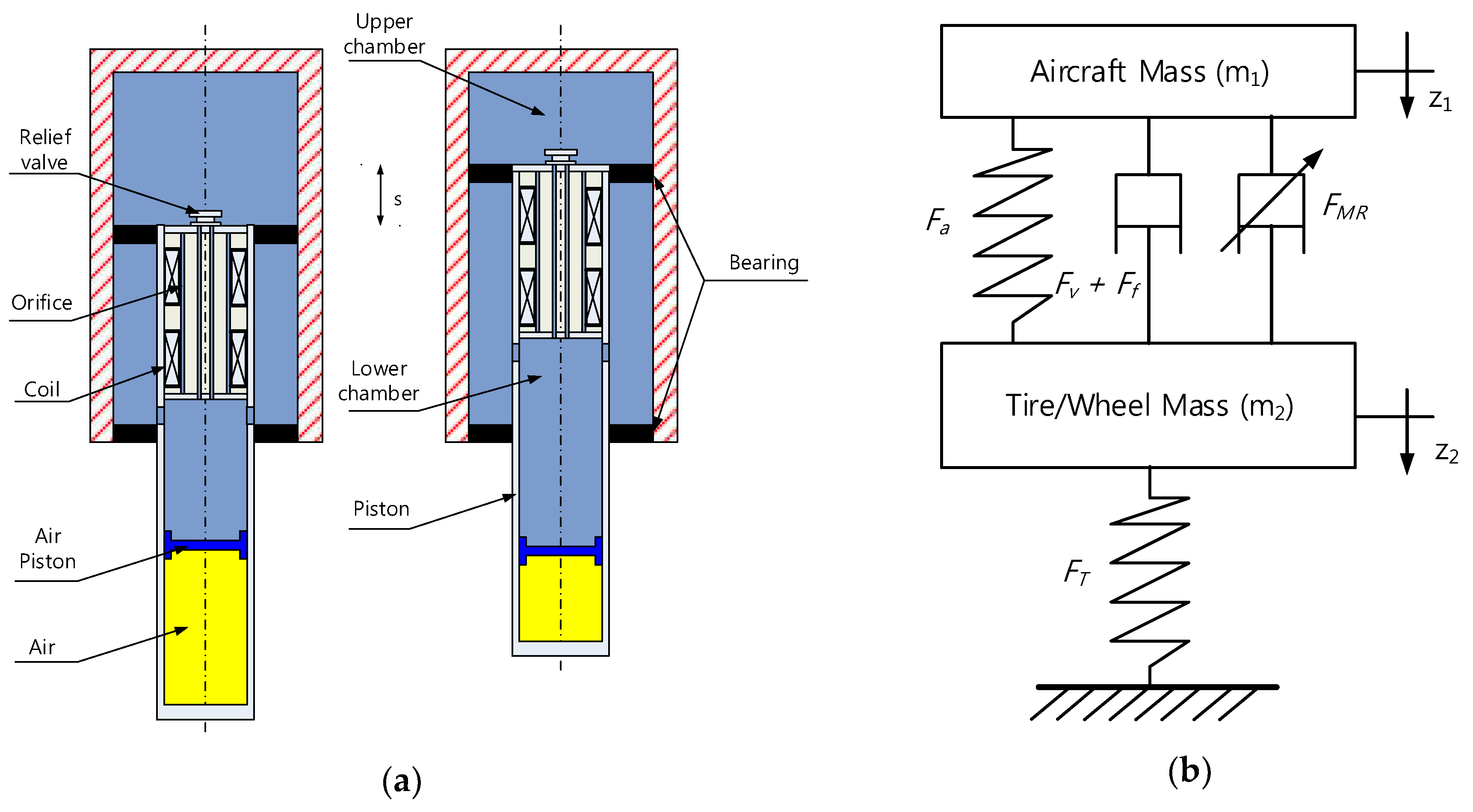
In this paper, the mathematical model of an aircraft landing gear is taken from the previous work [18,19,20]. Figure 1 depicts the structural and dynamic models of a single landing gear equipped with an MR damper. Following the movement of the piston, MR fluid flows through narrow orifices in the piston head from one chamber to the other one. And, it creates viscous damping force from the pressure difference between the chambers. In addition to this general oleo-pneumatic structure, the orifices are surrounded by two coils, of which the magnetic field is controlled by applying current. When an electric current is applied, micron-sized particles in the MR fluid are rearranged along the magnetic field around the coils. This phenomenon causes the MR fluid to transform into a viscoelastic solid in milliseconds resulting in additional pressure difference and damping force. Thus, the MR damping force can be controlled by changing the electric current applied to the damper.
Typically, the total force of an MR damper can be expressed as a combination of hydraulic force Fh, pneumatic force Fa, and friction force Ff:
The hydraulic force, which is the sum of the viscous force Fv and the controllable MR damping force FMR, can be given by:
where s = z1 − z2 ≥ 0 denotes the piston stroke, which is the difference between the sprung and un-sprung masses’ displacement z1, z2, respectively, and u is the control input. The air chamber is filled with pressurized gas to provide an elastic force when compressed. The gas undergoes a polytropic process, and thus, the pneumatic force can be expressed as:
The friction force appears due to the contact of the piston and cylinder, which can be expressed by [20]:
FT denotes the tire force by the deflection of the wheel tire, and is expressed as:
where kt is the tire stiffness, and b is the polynomial index of the tire elasticity. In Equation (5), the tire is assumed to always contact with the ground, and thus, the un-sprung mass’s displacement z2, i.e., the tire deformation, is always positive: z2 ≥ 0.
As an aircraft touches down on the ground with its landing gear, the upper and lower bodies of the landing gear move separately. The equations of motion are given as:
where m1 is the sprung mass, including the part of the aircraft mass supported by the landing gear, crew, pilot, and the upper components of the landing gear, such as the cylinder. The un-sprung mass m2 includes the piston, wheel, and other components below the damper. v is the sink speed of aircraft at the touchdown. All parameter values of the landing gear used in this paper are given in Table 1.
3. Problem Definition
3.1. Landing Gear System Concept
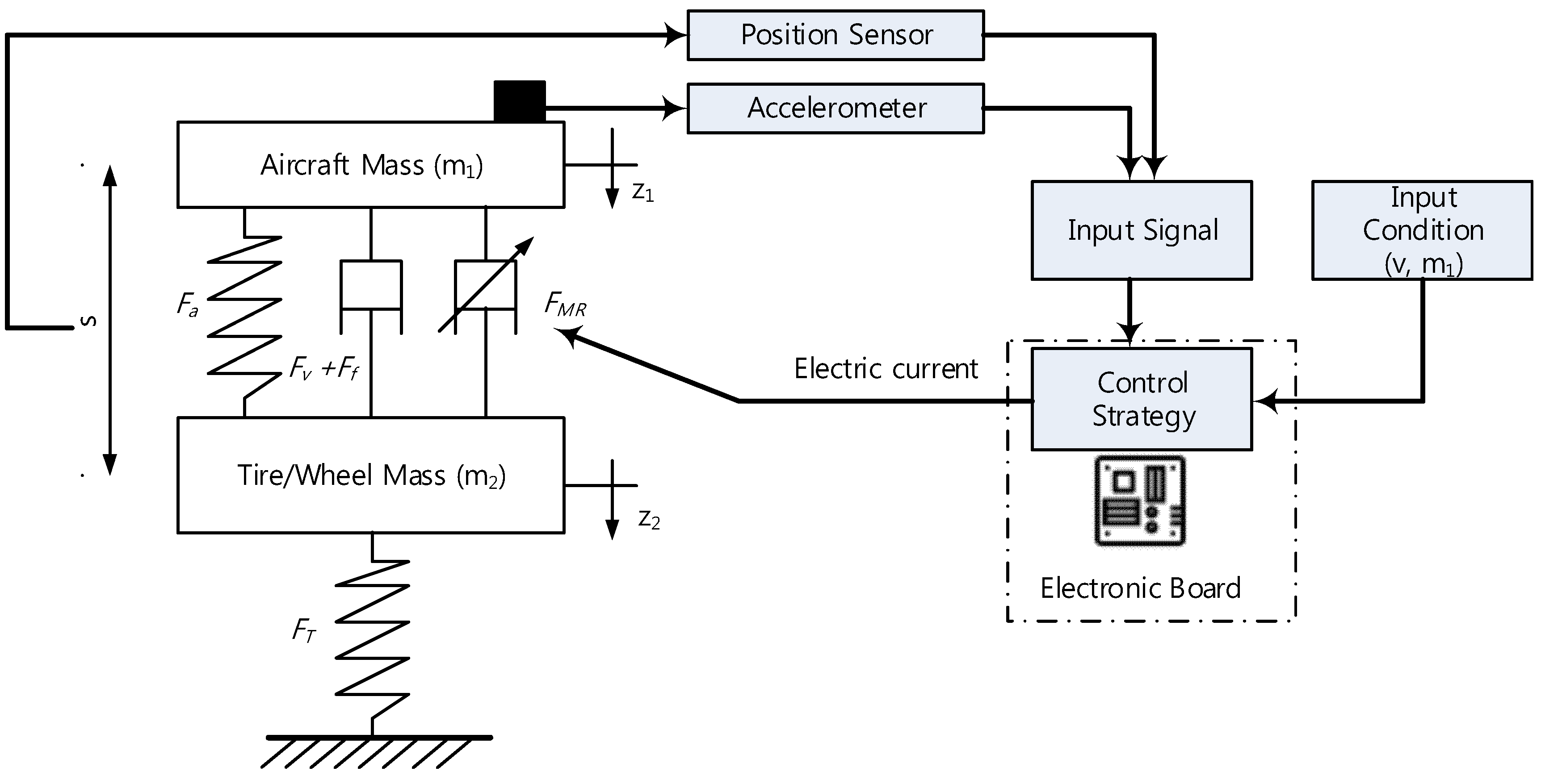
Figure 2 shows the concept of a landing gear system equipped with an MR damper. For reducing the weight and the cost of equipment, the system has only two sensors, which are a position sensor and an accelerometer. After receiving the input signal from sensors, the control algorithm computes the required electrical current, which is then applied to the MR damper for generating the damping force. The key part of this system is the development of the control strategy to improve the performance of the landing gear.
3.2. Control Targets
The aircraft must be able to touch down in different landing scenarios. The landing scenarios can be characterized by two basic parameters: aircraft mass and sink speed. The ranges of varying aircraft mass and sink speed considered in this paper are shown in Table 1. To build the control system easily, accurately measuring those parameters is crucial. Whereas it is possible to estimate the aircraft sink speed with a ground proximity sensor or an accelerometer, it is unlikely to obtain highly accurate aircraft mass estimates because it depends on the remaining fuel mass and payload. In this paper, two methods for mass estimation are given.
- -
- First method:Before take-off, only the pneumatic force from the landing gear damper sustains the aircraft mass. From Equations (3) and (6), the mass of aircraft can be estimated by:
Before landing, the mass of aircraft reduces by the fuel consumption Δmgas. Thus, the aircraft mass can be calculated by:
The advantage of this method is that it is fast, and the estimated value can be predicted before landing. However, the accuracy of this method depends on the measurement of the remaining fuel.
- -
- Second method:The mass can be estimated by rearranging Equation (6),where is the estimate of the unknown parameter m1. Because of sensor noise, this estimation is hardly stable, and the denominator can be zero. Appling the least squares method, the mass estimation is given by:
The estimate is updated over time. In some sense, it is averaging the effects of measurement noise. Note that the denominator in Equation (12) is always increasing and non-zero. The convergence of the estimation can be proved as follows. Equation (12) is rewritten as:
The derivative of Equation (13) is given by:
Combining Equations (6) and (14), we further obtain the time derivative of the estimate :
Then, a Lyapunov function candidate can be proposed as below:
From Equations (15) and (16), the derivative of the Lyapunov function is found to be:
The Lyapunov condition is satisfied, and, thus, the estimation converges (). Although this method can estimate aircraft mass online, however, the accurate estimation is limited by the model validity and accuracy.
Some parametric uncertainties are impossible to estimate without incurring excessive cost. Such factors as undesirable wind, ground effect, and runway unevenness can impact the landing performance of an aircraft landing gear. In addition, some parameters are impossible to measure or estimate accurately, such as viscous damping coefficient and friction force. In this research, friction force is assumed to be much less than the other forces, and its uncertainty can be ignored. However, viscous force is a critical factor in absorbing kinetic energy at landing, and thus, its parametric uncertainty is considered. Because of noise and disturbance from the environment, the viscous damping coefficient can be changed within bound; the values used in this work are shown in Table 1. Moreover, temperature can affect the pressure of air or impact on viscous damping [21]. In this research, the relationship of temperature and pressure is assumed to follow the equation below:
Overall, the targets of the proposed control algorithm are given:
- The controller improves the performance of the landing gear.
- The controller provides an adaptive ability under different landing scenarios.
- The controller can deal with unmodelled uncertainties and disturbances.
4. Algorithm Control Designation
4.1. Performance Measure of Impact Energy Absorption
After a landing gear touches the ground, the initial kinetic and potential energy of the system is absorbed and dissipated with the back-and-forth motion of the damper in the landing gear. The work done by the damper can be calculated as the integral of the damper force Fd over the stroke. The total work done by the damper until the landing gear system is stabilized and is then equal to the initial kinetic and potential energy, and thus it is constant in a given landing condition. The total energy absorber efficiency is defined as the ratio between the total work done by the damper during landing and the product of the maximum force Fmax and stroke smax during the same time period. The latter means the maximum possible work by the force Fmax traversing smax. Therefore, the total energy absorber efficiency η is the measure of damper performance of absorbing the dynamic energy through the whole period of impact absorption:
In [4,22,23,24], the shock strut efficiency is used to assess the damper performance, which is defined as the ratio η1 between the damper work from 0 to smax and the product of the maximum force and stroke. η1 approximates η because the most impact energy is absorbed and dissipated in the first contraction phase of the damper moving from 0 to smax. However, there is still more than 10% of the total energy stored in the air spring at smax, and thus, the damper will still actively oscillate until it arrives at the equilibrium state. In this paper, the total energy absorber efficiency η is used instead, in order to evaluate the damper efficiency of the landing impact absorption in the overall process.
4.2. Adaptive Hybrid Controller
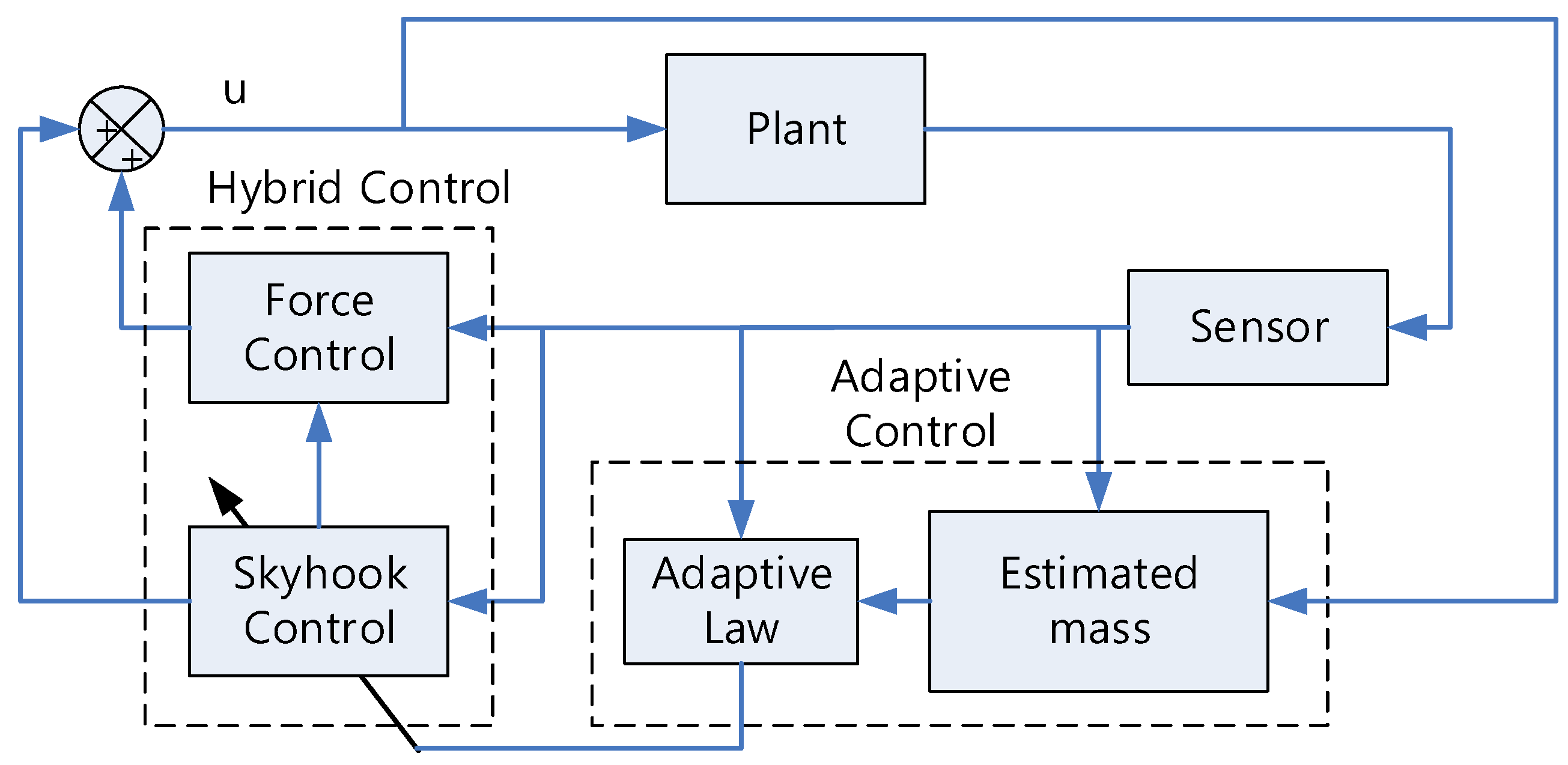
In this work, a self-tuning control (STC) [25] concept is applied to deal with the different landing scenarios. Figure 3 describes the flow of an adaptive hybrid controller. With the measurements from at least two types of sensors (e.g., a position sensor which measures the stroke, and an accelerometer, which measures the acceleration of the aircraft), the adaptive controller requires the estimates of aircraft mass and sink speed for calculating an appropriate skyhook gain and target damping force for a hybrid control block.
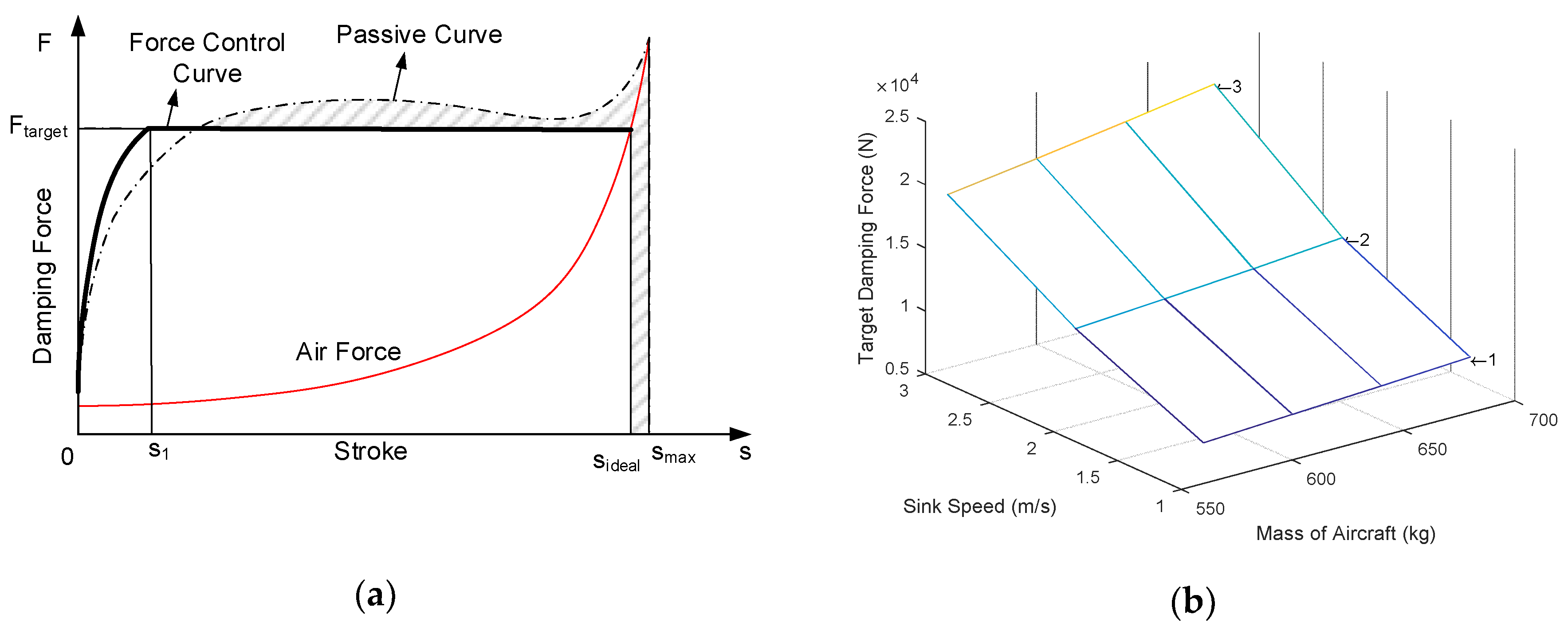
The hybrid control [18] is a combination of the force control [26] and the skyhook control [27] methods. The force control is a method of maximizing the impact energy absorption efficiency of a damper by filling up the gap between Fmax and damper force curve over stroke. Figure 4a depicts a typical force-stroke curve of passive damping. Since the damper force is not always maximized to Fmax, one may expect it will be more efficient if the damper force is kept constant for as long as possible during the first contraction of the damper. In the force control, a simple base controller or non-controlled passive damping is used until the stroke velocity reaches the first local maximum after touchdown, and then the damping force is controlled to be a constant value, called the target damping force Ftarget. The base controller is designed to produce Ftarget at s1, where its velocity is maximized , and lower magnitude thereafter. As in [4], the target damping force is defined as the damper work from 0 to smax divided by 90% of the maximal stroke in passive damping:
Then, the control input force is given by:
This target damping force depends on the dynamic energy at touchdown, which is characterized by the aircraft mass m1 and initial sink speed v. Thus, the target value should be defined for each unique landing condition. To build a table of target damping force over various aircraft mass and sink speed values, multiple numerical simulations of the damper without any control were executed covering a wide variety of the parameters. The results are plotted in Figure 4b: the target damping force increases with larger aircraft mass and faster sink speed.
The base controller used in this paper is the skyhook controller, and it runs before the force control becomes active. The skyhook control produces additional damping input against the velocity of the sprung mass . It is a widely used method in suspension systems because it is simple to implement and requires a minimal number of system states, i.e., and . By tuning its damping gain, the impact energy absorption efficiency of a semi-active damper can be significantly increased over passive damping. The rule of the skyhook control in a semi-active damper is expressed as:
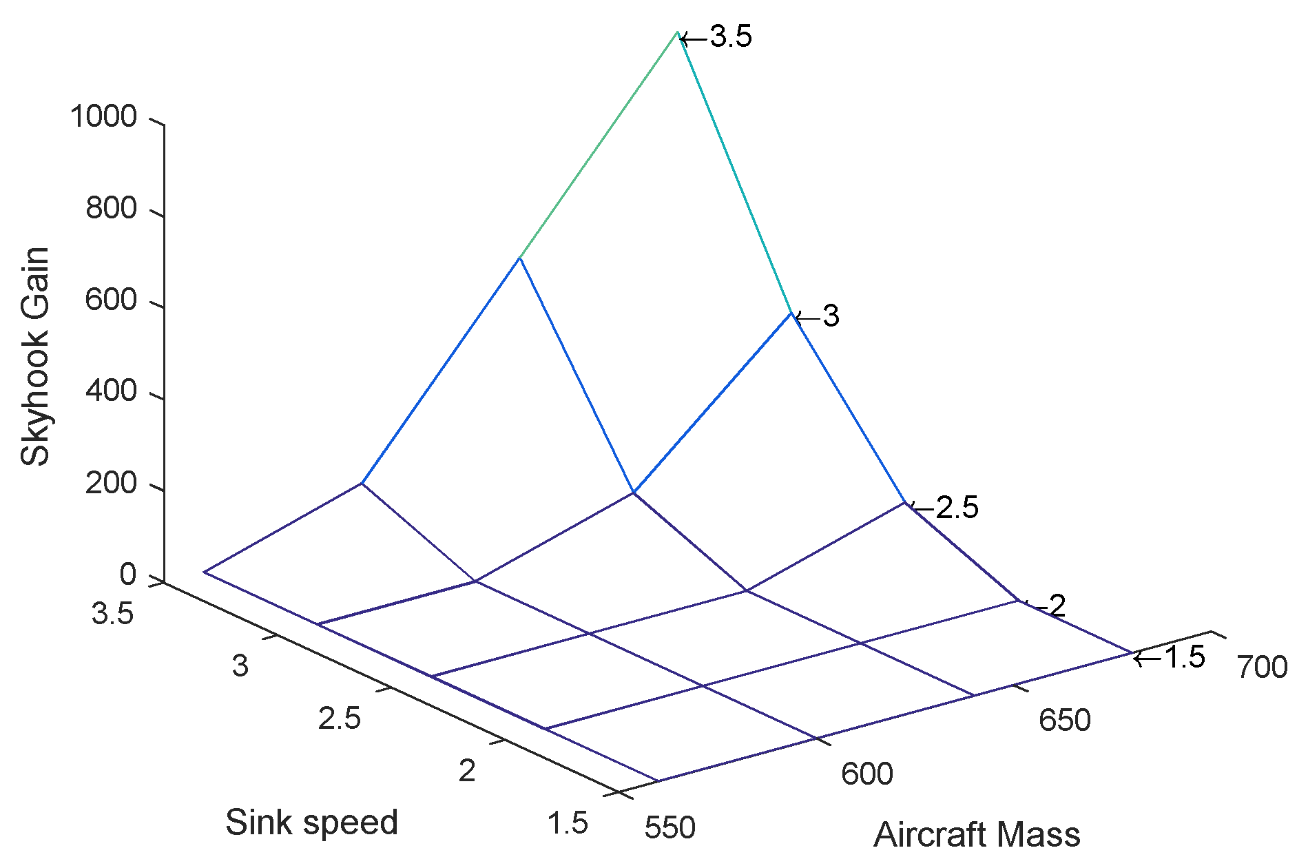
where Csky is the skyhook gain. Unlike general types of differential control, the control input should be 0 when and are opposite in sign because the damping force of an MR damper is only applied in the opposite direction of the relative movement of the piston and cylinder. Since a base controller for the force control should create damping force Fd = Ftarget at s1, the skyhook gain is determined by:
where and are the maximum upper mass velocity and corresponding passive damper force without control. The skyhook gain surface is shown in Figure 5: the passive damping is used instead of the skyhook control when mass and sink speed are low so that Csky = 0; in the case of higher mass and sink speed, a non-zero skyhook control input is applied and the skyhook gain rises.
4.3. Sliding Mode Controller-Adaptive Hybrid Control
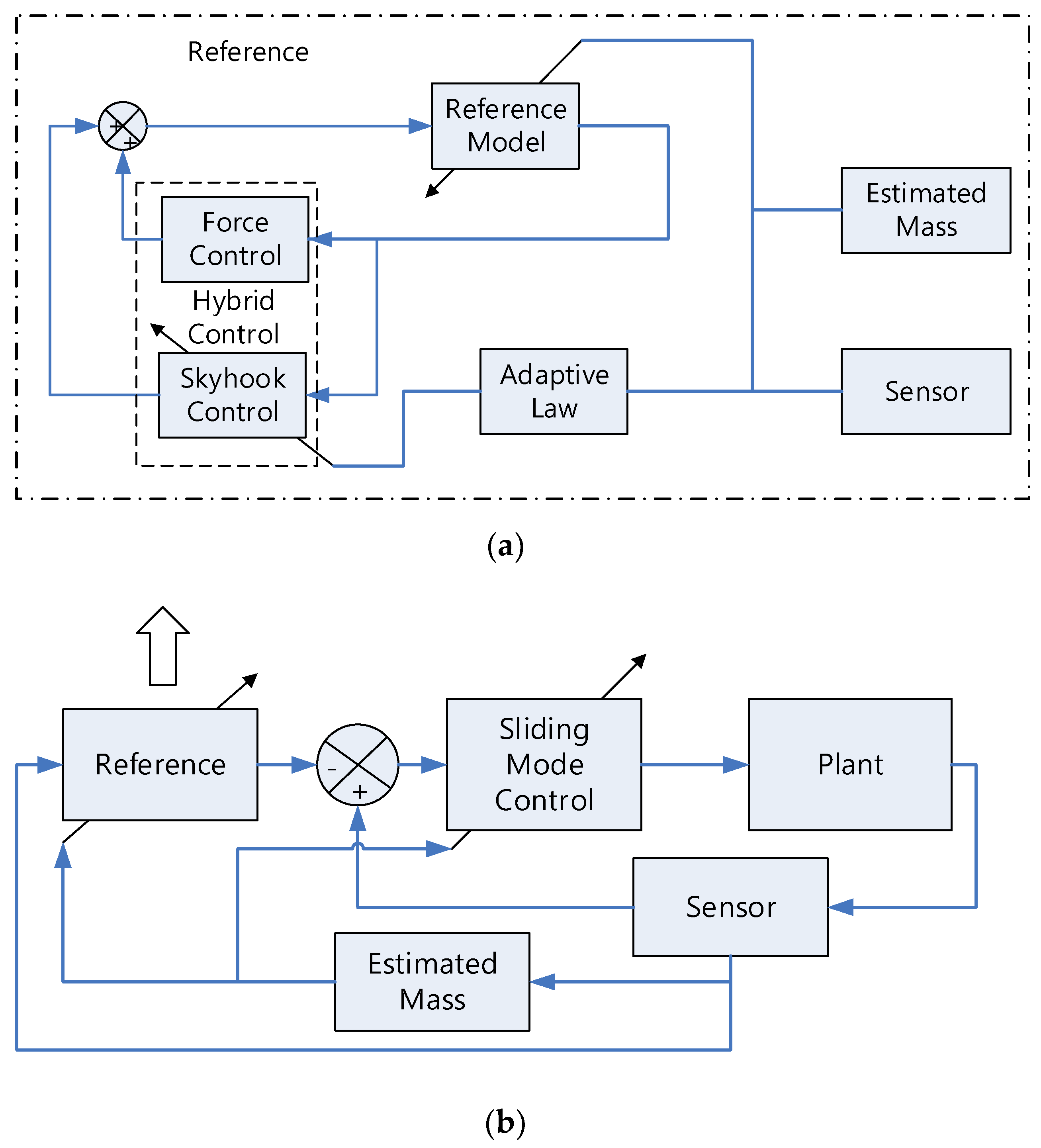
Sliding Mode Control (SMC) is the most common algorithm used to manage uncertainties. The main task of SMC is to drive the plant according to the reference model. Figure 6a shows the reference module to calculate the history of the reference signal (zd1). Before the landing gear touches down, the mathematical model with an adaptive hybrid control algorithm is executed. This progress depends on the estimated mass and sink speed explained in the previous chapter. Then, the tracking error is calculated as the difference between the signal sensor (z1) and the reference signal (zd1), which is shown in Figure 6b. Next, the SMC system is developed based on the tracking error and the operating principle of the MR damper.
Following [28], the sliding surface can be expressed by:
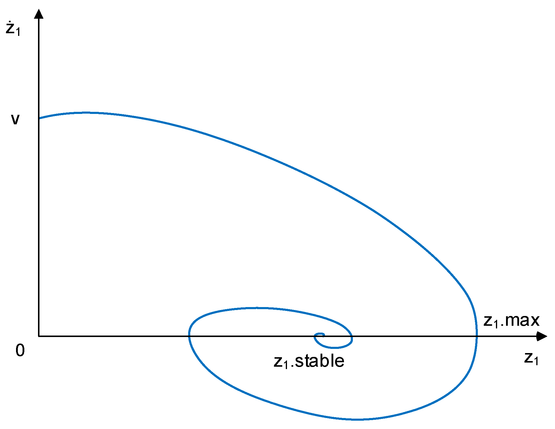
where is the tracking error, λ is the slope of the sliding surface line. Figure 7 shows the state phase of a typical aircraft. The motion starts from (0, v) passes (z1.max, 0) and ends at (z1.stable, 0). Because the start point is on the vertical line, the slope value can be chosen λ = 0 to reduce the time to reach the sliding surface. The control law can be given as:
where sat is the saturation function [28], and ξ = 0.1 is the boundary thickness. The estimated control law, is designed as:
and ξ = 0.1 is boundary thickness, discontinuous control gain, k is selected satisfying the inequality below:
Because MR damper is a semi-active system, the control law must use the following rule:
To check the stability of the controller, the candidate of the Lyapunov function is given by:
The derivative of Equation (29) is:
The Lyapunov condition is satisfied; thus, the controller is stable to deal with uncertainties. However, the control input can be infinite to make the system reside in the sliding surface. Because the physical force output from an MR damper is bounded as in Table 1, the stability proof of the proposed control algorithm might be valid with only a limited level of uncertainties and disturbances.
5. Simulation Results and Discussion
To verify the effectiveness of the controller, numerical simulations with different control methods were performed. Passive damping, skyhook control, and adaptive hybrid control were applied and compared with the SMC-adaptive hybrid control. All simulations and computations were carried out using MATLAB with SIMSCAPE-SIMULINK. The outputs of controllers were investigated in terms of the maximum damper force, the maximum stroke, and the maximal total energy absorber efficiency under various aircraft weights and sink speeds.
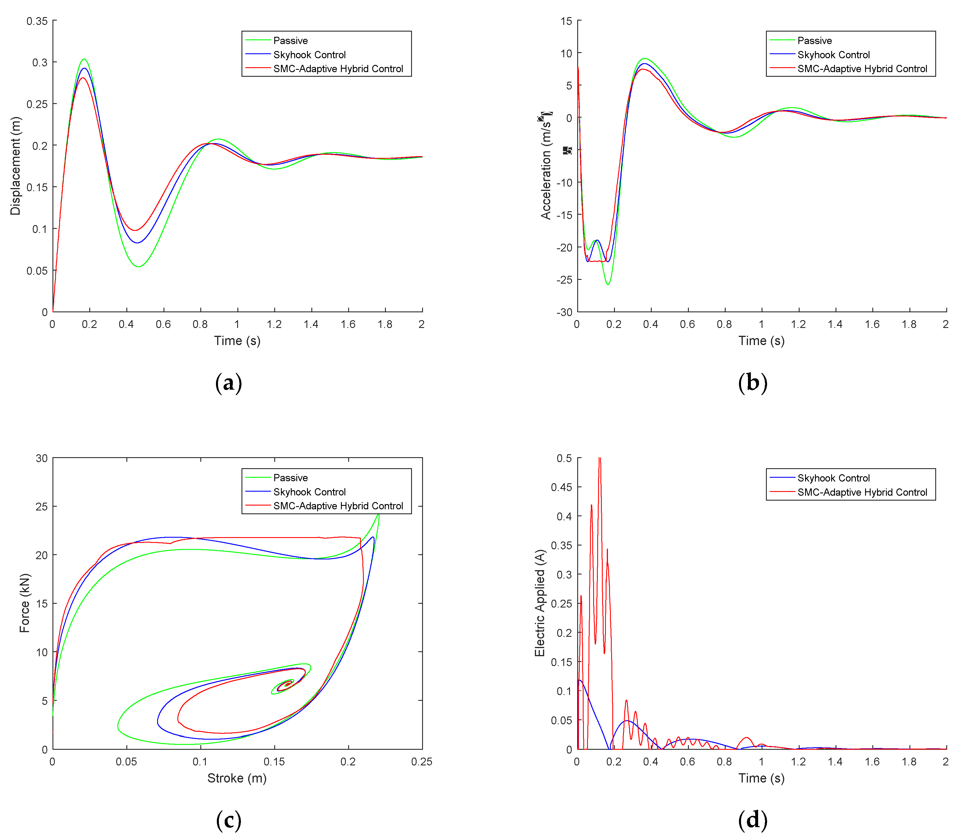
Both Figure 8 and Table 2 show the simulation results in the case of a heavy load and high speed (m1 = 680 kg and v = 3 m/s). The SMC-adaptive hybrid control shows the best performance compared with the passive damper and skyhook control. The damper using the proposed controller produces the lowest absolute displacement and aircraft acceleration in magnitude. This means that the proposed controller is able to reduce more vibration in the landing gear system, which may increase passenger comfort. In addition, the proposed controller improves the total energy absorber efficiency of the damper to nearly 94%, which is 5% and 15% higher than the skyhook control and passive damping, respectively. Moreover, the comparison results of different sink speeds and masses are shown in Table 3. The results show that the proposed controller has the smallest value of both maximum stroke and damper force, and the total energy absorber efficiency is up to about 10% more than that of the skyhook controller.
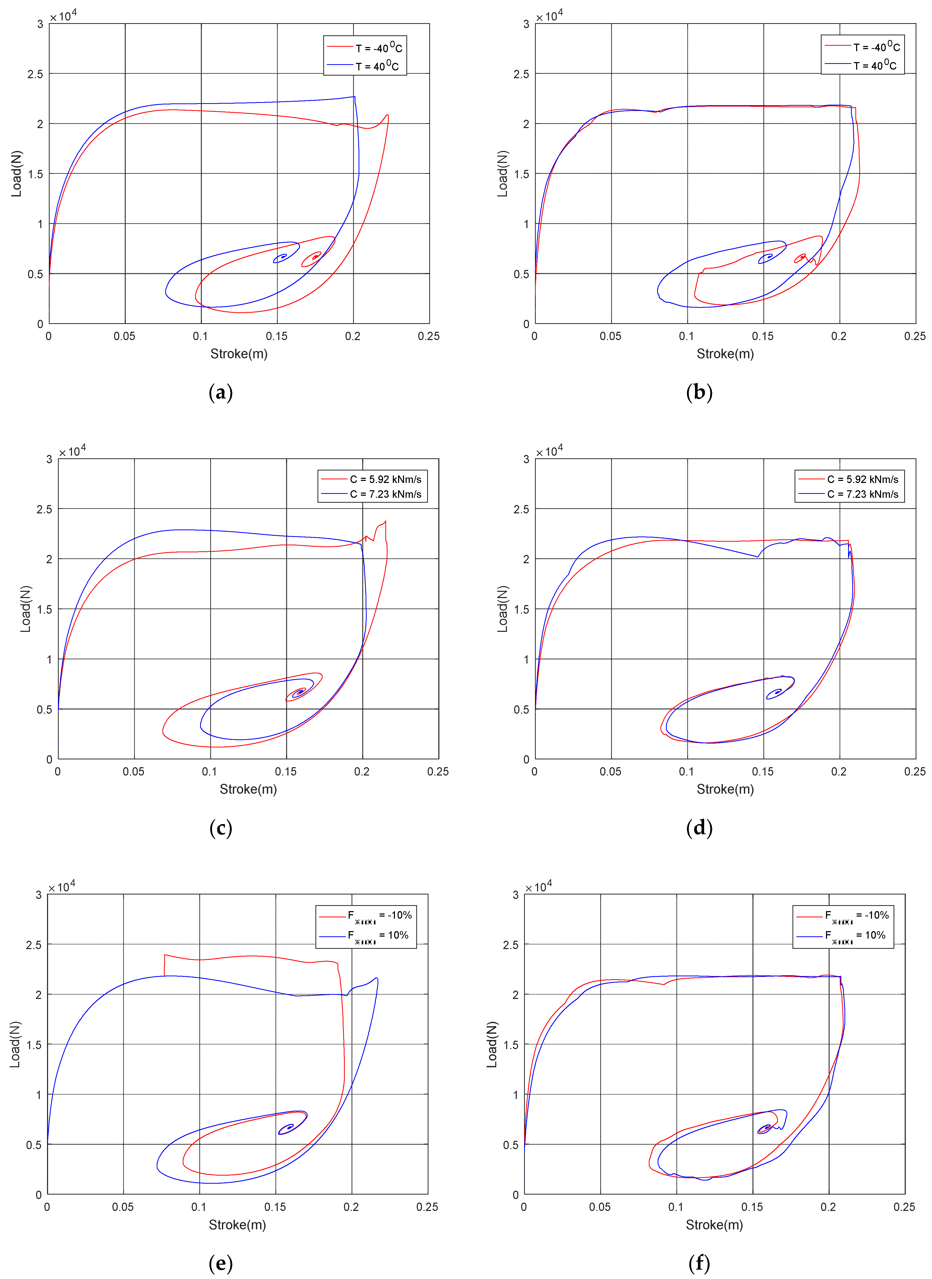
Figure 9 and Table 4 show the comparative damping performances of the adaptive hybrid control and SMC-adaptive hybrid control under parameter uncertainties. The controllers are compared with three varying parameters picked as the uncertainties in landing: the change of air pressure with ambient temperature, inaccuracy of viscous damping coefficient, and the error of damping force estimate. Under the parameter variation, the performance of the adaptive hybrid control is degraded. In particular, the shock absorber efficiency reduces by about 10% when the viscous damping coefficient decreases by 10%. The maximum damping force increases by 10% when the damper force is underestimated by 10%. On the other hand, the SMC-adaptive hybrid controller maintains the performances under the parameter variation, and thus, its robustness under parametric uncertainties in landing is verified.
6. Conclusions
This research investigated the robust adaptive control for a single landing gear system equipped with an MR damper. With a mathematical model of the landing gear, a robust controller based on the adaptive hybrid control and sliding mode control algorithm was proposed. Comparative numerical simulations under the various landing conditions (i.e., aircraft weights and sink speeds) and parametric uncertainties (i.e., ambient temperature, viscous damping coefficient, damping force estimate error) were conducted to analyze the effectiveness of the proposed control algorithm. From the simulations, it was verified that the damper using the proposed controller has acceptable and stable performance with high total energy absorber efficiency and an improved adaptability and robustness in differing landing scenarios and uncertainties.
Both the adaptive hybrid control and sliding mode control are built on a mathematical model. Thus, the difficulty of this approach is to develop an accurate mathematical model. Therefore, as future work, drop-test experiments of a landing gear system can be set up to verify the damper model and the performance of the control. On the other hand, because the damping process of a landing gear occurs in very short time, the time delay of an MR damper can be a crucial factor in determining the effectiveness of control. Thus, to deal with the time delay, control methods based on artificial intelligent techniques, such as a reinforcement neural network or genetic algorithm neural network, can be applied to the MR damper.
Author Contributions
This study was initiated and designed by J.-H.H. The numerical simulations were completed by Q.V.L. The data analysis, and writing the paper were completed by Q.V.L. and D.-S.J. The suggestions for the simulation design and paper writing were done by D.-S.J. and J.-H.H. All authors have read and agreed to the published version of the manuscript.
Funding
This work was funded by the Ministry of Trade, Industry & Energy (MOTIE, Korea).
Acknowledgments
This work was supported by the Technology Innovation Program (intelligent landing gear with variable damping force for 1500lb class) (10073291).
Conflicts of Interest
The authors declare no conflict of interest.
References
- Currey, N.S. Aircraft Landing Gear Design: Principles and Practices; American Institute of Aeronautics and Astronautics: Reston, WA, USA, 1988. [Google Scholar]
- Hakan, Y.; Mert, S. Active control of a non-linear landing gear system having oleo pneumatic shock absorber using robust linear quadratic regulator approach. Proc. Inst. Mech. Eng. Part G J. Aerosp. Eng. 2018, 232, 2397–2411. [Google Scholar]
- Sivakumar, S.; Haran, A.P. Mathematical model and vibration analysis of aircraft with active landing gears. J. Vib. Control 2015, 21, 229–245. [Google Scholar] [CrossRef]
- Dong-su, W.U.; Hong-bin, G.U.; Hui, L.I.U. GA-based model predictive control of semi-active landing gear. Chin. J. Aeronaut. 2007, 20, 47–54. [Google Scholar]
- Batterbee, D.C.; Sims, N.D.; Stanway, R.; Wolejsza, Z. Magnetorheological landing gear. Part 1: A design methodology. Smart Mater. Struct. 2007, 16, 2429–2440. [Google Scholar] [CrossRef] [Green Version]
- Batterbee, D.C.; Sims, N.D.; Stanway, R.; Rennison, M. Magnetorheological landing gear. Part 2: Validation using experimental data. Smart Mater. Struct. 2007, 35, 897–902. [Google Scholar]
- Lee, D.Y.; Nam, Y.J.; Yamane, R.; Park, M.K. Performance evaluation on vibration control of MR landing gear. J. Phys. Conf. Ser. 2009, 149. [Google Scholar] [CrossRef]
- Wereley, N.M.; Kamath, G.M.; Madhavan, V. Hysteresis Modelling of Semi-Active Magnetorheological Helicopter Dampers. J. Intell. Mater. Syst. Struct. 1999, 10, 624–633. [Google Scholar] [CrossRef]
- Han, Y.-M.; Choi, S.-B. Fluid Technology Applications in Vehicle Systems; CRC Press Taylor & Francis Group: Boca Raton, FL, USA, 2013. [Google Scholar]
- Mikułowski, G.; Jankowski, Ł. Adaptive landing gear: Optimum control strategy and potential for improvement. Shock Vib. 2009, 16, 175–194. [Google Scholar] [CrossRef]
- Dong, X.M.; Xiong, G.W. Vibration attenuation of magnetorheological landing gear system with human simulated intelligent control. Math. Probl. Eng. 2013, 2013, 1–13. [Google Scholar] [CrossRef] [Green Version]
- Choi, Y.-T.; Robinson, R.; Hu, W.; Wereley, N.M.; Birchette, T.S.; Bolukbasi, A.O.; Woodhouse, J. Analysis and Control of a Magnetorheological Landing Gear System for a Helicopter. J. Am. Helicopter Soc. 2016, 61, 1–8. [Google Scholar] [CrossRef]
- Zhang, H.; Wang, E.; Zhang, N.; Min, F.; Subash, R.; Su, C. Semi-active sliding mode control of vehicle suspension with magneto-rheological damper. Chin. J. Mech. Eng. 2015, 28, 63–75. [Google Scholar] [CrossRef]
- Lu, K.-C.; Loh, C.-H.; Yang, J.N.; Lin, P.-Y. Decentralized sliding mode control of a building using MR dampers. Smart Mater. Struct. 2008, 17, 1–15. [Google Scholar] [CrossRef]
- Zapateiro, M.; Pozo, F.; Rossell, J.M.; Karimi, H.R.; Luo, N. Landing gear suspension control through adaptive backstepping techniques with H∞ performance. Ifac Proc. Vol. 2011, 18, 4809–4814. [Google Scholar] [CrossRef] [Green Version]
- Fallah, M.S.; Long, S.H.; Xie, W.F.; Bhat, R. Robust Model Predictive Control of Shimmy Vibration in Aircraft Landing Gears. J. Aircr. 2008, 45, 1872–1880. [Google Scholar] [CrossRef]
- Kang, B.-H.; Han, C.; Choi, S.-B. A sky-ground hook controller for efficiency enhancement of aircraft landing gear with MR damper. In Proceedings of the Volume 10967, Active and Passive Smart Structures and Integrated Systems XIII, 1096706, Denver, CO, USA, 21 March 2019. [Google Scholar]
- Tak, J.M.; Viet, L.Q.; Hwang, J.-H. Hybrid Control of Aircraft Landing Geare using Magnetorheological Damper. J. Aerosp. Syst. Eng. 2018, 12, 1–9. [Google Scholar]
- Han, C.; Kang, B.-H.; Choi, S.-B.; Tak, J.M.; Hwang, J.-H. Control of Landing Efficiency of an Aircraft Landing Gear System with Magnetorheological Dampers. J. Aircr. Aircr. 2019, 56, 1980–1986. [Google Scholar] [CrossRef]
- H, C.; Kim, B.-G.; Choi, S.-B. Design of a New Magnetorheological Damper Based on Passive Oleo-Pneumatic Landing Gear. J. Aircr. 2018, 55, 2510–2520. [Google Scholar]
- Ferdaus, M.M. Temperature Effect Analysis on Magneto-Rheological Damper’s Performance. J. Autom. Control. Eng. 2014, 2, 392–396. [Google Scholar] [CrossRef]
- Daniels, J.N. A method for landing gear modeling and simulation with experimental validation. In NASA Contractor Report 201601; National Aeronautics and Space Administration: Washington, DC, USA, 1996; pp. 1–97. [Google Scholar]
- Li, Y.; Jiang, J.Z.; Neild, S.A.; Wang, H. Optimal Inerter-Based Shock–Strut Configurations for Landing-Gear Touchdown Performance. J. Aircr. 2017, 54, 1901–1909. [Google Scholar] [CrossRef] [Green Version]
- Wang, X.; Carl, U. Fuzzy control of aircraft semi-active landing gear system. In Proceedings of the 37th Aerospace Sciences Meeting and Exhibit, Hannover, Germany, 11–14 January 1999. [Google Scholar]
- Fidan, B.; loannou, P. Adaptive Control. Tutorial; Society for Industrial and Applied Mathematics: Philadelphia, PA, USA, 2006. [Google Scholar]
- Hyun, Y.-O.; Hwang, J.-U.; Hwang, J.-H.; Bae, J.-S.; Lim, K.-H.; Kim, D.-M.; Kim, D.-W.; Park, M.-H. Force Control of Main Landing Gear using Hybrid Magneto-Rheological Damper. J. Korean Soc. Aeronaut. Space Sci. 2010, 38, 315–320. [Google Scholar]
- Karnopp, D.; Crosby, M.J.; Harwood, R.A. Vibration control using semi-active force generators. J. Manuf. Sci. Eng. 1974, 96, 619–626. [Google Scholar] [CrossRef]
- Slotine, J.-J.E.; Li, W. Applied Nonlinear Control; Prentice Hall International Inc.: Upper Saddle River, NJ, USA, 1991. [Google Scholar]
Figure 1.
Dynamic model of a single landing gear equipped with a magnetorheological (MR) damper: (a) structure of the landing gear; (b) schematic model of the landing gear.
Figure 1.
Dynamic model of a single landing gear equipped with a magnetorheological (MR) damper: (a) structure of the landing gear; (b) schematic model of the landing gear.

Figure 2.
Concept of a landing gear system.

Figure 3.
Adaptive hybrid control algorithm.

Figure 4.
Force curve and target damping force of the force control: (a) force-stroke curve; (b) the relationship between target damping force and landing condition parameters.
Figure 4.
Force curve and target damping force of the force control: (a) force-stroke curve; (b) the relationship between target damping force and landing condition parameters.

Figure 5.
Skyhook gain surface.

Figure 6.
Sliding mode control-adaptive hybrid control algorithm. (a) Reference part. (b) Main part.
Figure 6.
Sliding mode control-adaptive hybrid control algorithm. (a) Reference part. (b) Main part.

Figure 7.
State phase of damper.

Figure 8.
The simulation results of the MR damper using the passive damping, skyhook control, and sliding mode control (SMC)-adaptive hybrid control in the case of m1 = 680 kg and v = 3 m/s: (a) displacement of the aircraft; (b) acceleration of the aircraft; (c) load-stroke curve; (d) electric current.

Figure 9.
The force-stroke curves of damper using the adaptive hybrid control (a,c,e) and SMC-adaptive hybrid control (b,d,f) under parametric uncertainties (m1 = 680 kg and v = 3 m/s). (a,b) Differing temperatures; (c,d) differing damping viscous efficiencies; (e,f) differing damping force errors.
Figure 9.
The force-stroke curves of damper using the adaptive hybrid control (a,c,e) and SMC-adaptive hybrid control (b,d,f) under parametric uncertainties (m1 = 680 kg and v = 3 m/s). (a,b) Differing temperatures; (c,d) differing damping viscous efficiencies; (e,f) differing damping force errors.


Table 1.
Landing gear parameters.
| Symbol | Quantity | Value | Unit |
|---|---|---|---|
| Ap | cross area of head piston | 2.5 × 10⁻³ | m2 |
| b | tire force index | 1.13 | |
| C | viscous damping coefficient | 5.9~7.2 | Ns/m |
| Db | moment arm of tire force from the centerline of the piston | 0.3 | m |
| Dv | minimum distance between the piston head and the lower seal | 0.3 | m |
| g | gravitational acceleration | 9.81 | m/s2 |
| m1 | sprung mass (aircraft mass) | 560~680 | kg |
| m2 | un-sprung mass | 18 | kg |
| n | polytropic process index | 1.3 | |
| p0 | initial air chamber charging pressure | 636–964 | kPa |
| pATM | atmospheric pressure | 101.3 | kPa |
| kT | tire force constant | 412 | kN/m |
| v | initial sink speed of aircraft at touchdown | 1.5–3.5 | m/s |
| V0 | initial air chamber volume | 6.37 × 10⁻⁴ | m3 |
| µ | friction coefficient for bearing | 0.1 | |
| u | control input (MR force) | 0~10 | kN |
| T | environment temperature | −40~40 | °C |
All parameters are referenced in [18].
Table 2.
The efficiency of the damper using the passive damper, skyhook control, and SMC-adaptive hybrid control in the case of m1 = 680 kg and v = 3 m/s.
Table 2.
The efficiency of the damper using the passive damper, skyhook control, and SMC-adaptive hybrid control in the case of m1 = 680 kg and v = 3 m/s.
| Maximum of Stroke smax (m) | Maximum of Damping Force Fmax (kN) | Total Energy Absorber Efficiency η (%) | |
|---|---|---|---|
| Passive damper | 0.221 | 24.2 | 80.4 |
| Skyhook control | 0.217 | 21.8 | 90.6 |
| SMC-adaptive hybrid control | 0.210 | 21.8 | 93.8 |
Table 3.
The performance of the damper using passive damping, skyhook control, and SMC-adaptive hybrid control under various aircraft masses and sink speeds.
Table 3.
The performance of the damper using passive damping, skyhook control, and SMC-adaptive hybrid control under various aircraft masses and sink speeds.
| Passive Damper | Skyhook Control | SMC-Adaptive Hybrid Control | |||||||
|---|---|---|---|---|---|---|---|---|---|
| Fmax (kN) | smax (m) | η (%) | Fmax (kN) | smax (m) | η (%) | Fmax (kN) | smax (m) | η (%) | |
| m1 = 560 kg | |||||||||
| v = 1.5 m/s | 11.6 | 0.162 | 79.8 | 12.2 | 0.155 | 78.9 | 11.7 | 0.144 | 89.0 |
| v = 2.5 m/s | 16.9 | 0.193 | 81.1 | 18.0 | 0.186 | 79.3 | 17.2 | 0.165 | 93.8 |
| v = 3.5 m/s | 22.4 | 0.217 | 90.4 | 23.8 | 0.212 | 86.8 | 22.6 | 0.209 | 93.0 |
| m1 = 600 kg | |||||||||
| v = 1.5 m/s | 11.9 | 0.172 | 80.9 | 12.5 | 0.165 | 79.7 | 12.1 | 0.150 | 90.9 |
| v = 2.5 m/s | 17.2 | 0.201 | 83.4 | 18.2 | 0.195 | 81.1 | 17.4 | 0.178 | 92.9 |
| v = 3.5 m/s | 24.5 | 0.221 | 87.6 | 24.2 | 0.217 | 90.1 | 23.7 | 0.203 | 95.4 |
| m1 = 640 kg | |||||||||
| v = 1.5 m/s | 12.0 | 0.181 | 82.2 | 12.7 | 0.174 | 80.7 | 12.1 | 0.159 | 92.9 |
| v = 2.5 m/s | 17.5 | 0.207 | 85.9 | 18.5 | 0.201 | 83.2 | 18.3 | 0.181 | 94.1 |
| v = 3.5 m/s | 27.6 | 0.224 | 82.1 | 24.9 | 0.221 | 92.1 | 24.5 | 0.216 | 95.6 |
| m1 = 680 kg | |||||||||
| v = 1.5 m/s | 12.3 | 0.188 | 83.9 | 12.9 | 0.183 | 82.1 | 12.3 | 0.170 | 92.8 |
| v = 2.5 m/s | 18.6 | 0.212 | 84.7 | 18.8 | 0.207 | 85.6 | 18.4 | 0.196 | 92.3 |
| v = 3.5 m/s | 30.7 | 0.227 | 77.9 | 27.9 | 0.224 | 86.4 | 25.5 | 0.220 | 96.4 |
Table 4.
The performance of the damper using the adaptive hybrid control and SMC adaptive hybrid control under parametric uncertainties.
Table 4.
The performance of the damper using the adaptive hybrid control and SMC adaptive hybrid control under parametric uncertainties.
| Adaptive Hybrid Control | SMC-Adaptive Hybrid Control | |||||
|---|---|---|---|---|---|---|
| Parameters | Fmax (kN) | smax (m) | η (%) | Fmax (kN) | smax (m) | η (%) |
| p0 (bar)/T (°C) | ||||||
| 6.36/−40 | 21.4 | 0.223 | 92.5 | 21.8 | 0.213 | 94.0 |
| 7.45/0 | 21.6 | 0.216 | 92.4 | 21.8 | 0.211 | 94.3 |
| 8.00/20 | 21.8 | 0.209 | 93.9 | 21.8 | 0.210 | 93.8 |
| 8.55/40 | 22.7 | 0.204 | 92.3 | 21.8 | 0.209 | 93.3 |
| C (kNs/m) | ||||||
| 7.23 (+10%) | 22.8 | 0.202 | 92.8 | 22.1 | 0.208 | 93.0 |
| 6.91 (+5%) | 22.4 | 0.206 | 93.4 | 21.9 | 0.210 | 93.0 |
| 6.58 (base value) | 21.8 | 0.209 | 93.9 | 21.8 | 0.210 | 93.8 |
| 6.25 (−5%) | 22.0 | 0.214 | 91.0 | 21.8 | 0.210 | 93.9 |
| 5.92 (−10%) | 23.8 | 0.216 | 83.7 | 21.9 | 0.209 | 93.6 |
| −10% | 23.9 | 0.195 | 91.9 | 21.9 | 0.209 | 93.8 |
| −5% | 22.8 | 0.201 | 93.0 | 21.8 | 0.209 | 93.7 |
| 0% | 21.8 | 0.209 | 93.9 | 21.8 | 0.210 | 93.8 |
| 5% | 21.8 | 0.215 | 91.3 | 21.8 | 0.210 | 93.7 |
| 10% | 21.8 | 0.217 | 90.8 | 21.8 | 0.210 | 93.5 |
© 2020 by the authors. Licensee MDPI, Basel, Switzerland. This article is an open access article distributed under the terms and conditions of the Creative Commons Attribution (CC BY) license (http://creativecommons.org/licenses/by/4.0/).
Share and Cite
MDPI and ACS Style
Luong, Q.V.; Jang, D.-S.; Hwang, J.-H. Robust Adaptive Control for an Aircraft Landing Gear Equipped with a Magnetorheological Damper. Appl. Sci. 2020, 10, 1459. https://0-doi-org.brum.beds.ac.uk/10.3390/app10041459
AMA Style
Luong QV, Jang D-S, Hwang J-H. Robust Adaptive Control for an Aircraft Landing Gear Equipped with a Magnetorheological Damper. Applied Sciences. 2020; 10(4):1459. https://0-doi-org.brum.beds.ac.uk/10.3390/app10041459
Chicago/Turabian StyleLuong, Quoc Viet, Dae-Sung Jang, and Jai-Hyuk Hwang. 2020. "Robust Adaptive Control for an Aircraft Landing Gear Equipped with a Magnetorheological Damper" Applied Sciences 10, no. 4: 1459. https://0-doi-org.brum.beds.ac.uk/10.3390/app10041459
Note that from the first issue of 2016, this journal uses article numbers instead of page numbers. See further details here.