Article

A Robot Arm and Image-Guided Navigation Assisted Surgical System for Maxillary Repositioning in Orthognathic Surgery: A Phantom Skull-Based Trial

1
Department of Oral and Maxillofacial Surgery, School of Dentistry, Dental Science Research Institute, Chonnam National University, Gwangju 61186, Korea
2
Department of Biomedical Radiation Sciences, Graduate School of Convergence Science and Technology, Seoul National University, Seoul 03080, Korea
3
Department of Oral and Maxillofacial Radiology, School of Dentistry, Dental Research Institute, Seoul National University, Seoul 03080, Korea
4
Hwang Soon Jung’s Dental Clinic for Oral and Maxillofacial Surgery, Woonam Building, 2,3 F, 349, Gangnam-daero, Seocho-gu, Seoul 06626, Korea
*
Authors to whom correspondence should be addressed.
Jeong Joon Han and Sang-Yoon Woo contributed equally to this article.
Submission received: 29 December 2019 / Revised: 19 February 2020 / Accepted: 20 February 2020 / Published: 24 February 2020
(This article belongs to the Section Applied Dentistry and Oral Sciences)

Abstract

:
This study aimed to present a simplified and safe method to reposition the bone segment with easy identification and removing bone interference using a robot arm and image-guided navigation and to assess the accuracy for maxillary orthognathic surgery on phantom skulls. A surgical system consists of a robot arm with specialized end-effector, and image-guided navigation including the optical tracking system. The end-effector was designed to reflect the surgical procedures including identification and removal of bone interference and repositioning of the bone segment. To evaluate the handling and accuracy of this system, 10 phantom-based experiments were conducted according to four surgical plans. Mean absolute deviations at the upper central incisor were 0.10 ± 0.15 mm medio-laterally, 0.05 ± 0.07 mm antero-posteriorly, and 0.12 ± 0.15 mm supero-inferiorly. There was no significant difference in deviations between anterior and posterior regions of the maxilla. The mean root mean square deviation was 0.18 ± 0.16 mm, and ranged from 0.05 mm to 0.54 mm. The robot arm and image-guided navigation assisted surgical system would be helpful to manage bone interferences and reposition bone segments with improved accuracy. Though further technological advances are necessary, this study may provide a basis for developing clinically applicable robot assisted system for orthognathic surgery.

1. Introduction

A precise transfer of surgical plans in the operation field is one of the most important factors to achieve successful surgical outcome [1]. In orthognathic surgery, an intermediate splint that is fabricated through a cast model surgery has been widely used to reposition bone segments according to the established surgical plan [2]. However, model surgery and manual fabrication of the splint require several error-prone procedures, which lead to inaccuracies compared with the surgical plan [2,3]. Even though three-dimensional (3D) virtual simulation surgery and computer-aided design/computer-aided manufacturing (CAD/CAM) technology can eliminate traditional laboratory procedures for intermediate splints, innate splint limitations persist [4,5,6]. An intermediate splint can provide information about relationships between the osteotomized maxilla and the mandible, however, the vertical position of the maxilla should be determined by the surgeon [5,7]. The patient’s condylar condition also can influence the accuracy of maxillary repositioning in traditional maxillary repositioning methods using an intermediate splint.
As an alternative to an intermediate splint, a 3D printed surgical guide or plate was developed and applied for orthognathic surgery to overcome the limitations of an intermediate splint and improve surgical accuracy [8,9,10,11]. Compared to intermediate splint method, there are obvious advantages to this method; however, we often encounter situations in which the surgical guide or plate is not available during surgery [7,11,12]. Because the surgical guide or plate is prefabricated according to the preoperatively established surgical plan and 3D simulation surgery, it is difficult to manage misdiagnoses, unpredictable soft tissue responses, or mal-produced surgical devices. Furthermore, for patients with a short maxillary height or a thin maxillary sinus wall, it is difficult to obtain a sufficient surface area for the device and rigidity for stable fixation [7]. When thorough stabilization of the maxilla cannot be achieved due to the screw loosening or a thin maxillary wall, we should make screw holes in other maxillary surface, not in the area that was determined preoperatively based on the simulation surgery.
As robotic technology has been applied for medical fields, medical robots have been developed for various surgical procedures, such as laparoscopic surgery, neurosurgery, orthopedic surgery or maxillofacial surgery for head and neck tumors [13,14,15,16,17]. Minimally invasive surgery using medical robots can result in reduced pain and complication rates, faster recovery, and shorter hospital stays [18,19]. Their use can also overcome limitations associated with human-conducted surgeries, such as degrees of freedom and the surgeon’s tremor or fatigue. In orthognathic surgery, the robot technology can be helpful to reposition the bone segments without any prefabricated surgical guide or template and to hold the bone segment in the target position stably during fixation. In addition, it may be possible to cope with situations that require changing the surgical plan due to diagnostic errors or aesthetic problems found intraoperatively. Despite these possible advantages, the application of a robot surgical system to the orthognathic surgery has been relatively delayed and little consideration has been given to anatomic features and surgical procedures related with orthognathic surgery [20].
Previously, we developed the image-guided robotic system for autonomous repositioning of the bone segment to the desired position and reported acceptable repositioning accuracy [21]. In our previous study, however, maxillary segment was moved only to the direction where bone interference did not occur, because bone grinding system by robot has not been developed. Orthognathic surgery is a complex operation that requires accurate recognition and complete removal of bone interference occurring in various parts of the maxilla during the repositioning after osteotomy as well as correct repositioning of the maxilla. In addition, the patient safety must also be taken seriously. In this respect, autonomous procedure requires accurate recognition and removal of bone interference. For that procedure, an additional robot arm is needed for the installation of bone grinding instrument and bone cooling water supply, in addition to three dimensional cameras and collision sensing system for the recognition of bone interference. If the safety system does not work accurately, bone and soft tissue damage may occur at unwanted sites when the robot arm malfunctions. Moreover, autonomous removal of bone interference needs long operation time due to the slow robot movement and the action interval in the repeated action sequence ‘recognition of bone interference–approaching of robot arm equipped with bone grinding instrument to the site with bone interference–removal of bone interference–back movement of robot arm–repositioning of maxillary segment to find residual bone interference’. The aims of this preliminary study were to present a simplified and safe method to reposition the bone segment with easy identification and removing bone interference using a robot arm’s hands-on mode and image-guided navigation and to assess the accuracy for maxillary orthognathic surgery on phantom skull models.

2. Materials and Methods

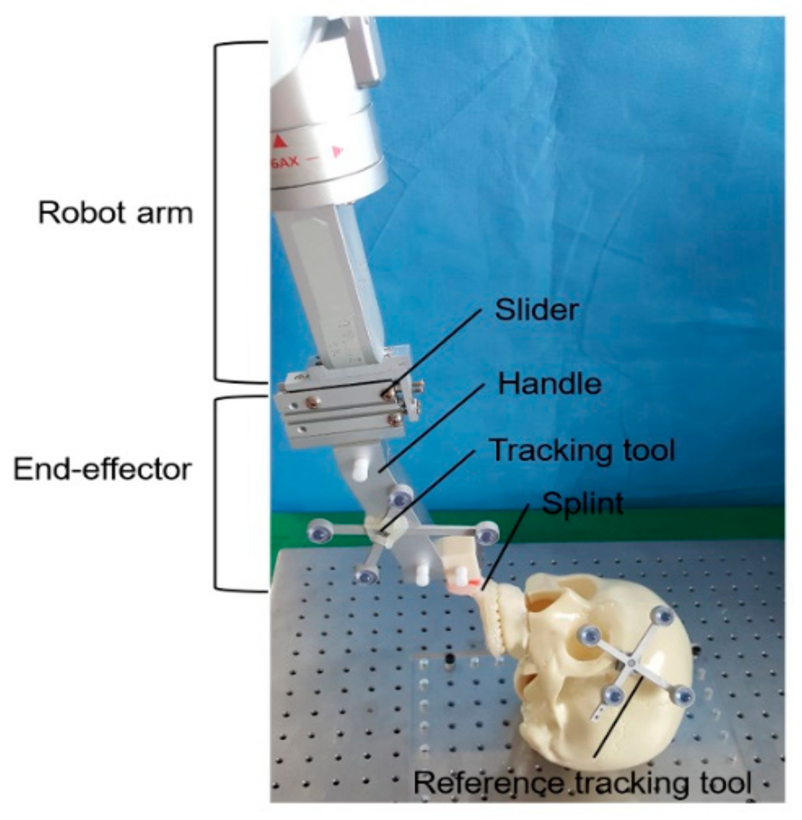
2.1. Robot Arm and Navigation Assisted Orthognathic Vsurgical System

The robot arm and navigation assisted orthognathic surgical system consists of a robot arm with six degrees of freedom (Cyborg-Lab, Suwon, Korea), an image-guided navigation system, including an optical tracking camera and tracking tools, a display, and a computer [21]. The robot arm is controlled by the computer via the robot motion controller provided from the manufacturer (Precise Automation, Fremont, CA, USA), and the repeatability and maximum payload of the robotic system are ± 0.15 mm and 5 kg, respectively. An end-effector of the robot arm was designed to reflect the surgical procedures of maxillary repositioning after Le Fort I osteotomy (Figure 1). The end-effector has a single-axis slider that can translate the maxillary segment upward and downward. Sliding the maxillary segment upward through the vertical axis can enable the surgeon to identify the bone interference and sliding maxillary segment downward can provide enough space to remove any bone interference using a rotary instrument or rongeur. The slider and occlusal splint are connected by a handle that has a tracking tool on its surface, and the slider, handle, and occlusal splint can be easily separated using pin-hole connections. During the surgery, the maxilla can be connected to the robot arm using a splint.
Surgical navigation is performed using an optical tracking system (OTS) (Polaris Spectra, Northern Digital Inc., Waterloo, ON, Canada). The OTS simultaneously tracks the tracking tools which are attached on the end-effector of the robot arm and the patient’s head (the reference tracking tool). Because the end-effector, occlusal splint, and maxillary segment form one rigid body during surgery, the maxillary segment also can be tracked based on the spatial relationship between the end-effector and the maxillary segment. The planned and current maxillary positions can be visualized in axial, sagittal, and coronal planes, and the deviations at five dental landmarks, including the midpoint of the incisal edge of both central incisors, both upper canines, and the mesio-buccal cusp of both upper first molars, can also be provided in real time [21].

2.2. Workflow

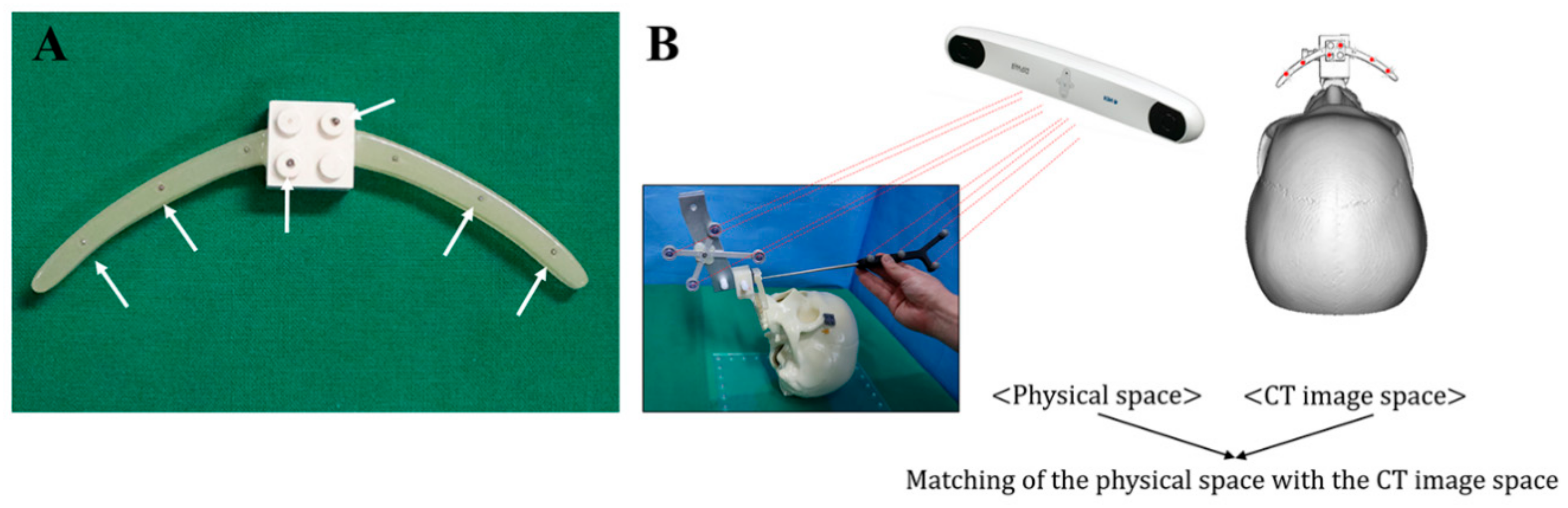
2.2.1. Preoperative Phase

First, the occlusal splint for upper teeth was fabricated using acrylic resin and was attached to the upper teeth before computed tomography (CT) scan. Using the registration body which was connected to the splint, the positions from physical space are related to the location of the CT data [22,23] (Figure 2).
After CT scan (SOMATOM Sensation 10; Siemens, Erlangen, Germany) under 120 kVp and 80 mAs, virtual 3D skull model was constructed and a Le Fort I osteotomy was conducted on the virtual skull model using Mimics 19.0 (Materialise, Leuven, Belgium). To overcome the inaccuracy of CT images due to the slice thickness and artifact and improve the image quality of teeth and teeth-bearing area, maxillary dentition optical scan data was obtained using a 3D scanner (Identica Blue, Medit, Seoul, Korea) and registered with a 3D skull model generated from the CT. First, the virtually osteotomized maxilla after Le Fort I osteotomy was exported in stereolithography interface format (STL) files. The osteotomized maxilla and optical scan data of the maxillary dentition were imported into the inspection program (GOM Inspect; GOM mbH, Braunschiweig, Germany) and set as the norminal data and actual data, respectively. For better registration, the registration process consists of two alignments. The initial alignment is performed automatically, and the main alignment is achieved using the local best-fit method. In the local best-fit method, the palatal and buccal surfaces in the scan data are selected and used as the reference surfaces. The aligned scan data was exported in STL and imported to the simulation program. To determine the accuracy of the registration, the contour of the aligned scan data was compared with the contour of the dentition in CT images on the axial, coronal, and sagittal planes. The registration process was finished after merging the osteotomized maxilla and aligned scan data. Using the simulation program, the osteotomized maxilla is moved to the target position according to the surgical plan.
To match the physical space with the CT image space, registration was performed using the registration body preoperatively (Figure 2B). The physical positions of the fiducial markers on the registration body related to the tracking tool on the end-effector were measured using a wireless tracking tool tip (Northern Digital Inc.). They were registered with their corresponding fiducial markers on the 3D CT images. The relative position between the registration body and tracking tool on the end-effector is always the same and thus can be used for other experiments without measuring the physical positions of the fiducial markers.

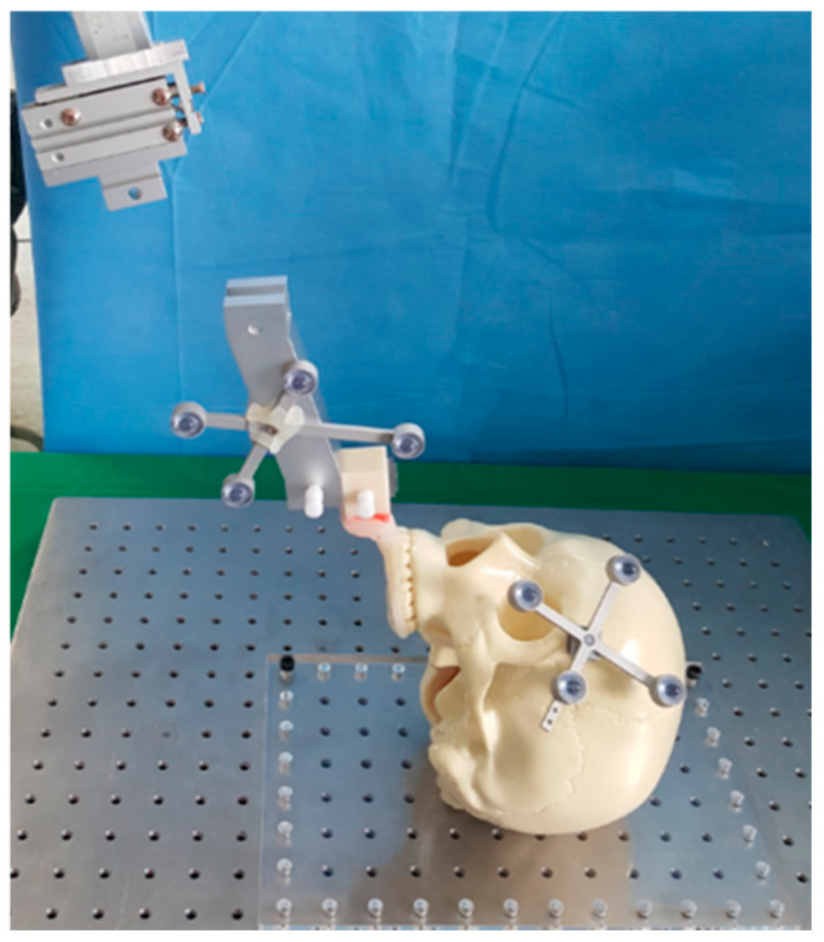
2.2.2. Intraoperative Phase

The first step of the intraoperative procedures is recording the tracking tool position on the end-effector in physical space (Figure 3). Using the position of the tracking tool on the end-effector, we registered the preoperative maxillary position, and the end-effector is subsequently separated from the occlusal splint-maxilla complex subsequently. After a Le Fort I osteotomy is performed by a hand held saw, the end-effector is joined to the distal end of the robot arm (Figure 4). Because the spatial relationship between the end-effector and maxilla is fixed, the position of the maxilla can be estimated and visualized on the display based on the position of the end-effector without joining of the maxillary segment to the end-effector. While the 3D movements of the end-effector are tracked using navigation system, the end-effector can reach the planed position using the robot motion controller. When the maxilla on the display reaches its target position, the actual osteotomized maxilla-splint complex is joined to the end-effector. When the bone interference between the osteotomized maxilla and the upper maxilla above the osteotomy line prevent the joining of the osteotomized maxilla-splint complex and the end effector, it can be accomplished by moving the slider downward (Figure 5A). After identification and removal of bone interference is performed with up and down sliding movement of the slider, we can check and confirm that the maxilla is repositioned in its planned position using the navigation (Figure 5B,C). The deviations between the target position and actual position are recorded on the X-, Y-, and Z-axes at the five dental landmarks.

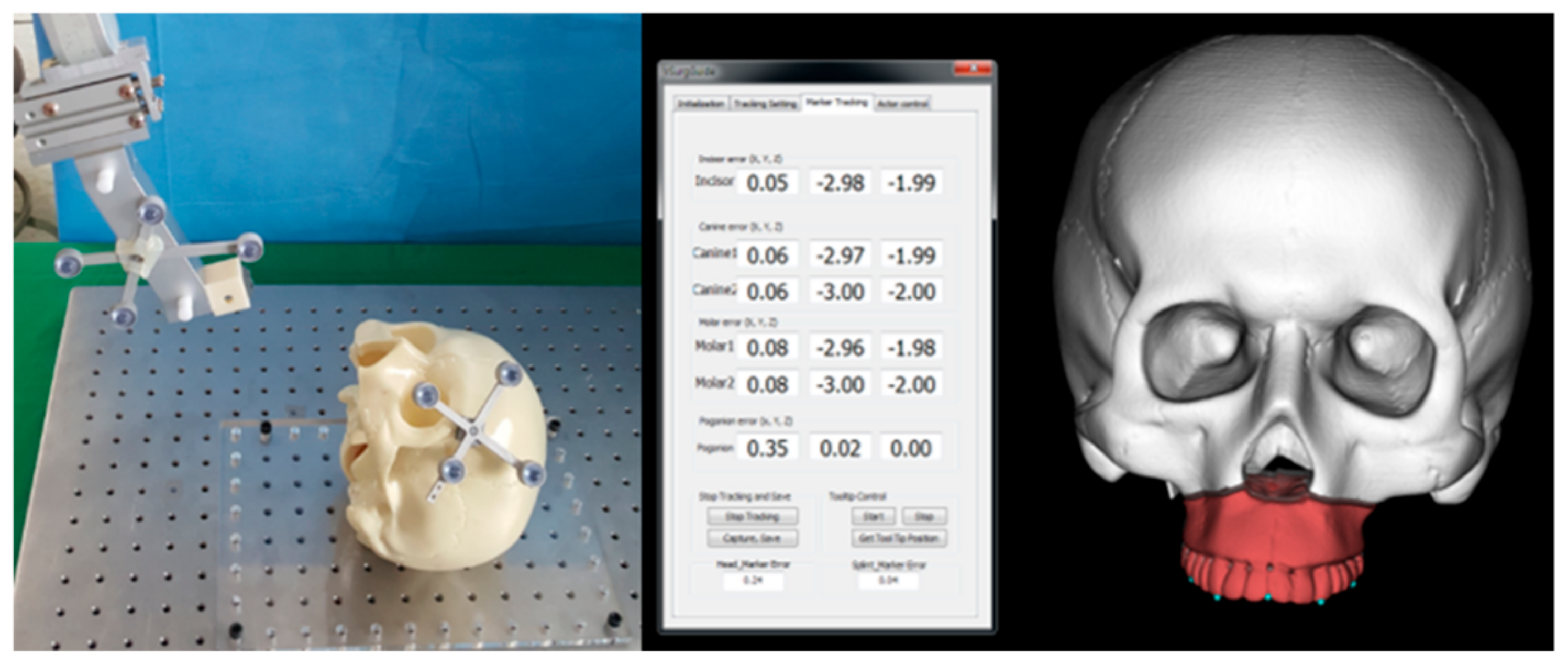
2.3. Accuracy Measurement

To quantify the maxillary repositioning accuracy, the absolute deviations between the planned and achieved positions of the five dental landmarks (the midpoint of the incisal edge of both central incisors, both upper canines, and the mesio-buccal cusp of both upper first molars) were evaluated and the root mean square deviation (RMSD) between the planned and achieved positions was calculated:
RMSD = 1 n i = 1 n x p l a n n e d , i x a c h i v e d , i 2 + y p l a n n e d , i y a c h i v e d , i 2 + z p l a n n e d , i z a c h i v e d , i 2
where x, y, and z denote the coordinates of the planned and achieved positions of the landmarks, and n refers to the total number of landmarks in each assessment.
To compare the maxillary repositioning accuracy between the anterior and posterior regions of the maxilla, the Wilcoxon signed-rank test was performed using the SPSS version 23.0 (SPSS Inc., Chicago, IL, USA). As the accuracy of the posterior maxilla, the average value of accuracy at both upper 1st molars were applied. Statistical significance was set at P < 0.05.

3. Results

3.1. Handling of the Robot Arm and Navigation Assisted Orthognathic Surgical System

To assess the handling and maxillary repositioning accuracy of the robot arm and navigation assisted orthognathic surgical system, 10 experiments were conducted using full skull phantom models (Sawbones; Pacific Research Laboratories Inc., Vashon, WA, USA). The surgical plans implemented in this study included the commonly used surgical plans such as antero-posterior reposition, midline correction, canting correction, and impaction of posterior maxilla (Table 1). Since the accuracy was evaluated after a series of procedures including Le Fort I osteotomy, recognition and removal of bone interference and repositioning of maxillary bone segment, the accuracy evaluation was performed once for each experiment. For all experiments, the end-effector could reach its planned position based on the spatial relationship between the maxilla and the end-effector. Using the end-effector’s sliding movement, the maxillary segment-splint complex was joined to the end-effector of the robot arm even though bone interference was present between the maxillary segment and the upper maxilla. With the up and down sliding movement of the maxillary segment, the bone interference could be identified and removed until the end-effector’s slider reached its initial position. After complete removal of the bone interference, it was confirmed using the navigation system that the maxillary segment was in its target position.

3.2. Accuracy Evaluation

Data of the 10 experiments were described in Table 2. The mean absolute deviation between the planned and achieved positions for upper incisor point was 0.10 ± 0.15 mm in the medio-lateral direction, 0.05 ± 0.07 mm in the antero-posterior direction, and 0.12 ± 0.15 mm in the supero-inferior direction. For right and left upper 1st molars, mean absolute deviations were 0.09 ± 0.10 mm and 0.09 ± 0.10 mm in the medio-lateral direction, 0.10 ± 0.11 mm and 0.09 ± 0.12 mm in the antero-posterior direction, and 0.06 ± 0.04 mm and 0.10 ± 0.11 mm in the supero-inferior direction, respectively. The mean RMSD between the planned and achieved positions for five dental landmarks was 0.18 ± 0.16 mm, and the maximum and minimum RMSDs were 0.54 mm (in the experiment #1) and 0.05 mm (in the experiment #10) (Table 3). With respect to the maxillary repositioning accuracy between the anterior and posterior maxilla, there were no statistically significant differences in the absolute deviations for medio-lateral (P = 0.513), antero-posterior (P = 0.058), and supero-inferior (P = 0.959) directions between the anterior and posterior landmarks.

4. Discussion

With the rapid development of digital technology, various innovative surgical aids for more accurate surgery, including surgical guides, patient-specific plates, and surgical navigation, have been developed and applied. Surgical navigation provides a 3D anatomical position through the application of an indicator with a tracking device, and can also track positional changes of anatomical structures in real time during surgery. In the field of maxillofacial surgery, including orthognathic surgery, the movement of bone segment can be tracked during the operation, and it can be confirmed whether the bone segment is located as planned [7,22,23,24,25]. Chapuis, et al. [25] used intraoperative navigation for the final fixation of the maxilla after intermediary fixation using an intermediate splint. In the study by Chang, et al. [24], maxillary repositioning was performed using navigation with 3D printed positioning guides. Lee, et al. [23] developed an image-guided orthognathic surgical system for repositioning the maxillomandibular complex. However, stabilization and fixation of the movable bone segment while holding the bone segment in the target position is challenging in navigation assisted orthognathic surgery [7,26,27]. Although various temporary support of the mobilized maxillary segment can be used, drilling on an unstable maxillary segment and the unsuitability of the plate bending may influence the repositioning accuracy. To overcome the difficulties in stabilization and fixation of the maxilla, a surgical system that combines the surgical navigation and the robot arm has been proposed [21,28,29,30]. The robot arm can hold the osteotomized maxilla stable for a long time and minor changes of the maxilla can be monitored using the navigation.
Since the Kwoh, et al. [31] introduced the first robotic surgical system that was used for orientation of a needle for brain biopsy, the use of robotic assistants is expanding into various surgical fields due to the distinctive advantages, such as magnified visualization, bimanual operation with robot arms, minimal invasiveness, and lack of tremor. In orthognathic surgery, there also have been efforts to introduce robotic technology into the operation field. Burgner, et al. [28] developed a prototype end-effector for Le Fort I osteotomy and registration methods and presented a system for robot assisted orthognathic surgery. In their system, the preoperative planning of the surgical procedure, such as the acquisition of the initial and target position of the maxilla, was achieved using a mechanical articulator, and then the robotic system acquired the relative transformation between the initial and target positions. After intraoperative registration of the initial position, the maxilla was moved to the target position using the transformation. Vieira, et al. [29] assessed the stability and usability of light-weight robot to hold the maxillary segment in the target position during the drilling and fastening of the maxilla. In the recent study by Wang, et al. [30], a robotic system for orthognathic surgery that consisted of virtual surgery, surgical navigation and a robot-arm was proposed, and its reliability was analyzed according to the preliminary experiments to measure the distance between the fiducial markers after repositioning the maxilla. Despite the fact the several robot-assisted surgical systems for orthognathic surgery has been proposed, the clinical application of the robot-assisted surgical system has not been reported, and this system still remains in an experimental stage [20]. There are several limitations have to overcome for broader application of the robot assistant to orthognathic surgery. One of the limitations of current robotic assistants is a lack of tactile perception and haptic feedback. Thus, the proper resistance is not provided to the surgeon, which can cause undesirable damage when performing the osteotomy or moving bone segments. In addition, operation time may increase due to the complicated preoperative preparation, such as docking of the robot, adequate positioning of the robot and patient, and preoperative registration. A lack of specially designed surgical instrument for orthognathic surgery is another limitation.
In robot-assisted orthognathic surgery, it may be ideal that the mobilized bone segment is moved to the target position using an automatic robotic assistant [21]. However, autonomous bone repositioning may be accomplished only when the bone interference between the bone segments is completely removed. Although surgeons can identify the location and amount of bone interference using 3D simulation surgery, it is difficult to immediately remove bone interference due to the different osteotomy lines and unpredictable pterygomaxillary separation compared to virtual simulation surgery. Thus, repeatedly repositioning the maxilla to the target position for the identification of bone interference is inevitable, but it is time-consuming even though when repeatedly repositioning the maxilla can be achieved automatically. Increasing the working speed of the robot arm may be directly related to safety due to unexpected soft tissue injury including neurovascular bundles. Furthermore, the location and amount of bone interference may also vary depending on the path of reaching the maxilla to the target position. In addition, since tactile sensation is not provided to surgeon, it is difficult to precisely identify bone interference using only the eyes during autonomous bone repositioning. Finally, the autonomous execution of robot assistants requires more complex technology due to the registration between the robot space and the physical space. For these reasons, in the system developed in this study, the maxilla was moved to the target position using the robot arm’s hands-on mode via image-guided navigation. The bone interference, that occurred during the repositioning of the maxilla, was identified and removed easily using the specialized end-effector with a single-axis slider and the rotary instrument. Specifically, bone interference was identified easily with the sliding up of the maxilla, and sufficient work space for removal of the bone interference using the rotary instrument was obtained with the sliding down of the maxilla. After the complete removal of bone interference, the slider reached its initial position, and it was confirmed based on the navigation whether the maxilla also reached its target position.
There were several reports studied on the maxillary repositioning accuracy in navigation assisted orthognathic surgery. In the study by Chapuis, et al. [25], the mean deviation between the planned and postoperative maxillary position was 1.1 ± 0.9 mm after maxillary repositioning using OTS. Lee, et al. [23] reported that RMSD between the preoperative planning and intraoperative guidance was 1.16 mm immediately after repositioning of the maxillomandibular complex using OTS and image-guided navigation. For navigation using the electromagnetic (EM) tracking, Berger, et al. [32] reported that the mean absolute deviation ascertained by EM tracking was 0.9 mm after maxillary repositioning using EM navigation in phantom skulls. In a clinical pilot study using EM tracking by the same study group, the mean absolute deviations of the maxilla were 1.0 mm on the x-axis, 0.9 mm on the y-axis, and 1.2 mm on the z-axis in the intraoperative navigation, and the RMSD was 2.1 mm [26]. Unlike navigation-assisted orthognathic surgery, where a number of surgical accuracy assessments have been reported, there are few studies on surgical accuracy for robot and navigation assisted surgery. In the present study, to reproduce the actual surgical procedures, we performed virtual surgery according to the four different surgical plans and performed maxillary orthognathic surgery including the removal of bone interference and repositioning of the maxilla using the robot arm and navigation assisted orthognathic surgical system. Compared to navigation assisted surgery, we found improved accuracy in this study where the mean RMSD was less than 0.2 mm. Although the first two experiments exhibited relative greater RMSD values (0.5 mm in the first experiment and 0.4 mm in the second experiment), the last eight experiments showed more improved accuracy. In contrast to navigation assisted orthognathic surgery, where the repositioning and holding of the maxilla is dependent on the operator’s hand, we could fine-tune and maintain the maxillary position using the robot arm and navigation system.
In addition to the repositioning accuracy, the orthognathic surgical system using the robot arm and navigation system has several advantages. In traditional or CAD/CAM device based orthognathic surgery, surgeons can guide the bone segment only to a predetermined target position. However, intraoperative changes in surgical plans according to the soft tissue response are desirable because preoperative soft tissue prediction can be in accurate. In addition, there may be inadequate preoperative evaluation, misdiagnosis, and inappropriate surgical planning. Using robot arm and navigation system, the surgical plan can be easily modified during surgery. Direct transfer of the surgical plan is another advantage of this system. In contrast to traditional methods using intermediate splints, repositioning errors caused by the mandibular autorotation or the patient’s condylar condition can be prevented.
Despite the great potentials of robotic assistants for orthognathic surgery, clinical applications of the robot require further technological advances in several aspects including safety and convenience [20,21]. Excessive force of robot can damage the bone segments and surrounding bone such as the maxillary wall above the osteotomy line. Adjacent intraoral or perioral soft tissue including neurovascular bundles also can be damaged from the uncontrolled movement of the robot. Therefore, advanced safety equipment including force-torque sensor is essential to detect dangerous motion of the robot arm and to prevent related injuries. In addition, development of specialized software is necessary to provide surgeons with more convenient and efficient surgical environment.

5. Conclusions

In this study, we used the robot arm via hands-on mode and the image-guided navigation for maxillary orthognathic surgery. Our results suggest that the developed system would be helpful to identify and remove bone interferences and reposition the bone segments with improved accuracy and safety. Though further technological advances are necessary for clinical applications, the principle and system may provide important information for the development of more advanced and automated robot system for orthognathic surgery in future.

Author Contributions

Conceptualization, S.J.H.; Data curation, J.J.H.; Formal analysis, J.J.H.; Investigation, J.J.H.; Methodology, J.J.H., S.-Y.W., W.-J.Y. and S.J.H.; Resources, J.J.H., S.-Y.W., W.-J.Y. and S.J.H.; Software, S.-Y.W.; Supervision, W.-J.Y. and S.J.H.; Writing–original draft, J.J.H.; Writing–review & editing, W.-J.Y. and S.J.H. All authors have read and agreed to the published version of the manuscript.

Funding

This study was supported by a grant (HI13C1491) from the Korea Health Technology R&D Project, Ministry of Health and Welfare, Republic of Korea.

Conflicts of Interest

The authors have no financial interest to declare in relation to the content of this article.

References

  1. Ellis, E. Bimaxillary surgery using an intermediate splint to position the maxilla. J. Oral Maxillofac. Surg. 1999, 57, 53–56. [Google Scholar] [CrossRef]
  2. Ellis, E. Accuracy of model surgery: Evaluation of an old technique and introduction of a new one. J. Oral Maxillofac. Surg. 1990, 48, 1161–1167. [Google Scholar] [CrossRef]
  3. Olszewski, R.; Reychler, H. Limitations of orthognathic model surgery: Theoretical and practical implications. Rev. Stomatol. Chir. Maxillofac. 2004, 105, 165–169. [Google Scholar] [CrossRef]
  4. Gateno, J.; Xia, J.; Teichgraeber, J.F.; Rosen, A.; Hultgren, B.; Vadnais, T. The precision of computer-generated surgical splints. J. Oral Maxillofac. Surg. 2003, 61, 814–817. [Google Scholar] [CrossRef]
  5. Swennen, G.R.; Mollemans, W.; Schutyser, F. Three-dimensional treatment planning of orthognathic surgery in the era of virtual imaging. J. Oral Maxillofac. Surg. 2009, 67, 2080–2092. [Google Scholar] [CrossRef]
  6. Zinser, M.J.; Sailer, H.F.; Ritter, L.; Braumann, B.; Maegele, M.; Zoller, J.E. A paradigm shift in orthognathic surgery? A comparison of navigation, computer-aided designed/computer-aided manufactured splints, and “classic” intermaxillary splints to surgical transfer of virtual orthognathic planning. J. Oral Maxillofac. Surg. 2013, 71, e1–e21. [Google Scholar] [CrossRef]
  7. Van den Bempt, M.; Liebregts, J.; Maal, T.; Berge, S.; Xi, T. Toward a higher accuracy in orthognathic surgery by using intraoperative computer navigation, 3D surgical guides, and/or customized osteosynthesis plates: A systematic review. J. Cranio Maxillofac. Surg. 2018, 46, 2108–2119. [Google Scholar] [CrossRef]
  8. Gander, T.; Bredell, M.; Eliades, T.; Rucker, M.; Essig, H. Splintless orthognathic surgery: A novel technique using patient-specific implants (PSI). J. Cranio Maxillofac. Surg. 2015, 43, 319–322. [Google Scholar] [CrossRef]
  9. Han, J.J.; Yang, H.J.; Hwang, S.J. Repositioning of the Maxillomandibular Complex Using Maxillary Template Adjusted Only by Maxillary Surface Configuration Without an Intermediate Splint in Orthognathic Surgery. J. Craniofac. Surg. 2016, 27, 1550–1553. [Google Scholar] [CrossRef]
  10. Mazzoni, S.; Bianchi, A.; Schiariti, G.; Badiali, G.; Marchetti, C. Computer-aided design and computer-aided manufacturing cutting guides and customized titanium plates are useful in upper maxilla waferless repositioning. J. Oral Maxillofac. Surg. 2015, 73, 701–707. [Google Scholar] [CrossRef]
  11. Suojanen, J.; Leikola, J.; Stoor, P. The use of patient-specific implants in orthognathic surgery: A series of 32 maxillary osteotomy patients. J. Cranio Maxillofac. Surg. 2016, 44, 1913–1916. [Google Scholar] [CrossRef] [Green Version]
  12. Heufelder, M.; Wilde, F.; Pietzka, S.; Mascha, F.; Winter, K.; Schramm, A.; Rana, M. Clinical accuracy of waferless maxillary positioning using customized surgical guides and patient specific osteosynthesis in bimaxillary orthognathic surgery. J. Cranio Maxillofac. Surg. 2017, 45, 1578–1585. [Google Scholar] [CrossRef]
  13. Jakopec, M.; Harris, S.J.; Rodriguez y Baena, F.; Gomes, P.; Cobb, J.; Davies, B.L. The first clinical application of a “hands-on” robotic knee surgery system. Comput. Aided Surg. 2001, 6, 329–339. [Google Scholar] [CrossRef]
  14. Varma, T.R.; Eldridge, P. Use of the NeuroMate stereotactic robot in a frameless mode for functional neurosurgery. Int. J. Med. Robot. 2006, 2, 107–113. [Google Scholar] [CrossRef] [PubMed]
  15. Cadiere, G.B.; Himpens, J.; Germay, O.; Izizaw, R.; Degueldre, M.; Vandromme, J.; Capelluto, E.; Bruyns, J. Feasibility of robotic laparoscopic surgery: 146 cases. World J. Surg. 2001, 25, 1467–1477. [Google Scholar] [CrossRef] [PubMed]
  16. Beasley, R.A. Medical Robots: Current Systems and Research Directions. J. Robot. 2012, 401613. [Google Scholar] [CrossRef]
  17. Genden, E.M.; Desai, S.; Sung, C.K. Transoral robotic surgery for the management of head and neck cancer: A preliminary experience. Head Neck 2009, 31, 283–289. [Google Scholar] [CrossRef]
  18. Lin, L.; Shi, Y.; Tan, A.; Bogari, M.; Zhu, M.; Xin, Y.; Xu, H.; Zhang, Y.; Xie, L.; Chai, G. Mandibular angle split osteotomy based on a novel augmented reality navigation using specialized robot-assisted arms--A feasibility study. J. Cranio Maxillofac. Surg. 2016, 44, 215–223. [Google Scholar] [CrossRef]
  19. Pugin, F.; Bucher, P.; Morel, P. History of robotic surgery: From AESOP(R) and ZEUS(R) to da Vinci(R). J. Visc. Surg. 2011, 148, e3–e8. [Google Scholar] [CrossRef]
  20. Liu, H.H.; Li, L.J.; Shi, B.; Xu, C.W.; Luo, E. Robotic surgical systems in maxillofacial surgery: A review. Int. J. Oral Sci. 2017, 9, 63–73. [Google Scholar] [CrossRef]
  21. Woo, S.Y.; Lee, S.J.; Yoo, J.Y.; Han, J.J.; Hwang, S.J.; Huh, K.H.; Lee, S.S.; Heo, M.S.; Choi, S.C.; Yi, W.J. Autonomous bone reposition around anatomical landmark for robot-assisted orthognathic surgery. J. Cranio Maxillofac. Surg. 2017, 45, 1980–1988. [Google Scholar] [CrossRef] [PubMed]
  22. Kim, D.S.; Woo, S.Y.; Yang, H.J.; Huh, K.H.; Lee, S.S.; Heo, M.S.; Choi, S.C.; Hwang, S.J.; Yi, W.J. An integrated orthognathic surgery system for virtual planning and image-guided transfer without intermediate splint. J. Cranio Maxillofac. Surg. 2014, 42, 2010–2017. [Google Scholar] [CrossRef] [PubMed]
  23. Lee, S.J.; Woo, S.Y.; Huh, K.H.; Lee, S.S.; Heo, M.S.; Choi, S.C.; Han, J.J.; Yang, H.J.; Hwang, S.J.; Yi, W.J. Virtual skeletal complex model- and landmark-guided orthognathic surgery system. J. Cranio Maxillofac. Surg. 2016, 44, 557–568. [Google Scholar] [CrossRef] [PubMed]
  24. Chang, H.W.; Lin, H.H.; Chortrakarnkij, P.; Kim, S.G.; Lo, L.J. Intraoperative navigation for single-splint two-jaw orthognathic surgery: From model to actual surgery. J. Cranio Maxillofac. Surg. 2015, 43, 1119–1126. [Google Scholar] [CrossRef] [PubMed]
  25. Chapuis, J.; Schramm, A.; Pappas, I.; Hallermann, W.; Schwenzer-Zimmerer, K.; Langlotz, F.; Caversaccio, M. A new system for computer-aided preoperative planning and intraoperative navigation during corrective jaw surgery. IEEE Trans. Inf. Technol. Biomed. 2007, 11, 274–287. [Google Scholar] [CrossRef]
  26. Berger, M.; Nova, I.; Kallus, S.; Ristow, O.; Freudlsperger, C.; Eisenmann, U.; Dickhaus, H.; Engel, M.; Hoffmann, J.; Seeberger, R. Can electromagnetic-navigated maxillary positioning replace occlusional splints in orthognathic surgery? A clinical pilot study. J. Cranio Maxillofac. Surg. 2017, 45, 1593–1599. [Google Scholar] [CrossRef]
  27. Li, B.; Zhang, L.; Sun, H.; Shen, S.G.; Wang, X. A new method of surgical navigation for orthognathic surgery: Optical tracking guided free-hand repositioning of the maxillomandibular complex. J. Craniofac. Surg. 2014, 25, 406–411. [Google Scholar] [CrossRef]
  28. Burgner, J.; Toma, M.; Vieira, V.; Eggers, G.; Raczkowsky, J.; Muhling, J.; Marmulla, R.; Worn, H. System for robot assisted orthognathic surgery. Int. J. Comput. Assist. Radiol. Surger. 2007, 2, S419–S421. [Google Scholar]
  29. Vieira, V.M.M.; Kane, G.J.; Ionesco, H.; Raszkowsky, J.; Boesecke, R.; Eggers, G. Light-weight robot stability for orthognathic surgery. Phantom and animal cadavar trials. In Proceedings of the Deutschen Gesellschaft für Computer-und Roboterassistierte Chirurgie, Dusseldorf, Germany, 18–19 November 2010; pp. 99–101. [Google Scholar]
  30. Wang, X.; Song, R.; Liu, X.; Li, Q.; Cheng, T.; Xue, Y. System design for orthognathic aided robot. In Proceedings of the 5th annual IEEE International Conference on Cyber Technology in Automation, Control and Intelligent Systems, Shenyang, China, 6–10 June 2015; pp. 612–617. [Google Scholar]
  31. Kwoh, Y.S.; Hou, J.; Jonckheere, E.A.; Hayati, S. A robot with improved absolute positioning accuracy for CT guided stereotactic brain surgery. IEEE Trans. Biomed. Eng. 1988, 35, 153–160. [Google Scholar] [CrossRef]
  32. Berger, M.; Kallus, S.; Nova, I.; Ristow, O.; Eisenmann, U.; Dickhaus, H.; Kuhle, R.; Hoffmann, J.; Seeberger, R. Approach to intraoperative electromagnetic navigation in orthognathic surgery: A phantom skull based trial. J. Cranio Maxillofac. Surg. 2015, 43, 1731–1736. [Google Scholar] [CrossRef]
Figure 1. End-effector and robot arm.
Applsci 10 01549 g001
Figure 2. Preoperative registration. (A) Registration body including the fiducial markers (arrow). (B) Matching of the physical space with the CT image.
Applsci 10 01549 g002
Figure 3. Intraoperative initial registration.
Applsci 10 01549 g003
Figure 4. Tracking the three-dimensional movements of the end-effector and visualization of the estimated maxillary position on the screen.
Applsci 10 01549 g004
Figure 5. Identification (A) and removal (B) of the bony interference. (C) Final position of the maxilla according to the surgical plan.
Applsci 10 01549 g005
Table 1. The surgical plans implemented in this study.
ExperimentSurgical Plan
#1Advancement by 3 mm and downward by 2 mm
#2Advancement by 3 mm and downward by 2 mm
#3Cant correction by 4 mm (Right, 2 mm upward; Left, 2 mm downward)
#4Cant correction by 4 mm (Right, 2 mm upward; Left, 2 mm downward)
#5Posterior impaction at the upper first molar by 3 mm
#6Posterior impaction at the upper first molar by 3 mm
#7Bodily shift to right side by 3 mm
#8Bodily shift to right side by 3 mm
#9Advancement by 3 mm and downward by 2 mm
#10Cant correction by 4 mm (Right, 2 mm upward; Left, 2 mm downward)
Table 2. Absolute Deviation between the Planned and Achieved Positions for Five Dental Landmarks.
Upper Incisor PointRight Upper CanineLeft Upper CanineRight Upper 1st MolarLeft Upper 1st Molar
Experimentxyzxyzxyzxyzxyz
#10.510.030.410.430.140.310.420.180.140.270.070.120.250.430.39
#20.190.210.360.140.310.160.140.100.340.000.250.130.000.070.13
#30.140.140.220.180.240.150.190.040.180.260.330.030.280.040.07
#40.050.020.040.060.040.010.060.000.020.080.030.080.090.020.04
#50.000.000.000.020.040.020.020.050.010.050.070.040.050.050.01
#60.020.020.050.020.010.050.030.040.090.030.020.070.030.070.13
#70.060.070.030.070.080.020.070.060.050.070.080.030.070.050.06
#80.010.030.020.010.030.000.010.040.010.010.050.030.010.070.05
#90.000.000.050.020.040.070.020.050.050.060.060.090.060.060.07
#100.040.020.010.050.010.010.050.020.020.050.010.010.050.030.03
Mean0.100.050.120.100.090.080.100.060.090.090.100.060.090.090.10
SD0.160.070.150.130.100.100.130.050.100.100.110.040.100.120.11
Data are presented in millimeters. x, medio-lateral direction; y, antero-posterior direction; z, supero-inferior direction; SD, standard deviation.
Table 3. Root Mean Square Deviation between the Planned and Achieved Positions for Five Dental Landmarks.
Experiment#1#2#3#4#5#6#7#8#9#10Mean ± SD
RMSD0.540.350.330.090.060.100.110.060.090.050.18 ± 0.16
Data are presented in millimeters. RMSD, root mean square deviation; SD, standard deviation.

