Article

A Case Study about Biomass Torrefaction on an Industrial Scale: Solutions to Problems Related to Self-Heating, Difficulties in Pelletizing, and Excessive Wear of Production Equipment

by
Leonel J.R. Nunes
1,2,3,4
1
PROMETHEUS, ESA-Escola Superior Agrária, IPVC-Instituto Politécnico de Viana do Castelo, Rua da Escola Industrial e Comercial de Nun’Alvares, 4900-347 Viana do Castelo, Portugal
2
GOVCOPP, DEGEIT-Departamento de Economia, Gestão, Engenharia Industrial e Turismo, Universidade de Aveiro, Campus Universitário de Santiago, 3810-193 Aveiro, Portugal
3
YGE—Yser Green Energy SA, Área de Acolhimento Empresarial de Úl/Loureiro, Lote 17, 3720-075 Loureiro OAZ, Portugal
4
AFS—Advanced Fuel Solutions SA, Área de Acolhimento Empresarial de Úl/Loureiro, Lote 17, 3720-075 Loureiro OAZ, Portugal
Submission received: 10 March 2020 / Revised: 30 March 2020 / Accepted: 2 April 2020 / Published: 7 April 2020
(This article belongs to the Special Issue Biomass Energy and Biomass as a Clean Renewable Fuel)

Abstract

:
The search for different forms of biomass that can be used as an alternative to those more traditional ones has faced numerous difficulties, namely those related to disadvantages that the majority of residual forms present. However, these residual forms of biomass also have advantages, namely the fact that, by being outside the usual biomass supply chains for energy, they are usually much cheaper, and therefore contribute to a significant reduction in production costs. To improve the less-favorable properties of these biomasses, thermochemical conversion technologies, namely torrefaction, are presented as a way to improve the combustibility of these materials. However, it is a technology that has not yet demonstrated its full potential, mainly due to difficulties in the process of scale-up and process control. In this article it is intended to present the experience obtained over 5 years in the operation of a biomass torrefaction plant with an industrial pilot scale, where all the difficulties encountered and how they were corrected are presented, until it became a fully operational plant. This article, in which a real case study is analyzed, presents in a descriptive way all the work done during the time from when the plant started up and during the commissioning period until the state of continuous operation had been reached.

1. Introduction

The incessant search for new forms of energy that can replace the use of non-renewable sources of fossil origin by renewable sources led to an increase in the number of technical studies and fundamental research, mainly related to the possibility of reproducing natural processes, which are in the origin of different forms of fossil energy, such as coal, oil or natural gas, since the entire global energy system is based on the conversion and use of these fossil forms [1,2,3,4]. Thus, guidelines for many research and development projects related to energy conversion have been launched, among which biomass is already playing a very important role, as it is the form of energy that makes it possible to meet the global energy needs, based on liquid and gaseous fuels for mobility, and solid fuels for the production of electricity, usually static, and for the production of industrial thermal energy [5,6,7,8].
Biomass also makes it possible to compensate the intermittency associated with the production of energy through renewable sources, namely the forms that are associated with meteorological elements, such as solar, wind or water, because, depending directly on the weather conditions these may or may not allow energy production. Therefore, it is necessary to have a form of back-up production that, if required, can ensure the continuity of the energy supply service [4,9,10,11].
However, the disadvantages associated with the use of biomass as a primary source of energy are already well documented, as it is the most widely used form of renewable energy worldwide, and is also the one that mankind has been using for the longest time [12,13,14,15]. In fact, biomass can be considered as the first source of energy that mankind learned to master, using combustion, which was most likely discovered accidentally, but which humans quickly learned to replicate whenever necessary [16,17,18]. Nevertheless, despite disadvantages that biomass presents, such as low density, high moisture content, low calorific value, high dispersion and all the problems associated with logistics and handling, it still offers the possibility of serving as a reserve of energy, always being available and ready to be used when necessary, and it can therefore be considered a form of energy storage [19,20,21,22,23].
This is the main characteristic that has aroused so much recent interest in the potential for using biomass as an energy source. That associated with the fact that it can be converted into different forms made the interest even greater. In other words, it was soon understood that it was possible to obtain from biomass a renewable equivalent for any element of the fossil fuel family. For example, gasoline can be replaced by ethanol, diesel by biodiesel, mineral coal by charcoal or by torrefied biomass, natural gas by biogas, among others [24,25,26].
A space for the development of new forms of renewable energy has been emerging, leaving the path open for next step, which is the industrialization of processes, since in reality, despite the potential that exists for the use of different conversion technologies and the valorization of the different forms of biomass, in fact, very little has been achieved on a scale that can be considered industrial and that has real impact as a contribution to the decarbonization of the economy and energy production [27,28,29,30,31].
While on the one hand conversion technologies such as fermentation and anaerobic digestion are already capable of operating successfully at scales considered as being of industrial sizes, on the other hand technologies such as torrefaction, pyrolysis and gasification are not yet capable of presenting convincing results, and do not yet guarantee the capacity of continuous, homogeneous and permanent supply that energy systems need [32,33,34]. The main reason identified for this is the difficulty in successfully and efficiently progressing from laboratory scale, or from a small industrial pilot, to a productive industrial scale, since many problems still cannot be observed, modeled or even understood yet, as they only occur precisely when processes occur at larger scales [29,35,36,37].
For this reason, many projects, mainly associated with the production of torrefied biomass, which were initially considered as disruptive, become profound failures, as demonstrated by the various news reports on the internet. These reports have presented several examples of biomass torrefaction companies that had to close due to technical difficulties [29,35,38]. However, other cases, which started at smaller scales, and which kept the processes running for extended periods of time, have managed to evolve. This is because it was possible to foresee certain problems, namely the difficulty in pelletizing torrefied material when it exceeded a determined torrefaction temperature, or residence time of the material inside the reactor. The latter, in addition to the difficulty in the pelletizing process, was also responsible for the abnormal wear of some components in the pelletizing equipment. Perhaps the most serious problem was the phenomenon of self-heating or self-ignition, which causes safety problems during the transport and storage of torrefied materials [34,39,40].
This article describes and presents the solutions found during the 5-year period of continuous operation of a torrefied biomass pellet production unit, installed in Portugal, on a pilot-industrial scale, with the main objective of acquiring knowledge on the torrefaction process and on torrefied products, with a view to the possibility of moving to an industrial scale unit in the short term. This article, which should be understood as a case study analysis, will focus mainly on describing the processes in which problems and bottlenecks such as those listed above are expected to occur, in order to later present a possible solution, which has then been implemented and proven to be successful. Today, this article can be considered the corollary of a research-action methodology, fully implemented over 5 years, beginning from the awareness of problems to their understanding and resolution.

2. Materials and Methods

2.1. Framework

The process began in 2012 with the creation of the company YGE—Yser Green Energy SA, with headquarters in Oliveira de Azeméis (Northern Portugal). Once this company had been created, biomass torrefaction equipment was acquired supported by the research carried out on available technologies, which at the time were already known and widely discussed, and also on a deep analysis of the market expectations for new products, and how it could offer an alternative to others, including renewable forms already in use, such as biomass pellets, but mainly as an alternative to coal for the production of thermal and electric energy.
Starting with the analysis of the technologies available at the time, it was clear that several were advertised as being able to fulfill a set of assumptions concerning production capacity, but also quality criteria and product characteristics. To measure these capacities, several international manufacturers were visited, at a time when the United States presented itself as the birthplace of a group of companies that presented turnkey solutions to the market. These had reduced production capacities, fitted into pilot-industrial scale, which was undoubtedly a fundamental requirement, in order to be able to study all the conditions associated with production on an industrial scale and in a continuous process. This contrasts with the laboratorial scale, from where it is possible to check the characteristics of the products, but where it is difficult, or even impossible, to check process conditions.
After the comparative analysis between the different technologies available in the market, it was decided to use a rotary drum torrefaction reactor, in this case with an indirect heating biomass fueled system supplied by the North American company ECPI—Earth Care Products Inc. (Independence, KS, USA). The equipment was installed during 2013, with a theoretical production capacity of 720 kg/h of torrefied biomass. This unit did not initially include the densification unit for the torrefied material. However, still during the installation phase, pelletizing equipment from the Italian company La Meccanica was added, with a production capacity of 1200 kg/h. The choice for this equipment, with a production capacity greater than that of the torrefaction equipment, raised a problem, since there was a decrease in the pelletizing capacity due to the fluctuations in the properties of the torrefied material, as was later verified as worthy of special attention. Figure 1 shows an aerial view of the YGE production plant in full operation.
However, even before the work on the installation of the equipment at the YGE industrial unit was completed, research work began, mainly related to the pelletization of torrefied material. This work was carried out with torrefied material, composed by woodchips from Picea spp., produced in the United States in a demonstration unit owned by the manufacturer and similar to that acquired and being installed in Portugal. The pelletization tests were carried out during 2012 and 2013 in another biomass pellets production plant located in North Portugal as well, with and without additives, and with different granulometries, in order to start the development of a torrefaction biomass pelletization procedure.
In these first pelletizing tests, samples of torrefied biomass, consisting of material with a particle size smaller than 16 mm, were received in bags, and subsequently mixed and homogenized. Then, the moisture content of the material was measured in order to quantify the water that needed to be added during the pelletization process. In these tests, a hammer mill was used for grinding, associated with a pneumatic conveying system that transported the material after grinding to a silo, which served as intermediate storage to supply the pelletizer. Figure 2 shows the pneumatic conveying system and the hammer mill. At the bottom of the hammer mill is the connection that leads to the intermediate storage silo and the connection to the pelletizer.
Figure 3 shows the sequence of events in the production of pellets with the different mixtures made. In these mixtures, moisture content, granulometry and use, or not, of additives were varied. In the pelletizing tests, equipment from the German manufacturer Muench-Edelstahl was used, with a theoretical production capacity of 1200 kg/h.
Figure 4 shows an example of the pelletized material. As can be seen, pellets of torrefied biomass with a shiny metallic appearance, with high density, above 750 kg/m3, and a durability greater than 99%, were obtained. However, it was found that, during the period of testing, the effort required for pelletizing was very intense, as verified by the amperage of the equipment, which was always above the expected level during the test, and also proven by the low production index, which never exceeded 150 kg/h.
As verified during the pelletization tests, difficulties immediately arose in the process, which caused great wear in parts of the pelletizer, which had an impact on the roller shells and the die. At the time, while still not understanding the cause of the problems arising, it was immediately understood that it would be necessary to create a line of investigation to develop a procedure that would allow the pelletization of torrefied material without the effort observed during the test, but essentially without the production break that occurred. In a first analysis, it was understood that this difficulty in pelletizing was essentially due to the high degree of torrefaction that the material presented, since the production parameters of this torrefied material were unknown and the production temperature could, therefore, be too high or the residence time too long.

2.2. Process Description
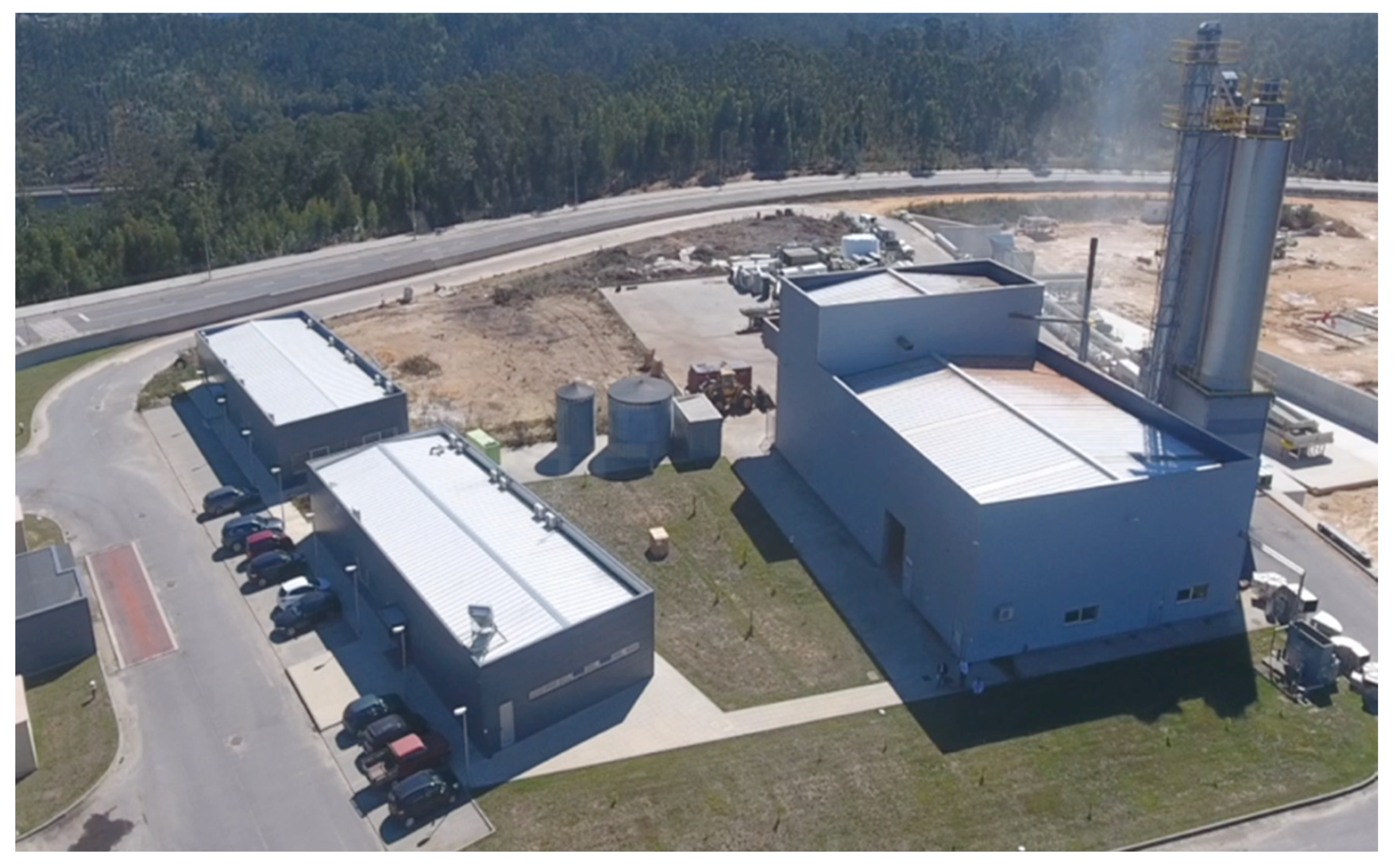
2.2.1. Overview

With the conclusion of the installation and assembly of the equipment, the start-up and commissioning of the torrefaction unit began, in order to identify the weaknesses of the production line. This production line is divided into several parts, considered essential to the correct processing of the raw material.

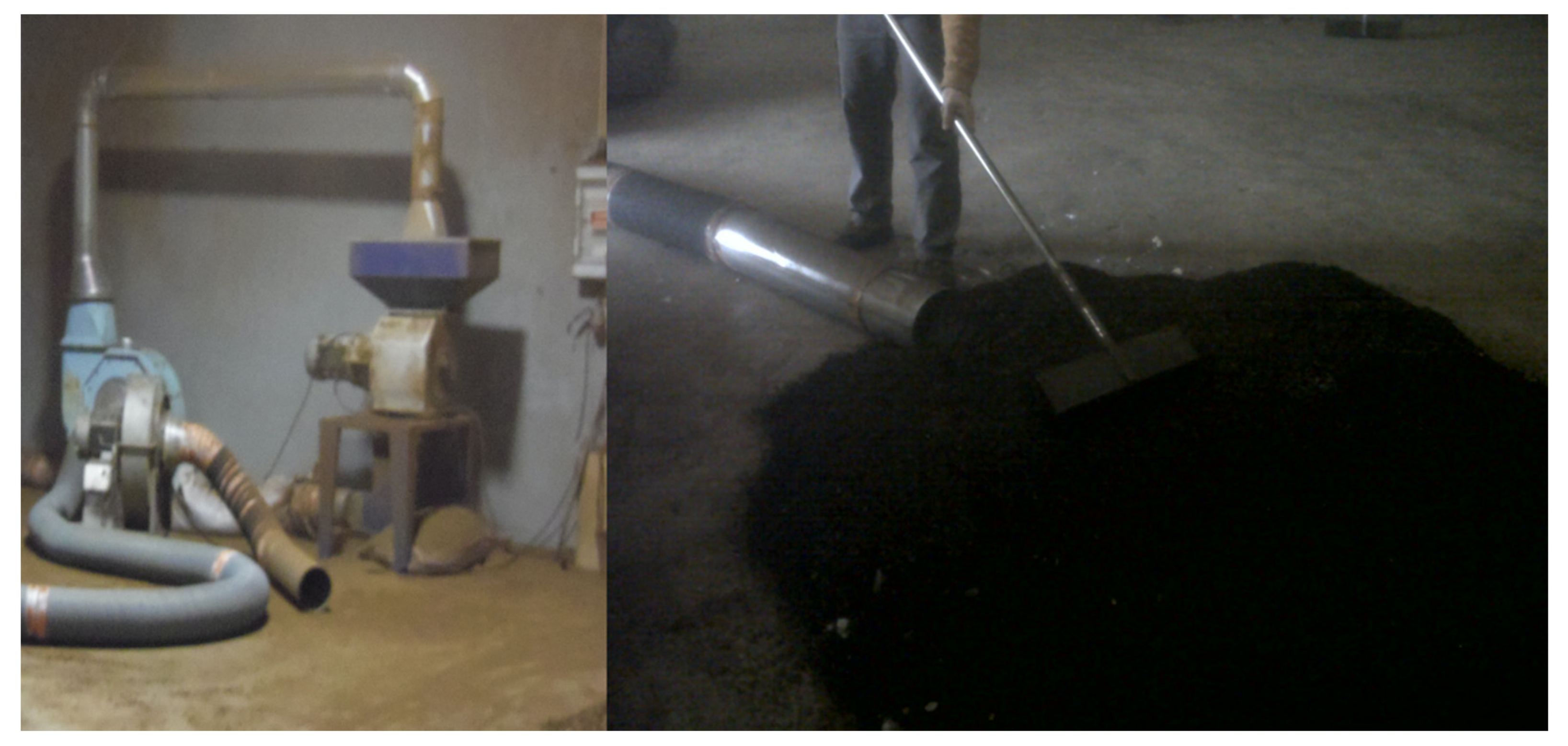
2.2.2. Biomass Shredding Section

Biomass arrives at the production unit in the form of logs which, after weighing and checking moisture, are discharged and stored in the raw materials park. This is an open-air park, not covered, where the trunks are deposited in parallel piles approximately 60 m long and 4 to 5 m high. It is from these piles that the shredding equipment is supplied, in this specific case, an Austrian MUS MAX equipment with a production capacity of 12 t/h. The material, after shredding into the form of chips with a G30 dimension, is placed into a single pile, with a sufficient amount to allow the operation for a continuous period of 48 h. This was intended to avoid any problem associated with the risk of fire caused by the fermentation of the shredded material.

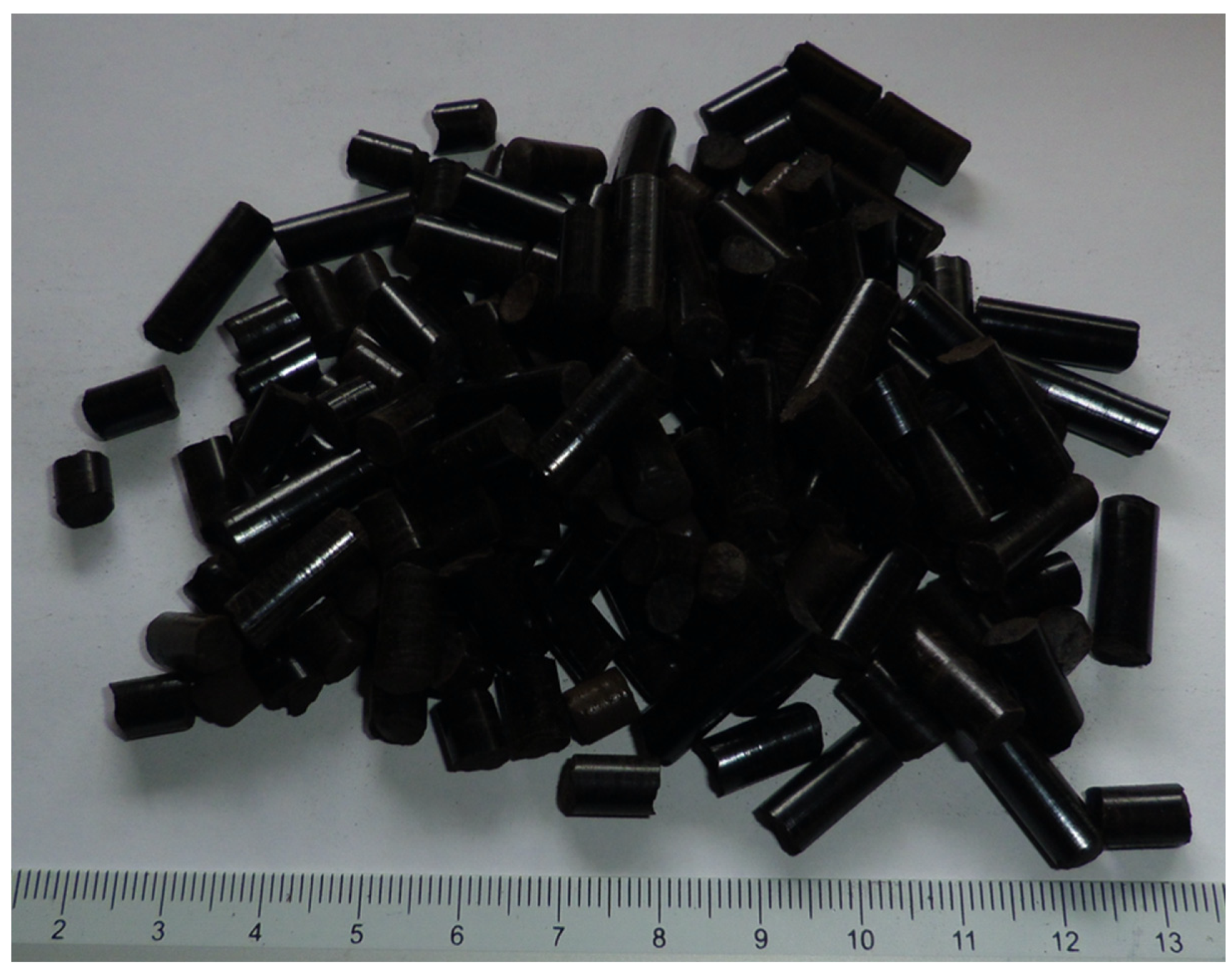
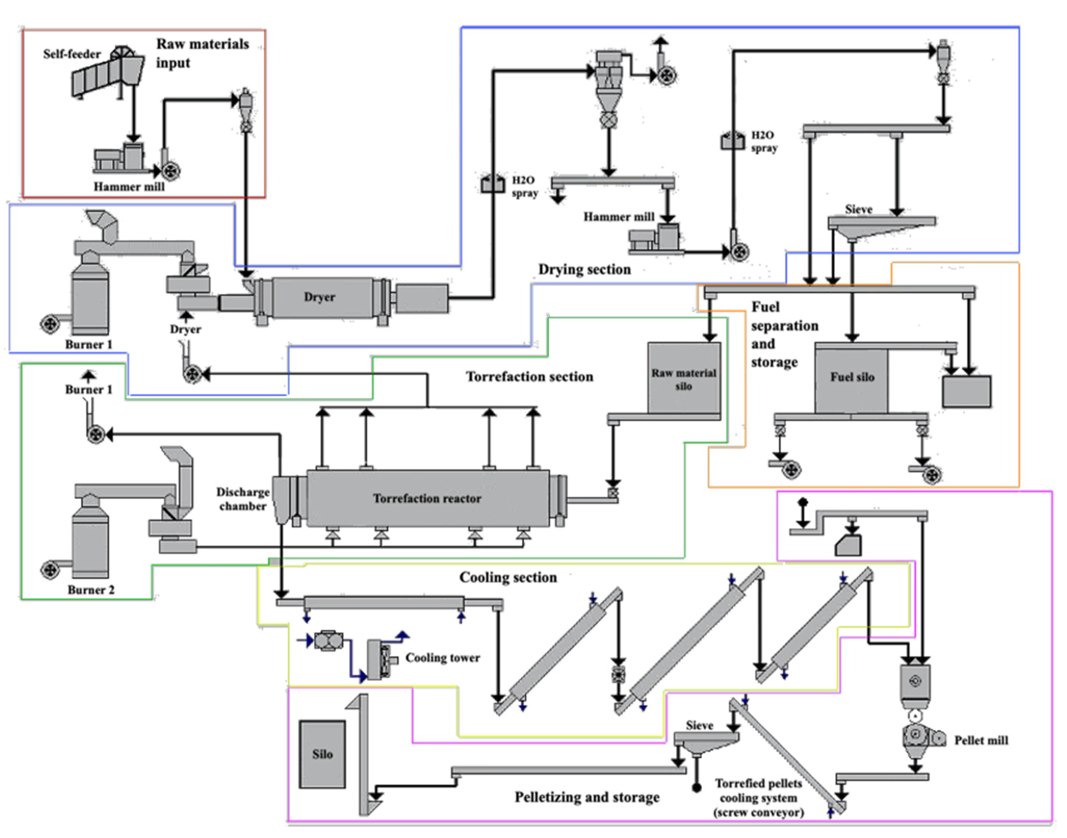
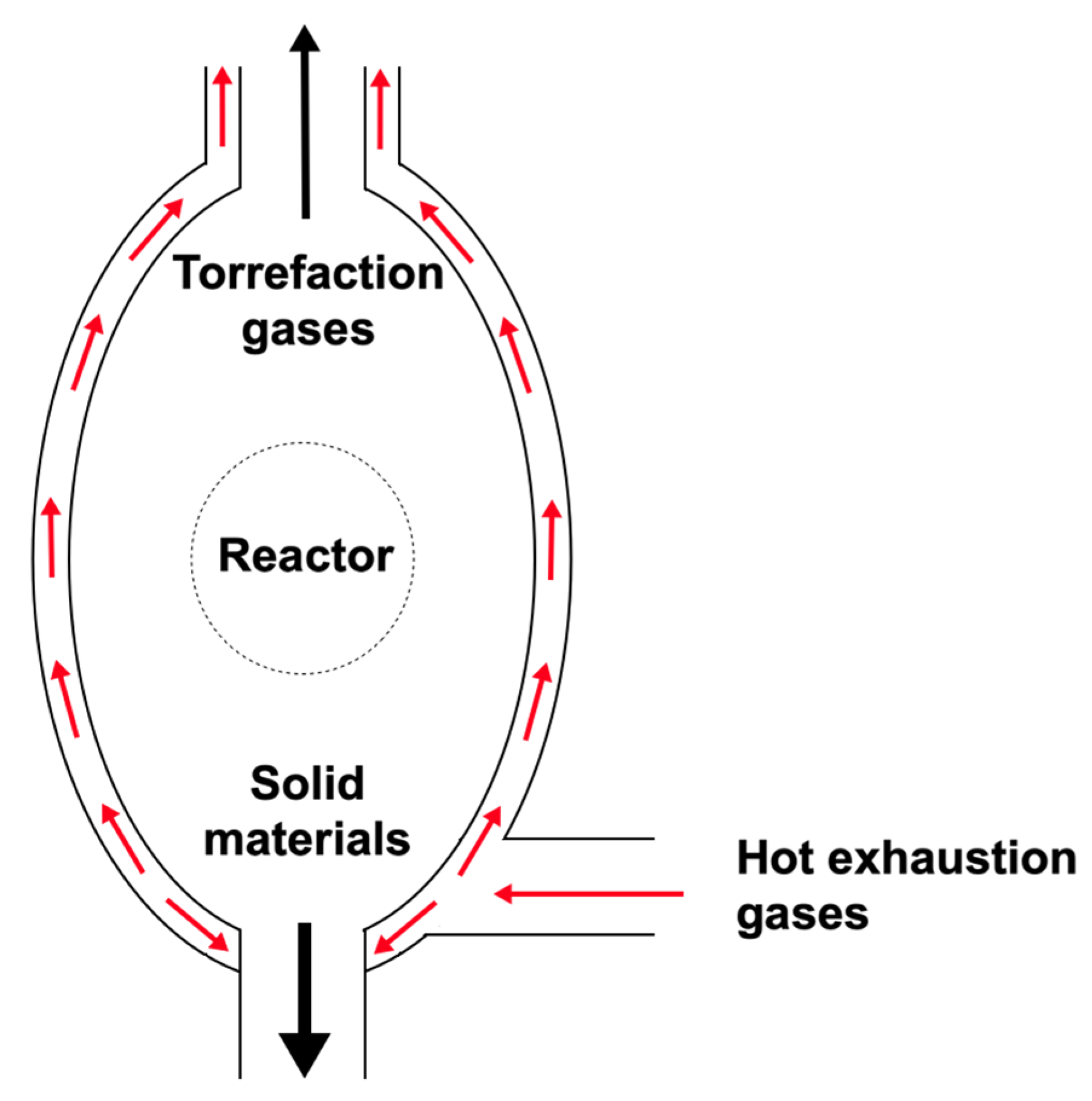
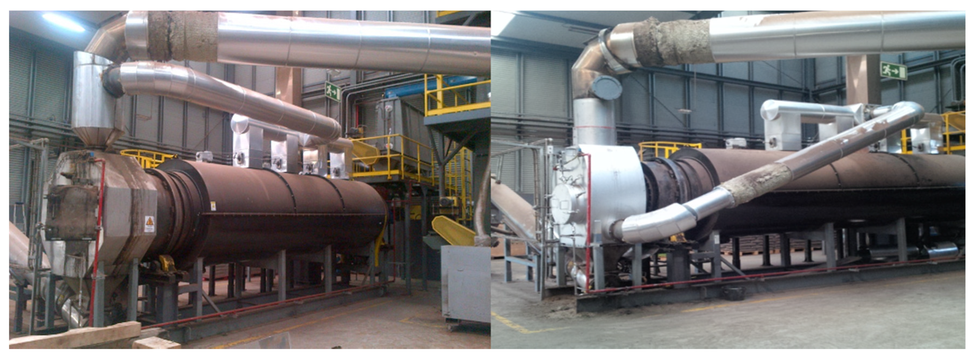
2.2.3. Productive Process

As previously mentioned, this production line, in the final stage of assembly, included pelletizing equipment. The line can be divided into several sections, as shown in Figure 5, which correspond to the different stages of the process.
After the raw material shredding unit, which can be considered a pre-processing step, since it is in this step that the material is received directly from the forest in the form of logs and is transformed into an acceptable format for the production process, the second phase of the process begins. The material, now in the form of chips, is placed in the self-feeder, whose main function is to feed the hammer mill, where chips will undergo a reduction in size of approximately 50% and will be transported to the dryer. The purpose of drying is to reduce the moisture content to levels below 25% and, thus, allow a more efficient torrefaction process.
Then, the material is transported again to another hammer mill, where it undergoes a further reduction in size to obtain a dimension on the largest axis of 6 mm or less. This material is sent to a sieve, where it is separated into two fractions. The fraction between 0 and 2 mm is taken to a silo, where it is stored and later used in biomass furnaces that supply thermal energy to the dryer and to the torrefaction reactor. The fraction between 2 and 6 mm is sent to another silo, from where the torrefaction reactor is fed.
The torrefaction reactor is the central equipment of the entire process. As already mentioned, this is a rotary drum reactor with indirect heating. In other words, the drum where the raw material circulates is heated from the outside, with no direct contact between the hot air stream, resulting from the combustion of biomass, and the raw material. The heat transfer is by means of thermal conduction, while the material circulates inside the central tube, covering the distance between the entry point and the exit point in a determined residence time. This residence time can be reduced by simply increasing the drum’s rotation speed so that the material circulates more quickly.
During the torrefaction process, parts of the constituent material of biomass, namely hemicellulose, are volatilized, which, in fact, defines the process temperature ranges. The volatilized material appears in the form of gases, consisting of two groups. The first is composed by permanent gases, that is, compounds that remain in the gaseous state whatever the pressure and temperature conditions. The second group is composed by condensable gases, which, when there is a change in pressure or temperature conditions, condense and return to the liquid state, which is their natural state of stability, at least within a certain temperature range, and may subsequently exhibit high viscosity, as in the case of tars, or even solidify.
Figure 6 shows schematically the different types of compounds that are formed during the torrefaction process. Contrary to what happens during the pyrolysis process, where the ratio tends to the side of the formation of gaseous and liquid compounds, in torrefaction the ratio tends to the side of the products in the solid state. This solid fraction is formed essentially by the remaining material, from lignin and cellulose, that is not volatilized during the process, since the gas fraction derives mainly from hemicellulose, which is the compound most affected by the increase in temperature. However, in addition to this solid material, there is still a percentage that corresponds to the mineral fraction, namely the ashes. This fraction of ash is directly related to the content of metallic elements present in the biomass used in the torrefaction process, and can vary, even within the same type of biomass, depending on the type of soil or contamination to which it was exposed.
The gas fraction is composed of a diverse number of compounds, the so-called condensable gases, which will convert to the liquid fraction, consisting essentially of water, sugars, acids, alcohols, furans, ketones, terpenes, phenols, waxes and tannins. The permanent gases are made up of hydrogen, carbon monoxide, carbon dioxide, methane, other simple hydrocarbons, toluene and benzene. Other compounds may appear, such as furfural, but the amount is usually less, although its presence is often noted by the sweet aroma that denotes the beginning of its formation.
These gaseous compounds that form during the biomass torrefaction process are commonly referred to as volatile organic compounds (VOCs). However, as can be seen, not all of them correspond to this designation, but are used in industry for practical reasons and for the uniformity of the gases formed. It is also common to all processes with an industrial dimension that these VOCs are valued energetically, so that the process is more energy-efficient, since it is necessary to provide thermal energy for both drying and torrefaction. In reality, the quantities of these gases can reach a level that can cause difficulties in their management, creating flows that are difficult to eliminate. Figure 7 presents an example of these condensed gases, collected in a container placed before these materials are injected for recovery in the furnace of the drying system.
The torrefaction reactor ends in the discharge chamber, which is a section that has two main functions for the process. The first function is the elimination of gases released during the process. This is done by extracting the gases from the upper part of the discharge chamber, and directing them for energy recovery in the drying system furnace. The second function involves the transfer of the solid fraction to the cooling system, composed of a sequence of double-walled augers, where chilled water circulates using a cooling tower placed outside.
The cooling system, composed of the augers, will reduce the temperature from approximately 300 °C to a temperature close to the ambient temperature. This is intended to make the product reach a safe temperature for the following steps, avoiding the ignition of the material when in direct contact with the ambient air. After traveling through the cooling system, the material is poured into a mixing tank, which also functions as intermediate storage, and which controls the admission of material to the conditioning pelletizer auger. It is in the conditioner that the moisture level of the material is corrected, since the moisture content is a determining factor for the pelletization process, working as a lubricant, on the one hand, and in reducing the pellet mill die temperature, on the other.
The pelletizers available on the market, from numerous manufacturers, are divided into two fundamental types: pelletizers with a horizontal axis with a ring die, and pelletizers with a vertical axis with a flat die. The most representative models of the first type are produced by Andritz (Graz, Austria), Salmatec (Gödenstorf, Germany), CPM (Crawfordsville, IN, USA), Bühler (Appenzell, Switzerland) and Prodesa (Zaragoza, Spain), which dominate most of the market, mainly that of the large conventional biomass pellet plants. However, a large number of other manufacturers are disputing the market for small and medium-sized biomass pellet production units. Examples of such companies are La Meccanica (Cittadella, Italy), Muench-Edelstahl (Hilden, Germany) and Mabrik (Barcelona, Spain). The manufacturers identified here, which are all European and North American, are accompanied by a wide range of others, mainly from Asian countries, which are conquering their local markets, mainly due to their lower prices. The flat die pelletizers are represented mainly by the German company Amandus Kahl, but there is also a wide range of other brands, mainly Asian, that use the same system. It should be noted that practically all manufacturers of pelletizers for biomass began with the pelletization of feed for animal consumption, and subsequently moved into biomass, through the structural reinforcement of the equipment to allow them to support greater efforts.
In this YGE production line, La Meccanica equipment was installed, with a production capacity of 1200 kg/h, in other words, a pellet production capacity 40% above the capacity of the torrefaction reactor, which is 720 kg/h. The pellets produced fall directly onto a vibrating channel, which in turn leads them to a conveyor belt and from this to a screen, where dust and non-pelletized materials are separated, to be returned to the mixing tank via a cup conveyor, ensuring recirculation in the process. The sieved material goes to storage in two external silos for later dispatch, as shown in Figure 1.

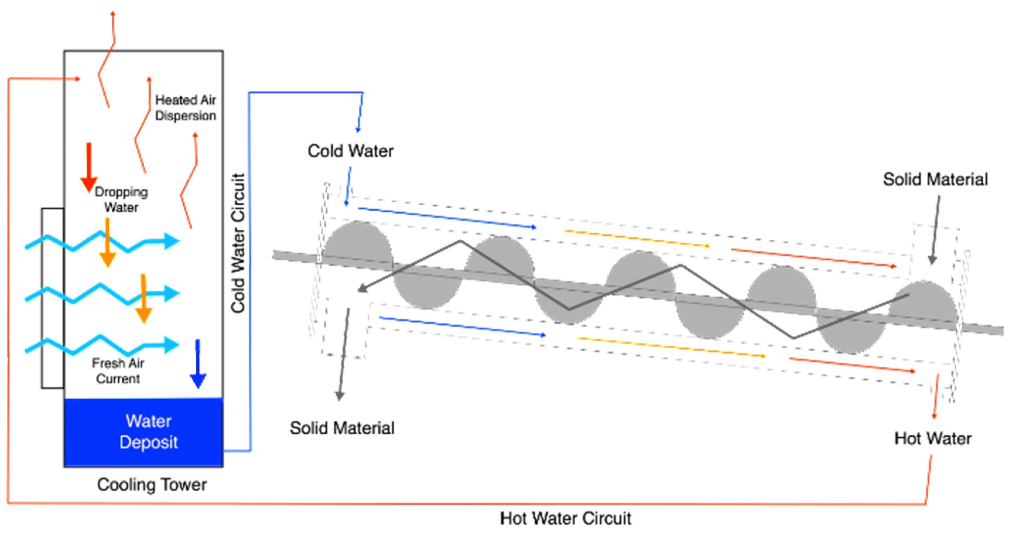
2.2.4. Support Structures

Support structures are those structures essential to the correct operation of the industrial unit, and in this specific case consist of a 630 kVA transformation station, a cooling tower, nitrogen generating equipment (used to make the atmosphere inside the reactor inert in the case of need or risk of ignition), a compressor, and two furnaces, respectively 3 MW and 1.5 MW, for the drying system and the reactor. All gases extracted from the torrefaction process are taken to the 3 MW furnace for energy recovery. The external storage silos are equipped with an automatic unloading system and raised for direct loading of heavy vehicles.

2.3. Identification of Faults, Malfunctions and Process Conditions

2.3.1. Start-Up and First Testing Phase (2013–2014)

After the completion of the construction and equipment assembly work, the unit was started with the first tests and tests to fine-tune the process. However, it quickly became apparent that the unit was not able to operate efficiently in a continuous process, since there was a set of considerations that, despite being apparently minor, in reality threatened to endanger the entire operation. An example of this was the sample collection windows, located in the main transitions between equipment, which caused several ignitions during the operation, because they were not watertight and thus allowed oxygen-rich air to enter the system in areas where the temperature was high.
It was also quickly verified that the cooling system installed was neither sufficient nor efficient to reduce the temperature, since there was ignition of the material, even after the cooling zone, which was initially constituted only by a double-walled auger, where water circulated and was cooled by a radiator with air ventilation, thus demonstrating that the temperature reduction was not sufficient for the amount of mass and heat present in the system.
All these issues indicating that it was not possible to operate the system safely led to the decision to stop the tests and to correct the problems identified. Therefore, changes were made to the cooling system, with three more double-walled augers (Figure 8). The cooling system was also replaced using a radiator with ventilated air, with a cooling tower. Finally, all the non-watertight sampling windows were eliminated, and these were replaced by a watertight sampling system.
Regarding the quality of the final product, at this stage, no results were obtained that would allow the process to be fine-tuned, since the permanent insecurities caused by ignitions made it necessary to interrupt the process many times. Therefore, it was difficult to maintain its stability and thus guarantee the repeatability of the results obtained for the final product. As the temperature considered to be optimal for the process was often exceeded, and the material appeared more carbonized than torrefied, there were frequent problems in pelletizing, causing great wear and tear to the components of the pelletizing equipment. Figure 9 shows examples of this wear caused by the abrasiveness of excessively torrefied material.
This information was extremely important, as it prompted the development of a line of research on the pelletization of the torrefied biomass. At this stage, a lot of data were collected, both on the process itself, namely temperatures and other system variables related to the individual operation of each equipment, and also on the products at different stages of the process. These data were subsequently analyzed and led to the first optimizations of the pelletization process, namely the definition of the type of die to be used for the processing of torrefied biomass.
Initially, the degree of torrefaction was defined only by the temperature of the process, since in this testing phase the residence time and the type of raw material used, which was always Pinus pinaster wood, were kept constant. As all previous experience was based on the production of conventional biomass pellets, the first matrices used in the tests were the same, with high compression rates. After this verification, a relationship was established between the quantitative parameters of the holes in the die and the compression rate as shown in Figure 10.
Thus, the different parameters relate to each other in different ways, allowing a quantification of the compression rate. In this way, with the experience gained, it was possible to empirically define which die is suitable for the torrefied material. At the same time, this enabled the matrices to be replaced by adapting the compression rate, whatever the type, diameter or thickness, since it is sufficient to guarantee the desired value for compression rate, while varying or determining any of the other terms of the equation. Thus, the different lengths of the die hole are related to each other through the equation:
T l = C l + R l
where Tl is total length, Cl is compression length and Rl is relief length. This quantity is expressed in millimeters.
Likewise, the diameter is related to the compression rate through the equation:
C R = C l d
where CR is the compression rate and d is the diameter. This value is dimensionless.
With these relationships, and after defining the ideal compression rate for the different degrees of torrefaction, it became possible to change, for example, the diameter of torrefied biomass pellets to be produced, or to verify whether a die, after rectification, is capable of producing torrefied biomass pellets with the desired quality. However, despite this development that allowed the production of high-quality torrefied biomass pellets, it was not yet possible to stabilize the production process in order to keep the material homogeneous, and there were many fluctuations in quality, mainly with regard to the degree of torrefaction.
This difficulty in maintaining the homogeneity of the production process was essentially due to the fact that biomass is used as a source of thermal energy for the process. Or rather, it was due to the fact that biomass has a high thermal inertia and, therefore, does not allow rapid rises or falls in the temperature of the reactor to stabilize its temperature and, thus, the torrefaction process. This situation, together with the fact that the technology used is a rotary drum reactor with indirect heating, was immediately registered as disadvantageous for the selection of a torrefaction technology for an industrial-scale biomass torrefaction plant, since the greater the quantities of biomass processed, the greater and more difficult to control the problem will be.

2.3.2. Second Testing Phase (2014–2015)

After solving the problems identified during the first testing phase, the second phase started, with the objective of having the unit in operation for the maximum possible continuous time. The intention was to identify other problems that might only occur after some time, and that might somehow condition the operation of the production unit. In this way, the process began, stipulating a temperature considered low, so as to more easily control any sudden temperature rises. Over the following days, with the process stabilized and with the product presenting some interesting characteristics without, however, achieving the desired results as torrefied biomass pellets, it was possible to verify and prove the success of the improvements introduced in the system, since none of the situations described above occurred again during the second testing phase.
Meanwhile, the monitoring of aspects related to the mechanical functioning of the production unit was intensified in order to identify any situation that might be considered critical for normal functioning. It was found that, after about four days of continuous operation, the first auger of the cooling system, which connects the discharge chamber to the second auger, began to show an increase in amperage, indicating an abnormal effort that had not been registered thus far. For this reason, the decision was made to interrupt the test, initiating the stopping procedure and ensuring the safe cooling of the system.
In order to gauge the reason for the large effort, and because it was thought that it could be caused by a warping of the central shaft, it was disassembled, as shown in Figure 11. As is clearly visible in the image, there was a layer of carbonized material mainly in the corresponding section of the shaft that was in contact with the discharge chamber area of the reactor. This situation immediately raised a suspicion regarding the origin of this encrustation of carbonized material located in this area of the auger, mainly because another indication appeared at several points of the production line, associated with the permanent exhaustion of gases in transition zones. This revealed multiple leaks, through which gases escaped, condensing along the surface of the equipment, as can be seen in Figure 12 and Figure 13, where the atmosphere inside the production unit is perfectly visible, completely filled with exhaled gases, as well as runoff along the surfaces of the equipment.
The verification of the two situations, first, the fact that something was agglutinating the solid material, causing it to adhere to the propeller and the central shaft of the first cooling auger and, second, the fact that there were gas leaks along the entire production line, indicated that the volume of gases produced during the torrefaction process was higher than what had initially been admitted. Above all, it was evident that the gas extraction system had been dimensioned in a deficient way and was, therefore, not able to eliminate all the gases produced. This allowed them to follow the solid fraction, since the temperature difference of approximately 80 °C was sufficient to condense some of the gases when they passed from the reactor to the discharge chamber. The liquid formed then dripped on the solid material, creating a paste that, although the temperature being already lower than in the reactor, usually around 300 °C (±10 °C), suffered the effects of a long residence time and was carbonized.
This carbonized material created a thick covering over the shaft and the helix which, in the course of time, became detached, leaving the fragments trapped in the space between the helix and the inner wall of the auger, creating friction and even stopping the movement of the auger, as verified several times when the continuous operation time of 4 to 5 consecutive days was exceeded. This made it necessary to develop a solution to prevent this deposition from happening, because of the more important fact shown in the laboratory that this condensed material impregnated the torrefied biomass pellets, significantly increasing the risk of self-heating and ignition, mainly after the further heating to which the material is then subjected after pelletization, since 94 °C is easily reached when leaving the die.
The tests in the laboratory were carried out in a simple way but were capable of simulating a real situation that could easily happen. That is, the torrefied biomass pellets impregnated by the liquid resulting from the condensation of the torrefaction gases could be subjected to a significant increase in temperature, volatilizing again, and this situation could become dangerous if there was an ignition source nearby, or if the auto-ignition temperature of any of the gases was reached. Figure 14 shows the results of laboratory tests, where a set of pellets of torrefied biomass were deposited on a tray and placed inside a greenhouse previously heated to 95 °C, leaving the door open. The torrefied biomass pellets started igniting immediately, burning without visible flame, demonstrating that the same could easily happen, for example, in material stored in a silo on a summer day.
Another experiment was carried out with a large amount of torrefied biomass pellets, which were collected immediately after leaving the pelletizer. This material was deposited outside, ensuring a safe distance, and was left exposed to the weather. After 4 days, the pile of pellets ignited and had to be extinguished with water. The process was repeated several times, including on several rainy days, when the auto-ignition again occurred and rekindled, even after apparently being extinguished with water. Figure 15 shows one of those moments, with one of the operators of the industrial unit extinguishing another ignition, which occurred on a rainy day.
This situation of self-heating and auto-ignition is associated with the existence of black particles, which, despite being cooled on the outer surface, continue to have a heated core, which slowly transmits the heat stored by thermal conduction to the outside, volatilizing the condensed materials; if there are many black particles, this can cause the materials to auto-ignite. This phenomenon occurs when the particles are not completely cooled. Currently, there is technology available for the detection and control of this type of particle, even in motion, preventing them from accumulating and becoming a problem. However, the best option will always be to cool the particles effectively.
In addition to the danger associated with the self-heating and auto-ignition phenomena, there is also the possibility that the condensed materials will again volatilize and recondense, forming runoff in storage and use areas. Examples of this are shown in Figure 16 and Figure 17, where, respectively, runoff of condensed material from the deposit of a boiler, and runoff on the outer surface of the storage silos of the torrefied biomass pellet production unit itself, can be observed.
After analyzing all the data collected, it was concluded that, despite all the changes made after the first testing phase, it would still be necessary to make some more changes in order to eliminate these problems related to the lack of gas extraction in torrefaction, which were at the origin of the problems of self-heating and auto-ignition, in addition to the problems related to the carbonization of material in the discharge box and in the first cooling auger, as previously described. It was thus decided to conclude this second phase of testing in order to proceed with a new stage of corrections. Of these corrections, two stand out for their importance and dimension.
The first change in the background was to replace the existing discharge chamber with one that is capable of maintaining a high temperature inside, thus preventing gases condensing before they can be sucked up efficiently. This new discharge chamber, with a double wall, allows the circulation of hot air flow from the reactor heating, keeping the temperature high, according to the scheme shown in Figure 18. In Figure 19 the initial and final situation is presented, after installing the new discharge chamber.
The second change involved the cooling of the pelletized material, with the installation of a new cooling auger after the vibrating channel, replacing the conveyor belt, which connected the channel to the fine cleaning screen. Figure 20 shows the operating scheme of the cooling auger.

2.3.3. Third Testing Phase (2015–2016)

After the completion of the alteration work corresponding to the second test phase, a new phase was initiated. The initial objective was the same as in the previous phase, that is, to have the unit in continuous operation for as long as possible, firstly to confirm the efficiency of the changes made, and secondly to check if there would be any more situations that needed intervention.
It was found that the changes were successful and that the unit was able to work continuously for long periods, and it remained at this pace for approximately one and a half years. During this period, data were collected on the functioning and operation of the process, the main objective at this stage being to improve the properties of the final product.

2.3.4. Other Developments (2016–)

After optimizing the process and the product using maritime pine (Pinus pinaster) biomass as raw material, we proceeded to develop a research line on the torrefaction of alternative raw materials, namely exotic forest species that exhibit invasive behavior, such as acacia, but also small and shrubby tree species. Importance was also given to the forms of the residual biomass, namely from the pulp industry and the agro-industrial sector. During this period, the possibility of torrefaction could also be used as a pre-processing technology for other processes, namely other conversion technologies and energy recovery of biomass.

3. Results and Discussion

From the analysis of the cases described in the previous sections, it is possible to understand the main problems associated with increasing the scale of the biomass torrefaction units, namely those associated with the production of torrefied biomass pellets. It was found that the difficulties encountered by many of the industrial projects over the past few years, especially those related to the ability to produce continuously, without forced stops due to contingencies in the process itself, and to the ability to produce pellets of torrefied biomass with good quality, meeting, for example, the requirements presented in ISO/TS 17225-8: 2016 (Solid biofuels—Fuel specifications and classes—Part 8: Graded thermally treated and densified biomass fuels), are fundamentally due to the fact that not all the variables associated with the thermochemical conversion process used, such as biomass torrefaction, were understood and taken into account. Moreover, the intrinsic characteristics of the raw material, namely their chemical and structural composition, and the behavior of each of these compounds during the torrefaction process, were neglected.
If, on the one hand, as seen above, issues related to the elimination of torrefaction gases can interfere with the normal functioning of the industrial process, on the other hand, issues related to the incorrect definition of process parameters directly influence the quality of the final product, being decisive for obtaining good or bad products. In addition to the calorific value, the quality of the final product is also dependent on other factors, such as mechanical durability, bulk density or fines content, all of which are related to operational aspects of the industrial process, but also dependent on the chemical composition of the product’s raw material and, above all, on the correct definition of the operating intervals of the fundamental parameters of the torrefaction process, the temperature and the residence time.
It is the combination of these two factors that will determine the success or failure of the process, so it is essential, before any other corrective measure, to know exactly all the conditions and specificities related to biomass torrefaction, in order to be able to define correctly the torrefaction concept itself. Currently, it is possible to find dozens of definitions available in the most varied types of publication. However, although the vast majority of them are not incorrect, it can be said that they are at least incomplete, focusing only on the issue of temperature and the absence of oxygen, which, as mentioned above, is manifestly insufficient, as this type of definition can be misleading and give the impression that the greater the temperature or residence time the better, as long as the oxygen-poor atmosphere is maintained.
In reality, this may seem true if the objective is only to obtain a product with a high calorific value, but, as already mentioned, this temperature will cause profound changes to the molecular structure of the compounds that make up most of the biomass of vegetable origin. As lignin is a material with an amorphous structure and is the main compound responsible for the agglutination of the particles during the pelletization process, it is important that its structure does not change, because otherwise difficulties will occur during this process. The structural change of lignin from amorphous to crystalline state is widely described in the literature, with temperature and subsequent cooling changing its behavior from ductile to brittle, since the bonds established between the molecules are stronger [41,42,43]. A similar situation occurs with cellulose, which adds to the difficulty of the pelletizing process, making the whole set more friable [44,45,46].
From this perspective, based on the behavior of the main compounds that make up the biomass of vegetable origin as the temperature rises, as shown in Figure 21, the definition of torrefaction should be assumed to be a thermo-chemical conversion technology for biomass, which occurs in a temperature range between 220 and 320 °C, under conditions of atmospheric pressure and in the absence of oxygen, where hemicellulose disintegrates, keeping lignin and cellulose in structural states very close to the original. In other words, with this definition, the torrefaction process takes place within the temperature range where only, or at least mostly, the disintegration of hemicellulose occurs, without affecting, or affecting very little, the other main biomass compounds, lignin and cellulose.
Based on the above and as presented in the previous sections, it can be said that the correct definition of the torrefaction parameters is the main factor that leads to obtaining products with different qualities. An example is given Figure 22, where it is possible to observe on the left side of the figure, pellets produced before the measures related to the extraction of torrefaction gases and post-pelletizing cooling have been corrected, and the temperature and residence time intervals to be used as the basis for the operational procedure defined for the process, and, on the right side of the figure, other pellets produced after implementing these measures during the third testing phase. Obviously, it is still essential to correct any problems related to the operation of the equipment, which are almost always caused by the lack of knowledge and mastery of the torrefaction process, because only after these corrections is it possible to fine-tune the process for a certain type of raw material, with its own specificities and characteristics, referring to the chemical and structural composition of the biomass in question in each case.
Throughout the different phases of testing and fine-tuning the process, data were collected on the product characterization, which are summarized in Table 1. In Table 2 are presented the results obtained from the analysis of the raw materials used to serve as a point of comparison. Another outcome resulting from the performance of these tests was to be able to create an operational procedure that would lead to production in a continuous and repeatable form of pellets of torrefied biomass with good quality, as defined in ISO/TS 17225-8: 2016 (Solid biofuels—Fuel specifications and classes—Part 8: Graded thermally treated and densified biomass fuels). This being the only standard that addresses the technical characteristics of thermally treated biomass for energy applications, it is very important that the material produced meets the parameters established in this regulatory document since, most likely, when the market for torrefied products for energy purposes develops, producers will be asked to prove that they meet these requirements.
There are still few data available on the quality of industrially produced torrefied biomass pellets, as there are still very few successful cases on an industrial scale [29,31,34,47,48]. However, there are already some documented cases of tests carried out involving the substitution of mineral coal in thermoelectric plants with pellets of torrefied biomass [49,50,51,52,53,54]. The data obtained during the testing phases allowed the collection of quantities of data that allowed the delimitation of the intervals within which, with a high degree of certainty, the pellets produced with the selected parameters for the operational procedure will fit. For the remaining values, average values are presented, since these values will depend on the chemical composition, and often even on variations of a local or regional nature.
As can be seen from the values presented, these torrefied biomass pellets are already very close to the values presented by ISO/TS 17225-8: 2016 (Solid biofuels—Fuel specifications and classes—Part 8: Graded thermally treated and densified biomass fuels), lacking only the refinement and improvement of some aspects related to the production process. For example, the debarking of logs before processing will contribute to the reduction of the silica content and, subsequently, to the reduction of the ash content. This is a very important aspect, since the elimination of the bark may also contribute to the reduction of other elements, namely the group of alkali metals, and thus contribute to the increase in the fusibility temperature of the ashes, reducing the problems associated with this situation.

4. Conclusions

Biomass torrefaction is presented as a process capable of improving the properties and combustibility of biomass. However, it is a technology that has not yet been able to prove its concept and definitively prove its potential. The lack of knowledge about the process and the technologies and its operation caused a delay in the implementation of torrefaction as a technology capable of improving the properties of biomass and making it an alternative to fossil fuels, mainly coal.
The realization of studies like the one presented here becomes even more important, because there are no other similar reports which help the industrial sector of torrefied biomass to take the necessary steps for large-scale industrialization through the sharing of experiences and solutions, as this is the only way to create a true market for torrefied biomass.
As regards expanding the size of a torrefaction unit, raising the scale from the laboratory to pilot dimension or from pilot to industrial dimension, further studies are needed, mainly in terms of knowledge of the kinetics of the reactions that occur during the process. This information is essential to help in the design of a larger-scale production unit as it is based on this knowledge of the reaction kinetics that the behavior of certain constituents of biomass can be defined, and based on these, to identify some important parameters, such as the residence time and operating temperature required to obtain a product with specific characteristics.
Although most of the main problems related to the technical operation of a production unit have been largely corrected, there is still a lot of research work on the different forms of biomass and the model of how they react to the torrefaction process. At the same time, it is also necessary to understand how torrefaction can be integrated into other pre-processing and biomass-processing systems, namely gasification.

Author Contributions

Conceptualization, L.J.R.N.; methodology, L.J.R.N.; validation, L.J.R.N.; formal analysis, L.J.R.N.; investigation, L.J.R.N.; resources, L.J.R.N.; data curation, L.J.R.N.; writing—original draft preparation, L.J.R.N.; writing—review and editing, L.J.R.N.; visualization, L.J.R.N.; supervision, L.J.R.N.; project administration, L.J.R.N. The author have read and agreed to the published version of the manuscript.

Funding

This research received no external funding.

Acknowledgments

The author would like to acknowledge the entire Production Department of YGE-Yser Green Energy SA and all the R&D Section of the company as well, for all the efforts and help to achieve the success of the investigation.

Conflicts of Interest

The author declare no conflict of interest.

References

  1. Amasyali, K.; El-Gohary, N.M. A review of data-driven building energy consumption prediction studies. Renew. Sustain. Energy Rev. 2018, 81, 1192–1205. [Google Scholar] [CrossRef]
  2. Holmberg, K.; Erdemir, A. Influence of tribology on global energy consumption, costs and emissions. Friction 2017, 5, 263–284. [Google Scholar] [CrossRef]
  3. Bhattacharya, M.; Paramati, S.R.; Ozturk, I.; Bhattacharya, S. The effect of renewable energy consumption on economic growth: Evidence from top 38 countries. Appl. Energy 2016, 162, 733–741. [Google Scholar] [CrossRef]
  4. Bilgen, S. Structure and environmental impact of global energy consumption. Renew. Sustain. Energy Rev. 2014, 38, 890–902. [Google Scholar] [CrossRef]
  5. Zhou, L.; Li, J.; Li, F.; Meng, Q.; Li, J.; Xu, X. Energy consumption model and energy efficiency of machine tools: A comprehensive literature review. J. Clean. Prod. 2016, 112, 3721–3734. [Google Scholar] [CrossRef]
  6. Zhou, K.; Yang, S. Understanding household energy consumption behavior: The contribution of energy big data analytics. Renew. Sustain. Energy Rev. 2016, 56, 810–819. [Google Scholar] [CrossRef]
  7. Zhang, B.; Wang, B.; Wang, Z. Role of renewable energy and non-renewable energy consumption on EKC: Evidence from Pakistan. J. Clean. Prod. 2017, 156, 855–864. [Google Scholar]
  8. Parikka, M. Global biomass fuel resources. Biomass Bioenergy 2004, 27, 613–620. [Google Scholar] [CrossRef]
  9. Shahbaz, M.; Rasool, G.; Ahmed, K.; Mahalik, M.K. Considering the effect of biomass energy consumption on economic growth: Fresh evidence from BRICS region. Renew. Sustain. Energy Rev. 2016, 60, 1442–1450. [Google Scholar] [CrossRef] [Green Version]
  10. Adewuyi, A.O.; Awodumi, O.B. Biomass energy consumption, economic growth and carbon emissions: Fresh evidence from West Africa using a simultaneous equation model. Energy 2017, 119, 453–471. [Google Scholar] [CrossRef]
  11. Lauri, P.; Havlík, P.; Kindermann, G.; Forsell, N.; Böttcher, H.; Obersteiner, M. Woody biomass energy potential in 2050. Energy Policy 2014, 66, 19–31. [Google Scholar] [CrossRef]
  12. Shahbaz, M.; Balsalobre-Lorente, D.; Sinha, A. Foreign direct Investment–CO2 emissions nexus in Middle East and North African countries: Importance of biomass energy consumption. J. Clean. Prod. 2019, 217, 603–614. [Google Scholar] [CrossRef] [Green Version]
  13. Hall, D.; Rosillo-Calle, F.; Woods, J. Biomass utilization in households & industry: Energy use and development. Chemosphere 1994, 29, 1099–1119. [Google Scholar]
  14. Guo, M.; Song, W.; Buhain, J. Bioenergy and biofuels: History, status, and perspective. Renew. Sustain. Energy Rev. 2015, 42, 712–725. [Google Scholar] [CrossRef]
  15. Weisz, H.; Fischer-Kowalski, M.; Grünbühel, C.M.; Haberl, H.; Krausmann, F.; Winiwarter, V. Global environmental change and historical transitions. Innov. Eur. J. Soc. Sci. Res. 2001, 14, 117–142. [Google Scholar] [CrossRef]
  16. Wang, Z. Does biomass energy consumption help to control environmental pollution? Evidence from BRICS countries. Sci. Total Environ. 2019, 670, 1075–1083. [Google Scholar]
  17. Bennett, K.D.; Simonson, W.D.; Peglar, S.M. Fire and man in post-glacial woodlands of eastern England. J. Archaeol. Sci. 1990, 17, 635–642. [Google Scholar] [CrossRef]
  18. Oakley, K. The earliest fire-makers. Antiquity 1956, 30, 102–107. [Google Scholar] [CrossRef]
  19. Ploetz, R.; Rusdianasari, R.; Eviliana, E. Renewable Energy: Advantages and Disadvantages. In Proceedings of the Forum in Research, Science, and Technology (FIRST); Politeknik Negeri Sriwijaya: Sumatera Selatan, Indonesia, 2016. [Google Scholar]
  20. Yang, Z.; Wu, Y.; Zhang, Z.; Li, H.; Li, X.; Egorov, R.I.; Strizhak, P.A.; Gao, X. Recent advances in co-thermochemical conversions of biomass with fossil fuels focusing on the synergistic effects. Renew. Sustain. Energy Rev. 2019, 103, 384–398. [Google Scholar] [CrossRef]
  21. Moharamian, A.; Soltani, S.; Rosen, M.A.; Mahmoudi, S.; Morosuk, T. Exergoeconomic analysis of natural gas fired and biomass post-fired combined cycle with hydrogen injection into the combustion chamber. J. Clean. Prod. 2018, 180, 450–465. [Google Scholar] [CrossRef]
  22. Liu, Z. China’s strategy for the development of renewable energies. Energy Sources Part B Econ. Plan. Policy 2017, 12, 971–975. [Google Scholar] [CrossRef] [Green Version]
  23. Vassilev, S.V.; Vassileva, C.G.; Vassilev, V.S. Advantages and disadvantages of composition and properties of biomass in comparison with coal: An overview. Fuel 2015, 158, 330–350. [Google Scholar] [CrossRef]
  24. Suzuki, K.; Tsuji, N.; Shirai, Y.; Hassan, M.A.; Osaki, M. Evaluation of biomass energy potential towards achieving sustainability in biomass energy utilization in Sabah, Malaysia. Biomass Bioenergy 2017, 97, 149–154. [Google Scholar] [CrossRef]
  25. Gustavsson, L. Energy efficiency and competitiveness of biomass-based energy systems. Energy 1997, 22, 959–967. [Google Scholar] [CrossRef]
  26. Stupak, I.; Asikainen, A.; Jonsell, M.; Karltun, E.; Lunnan, A.; Mizaraitė, D.; Pasanen, K.; Pärn, H.; Raulund-Rasmussen, K.; Röser, D. Sustainable utilisation of forest biomass for energy—Possibilities and problems: Policy, legislation, certification, and recommendations and guidelines in the Nordic, Baltic, and other European countries. Biomass Bioenergy 2007, 31, 666–684. [Google Scholar] [CrossRef]
  27. Heyat, M.B.B.; Akhtar, F.; Shaguftah, N.A. An Overview of Renewable Energy. Int. J. Tech. Res. Sci. 2016, 1, 119–121. [Google Scholar]
  28. Ribeiro, J.M.C.; Godina, R.; Matias, J.C.d.O.; Nunes, L.J.R. Future perspectives of biomass torrefaction: Review of the current state-of-the-art and research development. Sustainability 2018, 10, 2323. [Google Scholar] [CrossRef] [Green Version]
  29. Proskurina, S.; Heinimö, J.; Schipfer, F.; Vakkilainen, E. Biomass for industrial applications: The role of torrefaction. Renew. Energy 2017, 111, 265–274. [Google Scholar] [CrossRef]
  30. Doassans-Carrère, N.; Muller, S.; Mitzkat, M. REVE—A new industrial technology for biomass torrefaction: Pilot studies. Fuel Process. Technol. 2014, 126, 155–162. [Google Scholar] [CrossRef]
  31. Shankar Tumuluru, J.; Sokhansanj, S.; Hess, J.R.; Wright, C.T.; Boardman, R.D. A review on biomass torrefaction process and product properties for energy applications. Ind. Biotechnol. 2011, 7, 384–401. [Google Scholar] [CrossRef] [Green Version]
  32. Herbert, G.J.; Krishnan, A.U. Quantifying environmental performance of biomass energy. Renew. Sustain. Energy Rev. 2016, 59, 292–308. [Google Scholar] [CrossRef]
  33. Da Silva, C.M.S.; Carneiro, A.d.C.O.; Vital, B.R.; Figueiró, C.G.; De Freitas Fialho, L.; De Magalhães, M.A.; Carvalho, A.G.; Cândido, W.L. Biomass torrefaction for energy purposes–Definitions and an overview of challenges and opportunities in Brazil. Renew. Sustain. Energy Rev. 2018, 82, 2426–2432. [Google Scholar] [CrossRef]
  34. Chen, W.-H.; Peng, J.; Bi, X.T. A state-of-the-art review of biomass torrefaction, densification and applications. Renew. Sustain. Energy Rev. 2015, 44, 847–866. [Google Scholar] [CrossRef]
  35. Thrän, D.; Witt, J.; Schaubach, K.; Kiel, J.; Carbo, M.; Maier, J.; Ndibe, C.; Koppejan, J.; Alakangas, E.; Majer, S. Moving torrefaction towards market introduction–Technical improvements and economic-environmental assessment along the overall torrefaction supply chain through the SECTOR project. Biomass Bioenergy 2016, 89, 184–200. [Google Scholar] [CrossRef] [Green Version]
  36. Batidzirai, B.; Mignot, A.; Schakel, W.; Junginger, H.; Faaij, A. Biomass torrefaction technology: Techno-economic status and future prospects. Energy 2013, 62, 196–214. [Google Scholar] [CrossRef]
  37. Acharya, B.; Dutta, A.; Minaret, J. Review on comparative study of dry and wet torrefaction. Sustain. Energy Technol. Assess. 2015, 12, 26–37. [Google Scholar] [CrossRef]
  38. Uchezuba, D.I.; Mbai, S.; Zimmermann, I.; Bruwer, J. Investigating wood pellet torrefaction investment and its economic feasibility in the Krumhuk, Khomas region of Namibia. SN Appl. Sci. 2019, 1, 402. [Google Scholar] [CrossRef] [Green Version]
  39. Kuzmina, J.; Sytchev, G.; Zaychenko, V. Torrefaction. prospects and application. Chem. Eng. Trans. 2016, 50, 265–270. [Google Scholar]
  40. Thompson, N.A.; Herrmann, A.M.; Hekkert, M.P. How sustainable entrepreneurs engage in institutional change: Insights from biomass torrefaction in the Netherlands. J. Clean. Prod. 2015, 106, 608–618. [Google Scholar] [CrossRef]
  41. Chen, W.-H.; Kuo, P.-C. Torrefaction and co-torrefaction characterization of hemicellulose, cellulose and lignin as well as torrefaction of some basic constituents in biomass. Energy 2011, 36, 803–811. [Google Scholar] [CrossRef]
  42. Pelaez-Samaniego, M.R.; Yadama, V.; Garcia-Perez, M.; Lowell, E.; McDonald, A.G. Effect of temperature during wood torrefaction on the formation of lignin liquid intermediates. J. Anal. Appl. Pyrolysis 2014, 109, 222–233. [Google Scholar] [CrossRef]
  43. Chen, W.-H.; Kuo, P.-C. Isothermal torrefaction kinetics of hemicellulose, cellulose, lignin and xylan using thermogravimetric analysis. Energy 2011, 36, 6451–6460. [Google Scholar] [CrossRef]
  44. Hilbers, T.J.; Wang, Z.; Pecha, B.; Westerhof, R.J.; Kersten, S.R.; Pelaez-Samaniego, M.R.; Garcia-Perez, M. Cellulose-Lignin interactions during slow and fast pyrolysis. J. Anal. Appl. Pyrolysis 2015, 114, 197–207. [Google Scholar] [CrossRef] [Green Version]
  45. Mazeau, K.; Heux, L. Molecular dynamics simulations of bulk native crystalline and amorphous structures of cellulose. J. Phys. Chem. B 2003, 107, 2394–2403. [Google Scholar] [CrossRef]
  46. Dutta, S.; Wu, K.C.-W.; Saha, B. Emerging strategies for breaking the 3D amorphous network of lignin. Catal. Sci. Technol. 2014, 4, 3785–3799. [Google Scholar] [CrossRef]
  47. Rudolfsson, M.; Borén, E.; Pommer, L.; Nordin, A.; Lestander, T.A. Combined effects of torrefaction and pelletization parameters on the quality of pellets produced from torrefied biomass. Appl. Energy 2017, 191, 414–424. [Google Scholar] [CrossRef]
  48. Ghiasi, B.; Kumar, L.; Furubayashi, T.; Lim, C.J.; Bi, X.; Kim, C.S.; Sokhansanj, S. Densified biocoal from woodchips: Is it better to do torrefaction before or after densification? Appl. Energy 2014, 134, 133–142. [Google Scholar] [CrossRef]
  49. Nunes, L.; Matias, J.; Catalão, J. A review on torrefied biomass pellets as a sustainable alternative to coal in power generation. Renew. Sustain. Energy Rev. 2014, 40, 153–160. [Google Scholar] [CrossRef]
  50. Ndibe, C.; Maier, J.; Scheffknecht, G. Combustion, cofiring and emissions characteristics of torrefied biomass in a drop tube reactor. Biomass Bioenergy 2015, 79, 105–115. [Google Scholar] [CrossRef]
  51. Agar, D.; Wihersaari, M. Bio-coal, torrefied lignocellulosic resources–Key properties for its use in co-firing with fossil coal–Their status. Biomass Bioenergy 2012, 44, 107–111. [Google Scholar] [CrossRef]
  52. Bergman, P.C.; Boersma, A.; Zwart, R.; Kiel, J. Torrefaction for Biomass Co-Firing in Existing Coal-Fired Power Stations; ECN-C-05-013; Energy Research Centre of the Netherlands: Petten, The Netherlands, 2005. [Google Scholar]
  53. Mun, T.-Y.; Tumsa, T.Z.; Lee, U.; Yang, W. Performance evaluation of co-firing various kinds of biomass with low rank coals in a 500 MWe coal-fired power plant. Energy 2016, 115, 954–962. [Google Scholar] [CrossRef]
  54. Kabir, M.R.; Kumar, A. Comparison of the energy and environmental performances of nine biomass/coal co-firing pathways. Bioresour. Technol. 2012, 124, 394–405. [Google Scholar] [CrossRef] [PubMed]
Figure 1. Exterior of the YGE—Yser Green Energy SA torrefied biomass production unit in full operation, in the locality of Oliveira de Azeméis, in the district of Aveiro (North of Portugal).
Applsci 10 02546 g001
Figure 2. Left: the suction unit and the feed to the hammer mill. The material after grinding is sent to the intermediate storage silo to supply the pelletizer. Right: suction of the torrefied material into the grinding system.
Applsci 10 02546 g002
Figure 3. Sequence of events during the pelletization tests. Left: the pile already mixed and homogenized. Center: a view of the pelletizer used in the tests. Right: the product at the exit.
Applsci 10 02546 g003
Figure 4. Appearance of the final product. Despite the excellent appearance, this material is not feasible with the equipment currently available on the market.
Applsci 10 02546 g004
Figure 5. Different sections that form the production line of YGE—Yser Green Energy SA.
Applsci 10 02546 g005
Figure 6. Main constituent compounds of each of the fractions formed during the torrefaction process.
Applsci 10 02546 g006
Figure 7. Liquid fraction made up mostly of water. Despite being a product with low calorific value, its valorization allows the reduction of the energy costs of the process, at the same time that it allows the elimination of products that cannot be simply emitted into the atmosphere or dumped in the public domain.
Applsci 10 02546 g007
Figure 8. Cut of one of the double-walled augers of the cooling system, in which the chamber where the cooling water circulates is visible. The heat is dissipated by conduction through the cooled walls of the auger in contact with the material that circulates inside.
Applsci 10 02546 g008
Figure 9. Left: the appearance of a new layer of a pelletizer roll. Center: the wear caused on the cover of a pelletizer roll after 200 h in the production of conventional biomass pellets. Right: the wear caused on the cover of a pelletizer roller after 50 h of processing torrefied biomass.
Applsci 10 02546 g009
Figure 10. Scheme of the relationship between the constituent parameters between the holes in a pellet mill die, where Cl is the compression length, Rl is the relief length, Tl is the total length and d is the diameter.
Applsci 10 02546 g010
Figure 11. Propeller of the first auger in the cooling system. Both the shaft and the propeller are covered in a black material, similar to coal, indicating that the material may have been exposed to high temperatures, or an excessive residence time.
Applsci 10 02546 g011
Figure 12. View of the atmosphere inside the production unit, with the gases occupying the space completely and exiting through several holes along the production line.
Applsci 10 02546 g012
Figure 13. Condensation of gases forming runoff along the surface of the equipment. Left: runoffs from the manhole door of the reactor discharge chamber. Right: runoffs on the door of the pelletizer itself, that is, in the final section of the production line.
Applsci 10 02546 g013
Figure 14. Torrefied biomass pellets submitted to a temperature of approximately 95 °C.
Applsci 10 02546 g014
Figure 15. Production plant operator extinguishing an auto-ignition in a pile of torrefied biomass pellets.
Applsci 10 02546 g015
Figure 16. Condensate runoff in a boiler where the torrefied biomass pellets were being tested.
Applsci 10 02546 g016
Figure 17. Condensate runoff in the silos of the torrefied biomass pellet production unit.
Applsci 10 02546 g017
Figure 18. Layout of the double-walled discharge chamber to ensure heating and prevent condensation of the torrefaction gases.
Applsci 10 02546 g018
Figure 19. Left: the original unloading chamber, with a simple wall. As shown, the reactor heating gases were already conducted to guarantee the heating of the torrefaction gases. Right: in the new discharge chamber, gases started to be conducted from the bottom of the chamber, ensuring that the high temperature was maintained.
Applsci 10 02546 g019
Figure 20. Scheme of operation of the cooling auger for the torrefied biomass pellets.
Applsci 10 02546 g020
Figure 21. Exemplary model of the behavior of the main components of biomass of vegetal origin with the increase of the temperature. Blue square figure represents the temperature range where torrefaction occurs, when considered the definition of torrefaction as being a thermochemical conversion process occurring in a temperature range between 220 and 320 °C, under atmospheric pressure conditions and in the absence of oxygen, where the molecular disintegration of the hemicellulose occurs, maintaining lignin and cellulose in its original state and structures. This definition was developed during the development to refine the torrefaction process in the pilot unit under analysis.
Applsci 10 02546 g021
Figure 22. Left: pellets produced with torrefied biomass before the problems caused by poor extraction of the torrefaction gases have been solved. Visual analysis shows that they have a poorly consolidated appearance, despite the low degree of torrefaction indicated by the brownish color. Right: pellets of torrefied biomass produced after the implementation of the aforementioned corrective measures.
Applsci 10 02546 g022
Table 1. Summary of the results obtained during the different phases of tests carried out between 2013 and 2016.
PropertiesUnitsValuesTest Reference
DimensionsDiametermm6–10EN16127
Lenghtmm3.15–35EN16127
Thermogravimetric Analysis (db)Moisture%3–8EN14774-2
Volatiles%60–68EN15148
Fixed Carbon%25–30 ------
Ashes%<3EN14775
Elemental Analysis (db)C%52–58EN15104
H%4–6EN15104
O%37–39EN15104
N%<0.500EN15104
S%<0.03EN15289
Cl%<0.02EN15289
Heating ValueHHV (ar) MJ/kg22–23EN14918
LHV (ar) MJ/kg19.5–22EN14918
Bulk Densitykg/m3650–750EN15103
Mechanical DurabilityDurability%97.5–99EN15210-1
Fines%<3EN15210-1
Minor Elements Analysis—ICP (db)Almg/kg3500EN15290/EN15297
Asmg/kg<1EN15290/EN15297
Cdmg/kg<0.5EN15290/EN15297
Camg/kg1500EN15290/EN15297
Crmg/kg<10EN15290/EN15297
Cumg/kg<10EN15290/EN15297
Femg/kg2800EN15290/EN15297
Pbmg/kg<10EN15290/EN15297
Mgmg/kg2000EN15290/EN15297
Pmg/kg200EN15290/EN15297
Kmg/kg2000EN15290/EN15297
Namg/kg200EN15290/EN15297
Simg/kg13,000EN15290/EN15297
Timg/kg250EN15290/EN15297
Mnmg/kg180EN15290/EN15297
Hgmg/kg<0,1EN15290/EN15297
Nimg/kg<10EN15290/EN15297
Znmg/kg<100EN15290/EN15297
Ashes Fusibility—Oxidizing AtmosphereShrinking T.°C1100CEN/TS15370-1
Softening T.°C1250CEN/TS15370-1
Hemispherical T.°C1250CEN/TS15370-1
Fluid T.°C1250CEN/TS15370-1
Ashes Fusibility—Reducing AtmosphereShrinking T.°C800CEN/TS15370-1
Softening T.°C1250CEN/TS15370-1
Hemispherical T.°C1250CEN/TS15370-1
Fluid T.°C1250CEN/TS15370-1
Notes: HHV—High Heating Value; LHV—Low Heating Value; ar—as received; db—dry basis.
Table 2. Summary of the results obtained for raw materials used during the different phases of tests carried out between 2013 and 2016. Raw material was exclusively maritime pine woodchips.
PropertiesUnitsValuesTest Reference
Thermogravimetric Analysis (db)Moisture%10–25EN14774-2
Volatiles%60–70EN15148
Fixed Carbon%16–20------
Ashes%<2EN14775
Elemental Analysis (db)C%50–56EN15104
H%4–6EN15104
O%36–38EN15104
N%<0.500EN15104
S%<0.03EN15289
Cl%<0.02EN15289
Heating ValueHHV (ar) MJ/kg18–19EN14918
LHV (ar) MJ/kg16–17EN14918
Bulk Densitykg/m3250–350EN15103
Asmg/kg<1EN15297
Cdmg/kg<0.5EN15297
Cumg/kg<10EN15297
Pbmg/kg<10EN15297
Mgmg/kg2000EN15297
Nimg/kg<10EN15297
Znmg/kg<100EN15297
Ashes Fusibility—Oxidizing AtmosphereShrinking T.°C1100CEN/TS15370-1
Softening T.°C1200CEN/TS15370-1
Hemispherical T.°C1200CEN/TS15370-1
Fluid T.°C1200CEN/TS15370-1
Ashes Fusibility—Reducing AtmosphereShrinking T.°C800CEN/TS15370-1
Softening T.°C1200CEN/TS15370-1
Hemispherical T.°C1200CEN/TS15370-1
Fluid T.°C1200CEN/TS15370-1

