A Displacement Measuring Interferometer Based on a Frequency-Locked Laser Diode with High Modulation Frequency


1
School of Mechanical Engineering, Hanoi University of Science and Technology, Hanoi 100000, Vietnam
2
College of Systems Engineering and Science, Shibaura Institute of Technology, Tokyo 135-8548, Japan
*
Author to whom correspondence should be addressed.
Appl. Sci. 2020, 10(8), 2693; https://0-doi-org.brum.beds.ac.uk/10.3390/app10082693
Submission received: 9 March 2020
/
Revised: 30 March 2020
/
Accepted: 9 April 2020
/
Published: 13 April 2020
(This article belongs to the Collection Optical Design and Engineering)
Abstract
:Laser interferometers can achieve a nanometer-order uncertainty of measurements when their frequencies are locked to the reference frequencies of the atom or molecule transitions. There are three types of displacement-measuring interferometers: homodyne, heterodyne, and frequency modulation (FM) interferometers. Among these types of interferometer, the FM interferometer has many advantageous features. The interference signal is a series of time-dependent harmonics of modulation frequency, so the phase shift can be detected accurately using the synchronous detection method. Moreover, the FM interferometer is the most suitable for combination with a frequency-locked laser because both require frequency modulation. In previous research, low modulation frequencies at some tens of kHz have been used to lock the frequency of laser diodes (LDs). The low modulation frequency for the laser source means that the maximum measurement speed of the FM interferometers is limited. This paper proposes a novel contribution regarding the application of a high-frequency modulation for an LD to improve both the frequency stability of the laser source and the measurement speed of the FM interferometer. The frequency of the LD was locked to an I2 hyperfine component at 1 MHz modulation frequency. A high bandwidth lock-in amplifier was utilized to detect the saturated absorption signals of the I2 hyperfine structure and induce the signal to lock the frequency of the LD. The locked LD was then used for an FM displacement measuring interferometer. Moreover, a suitable modulation amplitude that affected the signal-to-noise ratio of both the I2 absorption signal and the harmonic intensity of the interference signal was determined. In order to verify the measurement resolution of the proposed interferometer, the displacement induced by a piezo electric actuator was concurrently measured by the interferometer and a capacitive sensor. The difference of the displacement results was less than 20 nm. To evaluate the measurement speed, the interferometer was used to measure the axial error of a high-speed spindle at 500 rpm. The main conclusion of this study is that a stable displacement interferometer with high accuracy and a high measurement speed can be achieved using an LD frequency locked to an I2 hyperfine transition at a high modulation frequency.
1. Introduction
Laser interferometers now play a significant role in high-precision displacement measurements. However, the intensity and frequency instability of the light source dominates the measurement uncertainty of displacement-measuring interferometers. Normally, thermally-stabilized He–Ne lasers, of single or dual frequency, are used [1,2,3,4]. However, a frequency stability in the order of 10−6–10−8 and an intensity stability of 0.1% are insufficient for measurements at a nanometer order of accuracy. Moreover, He–Ne laser sources are voluminous and have a short lifetime, low output power, and high operating voltage. Compared with He–Ne lasers, laser diodes (LDs) have some advantageous features, such as compactness, a long operating time, a high output power, and a wide range of wavelengths. However, the frequency of LDs changes rapidly due to temperature fluctuations or impure injection currents. Current efforts aim to stabilize the frequency of LDs by locking to the reference frequency of atoms or molecules [5,6,7].
In high-precision displacement measurements, some well-known types of interferometer have been developed: homodyne, heterodyne, and frequency modulation (FM) interferometers. The homodyne interferometer can achieve a measurement resolution at a picometer level in some special conditions [8,9]. Unfortunately, the measurement uncertainty of homodyne interferometers is dominated by both the frequency and intensity instability of the light source, environmental disturbances, and the misalignment of optics. Moreover, the short measurement range and ambiguity of direction also limit the application of homodyne interferometers in industry. A heterodyne interferometer is less sensitive to environmental changes, but the maximum measurable speed of a heterodyne interferometer is limited by the heterodyne frequency [10,11,12]. The high cost and complicated system are other disadvantages of heterodyne interferometers. Among these interferometers, the FM interferometer offers some advantages. The time-dependent interference signal of an FM interferometer is a series of harmonics of the modulation frequency. Two consecutive harmonics in the interference signal can be detected synchronously by lock-in amplifiers (LIAs) to determine the phase shift and then to calculate the displacement. The LIA detects the specific harmonic in which the frequency synchronizes with the reference signal and removes anything unsynchronized with the reference signal. Therefore, the LIA can detect a weak signal buried in a strong noise, and hence, the effect of the imperfect inference signal caused by environmental disturbance or light source instability can be reduced. However, the measurement speed of LIAs is limited by the cutoff frequencies of the lowpass filters, and the cutoff frequencies must be less than the modulation frequency. This means that a higher modulation frequency for LDs can achieve a higher measurement speed of the FM interferometer. Another drawback of the FM is that the harmonic intensities depend on the modulation index of the LD via the presence of the Bessel functions. The modulation index is a function of the modulation excursion [13,14].
In previous works, the high-frequency stability of LD sources by locking them to I2 hyperfine transitions was proposed [15,16,17,18,19]. To lock the frequency of LDs, their frequencies must be modulated and turned around the frequency transition of I2. LDs offer direct frequency modulation by modulating the injection current and turn over long ranges without mode-hopping. Therefore, electro-optic modulators (EOMs) and frequency shifters are unnecessary. The systems are stable and compact and do not suffer from the residual amplitude modulation effect of EOMs [20,21,22,23]. The relative frequency stability of locked LDs can reach 10−9 or 10−11, and they can improve the measurement accuracy of laser interferometers. A limitation in previous works has been that the modulation frequency was very low, sometimes at the kHz level. For an FM interferometer, the low modulation frequency means a low measurement speed.
In this paper, a high modulation frequency of 1 MHz is applied to the LD, and its frequency is tuned around the transition 6–3, P(33) of 127I2. The hyperfine structure of the transition is detected using a high bandwidth lock-in amplifier (LIA), up to 50 MHz. The frequency of the LD is locked to the b21 hyperfine component and then employed for the FM displacement-measuring interferometer. Moreover, a suitable modulation excursion is determined to obtain a high signal-to-noise ratio of both the I2 absorption and the harmonic intensities. The intensity fluctuation of the LD source is removed using the ratio of two consecutive harmonics, and the direction of movement is tracked in real-time. To verify the measurement error, the displacement-measuring result of the proposed interferometer is compared with that of a capacitive sensor. In order to prove the improvement of the new system, a comparison between the new results and our previous result is shown in detail. Additionally, the performance of the FM interferometer in the presence of vibration and environmental disturbance is examined. The interferometer is used to measure the axial error of a high-speed spindle at a speed of 500 rpm. The capability of the interferometer for high-speed measurement is confirmed as well.
In summary, the main contributions of this paper are listed as follows: (1) the use of a high modulation frequency of 1 MHz to improve both the frequency stability for the LD and the measurement speed of the FM interferometer; (2) the determination of modulation excursion to enhance the signal-to-noise ratio of the I2 absorption signal and the strength of the harmonic signal; (3) the verification of the measurement resolution of the stabilized LD-based FM interferometer at a high modulation frequency; and (4) the measurement of the axial error of a high-speed spindle at 500 rpm using the proposed interferometer. This study shows that a high measurement speed and a nanometer resolution of the displacement measurement can be achieved using a frequency-stabilized LD-based interferometer. This is very significant because LD sources are commonly used in industrial applications. The proposed interferometer can be used for many fields of technology such as nanotechnology, semiconductor technology, and precision manufacturing technology.
2. Methodology
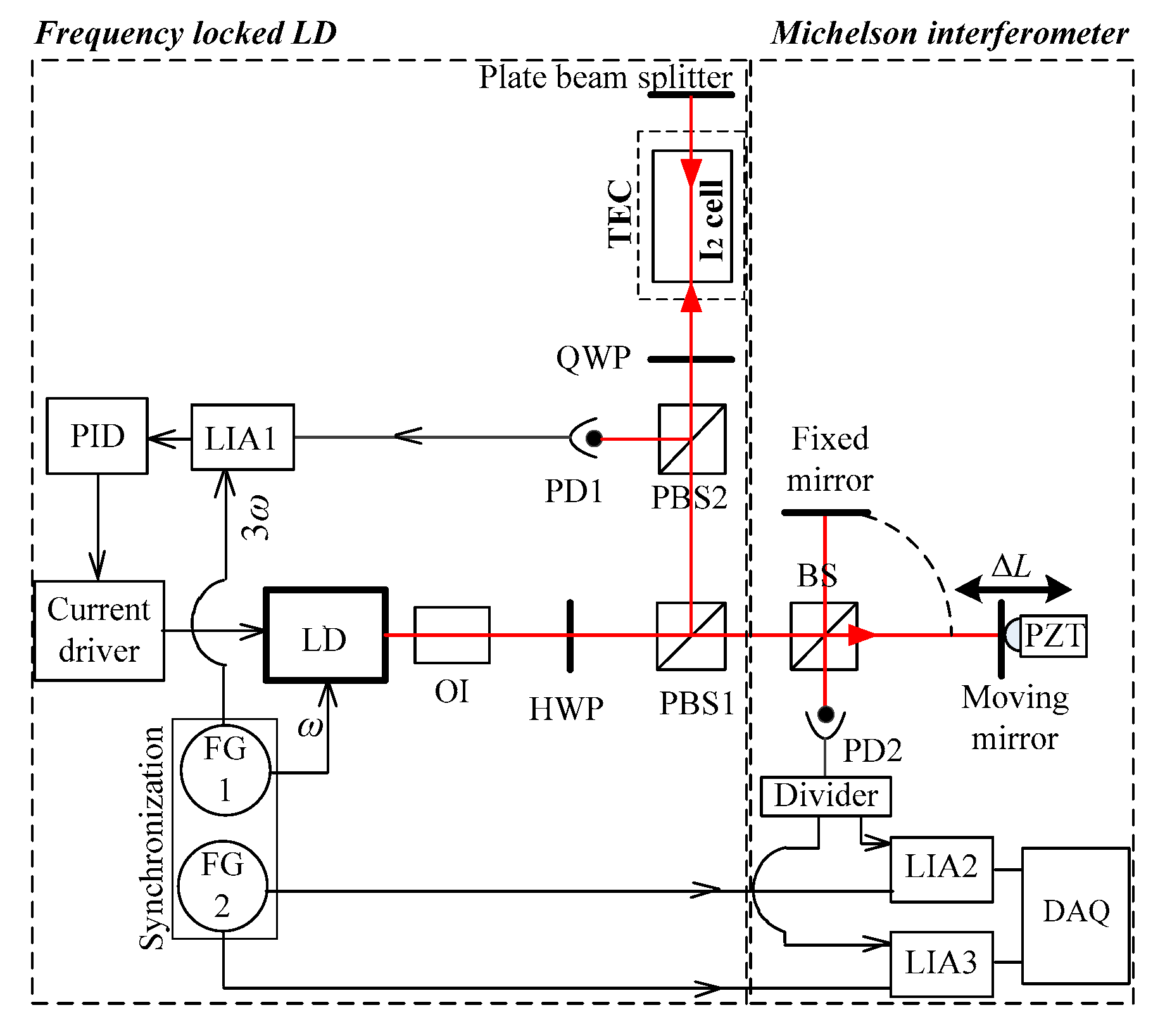
The proposed displacement-measuring interferometer was constructed of two parts: a frequency-locked LD source and a Michelson interferometer; see Figure 1. The I2 hyperfine structure that spreads from 500 to 905 nm provided a large number of stable references to lock the LD frequency. The hyperfine structurer was detected using a saturated absorption configuration. The frequency of the LD was modulated by modulating the injection current. An isolator was employed to prevent laser feedback to the source that could cause frequency instability. A half-wave plate (HWP) and a polarization beam splitter (PBS1) were used to control the intensity of the reflected and transmitted beams. The reflected beam with high intensity went to the I2 cell, and the transmitted beam travelled toward the Michelson interferometer. The reflected beam, i.e., a pump beam, passed through the I2 medium and then bounded to a plate beam splitter. A small part of the pump beam reflected on the plate beam splitter and returned to the I2 cell on the same path, i.e., a probe beam. A quarter-wave plate (QWP) and PBS2 directed the probe beam to Photo Detector 1 (PD1). The signal from PD1 was demodulated using the lock-in amplifier 1 (LIA1). The demodulated signal was the third harmonic of the absorption signal of the I2 hyperfine structure. The demodulated signal induced by LIA1 with the zero-crossing was used as the error signal to feed into a proportional–integral–derivative (PID) controller. The PID controller generated a feedback signal and sent it to the laser controller to lock the frequency of the LD to the I2 hyperfine component.
The frequency-locked LD was installed in the Michelson interferometer. On a beam splitter (BS), the beam was divided into two paths: one went to the measurement mirror, which was attached to a piezoelectric transducer (PZT) or a spindle under test; the other beam travelled to the fixed mirror and was reflected to the BS. The two beams recombined and interfered on the BS. The interference signal was detected using PD2. Typically, the measurement accuracy of displacement-measuring interferometers strongly depends on the quality of the interference signals. However, the proposed interferometer used LIAs to detect harmonics from the interference signal and then to calculate the displacement. An LIA detected a specific harmonic whose frequency synchronized with the reference signal and removed anything unsynchronized with the reference signal. Therefore, the LIA could detect a weak signal buried in strong noise, so the effect of an imperfect inference signal could be reduced.
The interference signal collected by PD2 was determined as follows [14]:
where , k, and are the average intensity, the contrast of a beat signal, the wavelength of the light source, the refractive index, the modulation frequency, an integer, and the displacement of the moving mirror, respectively. The modulation index m and, hence, the Bessel function depend on the modulation excursion and the unbalanced length L of the interferometer, given by:
where c is the speed of light. The signal from PD2 was demodulated by using two LIAs. Two consecutive harmonics detected by LIAs can be expressed as follows:
The displacement ΔL calculated from the phase shift is given by:
The maximum measurement speed of the FM interferometer is given by [24]:
By using a higher modulation frequency, a higher measurement speed can be achieved.
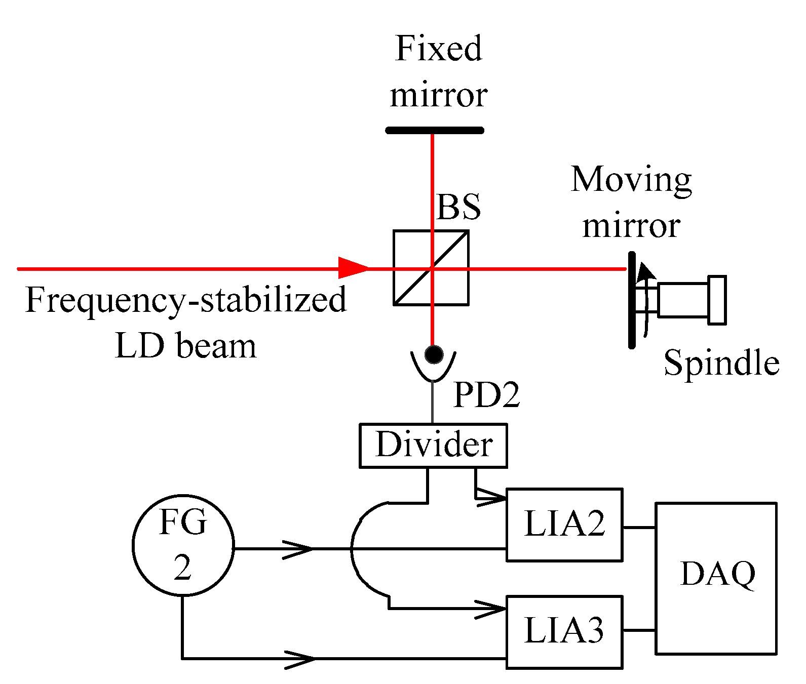
To confirm the measurement accuracy and resolution, the interferometer was used to measure the displacement of a mirror, which was generated by a piezoelectric transducer (PZT); see Figure 1. Concurrently, the displacement of the mirror was measured using a capacitive sensor. To clarify the measurement speed, the proposed interferometer was used to measure the axial error of a high-speed spindle; see Figure 2. The experimental setup was similar to the experiment using the PZT. The moving mirror was attached on the top of a spindle instead of on the PZT. The interference signal was collected by PD2 under the presence of the vibration and the strong environmental disturbance caused by the spindle operation at 500 rpm.
3. Experiments and Results
Frequency Stabilized for LD at 1 MHz Modulation Frequency
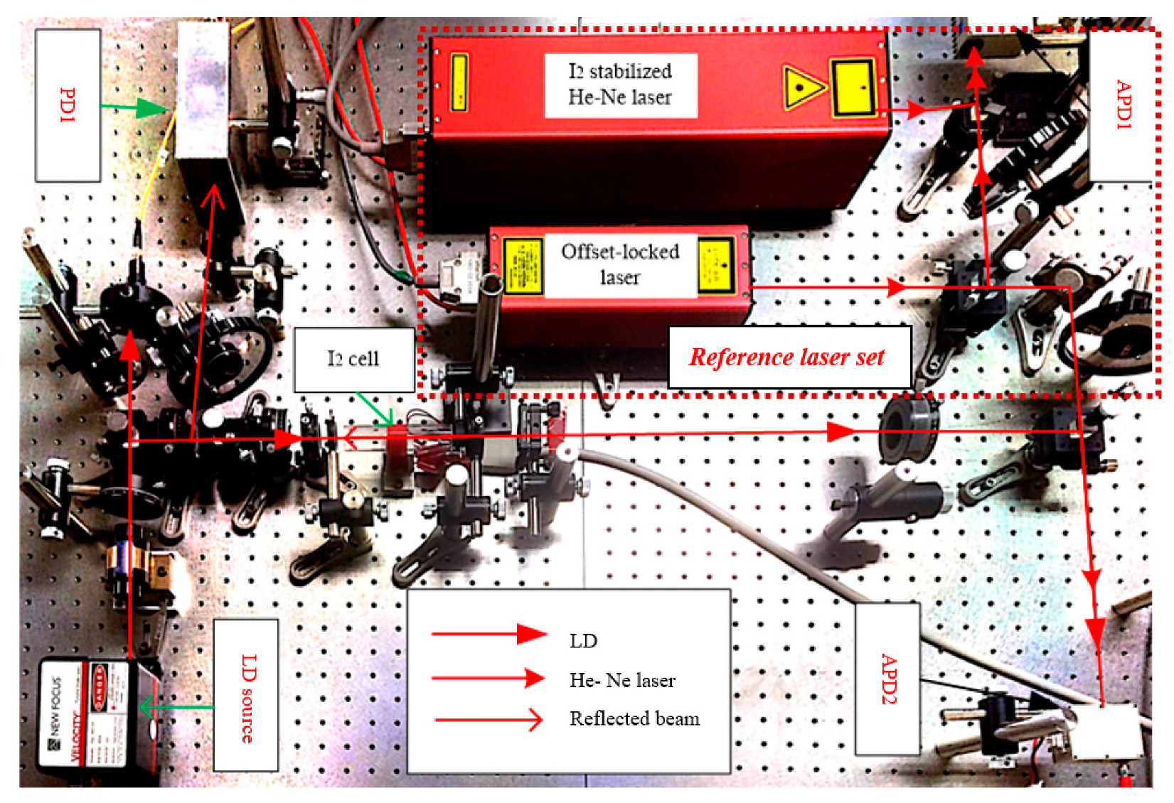
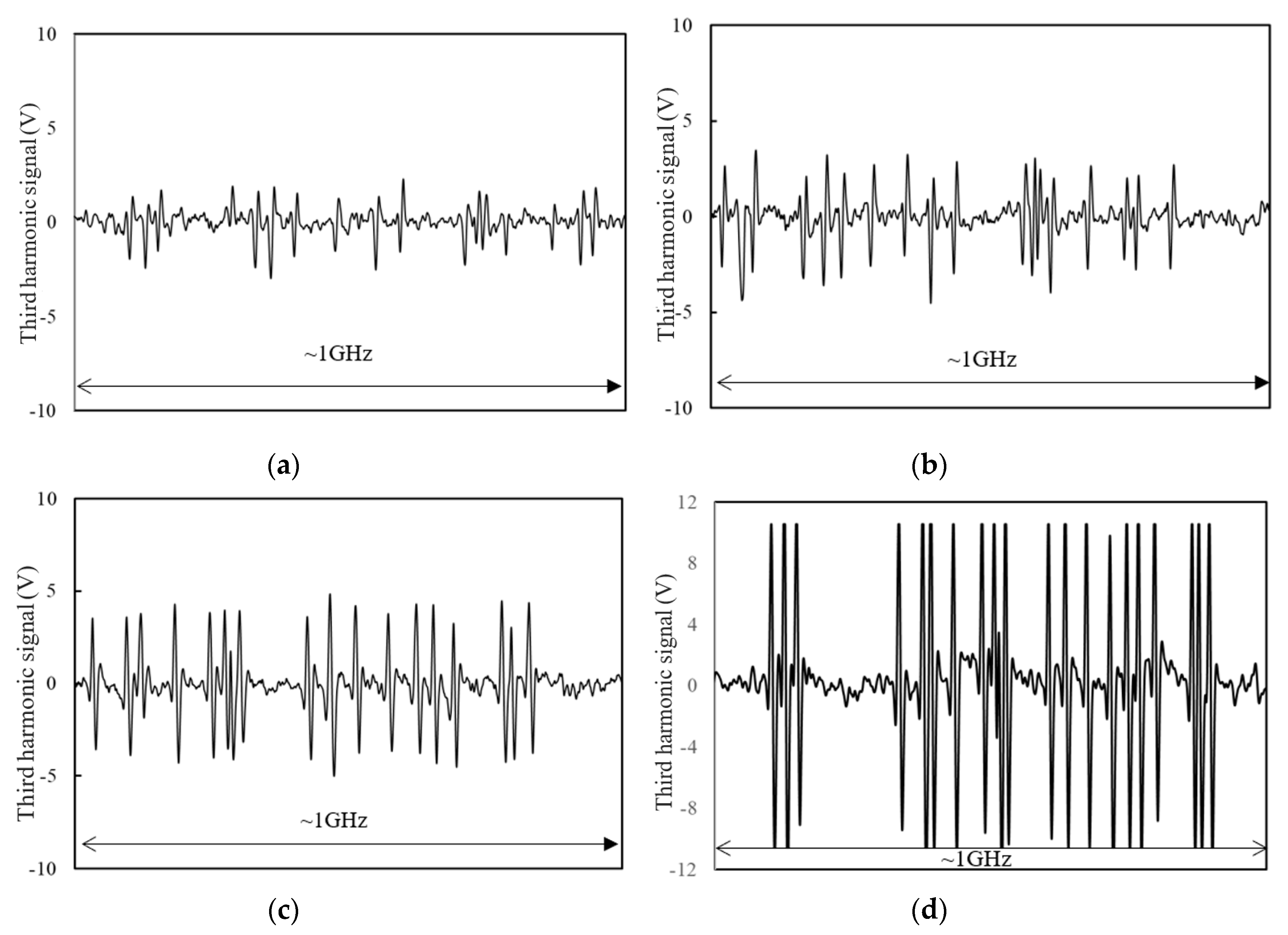
The experimental condition and the experimental setup for the locking frequency of the LD are shown in Table 1 and Figure 3, respectively. In the experiment, an LD (6304, New Focus, Irvine, California, USA) at a wavelength of 633 nm was used. The frequency of the LD was modulated by modulating the injection current at 1 MHz and scanned continuously over a range of 1 GHz to detect the hyperfine structure at the transition 6–3, P(33) of 127I2. The hyperfine structure was observed by detecting the third harmonic of the saturated absorption signals deduced by LIAs. In this research, a high bandwidth LIA up to 50 MHz was employed (HF2LI Lock-in Amplifier, Zurich Instruments, Zurich, Switzerland). The I2 cell was 100 mm long, and the cold-finger temperature of the cell was kept at 15 °C using a thermal electric cooler (TEC 3-6, Thorlabs Inc., Newton, NJ, USA). In order to obtain a high-frequency stability level for the LD, a high signal-to-noise ratio of the absorption signal was required. The absorption signal depends on the modulation frequency, the modulation excursion, and the physical parameters of the absorber cell (length, pressure, and purity) [25]. Moreover, in the interferometer, the modulation excursion also affects all the harmonic intensities depending on the modulation index. Therefore, a suitable modulation excursion was determined to enhance both the signal-to-noise ratio of the absorption signal and the harmonics intensities. The hyperfine spectrum of the transition 6–3, P(33), the b1–b21 components, was obtained by the LIA, with some values of the modulation excursion being shown in Figure 4.
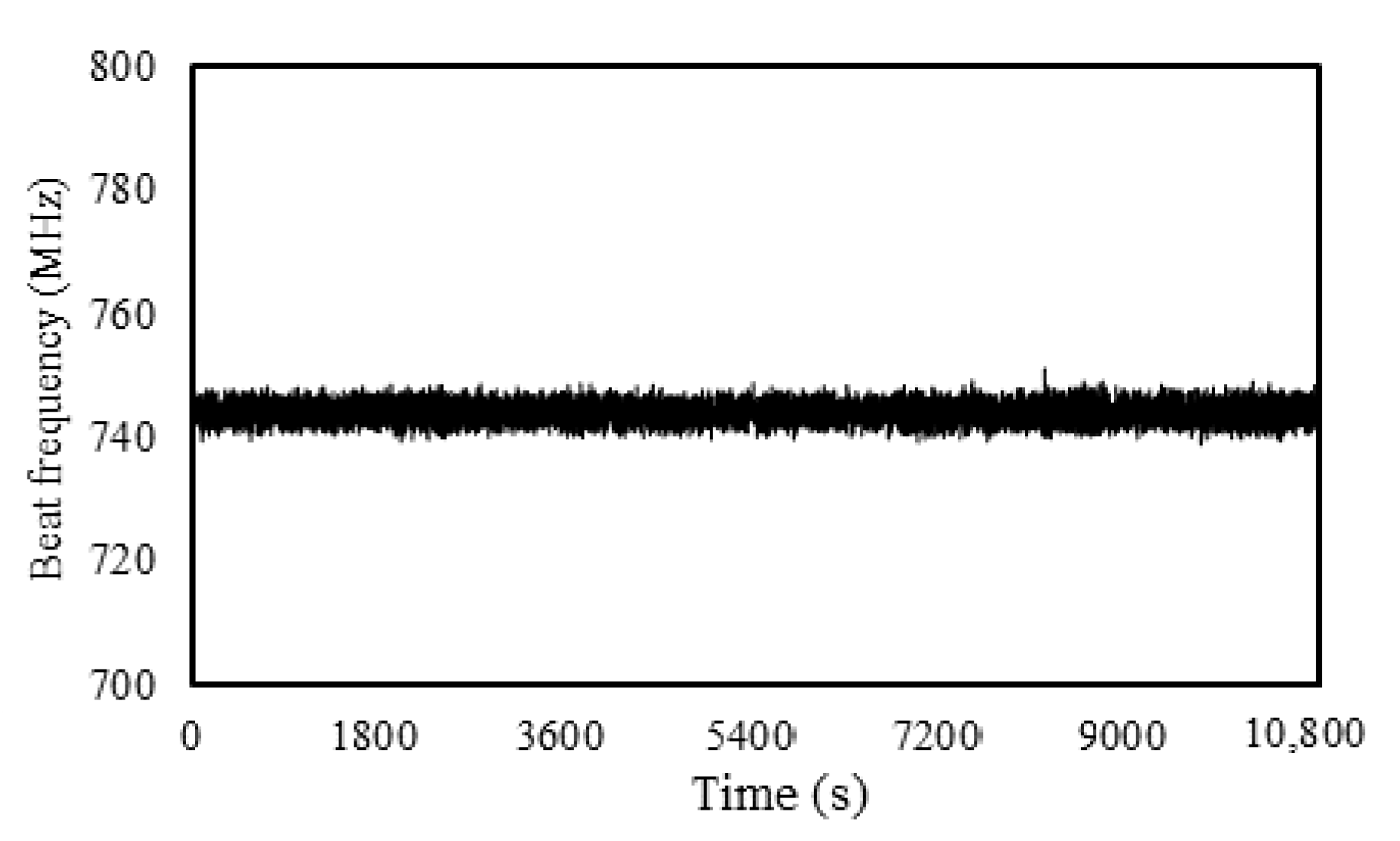
Figure 4 shows that the saturated absorption signals of the 127I2 hyperfine spectrum at the transition 6–3, P(33) can be determined purely at a modulation excurrent of 25 MHz. The absorption signal with the zero-crossing point from the LIA was used as the error signal to feed to the PID controller to lock the frequency of the LD to the b21 hyperfine component. To measure the long-term frequency stability of the stabilized LD, a beat frequency measurement with a reference laser set was performed. The set included a standardized He–Ne laser (NEO-92SI-NF, Neoark Corp, Tokyo, Japan) as a master source. The frequency of the master laser was locked to the a13 hyperfine component of the R(127), 11–5 transition of I2, which had an uncertainty of frequency of 2.5 × 10⁻¹¹. The distance between the b21 component of P(33) 6–3 and the a13 of R(127) 11–5 was over the bandwidth of the frequency counter. Therefore, an offset-locked He–Ne laser (NEO-OL101K, Neoark Corp., Tokyo, Japan) with the same level of frequency stability, but an unmodulated frequency was used as a slave laser. The avalanche detector 1 (APD1) (C5658, Hamamatsu Photonic, Hamamatsu, Japan) was used to measure the beat frequency between the master and the slaver laser to ensure that the reference laser set was operated in the true condition. In this experiment, an offset frequency of 400 MHz was used for the slave laser. The beat signal between the LD and the reference laser set was collected using the APD2 (C5658, Hamamatsu Photonic, Hamamatsu, Japan). The frequency fluctuation (peak-to-peak) in 3 h was less than 4 MHz (Figure 5). The frequency stability of the locked LD was much higher than the normal LDs, whose frequency fluctuation is sometimes at the GHz level for 1 h.
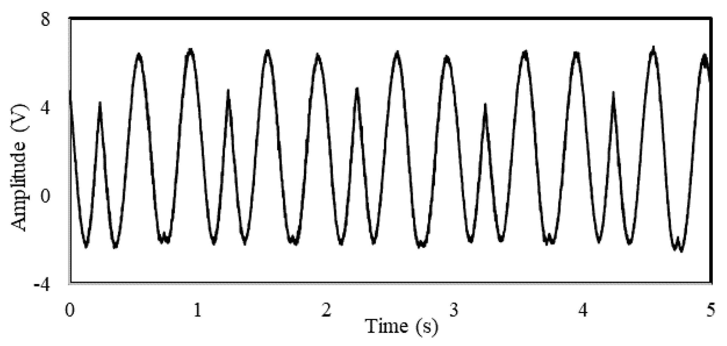
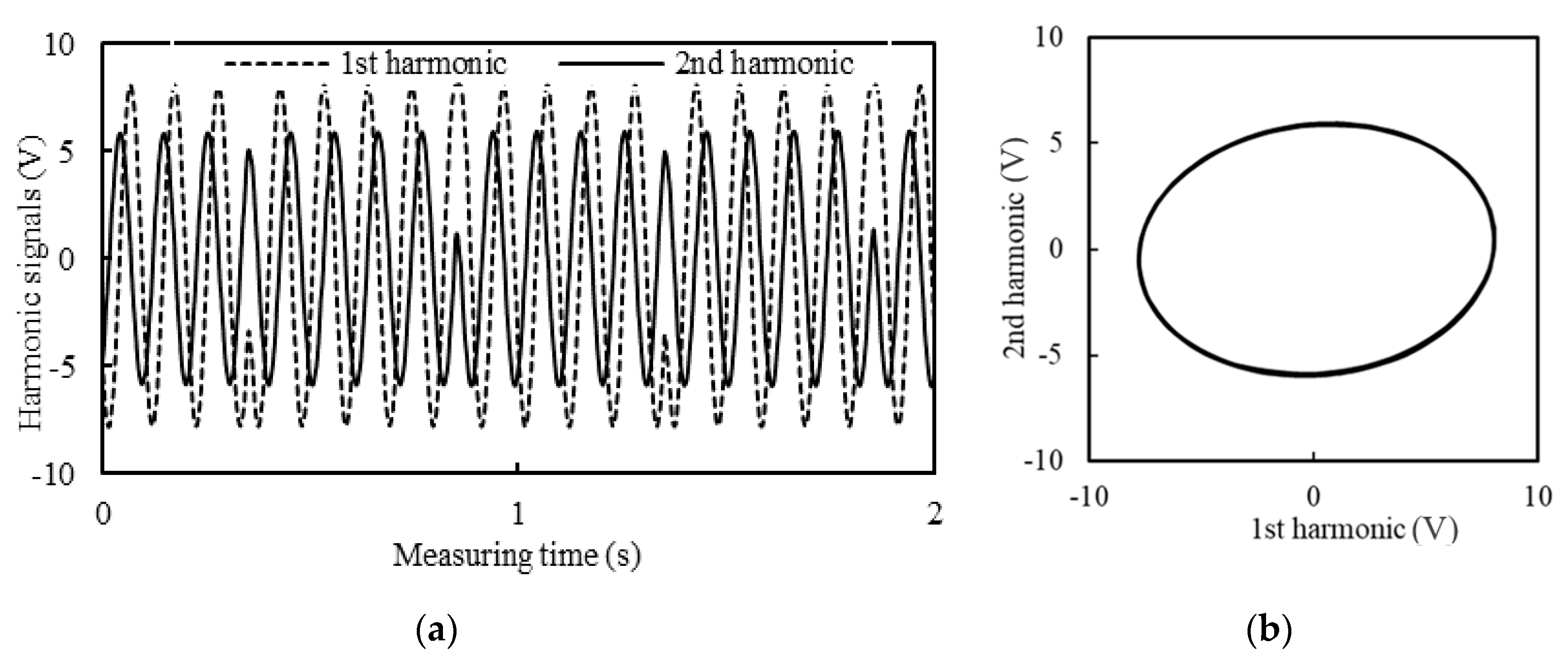
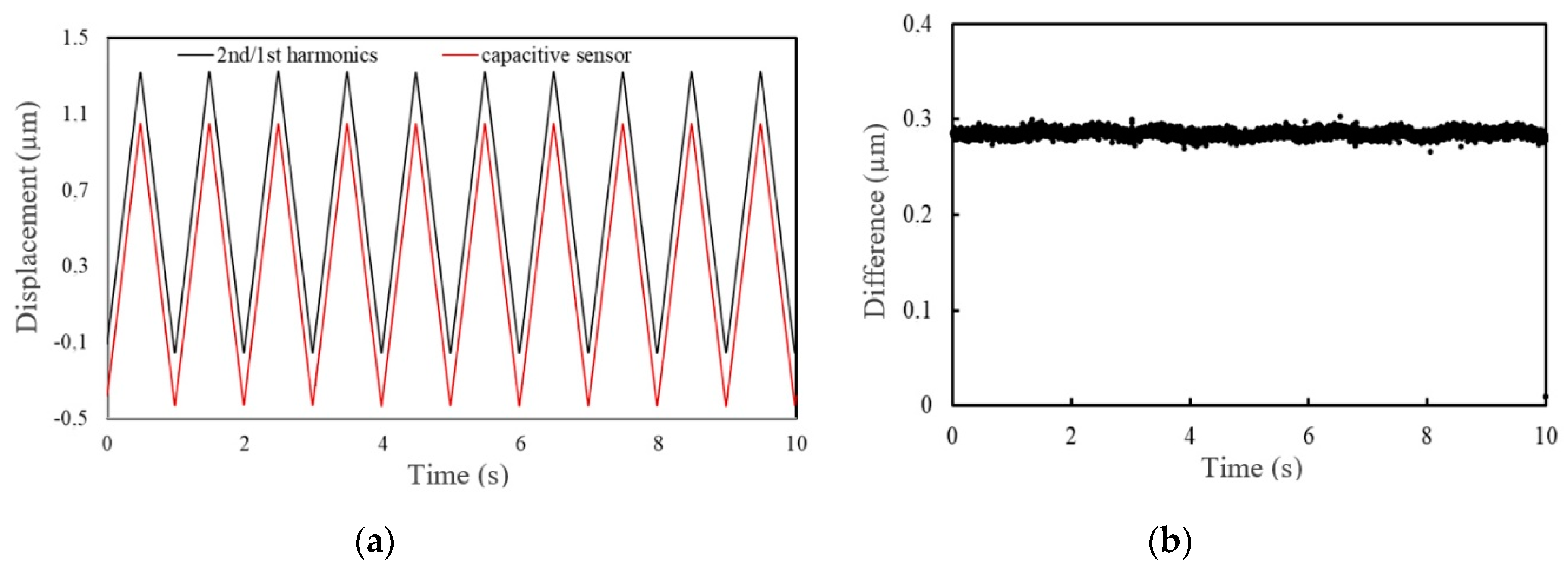
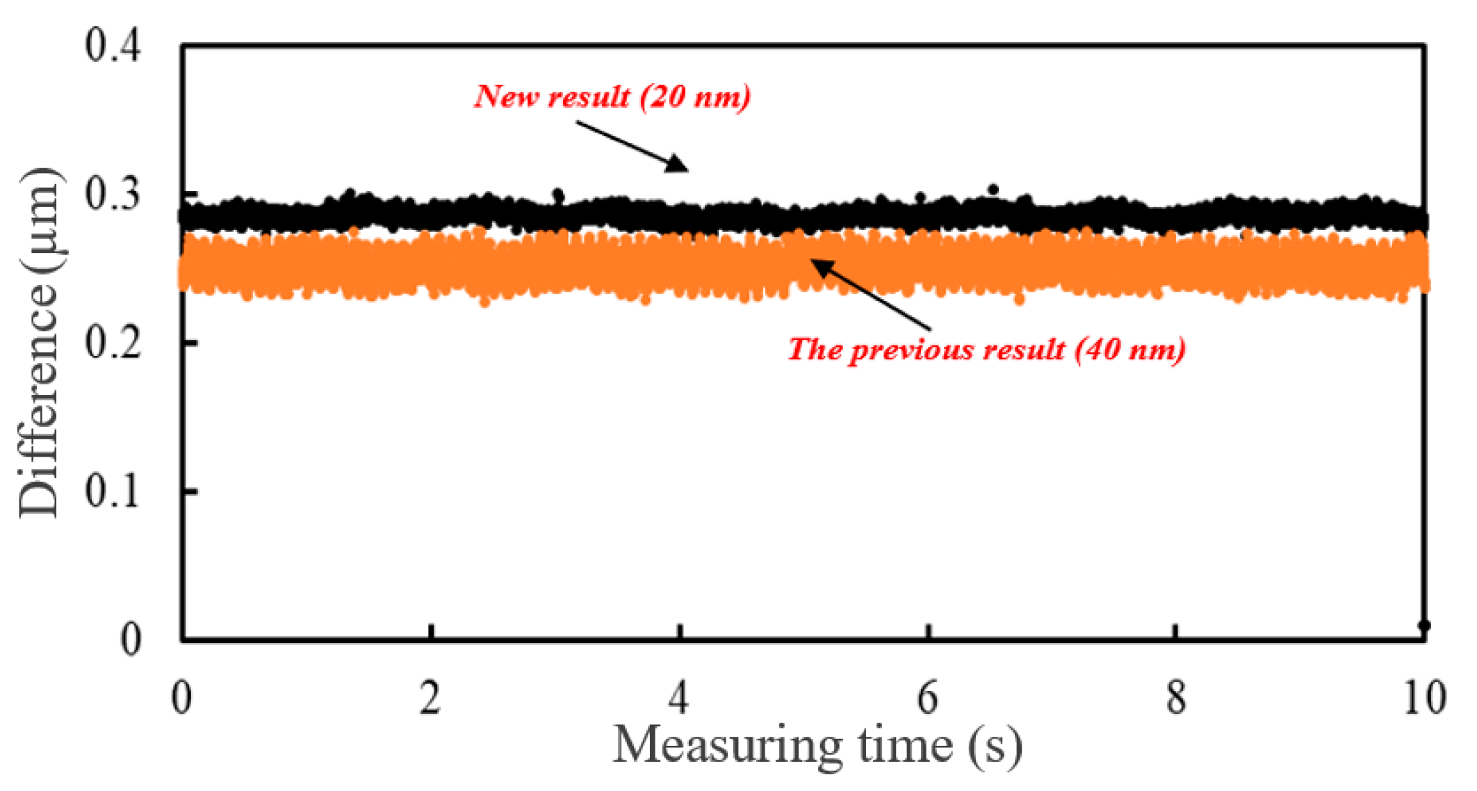
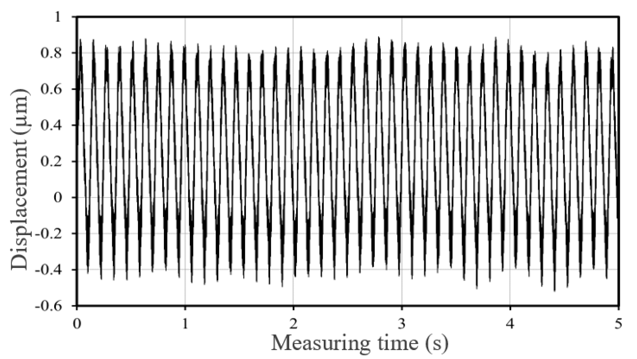
The frequency-locked LD was then used for the Michelson interferometer to measure the displacement. In order to verify the improvement of the new system with our previous one [14], the triangular form of displacement was generated using the same PZT (P750.20, Physik Instrumente, Karlsruhe, Germany). The conditions of the new and old experiment are shown in Table 2 in the new experiment and old experiment column, respectively. The interference signal of the new system is shown in Figure 6. The phase shift deduced from the displacement of the target mirror was measured using the first and second harmonics of the interference signal. In our previous work, there was some noise that could be seen from the harmonic signals [13,14]; hence, the measurement accuracy was reduced. In this experiment, the digital LIA (HF2LI, Zurich Instruments, Zurich, Switzerland) was employed to detect the first and second harmonics (Figure 7a). A Lissajous diagram showing the movement direction using these harmonics is shown in Figure 7b. To determine the measurement resolution, the displacement of the target mirror was simultaneously measured by both the interferometer and a capacitive sensor (Micro Sense Model 4083 with Probe Model 2806 L, MicroSense, Lowell, MA, USA). The capacitive sensor can operate in a range of ±10 μm and at a measurement resolution of 0.7 nm. The displacement measurement results are shown in Figure 8a. A small shift in the displacement results in the vertical direction can be seen in the figure. This shift was induced by the air gap between the probe of the capacitive sensor and the target mirror and the initial phase of the interferometer. However, a PZT displacement of 1.5 μm and a period of 1 s were successfully measured using the interferometer. The difference in the displacement-measuring results between the proposed interferometer and the capacitive sensor is shown in Figure 8b. A difference of about 20 nm due to environmental disturbance can be seen in the figure. A comparison of the difference between the new system and our previous one (see Figure 8d [14]) is shown in Figure 9. The difference in the displacement measuring result using the new system was less than a half of the previous result.
In order to verify the performance of the interferometer at a higher measurement speed, the interferometer was employed to measure the axial error of a spindle. The spindle (Chuo Precision Industry Co., Tokyo, Japan.) was driven at a velocity of 500 rpm. The axial error of the spindle was measured using the first and second harmonics. An axial error of about 1.3 µm was measured, as shown in Figure 10. The interferometer could operate stably, even though vibration and air disturbance were present.
4. Conclusions
In this work, the displacement measurement interferometer based on I2-frequency-stabilized LD was established. A high modulation frequency at 1 MHz by modulating the injection current was applied to the LD. The frequency of the LD was successfully locked to the b21 hyperfine component of the transition 6–3, P(33) of I2. The frequency peak-to-peak fluctuation of the stabilized LD was 4 MHz in 3 h. The modulation excursion was determined to improve the signal-to-noise ratio of both the I2 absorption signal and the harmonic intensities. The difference in the displacement measurement result between the proposed interferometer and the capacitive sensor was 20 nm. It was reduced by half compared with our previous system. Moreover, the interferometer was used to measure the axial error of a spindle at 500 rpm. The interferometer could measure accurately even in the presence of air disturbance and vibration caused by the spindle operation. For future work, the proposed interferometer should be compared with a heterodyne interferometer to clarify clearly the measurement accuracy and measurement speed. Besides, we might also expect that the measurement speed of our interferometer could exceed the limitation speed of a heterodyne interferometer (~5 m/s) by using a modulation frequency of 40 MHz for the LD (see Equation (6)).
Author Contributions
Supervision: T.T.V. (Toan Thang Vu); conceptualization: T.T.V. (Thanh Tung Vu) and N.T.B.; methodology: T.T.V. (Thanh Tung Vu) and H.H.H.; software: H.H.H.; validation: T.T.V. (Toan Thang Vu) and T.T.V. (Thanh Tung Vu); investigation: T.T.V. (Thanh Tung Vu); resources: H.H.H. and T.T.V. (Toan Thang Vu); writing, original draft preparation: T.T.V. (Thanh Tung Vu) and H.H.H.; writing, review and editing: N.T.B.; project administration: T.T.V. (Thanh Tung Vu); funding acquisition: T.T.V. (Toan Thang Vu). All authors read and agreed to the published version of the manuscript.
Funding
This work was funded by the Vietnam Ministry of Education and Training under Project Number B2018-BKA-07 CTrVL.
Conflicts of Interest
The authors declare that there is no conflict of interest.
References
- Pogačnik, A.; Požar, T.; Kalin, M.; Možina, J. A homodyne quadrature laser interferometer for micro-asperity deformation analysis. Sensors 2013, 13, 703–720. [Google Scholar] [CrossRef] [PubMed] [Green Version]
- Cui, J.; He, Z.; Jiu, Y.; Tan, J.; Sun, T. Homodyne laser interferometer involving minimal quadrature phase error to obtain subnanometer nonlinearity. Appl. Opt. 2016, 55, 7086–7092. [Google Scholar] [CrossRef] [PubMed]
- Köchert, P.; Flügge, J.; Weichert, C.; Köning, R.; Manske, E. Phase measurement of various commercial heterodyne He–Ne-laser interferometers with stability in the picometer regime. Meas. Sci. Technol. 2012, 23, 074005. [Google Scholar] [CrossRef]
- Yan, H.; Duan, H.Z.; Li, L.T.; Liang, Y.R.; Luo, J.; Yeh, H.C. A dual-heterodyne laser interferometer for simultaneous measurement of linear and angular displacements. Rev. Sci. Instrum. 2015, 86, 123102. [Google Scholar] [CrossRef] [PubMed] [Green Version]
- Brand, U. Frequency stabilization of a He–Ne laser at 543.5 nm wavelength using frequency-modulation spectroscopy. Opt. Commun. 1993, 100, 361–373. [Google Scholar] [CrossRef]
- Nomura, J.; Yoshii, K.; Hisai, Y.; Hong, F.L. Precision spectroscopy and frequency stabilization using coin-sized laser modules. J. Opt. Soc. Am. B 2019, 36, 631–637. [Google Scholar] [CrossRef]
- Ikeda, K.; Okubo, S.; Wada, M.; Kashiwagi, K.; Yoshii, K.; Inaba, H.; Hong, F.L. Iodine-stabilized laser at telecom wavelength using dual-pitch periodically poled lithium niobate waveguide. Opt. Express 2020, 8, 2166–2178. [Google Scholar] [CrossRef]
- Lawall, L.; Kessler, E. Michelson interferometry with 10 pm accuracy. Rev. Sci. Instrum. 2000, 71, 2669–2676. [Google Scholar] [CrossRef]
- Pisani, M. Multiple reflection Michelson interferometer with picometer resolution. Opt. Express 2008, 16, 21558–21563. [Google Scholar] [CrossRef]
- Zhang, E.; Chen, B.; Zheng, H.; Teng, X. Laser heterodyne interference signal processing method based on phase shift of reference signal. Opt. Express 2018, 26, 8656–8668. [Google Scholar] [CrossRef]
- Demarest, F.C. High-resolution, high-speed, low data age uncertainty, heterodyne displacement measuring interferometer electronics. Meas. Sci. Technol. 1998, 9, 1024. [Google Scholar]
- Nguyen, T.D.; Duong, Q.A.; Higuchi, M.; Vu, T.T.; Wei, D.; Aketagawa, M. 19-picometer mechanical step displacement measurement using heterodyne interferometer with phase-locked loop and piezoelectric driving flexure-stage. Sens. Actuators A Phys. 2020, 304, 111880. [Google Scholar] [CrossRef]
- Vu, T.T.; Maeda, Y.; Aketagawa, M. Sinusoidal frequency modulation on laser diode for frequency stabilization and displacement measurement. Measurement 2016, 94, 927–933. [Google Scholar] [CrossRef]
- Vu, T.T.; Higuchi, M.; Aketagawa, M. Accurate displacement-measuring interferometer with wide range using an I2 frequency-stabilized laser diode based on sinusoidal frequency modulation. Meas. Sci. Technol. 2016, 27, 105201. [Google Scholar] [CrossRef]
- Zhang, X.; Tao, Z.; Zhu, C.; Hong, Y.; Zhuang, W.; Chen, J. An all-optical locking of a semiconductor laser to the atomic resonance line with 1 MHz accuracy. Opt. Express. 2013, 21, 28010–28018. [Google Scholar] [CrossRef]
- Cheng, W.Y.; Shy, J.T.; Lin, T. A compact iodine-stabilized HeNe laser and crossover resonances at 543 nm. Optics communications. Opt. Commun. 1998, 156, 170–177. [Google Scholar] [CrossRef]
- Talvitie, H.; Merimaa, M.; Ikonen, E. Frequency stabilization of a diode laser to Doppler-free spectrum of molecular iodine at 633 nm. Opt. Commun. 1998, 152, 182–188. [Google Scholar] [CrossRef]
- Fang, H.M.; Wang, S.C.; Shy, J.T. Frequency stabilization of an external cavity diode laser to molecular iodine at 657.483 nm. Appl. Opt. 2006, 45, 3173–3176. [Google Scholar] [CrossRef]
- Cheng, W.Y.; Shy, J.T. Wavelength standard at 543 nm and the corresponding 127 I2 hyperfine transitions. JOSA B 2001, 18, 363–369. [Google Scholar] [CrossRef]
- Sathian, J.; Jaatinen, E. Intensity dependent residual amplitude modulation in electro-optic phase modulators. Appl. Opt. 2012, 51, 3684–3691. [Google Scholar] [CrossRef] [PubMed]
- Bi, J.; Zhi, Y.; Li, L.; Chen, L. Suppressing residual amplitude modulation to the 10− 7 level in optical phase modulation. Appl. Opt. 2019, 58, 690–694. [Google Scholar] [CrossRef] [PubMed]
- Liu, F.; Wang, C.; Li, L.; Chen, L. Long-term and wideband laser intensity stabilization with an electro-optic amplitude modulator. Opt. Laser Technol. 2013, 45, 775–781. [Google Scholar] [CrossRef]
- Duong, Q.A.; Nguyen, T.D.; Vu, T.T.; Higuchi, M.; Wei, D.; Aketagawa, M. Suppression of residual amplitude modulation appeared in commercial electro-optic modulator to improve iodine-frequency-stabilized laser diode using frequency modulation spectroscopy. J. Eur. Opt. Soc. Rapid. Publ. 2018, 14, 25. [Google Scholar] [CrossRef] [Green Version]
- Xia, W.; Liu, Q.; Hao, H.; Guo, D.; Wang, M.; Chen, X. Sinusoidal phase-modulating self-mixing interferometer with nanometer resolution and improved measurement velocity range. Appl. Opt. 2015, 54, 7820–7827. [Google Scholar] [CrossRef] [PubMed]
- Lazar, J.; Hrabina, J.; Jedlička, P.; Číp, O. Absolute frequency shifts of iodine cells for laser stabilization. Metrologia 2009, 46, 450. [Google Scholar] [CrossRef]
Figure 1.
Frequency-locked displacement-measuring interferometer. LD: laser diode; OI: optical isolator; HWP: half-wave plate; PBS: polarized beam splitter; BS: beam splitter; PD: photodetector; QWP: quarter-wave plate; PZT: piezoelectric transducer; LIA: lock-in amplifier; TEC: thermal electric cooler; PID: proportional–integral–derivative controller; FG: function generator; DAQ: data acquisition.

Figure 2.
Axial error of a high-speed spindle measuring system. PD: photodetector; LIA: lock-in amplifier; FG: function generator; DAQ: data acquisition.
Figure 2.
Axial error of a high-speed spindle measuring system. PD: photodetector; LIA: lock-in amplifier; FG: function generator; DAQ: data acquisition.

Figure 3.
Experimental setup of the frequency-stabilized LD system. LD: laser diode; PD: photodetector; APD: avalanche detector.
Figure 3.
Experimental setup of the frequency-stabilized LD system. LD: laser diode; PD: photodetector; APD: avalanche detector.

Figure 4.
Hyperfine spectrum of the transition 6–3, P(33) of 127I2 obtained by third-harmonic detection with a modulation frequency of 1 MHz: (a) a modulation excursion of 10 MHz; (b) a modulation excursion of 15 MHz; (c) a modulation excursion of 20 MHz; (d) a modulation excursion of 25 MHz.
Figure 4.
Hyperfine spectrum of the transition 6–3, P(33) of 127I2 obtained by third-harmonic detection with a modulation frequency of 1 MHz: (a) a modulation excursion of 10 MHz; (b) a modulation excursion of 15 MHz; (c) a modulation excursion of 20 MHz; (d) a modulation excursion of 25 MHz.

Figure 5.
Frequency stability of the locked LD for 3 h.

Figure 6.
Interference signal of the displacement-measuring interferometer.

Figure 7.
First and second harmonics detected by the lock-in amplifiers (LIAs) (a) and illustrated in a Lissajous diagram (b).
Figure 7.
First and second harmonics detected by the lock-in amplifiers (LIAs) (a) and illustrated in a Lissajous diagram (b).

Figure 8.
Displacement-measuring result: (a) the displacement-measuring result using the interferometer (black line) and the capacitive sensor (red line); (b) the displacement difference between the interferometer and the capacitive sensor.
Figure 8.
Displacement-measuring result: (a) the displacement-measuring result using the interferometer (black line) and the capacitive sensor (red line); (b) the displacement difference between the interferometer and the capacitive sensor.

Figure 9.
The difference in the displacement measuring result between the new system and our previous one.
Figure 9.
The difference in the displacement measuring result between the new system and our previous one.

Figure 10.
Axial error measurement of a spindle at a 500 rpm rotation speed.


Table 1.
Experimental conditions of the locking frequency of the laser diode (LD).
| Laser source | 6304 |
| Wavelength | 632–634 nm |
| Modulation frequency for LD | 1 MHz |
| Modulation amplitude for LD | 25 MHz |
| Temperature of cold finger | 15 ± 0.1 °C |
| Temperature; pressure; humidity | 20 ± 0.1 °C; 1013 ± 0.02 kPa; 33 ± 0.01 RH |
Table 2.
Experimental conditions of the displacement measurements.
| New System | Old System | |
|---|---|---|
| Operating frequency of PZT (Hz) | 1 | 1 |
| Amplitude of PZT stage (μm) | 1.5 | 1.5 |
| Modulation frequency for LD (kHz) | 1000 | 300 |
| Cut-off frequency of low pass filters (kHz) | 900 | 100 |
| Measuring time (s) | 10 s | 10 s |
© 2020 by the authors. Licensee MDPI, Basel, Switzerland. This article is an open access article distributed under the terms and conditions of the Creative Commons Attribution (CC BY) license (http://creativecommons.org/licenses/by/4.0/).
Share and Cite
MDPI and ACS Style
Vu, T.T.; Hoang, H.H.; Vu, T.T.; Bui, N.T. A Displacement Measuring Interferometer Based on a Frequency-Locked Laser Diode with High Modulation Frequency. Appl. Sci. 2020, 10, 2693. https://0-doi-org.brum.beds.ac.uk/10.3390/app10082693
AMA Style
Vu TT, Hoang HH, Vu TT, Bui NT. A Displacement Measuring Interferometer Based on a Frequency-Locked Laser Diode with High Modulation Frequency. Applied Sciences. 2020; 10(8):2693. https://0-doi-org.brum.beds.ac.uk/10.3390/app10082693
Chicago/Turabian StyleVu, Thanh Tung, Hong Hai Hoang, Toan Thang Vu, and Ngoc Tam Bui. 2020. "A Displacement Measuring Interferometer Based on a Frequency-Locked Laser Diode with High Modulation Frequency" Applied Sciences 10, no. 8: 2693. https://0-doi-org.brum.beds.ac.uk/10.3390/app10082693
Note that from the first issue of 2016, this journal uses article numbers instead of page numbers. See further details here.