Influence of Structural Configurations on the Shear Fatigue Damage of the Blade Trailing-Edge Adhesive Joint


Jiangsu Key Laboratory of Hi-Tech Research for Wind Turbine Design, Nanjing University of Aeronautics and Astronautics, Nanjing 210016, China
*
Author to whom correspondence should be addressed.
Appl. Sci. 2020, 10(8), 2715; https://0-doi-org.brum.beds.ac.uk/10.3390/app10082715
Submission received: 13 March 2020
/
Revised: 12 April 2020
/
Accepted: 12 April 2020
/
Published: 15 April 2020
(This article belongs to the Special Issue Wind Power Technologies)
Abstract
:Wind turbines are under continuous development for large-scale deployment and oceanization, leading to the requirement of longer blades. The economic losses caused by blade replacement and shutdown have increased. The downtime caused by blade issues in a wind turbine is 8–20% of the total downtime. Many of these blade issues originate from the cracking of the blade trailing edge. The edge is more susceptible to damage due to the complex geometry, manufacturing technique, and operation conditions. The traditional design method and the expensive experimental research are not suitable for the accurate damage analysis of the trailing-edge adhesive because of simplifying assumptions and costs. This study aimed to investigate the influence of trailing-edge structural configurations on the shear fatigue life of the trailing-edge adhesive joint using finite element and stress transformation matrix (STM) methods. The structural configurations of the blade trailing edge included the position of unidirectional fiber layer (UD), chamfer of bonding line, prefabricated components, and outer over-lamination of the trailing edge. In this study, the finite element method was used to simulate the blade structure. The shell element was used for laminates, and the solid element was used for the trailing-edge adhesive joint. The basic shear fatigue properties of the adhesive were obtained by standard component tests. The shear fatigue life of the blade trailing-edge adhesive joint under given load conditions was calculated using the fatigue properties of the adhesive and STM method. The results showed that the angle of chamfering, location of UD, rigidity of the preform, and outer over-lamination all had an obvious influence on the fatigue damage of trailing-edge adhesive. The findings of this study can be used to guide blade structure design and blade production and maintenance.
1. Introduction
At present, wind turbines are under continuous development for large-scale deployment and oceanization. Blade lengths of more than 100 m and turbines of more than 12 MW were available on the market in 2018 [1]. However, wind turbine blades had increased failure rates or decreased reliability as simple designs with small rotor diameters progressed to more advanced technologies with bigger rotor spans [2].
Factors such as cost and reliability should be considered in the design of longer and lighter blades. First, the lengthening of blades increases the cost of the wind turbine itself. In addition, the cost of blade replacement and the shutdown caused by blade damage also increase. In 2013, Sheng [3] reported that the downtime caused by blade damage accounted for 8–20% of the total downtime, second only to the downtime caused by gearbox problems. About 2% of the blades need to be replaced in their first 10 years of lifetime. In 2013, Sabbah [4] investigated 81 blades of 100 kW wind turbines and 18 blades of 300 kW turbines, with the working life ranging between 6.5 × 10⁷ and 1.1 × 10⁸ cycles, and proposed that the geometrical form and the manufacturing technique made the trailing edge of the wind turbine blade more susceptible to damage. In 2015, Wittrup [5] announced that all rotor blades at the Horns Rev2 wind farm in Denmark would be replaced. Most of the observed damage was related to leading- and trailing-edge issues. Consequently, the understanding of the structural behavior of blade trailing edge, especially the damage of trailing edge under fatigue load, needs to be improved. Research on structural problems can improve blade design and service life, thus providing a great cost-saving potential for blade manufacturers and operators. However, not many previous studies were devoted to the study of the adhesive joint failure of wind turbine rotor blades.
Glass/Carbon fiber–reinforced plastics have been widely used in the manufacture of large wind turbine blades due to its lightweight and high performance [6,7]. For most wind turbines, the composite blades are usually manufactured in parts and then bonded with adhesives in the mold (Figure 1). This bonding is of two main types. One of them is T-joint bonding for web and shell. The failure of T-joints has been explored theoretically and experimentally from different points of view by many investigators [8,9,10,11,12,13,14,15]. Wang [16] studied the damage of T-joints using finite element simulation of a realistic part of the blade structure. The results of fatigue simulation were compared with the experimental results of a previous study [17]. Another type of bonding is the lap bonding used to bind the upper and lower shells in the leading and trailing edges, as shown in Figure 1. The maintenance inspection of wind turbine blades showed that the local debonding of the blade trailing-edge shell is a common failure mode among other types of damages [18]. The cause of trailing edge failure in wind turbine blades is complex, and detailed information on this is limited. Philipp [19] explored a new blade simulation method, in which the shell lamination of the blade was simulated by the shell element, while the adhesive of the trailing edge was simulated by the solid element; the shell and solid elements were connected by a multi-point constraint (MPC). Philipp and Martin [20] studied a comprehensive method by considering both linear and nonlinear effects and their interaction in the model and test structure.
Many achievements have been made in the research of adhesive damage analysis. In 2011, Daniel et al. [21] studied the static and fatigue crack growth of thick adhesive joints when used to join fiberglass laminates. In 2013, Yi Hua [22] investigated the mechanical properties of the adhesive joint in the carbon/epoxy wind turbine blade under the combined bending, and tensile loads were studied by the finite element method. The effects of the properties and geometric details (including fillets and defects) of the bonding material were studied based on the interlaminar stress of the bonding layer. In 2014, Ji and Han [23] used the finite element analysis method combined with fracture mechanics to study the failure of the adhesive joint of the wind turbine blade. The results of a numerical calculation based on fracture mechanics showed that, before the ultimate design state was reached, the edge of the adhesive bond line began to break and expand gradually due to a high level of shear stress. In 2016, Eder and Bitsche [18] investigated mainly the damage behavior of the blade trailing-edge adhesive joint using fracture mechanics. They proposed a method based on linear fracture mechanics, which used small-scale experimental results to predict large-scale failure.
Some experimental tests were also performed on the blade trailing edge to examine the damage of the blade trailing edge. In 2016, Haselbac [2] studied the initiation of trailing-edge failure in full-scale wind turbine blade test for the accurate failure analysis of the trailing edge. The test results and simulation analysis results were compared to select the accurate simulation analysis method. Of course, some researchers tested only the local part of the blade to study the damage of the trailing edge because of the high cost of full-scale blade testing. In 2018, Lahuerta [24] carried out static and fatigue tests on the blade submodel to analyze the failure and damage mechanism of the blade trailing edge. Also, the test results were compared with the simulation results to modify the simulation analysis method. However, the test was expensive, and the complex dynamic fatigue load could not be accurately reproduced in the experiment.
In the traditional methods of adhesive fatigue analysis, such as design guidelines [25], the variable-amplitude load can be converted into a constant-amplitude load by the damage equivalent method under certain assumptions. For a given constant-amplitude dynamic load, the previous methods can be used to accurately analyze the fatigue damage of the blade trailing-edge adhesive. However, the wind turbine load is irregular. If, similar to the traditional design method, the variable-amplitude load is converted into a constant-amplitude load for analysis, it may lead to the inaccuracy caused by load simplification.
When analyzing the fatigue damage of the structural adhesive under a dynamic fatigue load, the finite element method combined with the stress transformation matrix method (FEM-STM method) [26] can be used to achieve the stress state of the adhesive with time without simplifying the dynamic fatigue load. The purpose of this study was to examine the influence of trailing-edge configuration on shear fatigue life of trailing-edge bonding using the FEM-STM method. The trailing edge had four main structural configurations: the position of unidirectional fiber layer (UD), chamfer of bonding line, prefabricated components, and outer over-lamination of the trailing edge. The combination of shell and solid elements was used to build the blade models of various configurations. The shell element simulated the laminated plate of the shell, and the solid element simulated the adhesive of the trailing edge. Blades with 33% relative thickness were selected for the blade model. Many single-lap standard test specimens were produced to obtain the basic shear fatigue properties of the adhesive joint. The shear S–N curve of the adhesive was evaluated using the fatigue test equipment. The shear fatigue life of the blade trailing-edge adhesive joint was assessed using the FEM-STM method.
2. Method
2.1. Structural Configurations and Modeling Strategies
At present, the blades are made of two upper and lower shells and multiple shear webs by bonding using the most popular production technology of wind turbine blades. The thickness of the bonding area of the trailing edge is not constant due to the influence of geometric factors such as airfoils and relative thickness. Generally, bonding is of three types to ensure that the bonding thickness of the adhesive is controlled within a certain range. These bonding types are specified in Figure 2.
Type A represents a case where the shell clearance of the trailing edge is large. In this case, the prefabricated bonding flange is required to control the bonding thickness. Type C represents a case where the shell clearance of the trailing edge is very small. In this case, adjusting the positioning of components (trailing-edge UD and staggering of layers) is necessary to control the bonding thickness. The shell clearance in the trailing edge of Type B is between that of Type A and Type C. The size of the prefabricated filler and the positioning of the components need to be considered comprehensively to control the bonding thickness in Type B. Under the same bonding width, the configurations that affect the bonding structure are roughly divided into four parts, which are shown in Figure 3. The bracketed content is the abbreviation of the model classification.
- Chamfer at the beginning of bonding line (BBL)
- The position of trailing-edge UD (PUD)
- Whether there are prefabricated components or blind bonding (PC)
- Whether there is outer over-lamination at the end of bonding line (OL)
The FEM method was used to simulate the bonding structure of the trailing edge so as to investigate the influence of these four configurations on the shear fatigue damage of the adhesive. Philipp [19] used layered shell elements to simulate the shell of the blade and the solid brick element to simulate the adhesive.
A section with a chord length of 3 m and a relative thickness of 33% was selected to create the blade section model, which is shown in Figure 4.
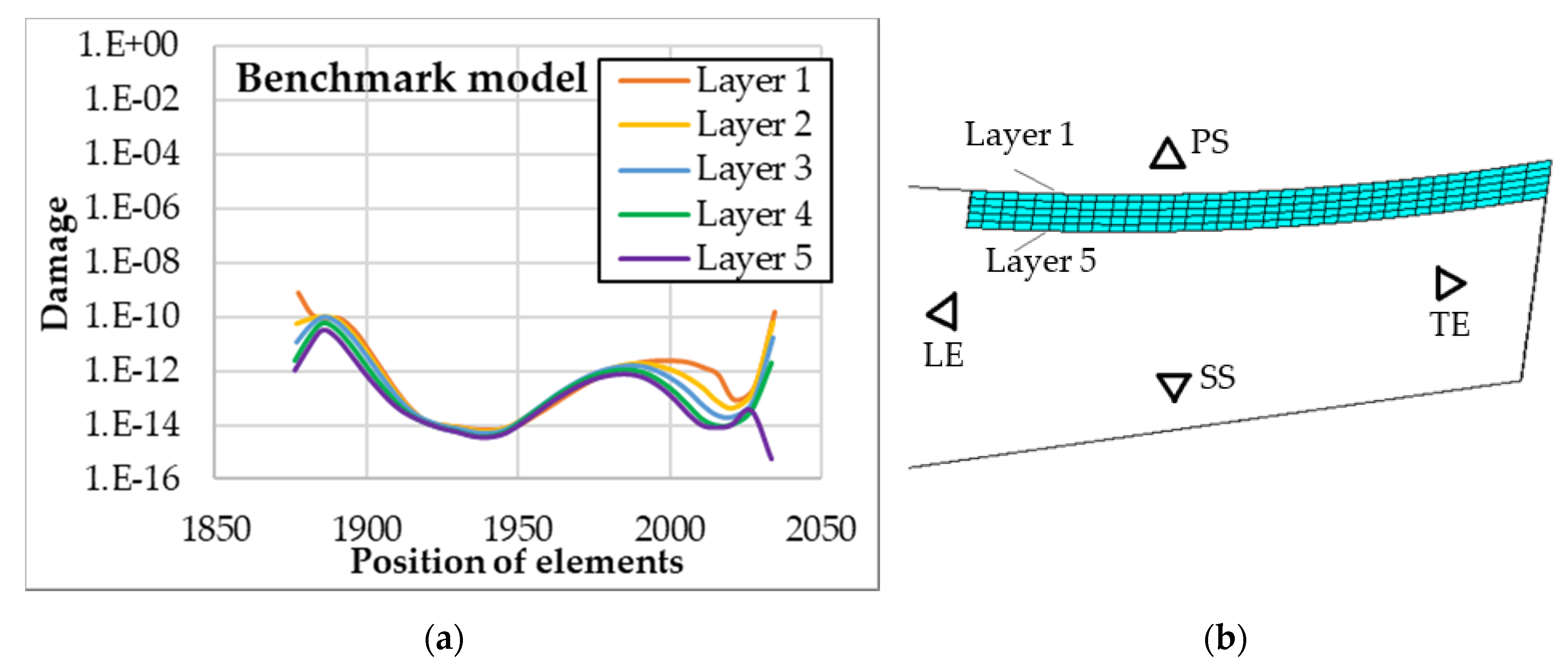
The section profile was obtained by interpolating NACA 63 series profiles. Figure 4a shows the model of the blade section and mesh in the ANSYS software package. The adhesive is divided into five layers of the solid element in the thickness direction. Figure 4b shows the shell elements, including the rendered shell thickness, while hiding the solid elements of the adhesive, prefabricated component, and outer over-lamination at the end of the bonding line.
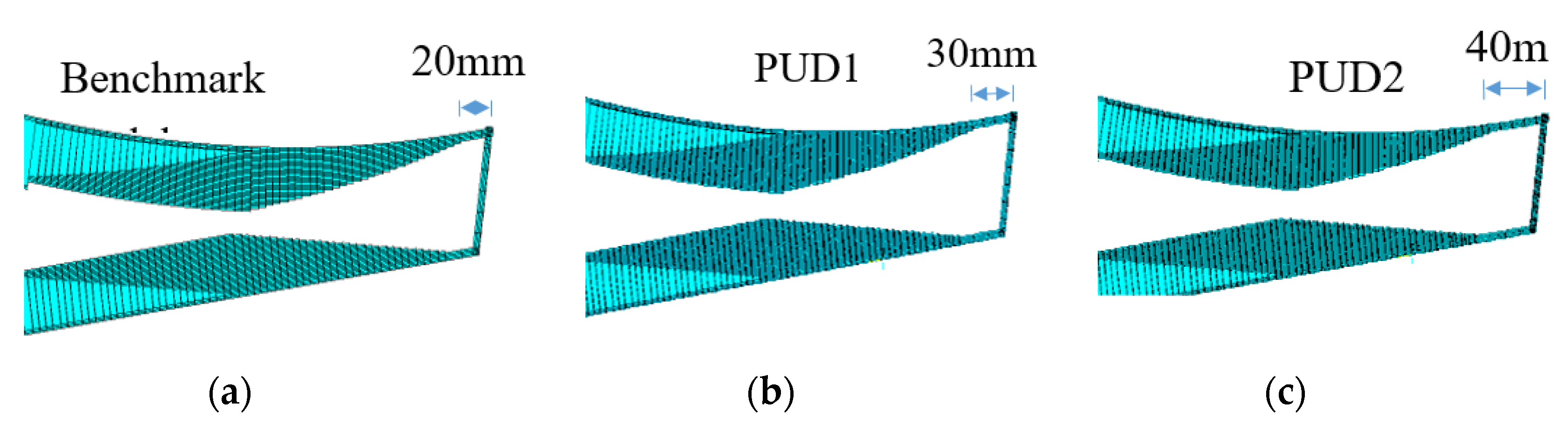
Three chamfering forms were set up to study the influence of chamfering on the shear fatigue damage of bonding, as shown in Figure 5. The influence of the prefabricated component on the adhesive shear fatigue damage was mainly considered in two cases: prefabricated flange and prefabricated filler. The effect of the outer over-lamination on shear fatigue was mainly investigated in two cases: outer over-lamination and no outer over-lamination. The distance between UD and the reference line was mainly considered to be 20, 30, and 40 mm. The average bonding width of the adhesive in all models was consistent.
2.2. Fatigue Property Test and Application
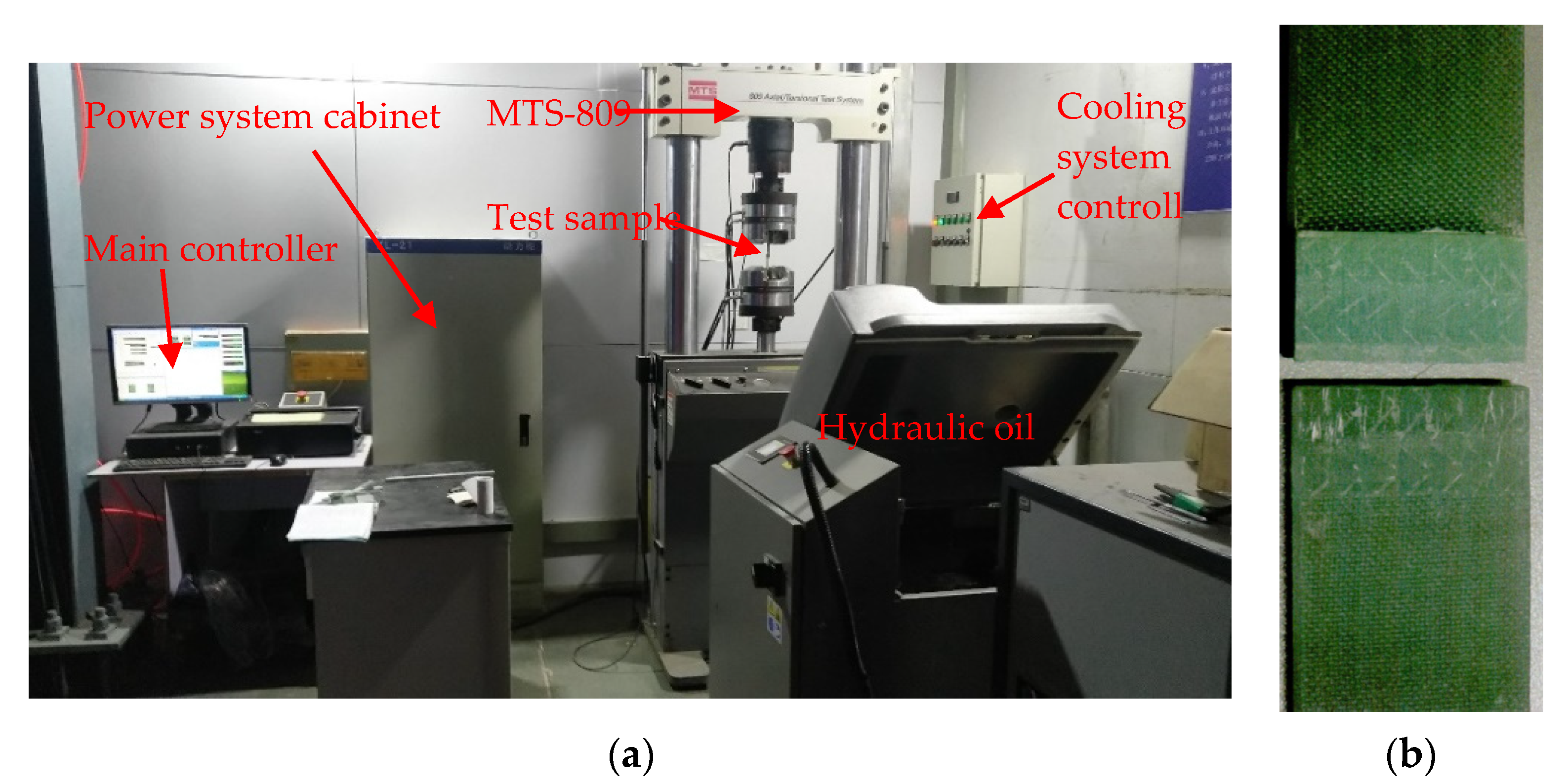
The FEM-STM method for evaluating the shear fatigue properties of trailing-edge bonding was based on the nominal stress method. A two-component adhesive, commonly used for blade adhesive 1807AB/1807AHA produced by MID (China) Ltd., was selected as the material for fatigue test to obtain the S–N curve of the shear fatigue of the adhesive. The material test was carried out according to ISO 9664:1993 [27], and the MTS-809 universal testing machine was used. Figure 6a shows the test equipment and the environment.
The maximum stress level of the test included 6, 6.3, 6.6, 6.9, 7, 8, and 10 MPa. The stress ratio was R = 0.1, and the test frequency was 30 Hz. The laboratory temperature was controlled at 23 °C ± 2 °C, and the humidity was controlled at 50% ± 5% RH. Figure 6b shows the fracture diagram of one specimen.
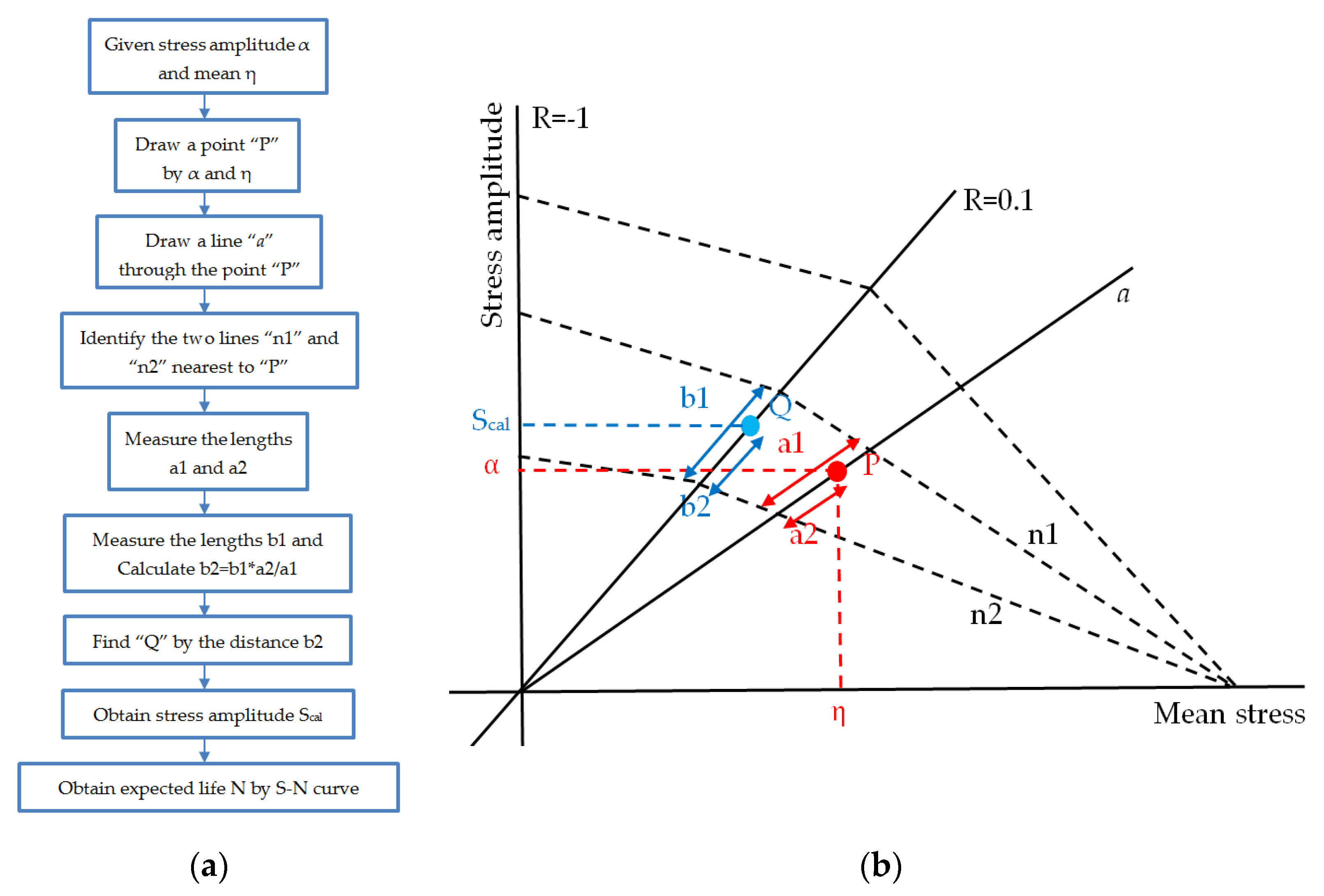
The test results were plotted in the double logarithmic coordinate system. The horizontal axis represents the number of cycles of the test, and the vertical axis represents the maximum stress of the test, as shown in Figure 7a. A constant-amplitude life diagram based on the Goodman model is shown in Figure 7b. Only the constant-amplitude life diagram with a positive stress ratio was available, as the shear stress of the adhesive did not consider the difference between positive and negative stress ratios.
After obtaining the constant-amplitude life diagram, the expected fatigue life was calculated using the diagram and the given mean value and amplitude of stress. However, the current constant-amplitude life diagram was available only for R = 0.1, as shown in Figure 7b. The fatigue life of other R values was obtained by interpolating the constant-amplitude life diagram. The interpolation method referred to DNV-OS-C501 [28], and the specific operation flow is shown in Figure 8.
2.3. FEM-STM Method
STM can be used to convert irregular blade time-series loads into time-series stresses based on the linear elasticity hypothesis. Uniform cross-section FEM models were built taking the Saint-Venant’s principle into consideration. The model and boundary conditions are shown in Figure 9. The blue line represents the MPC. The master node of MPC was located at the elastic center of the middle section of the blade segment, and the load acted on the master node. One end of the segment of the blade was connected to the slave nodes of the MPC. The boundary condition of the fixed constraint was applied to the other end of the blade segment.
2.4. Load Cases
Different wind speeds and cycle numbers should be assumed to calculate the blade fatigue damage cumulatively. The Weibull distribution was used to describe the wind speed distribution. The wind speed probability density function and cumulative distribution function could be described as follows:
If the wind speed was divided into intervals, the total hours of No. i interval in a year was as follows:
where Δ is the range of intervals.
The blade loads were calculated using the GH Bladed software based on the momentum-blade element theory widely used in aerodynamics design.
The load cases considered in the load calculation included the normal generating conditions, power production plus occurrence of the fault, startup, normal shutdown, and parked (standstill or idling). The total operating time of the load cases in 1 year should be 8760 h.
Figure 11a,b shows the moments and forces of the one load case. Under this normal generating condition, the wind speed was 6 m/s and the wind turbine had no yaw angle.
To sum up, the complete calculation process of fatigue damage of the adhesive could be described using the following flow chart (Figure 12).
3. Calculation Results and Discussion
3.1. Influence of Chamfer
The time-series stresses were obtained by multiplying the time-series loads with the STM of each node. The time-series shear stress was extracted. The fatigue damage of each node was obtained using the constant-amplitude life diagram of the material and linear damage superposition principle. A structural configuration was selected as the benchmark model to evaluate the influence of various structural configurations on shear fatigue. The structural configurations of the benchmark model are shown in Table 1.
The shear fatigue damage results of this model are shown in Figure 13. The horizontal axis represents the position of elements, arranged from the leading edge to the trailing edge, and the vertical axis represents the logarithmic expression of the damage. Figure 13 shows that the damage of the adhesive closer to the leading edge and the damage closer to the PS were more serious.
The results of other structural configurations were compared with the results of the benchmark model. The chamfered forms of each model are shown in Figure 5b–d. The model in which the angle between the chamfer surface and the bonding surface of PS was obtuse was named BBL1. The model in which the angle between the chamfer surface and the bonding surface of PS was acute was named BBL2. The main difference between BBL models and the benchmark model was the chamfered forms at the beginning of the bonding line. The other parameters were the same.
Figure 14a,b shows the damage of the BBL1 and BBL2 models, respectively. The difference between the results of the two models was reflected mainly at the beginning position of the bonding line.
Figure 15 shows a comparison of the damage distribution along the thickness of the three models at the beginning of the bonding line. BBL2 had the maximum damage and BBL1 had the least damage on the first layer. Vice versa was the case on the fifth layer. The damage near the pressure side (layer 1) and prefabricated component (layer 5) was closely related to the angle of the chamfer. If the angle of the chamfer near the bonding surface was acute, the damage increased. If the angle of the chamfer near the bonding surface was obtuse, the damage reduced.
The damage comparison results of different chamfers showed that the angle of the chamfer at the end of the bonding line should be obtuse, whether in the production or in the maintenance of blades. Generally speaking, the angle between the adhesive extruded naturally, and the bonding surface was acute when the blade mold is closed. If not treated, obvious stress concentration occurs at the bonding line, leading to high fatigue damage. One way to deal with the bonding line, which is not the only way, is to make a scraper. The scraper with a certain shape can be made before blade production and maintenance. After the completion of mold closing or bonding, the excess extrusion adhesive can be scraped away using the scraper. On the one hand, the unnecessary weight in the blade can be reduced. On the other hand, the stress concentration of the bonding line can be reduced.
3.2. Influence of the Position of UD
The structural configurations of PUD models are shown in Table 2. The main difference between PUD and benchmark models is the position of UD. The findings are shown in Figure 16. These models had the same lamination and structural configurations except the distance between UD and the end of the trailing edge. The other parameters were the same.
The damage results of PUD models are shown in Figure 16. A comparison of the results of each layer with those of the benchmark model is shown in Figure 17. As the UD moved toward the leading edge, the peak and valley of the damage in the middle region of the adhesive also moved toward the leading edge. In addition, the value of damage valley near the trailing edge appeared in the shell area without UD and became lower when UD moved toward the leading edge. The peak value of damage in the middle region appeared in the staggered layer region of UD. The position of the peak value moved with the movement of UD, but the value of damage hardly changed. Another damage valley near the leading edge appeared in the area where the total thickness of the shell was constant. The position of the valley also moved with the movement of UD, and the value of damage valley gradually increased with the movement of UD toward the leading edge.
The analysis results in Figure 18 show that the location of UD indeed affected the damage distribution of the adhesive at the trailing edge. However, adjusting the damaged distribution of the trailing-edge adhesive by adjusting the position of the trailing-edge UD in the actual blade structure design is almost impossible. First, the positioning of UD material on the trailing edge of the wind turbine blade largely determined the edge-wise stiffness of the blade. In addition, the position of the trailing-edge UD played a key role in controlling the clearance of the trailing edge. Therefore, the edge-wise stiffness and clearance were the two main considerations for UD positioning of the trailing edge in the blade structure design. The calculation results might help understand the effect of UD positioning on shear fatigue damage of the trailing-edge adhesive.
3.3. Influence of Prefabricated Component
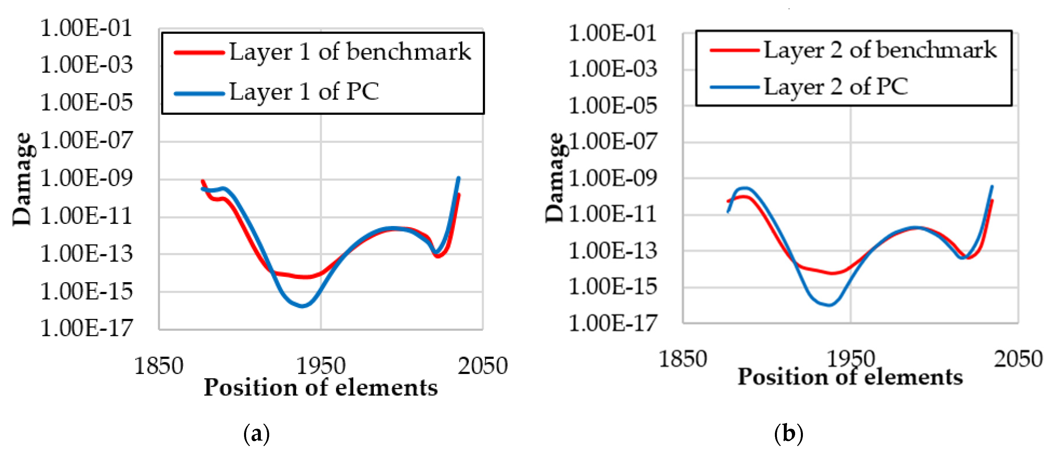
The structural configurations of the PC model are shown in Table 3. The main difference between the PC and benchmark models was that the prefabricated component of the PC model was the prefabricated flange. The other parameters were the same. The stiffness of the prefabricated filler was significantly greater than that of the prefabricated flange because the prefabricated filler consisted of the laminated plate and core, while the preformed flange consisted of only the laminated plate. Figure 19 shows the damage of the PC model and the difference between the two models.
A comparison of the results of each layer with those of the benchmark model is shown in Figure 20. When the adhesive flange with smaller stiffness was used for bonding, the values of damage of the peak and the valley were higher and lower, respectively, than those of the reference model.
The analysis results of the PC model showed that the stiffness of the prefabricated component had an obvious influence on the damage distribution of the adhesive. In blade design and maintenance, engineers always hope that the maximum damage of the adhesive will be as small as possible. Currently, it is better to use prefabricated components with larger stiffness as much as possible under allowable conditions.
3.4. Influence of Outer Over-Lamination
The structural configurations of the OL model are shown in Table 4. The main difference between the PC and benchmark models was the lack of outer over-lamination in the OL model. The OL model removed the laminate element at the end of the bonding line to simulate the case with no outer over-lamination. Figure 21 shows the damage of the OL model.
A comparison of the results of each layer with those of the benchmark model is shown in Figure 22. The damage without outer over-lamination was much higher than that with outer over-lamination. Also, the influence range occupied nearly 20% of the total bonding width.
The analysis results of the OL model indicated that the outer over-lamination could significantly reduce the damage of the adhesive near the trailing edge. Therefore, improving the damage of the adhesive through the outer over-lamination in the structural design or blade maintenance was possible. However, the influence range of outer over-lamination is very limited.
4. Conclusions
The influences of trailing-edge structural configurations on the shear fatigue life of the trailing-edge adhesive joint were investigated in this study using the finite element and STM methods. The fatigue properties of the adhesive were obtained by laboratory tests. The fatigue properties under different stress ratios were obtained by constant-amplitude life curve interpolation. The transformation matrices were obtained by applying a unit load to the finite element model. The software GH BLADED was used to obtain the time-series of blade dynamic loads. Shear fatigue damage of the structural adhesive was obtained from the stress time-series curve and constant-amplitude life curve. The four structural configurations related to the bonding of the trailing edge had an obvious influence on the fatigue shear life of the bonding.
- The angle of chamfer affected mainly the damage of the beginning of the bonding line. If the angle of the chamfer near the bonding surface was acute, the damage increased. If the angle of chamfer near the bonding surface was obtuse, the damage reduced. The results showed that a fillet at the beginning of the bonding line in the process of blade generation is beneficial to reduce the maximum damage. If the excess adhesive could be scraped away and a certain chamfer could be formed in the production, it was very beneficial to the blade structure. On the one hand, the unnecessary weight in the blade could be reduced. On the other hand, the stress concentration of the bonding line could be reduced, thus minimizing the damage and improving the reliability of the adhesive.
- The position of UD affected mainly the damage of the middle region of the bonding area. The peak value of damage in the middle region changed with the movement of the UD position. The value of the valley of the middle region moved toward the leading edge along with UD positioning, and the value of the valley was lower as it moved toward the leading edge. However, adjusting the damaged distribution of the trailing-edge adhesive by adjusting the position of the trailing-edge UD in the actual blade structure design was almost impossible. The calculation results might help understand the effect of UD positioning on shear fatigue damage of the trailing-edge adhesive.
- The stiffness of prefabricated bonding components affected the uniformity of adhesive damage. The greater the stiffness, the more uniform the damage distribution. Therefore, in the design of the blade structure, the prefabricated bonding components with higher stiffness should be used if possible, thus effectively reducing the maximum damage extreme value.
- The outer over-lamination of the end of the bonding line could effectively reduce the shear damage of the structural adhesive and affect 20% of the bonding width. Therefore, placing the outer over-lamination at the end of the tailing-edge bonding line after the blade was demolded and maintained as necessary.
This study systematically explored the influence of four structural configurations related to the trailing-edge structural adhesive on the shear fatigue damage. The findings might help engineers to understand the mechanical behavior in the process of blade design and maintenance to a certain extent, thus contributing to reducing the failure rate of blades and the maintenance cost of wind turbines.
Author Contributions
C.C. performed the calculations and tests and wrote the manuscript. H.L. and L.W. checked the calculation results, and T.W. helped analyze the results. All authors have read and agreed to the published version of the manuscript.
Funding
This study was funded by the National Key R&D Program of China (Grant no. 2019YFB1503701), the National Nature Science Foundation of China (Grant nos. 51506089 and 51761165022), and the Priority Academic Program Development of Jiangsu Higher Education Institutions.
Conflicts of Interest
The authors declare no conflicts of interest.
References
- GE announces Haliade-X, the World’s Most Powerful Offshore Wind Turbine. Available online: https://www.genewsroom.com/press-releases/ge-announces-haliade-x-worlds-most-powerful-offshore-wind-turbine (accessed on 12 September 2019).
- Haselbach, P.U.; Branner, K. Initiation of trailing edge failure in full-scale wind turbine blade test. Eng. Fract. Mech. 2016, 162, 136–154. [Google Scholar] [CrossRef] [Green Version]
- Sheng, S. Report on Wind Turbine Subsystem Reliability—A Survey of Various Databases. Available online: https://www.osti.gov/servlets/purl/1090149 (accessed on 10 September 2019).
- Ataya, S.; Ahmed, M.M.Z. Damages of wind turbine blade trailing edge: Forms, location, and root causes. Eng. Fail. Anal. 2013, 35, 480–488. [Google Scholar] [CrossRef]
- Dong og Siemens Giver Horns Rev 2 Storstilet Vinge-Makeover. Available online: http://ing.dk/artikel/dong-og-siemens-giver-horns-rev-2-storstilet-vinge-makeover-173761 (accessed on 18 May 2015).
- Shokrieh, M.M.; Rafiee, R. Simulation of fatigue failure in a full composite wind turbine blade. Compos. Struct. 2006, 74, 332–342. [Google Scholar] [CrossRef]
- Edwards, K.L. A brief insight into the selection and use of engineering adhesives for preliminary joint design. Mater. Des. 1998, 19, 121–123. [Google Scholar] [CrossRef]
- Burns, L.; Mouritz, A.; Pook, D.; Feih, S. Strength improvement to composite T-joints under bending through bio-inspired design. Compos. Part A Appl. Sci. Manuf. 2012, 43, 1971–1980. [Google Scholar] [CrossRef]
- Marcadon, V.; Nadot, Y.; Roy, A.; Gacougnolle, J.L. Fatigue behaviour of T-joints for marine applications. Int. J. Adhes. Adhes. 2006, 26, 481–489. [Google Scholar] [CrossRef]
- Read, P.J.C.L.; Shenoi, R.A. Fatigue behaviour of single skin FRP tee joints. Int. J. Fatigue. 1999, 21, 281–296. [Google Scholar] [CrossRef]
- Rao, V.V.S.; Veni, K.K.; Sinha, P.K. Behaviour of composite wing T-joints in hygrothermal environments. Aircr. Eng. Aerosp. Technol. 2004, 76, 404–413. [Google Scholar] [CrossRef]
- Cartie, D.D.R.; Dell’Anno, G.; Poulin, E.; Partridge, I.K. 3D reinforcement of stiffener-to-skin T-joints by Zpinning and tufting. Eng. Fract. Mech. 2006, 73, 2532–2540. [Google Scholar] [CrossRef]
- Dharmawan, F.; Thomson, R.S.; Li, H.; Herszberg, I.; Gellert, E. Geometry and damage effects in a composite marine T-joint. Compos. Struct. 2004, 66, 181–187. [Google Scholar] [CrossRef]
- He, X. A review of finite element analysis of adhesively bonded joints. Int. J. Adhes. Adhes. 2011, 31, 248–264. [Google Scholar] [CrossRef]
- Wang, Y.; Soutis, C.; Hajdaei, A. Finite element analysis of composite T-joints used in wind turbine blades. Plast. Rubber Compos. 2015, 44, 87–97. [Google Scholar] [CrossRef]
- Wang, Y.; Soutis, C. Fatigue Behaviour of Composite T-Joints in Wind Turbine Blade Applications. Appl. Compos. Mater. 2017, 24, 461–475. [Google Scholar] [CrossRef]
- Hajdaei, A. Extending the Fatigue Life of a T-joint in a Composite Wind Turbine Blade. Ph.D. Thesis, The University of Manchester, Manchester, UK, 2013. [Google Scholar]
- Eder, M.A.; Bitsche, R.D. Fracture analysis of adhesive joints in wind turbine blades. Wind Energy 2015, 18, 1007–1022. [Google Scholar] [CrossRef]
- Haselbach, P.U. An Advanced Structural Trailing Edge Modelling Method for Wind Turbine Blades. Compos. Struct. 2017, 180, 521–530. [Google Scholar] [CrossRef] [Green Version]
- Haselbach, P.U.; Eder, M.A.; Belloni, F. A comprehensive investigation of trailing edge damage in a wind turbine rotor blade. Wind Energy 2016, 19, 1871–1888. [Google Scholar] [CrossRef]
- Samborsky, D.D.; Sears, A.T.; Agastra, P.; Mandell, J.F. Mixed Mode Static and Fatigue Crack Growth in Wind Blade Paste Adhesives. In Proceedings of the 52nd AIAA/ASME/ASCE/AHS/ASC Structures, Structural Dynamics and Materials Conference 19th AIAA/ASME/AHS Adaptive Structures Conference, Denver, CO, USA, 4–7 April 2011. [Google Scholar]
- Hua, Y.; Kasavajhala, A.R.M.; Gu, L. Elastic–plastic analysis and strength evaluation of adhesive joints in wind turbine blades. Compos. Part B Eng. 2013, 44, 650–656. [Google Scholar] [CrossRef] [Green Version]
- Ji, Y.M.; Han, K.S. Fracture mechanics approach for failure of adhesive joints in wind turbine blades. Renew. Energy 2014, 65, 23–28. [Google Scholar] [CrossRef]
- Lahuerta, F.; Koorn, N.; Smissaert, D. Wind turbine blade trailing edge failure assessment with sub-component test on static and fatigue load conditions. Compos. Struct. 2018, 204, 755–766. [Google Scholar] [CrossRef]
- STANDARD. Guideline for the Certification of Wind Turbines. Germanischer Lloyd Industrial Services. Available online: https://www.dnvgl.com/publications/certification-of-wind-turbines-98201 (accessed on 11 September 2019).
- Chen, C.; Wang, T. Fatigue assessment method for composite wind turbine blade. Trans. Nanjing Univ. Aero. Astro. 2016, 33, 102–111. [Google Scholar]
- STANDARD. ISO9664. Adhesives—Test Methods for Fatigue Properties of Structural Adhesives in Tensile Shear. International Organization for Standardization. Available online: https://www.iso.org/standard/17510.html (accessed on 20 September 2018).
- STANDARD. DNV-OS-C501. Composite Components. Det Norske Veritas. Available online: https://rules.dnvgl.com/servicedocuments/_ASPscripts/downloadPDF.asp?url=http://rules.dnvgl.com/docs/pdf/DNV/codes/docs/2010-10/OS-C501.pdf (accessed on 11 January 2019).
Figure 1.
Schematic diagram of blade bonding: (a) blade mold in open state; (b) blade mold in a closed state; the parts of the blade in the mold were bonded; (c) schematic diagram of a blade section, and places of bonding are shown in the-red dotted box.
Figure 1.
Schematic diagram of blade bonding: (a) blade mold in open state; (b) blade mold in a closed state; the parts of the blade in the mold were bonded; (c) schematic diagram of a blade section, and places of bonding are shown in the-red dotted box.

Figure 2.
Three types of tailing-edge bonding: (a) Profile of blade sections; (b) Type A: Prefabricated flange; (c) Type B: Prefabricated filler; (d) Type C: Blind bonding.
Figure 2.
Three types of tailing-edge bonding: (a) Profile of blade sections; (b) Type A: Prefabricated flange; (c) Type B: Prefabricated filler; (d) Type C: Blind bonding.

Figure 3.
Schematic diagram of four structural configurations.

Figure 4.
A cross-sectional view of the FEM model of the blade: (a) Local details of the trailing edge with the shell element; (b) Local details of the trailing edge without the adhesive, and bonding flange and shell element are shown with rendered thickness.
Figure 4.
A cross-sectional view of the FEM model of the blade: (a) Local details of the trailing edge with the shell element; (b) Local details of the trailing edge without the adhesive, and bonding flange and shell element are shown with rendered thickness.

Figure 5.
Modeling strategies in the calculation: (a) Summary of four structural configurations; (b) Chamfer was set perpendicular to the bonding surface in the benchmark model; (c) The angle between the chamfer surface and the bonding surface of PS was obtuse; (d) The angle between the chamfer surface and the bonding surface of PS was acute.

Figure 6.
Laboratory and fracture morphology of the specimen: (a) Equipment and environment of the laboratory; (b) Fracture morphology of one specimen.
Figure 6.
Laboratory and fracture morphology of the specimen: (a) Equipment and environment of the laboratory; (b) Fracture morphology of one specimen.

Figure 7.
Test results of shear fatigue properties of the adhesive: (a) S–N curve of the shear property of the adhesive; (b) Shear fatigue in the constant-amplitude life diagram.
Figure 7.
Test results of shear fatigue properties of the adhesive: (a) S–N curve of the shear property of the adhesive; (b) Shear fatigue in the constant-amplitude life diagram.

Figure 8.
Schematic of a constant-amplitude life diagram: (a) Flow chart of the interpolation method; (b) Constant-amplitude life diagram.
Figure 8.
Schematic of a constant-amplitude life diagram: (a) Flow chart of the interpolation method; (b) Constant-amplitude life diagram.

Figure 9.
Schematic of blade segment.

Figure 10.
Schematic diagram to obtain the transformation matrix.

Figure 11.
Loads of the section with relative thickness of 33% under one normal generating condition: (a) Moments; (b) Forces.
Figure 11.
Loads of the section with relative thickness of 33% under one normal generating condition: (a) Moments; (b) Forces.

Figure 12.
Flow chart of the calculation process of damage.

Figure 13.
Damage results of the benchmark model: (a) Damage of the adhesive in the benchmark model; (b) Layer number of the adhesive mesh.
Figure 13.
Damage results of the benchmark model: (a) Damage of the adhesive in the benchmark model; (b) Layer number of the adhesive mesh.

Figure 14.
Damage of two other models with different chamfers: (a) Damage of the BBL1 model; (b) Damage of the BBL2 model.
Figure 14.
Damage of two other models with different chamfers: (a) Damage of the BBL1 model; (b) Damage of the BBL2 model.

Figure 15.
The damage at beginning of bonding line.

Figure 16.
Differences between PUD and benchmark models: (a) Position of UD in the benchmark model was 20 mm; (b) Position of UD in the PUD1 model was 30 mm; (c) Position of UD in the PUD2 model was 40 mm.
Figure 16.
Differences between PUD and benchmark models: (a) Position of UD in the benchmark model was 20 mm; (b) Position of UD in the PUD1 model was 30 mm; (c) Position of UD in the PUD2 model was 40 mm.

Figure 17.
Damage of PUD models: (a) Damage of the PUD1 model; (b) Damage of the PUD2 model.

Figure 18.
Comparison of the benchmark and PUD models on each layer: (a) Comparison of the results of layer 1 in each model; (b) Comparison of the results of layer 2 in each model; (c) Comparison of the results of layer 3 in each model; (d) Comparison of the results of layer 4 in each model; (e) Comparison of the results of layer 5 in each model.

Figure 19.
Damage of the PC model and difference between the two models: (a) Prefabricated filler in the benchmark model; (b) Prefabricated flange in the PC model.
Figure 19.
Damage of the PC model and difference between the two models: (a) Prefabricated filler in the benchmark model; (b) Prefabricated flange in the PC model.

Figure 20.
Comparison of the benchmark and PC models on each layer: (a) Comparison of the results of layer 1 in each model; (b) Comparison of the results of layer 2 in each model; (c) Comparison of the results of layer 3 in each model; (d) Comparison of the results of layer 4 in each model; (e) Comparison of the results of layer 5 in each model.


Figure 21.
Damage of OL models and the difference between the two models: (a) Outer over-lamination in the benchmark model; (b) No outer over-lamination in the benchmark model.
Figure 21.
Damage of OL models and the difference between the two models: (a) Outer over-lamination in the benchmark model; (b) No outer over-lamination in the benchmark model.

Figure 22.
Comparison of the benchmark and OL models on each layer: (a) Comparison of the results of layer 1 in each model; (b) Comparison of the results of layer 2 in each model; (c) Comparison of the results of layer 3 in each model; (d) Comparison of the results of layer 4 in each model; (e) Comparison of the results of layer 5 in each model.


Table 1.
Structural configurations of the benchmark model.
| Structural Configuration | Detail |
|---|---|
| Position of UD | 20 mm |
| Whether there is outer over lamination | Yes |
| Prefabricated component | Prefabricated filler |
| Chamfer | Straight and perpendicular to the bonding surface |
Table 2.
Structural configurations of the PUD model.
| Structural Configuration | Detail |
|---|---|
| Position of UD | 30 and 40mm |
| Presence of outer over-lamination | Yes |
| Prefabricated component | Prefabricated filler |
| Chamfer | Straight and perpendicular to the bonding surface |
Table 3.
Structural configurations of PC model.
| Structural Configuration | Detail |
|---|---|
| Position of UD | 20 mm |
| Presence of outer over-lamination | Yes |
| Prefabricated component | Prefabricated flange |
| Chamfer | Straight and perpendicular to the bonding surface |
Table 4.
Structural configurations of the benchmark model.
| Structural Configuration | Detail |
|---|---|
| Position of UD | 20 mm |
| Presence of outer over-lamination | No |
| Prefabricated component | Prefabricated filler |
| Chamfer | Straight and perpendicular to the bonding surface |
© 2020 by the authors. Licensee MDPI, Basel, Switzerland. This article is an open access article distributed under the terms and conditions of the Creative Commons Attribution (CC BY) license (http://creativecommons.org/licenses/by/4.0/).
Share and Cite
MDPI and ACS Style
Chen, C.; Li, H.; Wang, T.; Wang, L. Influence of Structural Configurations on the Shear Fatigue Damage of the Blade Trailing-Edge Adhesive Joint. Appl. Sci. 2020, 10, 2715. https://0-doi-org.brum.beds.ac.uk/10.3390/app10082715
AMA Style
Chen C, Li H, Wang T, Wang L. Influence of Structural Configurations on the Shear Fatigue Damage of the Blade Trailing-Edge Adhesive Joint. Applied Sciences. 2020; 10(8):2715. https://0-doi-org.brum.beds.ac.uk/10.3390/app10082715
Chicago/Turabian StyleChen, Cheng, Hui Li, Tongguang Wang, and Long Wang. 2020. "Influence of Structural Configurations on the Shear Fatigue Damage of the Blade Trailing-Edge Adhesive Joint" Applied Sciences 10, no. 8: 2715. https://0-doi-org.brum.beds.ac.uk/10.3390/app10082715
Note that from the first issue of 2016, this journal uses article numbers instead of page numbers. See further details here.