
Retrofitting Masonry Walls against Out-Of-Plane Loading with Timber Based Panels


1
School of Civil Engineering, University of Leeds, Leeds LS2 9JT, UK
2
School of Architecture, Built and Natural Environments, University of Wales Trinity Saint David, Swansea SA1 8PH, UK
*
Author to whom correspondence should be addressed.
Appl. Sci. 2021, 11(12), 5443; https://0-doi-org.brum.beds.ac.uk/10.3390/app11125443
Submission received: 4 May 2021
/
Revised: 1 June 2021
/
Accepted: 7 June 2021
/
Published: 11 June 2021
(This article belongs to the Special Issue Theory and Modelling of Historic Masonry Architecture)
Abstract
:Unreinforced masonry walls are prone to failure when subjected to out-of-plane loading. This is due to their low performance in bending, and often the lack of appropriate connection to returning walls and floors. This paper investigates the possibility to use oriented strand boards (OSB) panels to improve the out-of-plane performance of brick masonry walls. The proposed technique considers securing OSB type-3 panels behind masonry walls with chemical and mechanical connections. The work presents finite element models to predict their behaviour. The models have been calibrated and validated through a three-phase experimental campaign, aimed at (a) characterizing the main structural components, (b) studying the out-of-plane behaviour of small-scale masonry prisms and (c) studying the behaviour of 1115 × 1115 × 215 mm masonry walls. The finite element models developed are based on a micromodel technique developed in ABAQUS and demonstrated to adequately capture the behaviour of both plain and retrofitted models to the ultimate load. The models also show an excellent correlation of the compressive damage and tensile damage with the experimental failure pattern. Generally, the model predicted the peak load and the corresponding failure and toughness to within less than 10% of the average test results.
1. Introduction
Around the world, building stocks and urban infrastructures are ageing and require urgent action to extend their life. In the UK for example, less than 1–2% of total building stock each year are new build, while about 70% of the current building stock will still be in use in 2050. These statistics sustained the fact that retrofit of existing buildings and infrastructures will continue gaining increasing prominence over the coming years [1]. Most retrofits are driven by a combination of improving energy efficiency as well as enhancing structural capacity to damaged or vulnerable structures. In the case of historical structures, retrofitting is aimed at making buildings safer and less prone to major structural damage during an excessive loading to preserve their culture and heritage significances [2]. This desire to retain historical buildings that have cultural and heritage values are the motivation for this research on how to develop sustainable retrofit techniques for historical masonry structures.
The prevailing rate of disasters such as damages and extensive loss of human lives that resulted from the collapse of old walls explained the vulnerabilities of older structures to extreme loading actions [3]. Since many of the old and historical structures are unreinforced masonry (URM) constructed long before the advent of the new seismic design codes, the retrofit of URMs against excessive loading actions is highly encouraged to avert substantial damages and loss of lives. In the case of historical masonry buildings, the problem is extremely complex because of the need for retrofitting to satisfy modern environmental standards and, of course, preserve the historical values. These special requirements are the impetus for this study on how to develop sustainable retrofit techniques for historical masonry buildings.
This research thus explored the possibilities of using timber as sustainable and economical material for the retrofit of masonry buildings. The priority is to improve the structural performance of masonry walls and minimise the risk of structural collapse and damages during out-of-plane loading. This study entails experimental and numerical investigation on the use of oriented strand board (OSB/type-3) timber panel in retrofitting unreinforced masonry walls.
Over the years, several retrofit techniques have evolved to improve the capacities of masonry structures in resisting excessive out-of-plane loading, including earthquakes. The techniques can be broadly divided into two categories.
- (i)
- Member level: retrofit for particular members of the building such as walls, floor or roof [4].
- (ii)
Within each level of intervention, conventional and innovative techniques can be identified, as shown in Figure 1 [6].
This study is on member level retrofit. The main benefit of member level retrofit in URM buildings is to bring the members to a condition that the members will be sufficient for the intended structural service [5].
The review of existing retrofit techniques carried out revealed that the potentials of timber have not been fully utilised in the structural retrofit of old masonry buildings. Timber is one of the oldest structural materials used in many parts of the world and known for its relatively higher strength to weight ratio [7] compared to concrete and mortar coatings, which are, instead, more often used for retrofitting URM walls. Timber also has high shear strength across the grains and good aesthetic quality, compared to FRP wrapping and steel bracing systems. Despite these obvious advantages and strength of timber, there is little evidence of using timber panels to retrofit old URM buildings.
Indeed, timber panels are currently being used for energy retrofits such as insulation, vapour control and airtightness in old buildings [8]. Their application in structural retrofitting of URM walls, however, has still not been thoroughly studied. The experimental study by Sustersic et al. [9] was the earliest on the application of timber panels as strengthening system for existing buildings against seismic force. The in-plane behaviour of URM retrofitted with cross laminated timber (CLT) panel was studied, and the results showed that there is a considerable increase in the strength and ductility of the retrofitted wall. That study [9] shows a 100% increase in ductility when the CLT panels are connected to URM walls with specially developed steel connections at the top and bottom of the wall.
However, the availability of these unique connections in the open market is a concern limiting the applicability of the techniques. In addition, more recent research [10,11,12] explores the use of timber panels to retrofit masonry walls. Among them, experimental studies have been developed to evaluate the application of laminated veneer lumber (LVL) and CLT timber panels connected to masonry walls with screw anchor fasteners [10]. The study concludes that the proposed timber retrofit approach increases both the capacity and the stiffness of the retrofitted walls. Reference [11] proposed the combined use of CLT panels and steel cords to reinforce rubble stone masonry walls to increase the shear response of cracked stone masonry wall panels while also improving the energy performance of the building. The study [11] found that the proposed CLT and steel cords retrofit techniques enhanced the lateral capacity of retrofitted masonry wall panels by about 150%. Moreover, a study [12] proposed a masonry pier in-plane retrofit system consisting of an OSB panel connected to vertical timber strong-backs on masonry piers using anchor nails to increase the in-plane shear strength and stiffness of the masonry specimen. The study [12] shows an improvement of the seismic performance of the retrofitted wall, with an increase in ultimate displacement by 167% and its lateral strength by 35%.
Earlier and recent studies [9,10,11] proposed the application of heavy CLT and laminated veneer lumber panels of thickness equal to 60 to 80 mm, which might be challenging to introduce in old URM buildings. In contrast, this study aims to propose the application of an 18 mm OSB type-3 panel to retrofit URM walls. OSB is regarded as a promising wood-based structural panel due to its superior strength, stiffness, workability and competitive pricing [13]. This research investigated the performance of OSB type-3 panels connected to URM wall by threaded dry rod connections and injectable chemical adhesive anchors readily available in the European market. The study proposed to investigate only the out-of-plane performance of the proposed techniques, because URM walls are more vulnerable when loaded in the out-of-plane direction and generate profuse damages upon failure.
The advantages of this proposed retrofit technique include ease of application with low level of construction skills required, minimal cost compared to fibre-based application and no heavy additional load on the existing building due to the lightweight of OSB. It is also a reversible retrofit system and will prevent the total collapse of the building. It proffers a major increment in initial stiffness, strength and resistance of the retrofitted wall system.
This paper presents the overall numerical investigation on the use of OSB/type-3 timber panel in retrofitting URM walls, calibrated and validated based on experimental tests. The paper is articulated into five main sections, including the introductory comments presented in Section 1. Section 2 presents the details of the materials and methods used in this study following the aim and objectives of the research. Section 3 includes the principal details of the experimental campaign from material characterisation, to small-scale test on masonry prisms, and large-scale tests on masonry walls. In Section 4, details of the numerical analysis and validation with the experimental results are presented. Finally, in Section 5, the paper closes with the important conclusion from this research and recommendations for future work.
2. Material and Method
The integrated approach adopted to evaluate the effectiveness of the proposed timber-based retrofit technique was articulated into three key stages. The first stage was experimental characterisation of masonry components to determine the mechanical properties of masonry units, mortar and masonry assemblage. This ensured that the right material to represent the intended category of masonry walls was selected for this study.
In the second stage, out-of-plane flexural bond strength tests in the form of four-point bending tests on small-scale (665 × 215 × 102.5 mm) masonry prisms were performed. This stage helps to assess the prospect of the proposed retrofit technique and further aids the large-scale experimental study in stage three. The third stage was on large-scale samples to study in details the out-of-plane performance of the proposed retrofit technique by performing out-of-plane bending tests on 1115 × 1115 × 215 mm masonry walls.
2.1. Materials
Four components, which are brick unit, mortar, timber panel and connections, were used for the experiments in this study. Specifically, engineering class B solid fired clay bricks with UK standard size 215 × 102.5 × 65 mm were used to construct all test specimens.
Type N (general purpose) mortar mix with a ratio of 1:1:6 (Type II Cement: aerial lime: sand) by volume was used to construct the specimens with 10 mm-thick nominal mortar joint.
An 18 mm-thick OSB type-3, which is a load-bearing engineered wood-based panel for use in humid conditions, was selected for this study. The OSB is manufactured from strands of wood bonded together with a synthetic resin.
Two types of connection systems were selected for this study. The selected connections were made of A4 (1.4401 or 316) stainless steel. The connections are classified as connection type 1 and type 2. Type 1 is an adhesive anchor connection system which is a combination of FIS V 360 S injection mortar and FIS A4 anchor rod. Type 2 is a mechanical connection system that is a combination of a frame-fixing SXS plastic plug made of high-quality nylon and FUS A4 anchor rod.
The details of the properties of the materials including the tests used to determine them are presented under the materials characterisation test in Section 3.1; full details can be found in [14,15].
2.2. Experimental Program
2.2.1. Stage 1: Material Characterisation
Before designing any retrofit scheme, an understanding of the behaviour of the structure is essential. In the case of masonry walls, the mechanical properties of the constituents (i.e., masonry unit and mortar) affect its structural response under loading. Therefore, it is a general prerequisite to know the mechanical properties of the masonry unit and mortar constituents of the masonry wall before carrying out any retrofit work on the wall. Thus, stage 1 of the experimental programs (Table 1) presents an experimental characterisation of the brick masonry components (i.e., solid fired clay brick and cement–lime mortar) that were used to construct masonry walls for investigating the efficiency of the proposed timber-panel retrofit techniques. The solid fired clay masonry units and type N (general purpose) mortar were selected because the combination of the two is similar to what is expected in old masonry units (strong unit–weak mortar joint). The material characterisation tests also help in obtaining the strength material properties for masonry unit, mortar and the unit–mortar interface that were used to produce detailed numerical analyses to complement the experimental tests carried out, which is the main focus of this paper.
2.2.2. Stage 2: Small-Scale Test (Flexural Bond Strength of Masonry Prism)
Since an experimental program with full-scale testing is expensive, small-scale testing such as the one presented in stage 2 (see Table 2) is ideal for insight when proposing a new retrofit technique for masonry walls. In this stage, flexural bond strength test according to the provisions of [16,17] was conducted on nine 615 × 215 × 102.5 mm masonry prisms (MP). Three of these were tested as plain MP while the remaining six specimens were retrofitted with an 18 mm-thick OSB timber panel using two different types of connections: C1 (adhesive anchor—a threaded dry rod with an injectable chemical adhesive) and C2 (mechanical connection—a threaded dry rod with a plastic anchor). The purpose of this test [18] is to provide a simplified means of gathering data on the flexural strength of plain and timber-retrofitted MP. Precisely, the experiment evaluates the out-of-plane performance of OSB panel in retrofitting URM prisms by comparing the toughness, flexural strength, out-of-plane load capacity and displacement of both plain and OSB-retrofitted masonry prisms. This small-scale test allowed initial understanding of the composite action between masonry and timber panels, and it allowed for identifying the best-performing connection types for the proposed application.
2.2.3. Stage 3: Large-Scale Test (Out-Of-Plane Bending Test on Masonry Wall)
The knowledge gained from the small-scale tests (stage 2) was then used to perform out-of-plane flexural strength tests on six large-scale, single leaf, double wythe solid (1115 × 1115 × 215 mm) masonry walls. The purpose of these tests [19] was to achieve the research aim, which was to evaluate how the timber panel aided the out-of-plane behaviour of the masonry wall. For the large-scale test, two similar specimens each were tested as plain, one-sided retrofitted and double-sided retrofitted walls. The plain walls were tested with both constant and variable precompression load to represent high in-plane compression usually present in URM walls. The retrofitted walls were constructed using OSB type-3 and adhesive anchor connection type (C1) that offer the best performance in the flexural bond strength of masonry prisms, as identified during the small-scale tests. The test program ensured that loading was applied on walls retrofitted with OSB timber on either the tension face alone or on both the tension and compression face of the masonry walls.
2.3. Numerical Analysis Program
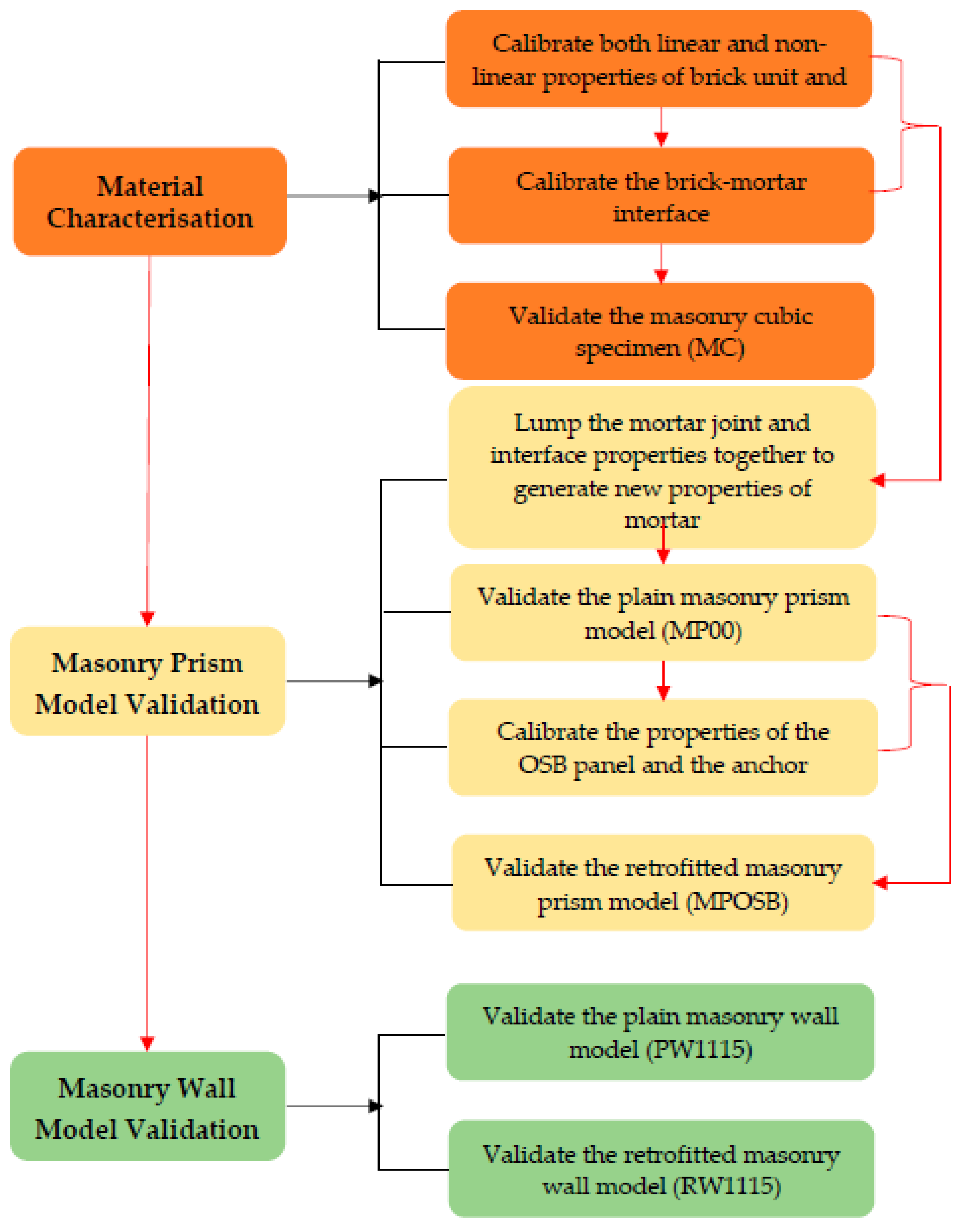
Numerical modelling and analysis were developed in ABAQUS/CAE [26]. As formulated for the experimental work, the numerical analysis was also articulated in three stages (Figure 2).
The first stage is the numerical simulation of the compression test on the masonry cubic specimens presented as part of the material characterisation test. The purpose of this stage was to obtain accurate mechanical properties of the unit, mortar and the interfacial properties of the unit-mortar joint that is necessary to produce detailed micromodelling of masonry structures. To achieve this, a complete description of each component was done based on the experimental results of compression tests on brick units, mortar and the masonry cubic assemblage.
Second, numerical simulations of the flexural bond strength tests on small-scale masonry prisms were developed to capture the damage and failure pattern of the masonry prisms (MP) tested. This stage was articulated in two steps, which included (i) validation of the plain MP using the already calibrated properties of the brick units and new properties of mortar and the interface together, and (ii) validation of the retrofitted MP, where the properties of the retrofit materials, which are the OSB panels and the connections, were calibrated and the components were added to the already validated plain MP model to generate the retrofitted model.
In the third stage, the numerical simulations of the out-of-plane loading tests on the large-scale masonry walls were carried out. In addition, for this case the plain wall model was first validated and then the retrofitted wall was modelled with the addition of OSB panel and connections. At each stage of the simulation, the models developed were validated using the test results.
3. Experimental Study
Although this paper focuses on the numerical study, still, sufficient information about the experimental studies are provided in this section, with special focus on the applied testing methodology and the primary findings. The reader is referred to previous works [15,18,19] for the details of experimental works on the material characterisation, small-scale and large-scale tests, respectively.
3.1. Material Characterisation
3.1.1. Experimental Test on Brick Unit, Mortar and Masonry Cubic Specimens
For the material characterisation tests (Figure 3), an experimental program was developed based on the components (brick unit and mortar) and assemblage (brick masonry cubic specimen), as shown in stage 1 of Table 2.
Each test on the component was carried out according to the relevant British standards, and allowed for the definition of the dimension, dry density, water absorption, compressive strength, modulus of elasticity and Poisson’s ratio of the brick units.
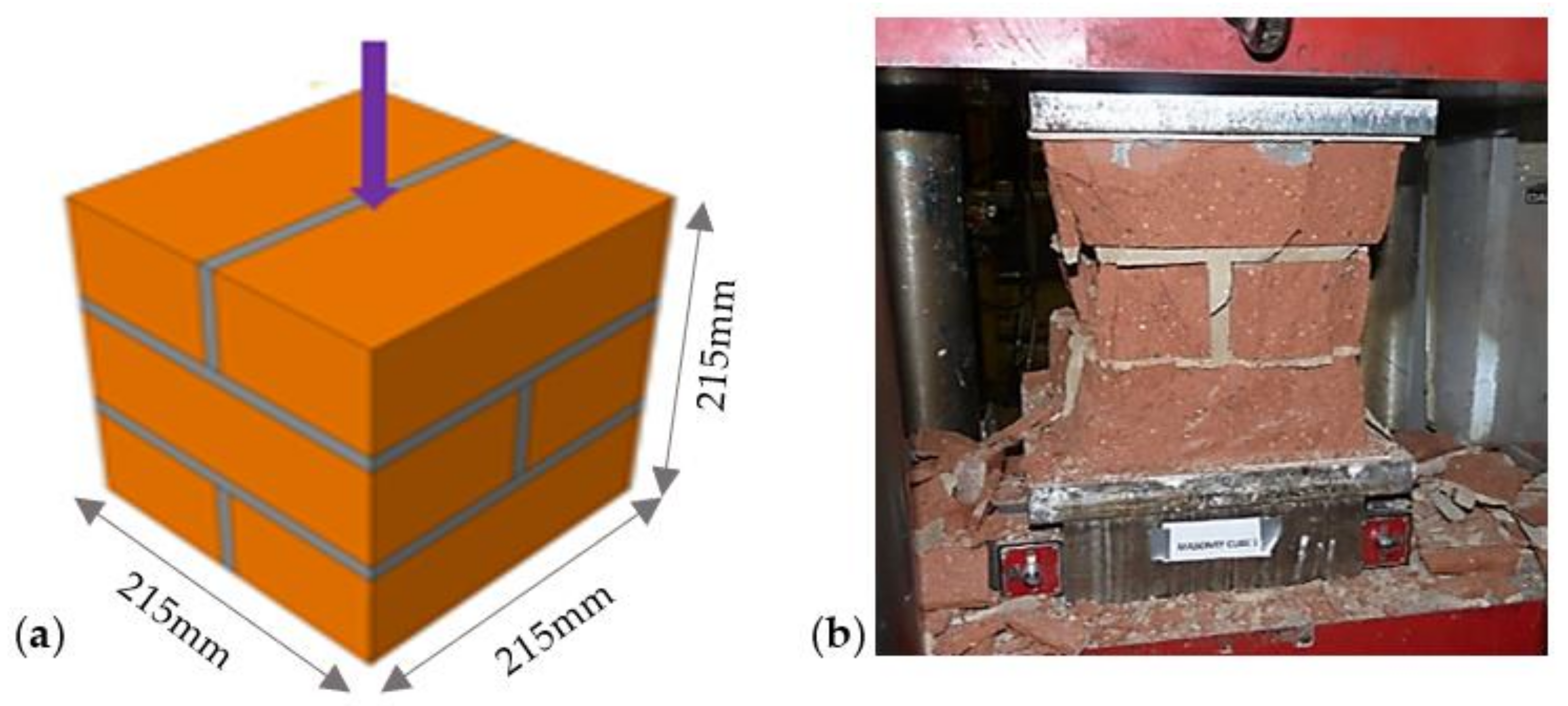
After testing the brick unit and mortar independently, six masonry cubic (MC) specimens of 215 × 215 × 215 mm were tested to understand how the selected brick units and the adopted mortar mix ratio work together. The MC specimens were constructed using English bond consisting of alternate rows of headers and stretchers, which is the oldest form of brick bond popular until the late 17th century [27]. After the construction, each sample was wrapped with polythene sheet for 14 days and thereafter opened and cured further for 14 days in the laboratory to allow the samples to achieve its standard strength. An attempt to measure the deformation of the MC was made by attaching four LVDTs to the MC before testing (Figure 3c). The specimens were carefully aligned with the centre of the ball-seated platen, under the compression testing machine, with 2 mm-thick plywood placed on the top and the bottom of the MC. A uniformly distributed load was applied gradually in equal increments continuously at 4 kN/s rate up to failure.
3.1.2. Summary of Characterisation Test Results
Generally, the properties of the brick units obtained from the test indicate that the selected bricks were of good quality, conform to the declared specifications from the manufacturer (Table 2) and acceptable for the proposed experiment. Hence, all the bricks used in this study were sourced from the same manufacturer (Wienerberger Ltd., UK).
For the masonry cubic specimen, the average compressive strength obtained from the experiments was 46.4 N/mm2. Most importantly, the observation shows that the failure modes of both the brick units and MC are brittle. The failures of MC specimens were characterized by vertical splitting cracks appeared first in the central unit and extended to the other units as the stress increased (Figure 4). This failure pattern is due to the presence of the vertical joints and the lateral expansion of the mortar inducing high tensile strength in the bricks.
3.2. Small-Scale Tests
3.2.1. Flexural Bond Strength of Masonry Prisms
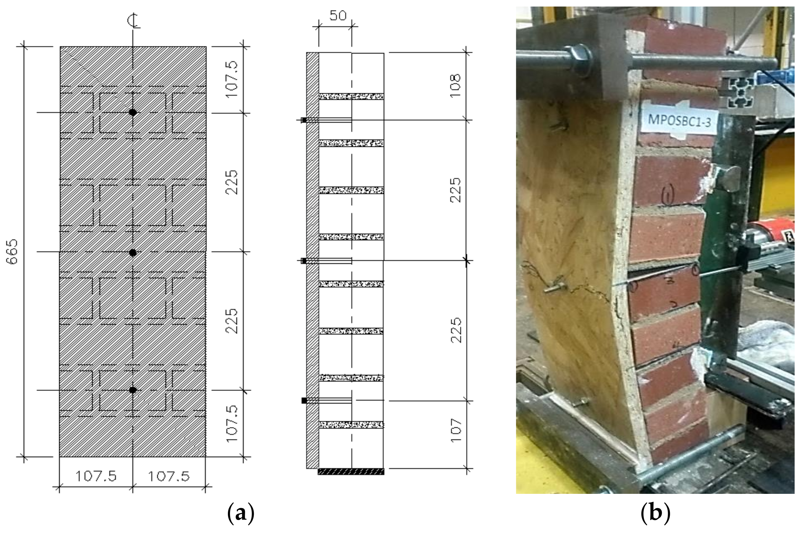
Flexural strength of masonry prisms (MP) was obtained from a four-point bending test conducted on MPs according to the provisions of [16,17]. The small-scale test helped to understand the behaviour of masonry and the connection between the masonry prism and timber panel proposed for retrofitting masonry wall. The test provided an insight on the effectiveness of the proposed timber panel retrofit on flexural behaviour of masonry prisms, and it also enabled the design and implementation of the large-scale test to be straightforward. The MP test specimens were constructed as nine courses stacked bonded prisms, 215 × 102.5 × 665 mm with mortar joints of 10 ± 1.5 mm thickness. The test specimens were constructed using English bond consisting of alternate rows of headers and stretchers. Nine single leaf masonry prisms (MPs) were tested in the laboratory under the four-point bending test using a quasi-static monotonic loading scheme. The small-scale experimental campaign involved testing (a) three samples of plain MP to serve as references to measure the effectiveness of the proposed retrofit techniques; (b) three samples of retrofitted MP, each retrofitted with an 18 mm-thick OSB type-3 timber panel using adhesive anchor connections (C1); and (c) three samples of MP retrofitted with 18 mm-thick OSB type-3 using mechanical connections (C2).
The MP specimens constructed on the 10 mm-thick steel plate were tested adopting the test set up shown in Figure 5. No vertical precompression loads were applied to any of the nine specimens. The specimen on the steel plate was rested on a 25 mm-diameter cylindrical roller with the axis of the roller parallel to the face of the specimen to allow it to freely rotate around its base while deflecting out-of-plane and prevent a restrained end condition. At the back of the specimen, a 25 × 5 mm-thick metal plate was fixed across the middle of the top and bottom brick unit each. This 5 mm-thick plate provided a smooth contact for the Ø25 mm supporting rollers fixed on an existing steel reaction frame in the laboratory. On the front side of the specimen, two additional 25 × 5 mm-thick metal plates were fixed at the third and seventh course of the specimen each to provide a contact for the loading rollers.
The loading of the specimens is such of a four-point testing arrangement, where the loads were applied on the specimen using a high-force hydraulic jack and distributed through a spreader beam. The spreader beam spanned between two Ø25 mm cylindrical rollers placed across the third and seventh course of the specimen. The direction of the load application is perpendicular to the specimen surface. The applied load on the masonry prism was monitored using a 200 kN-capacity ring load cell. Simultaneously, four linear variable displacement transducers (LVDTs) were used to record the deflections of the specimen along the centre, mid-top and bottom of the specimen.
The test was load controlled, and the loading scheme was such that an initial load of 200 N increments at every two minutes up to the occurrence of first cracks was applied. This loading rate represents 1/10th of the expected maximum load. The load increment was chosen so that a sufficient number of readings were obtained to determine definitely the load–deformation curve [16]. After the first crack appeared, the loading was increased continually at a rate of 2 N/s, up to the cracking/failure of MP specimens.
3.2.2. Summary of Small-Scale Test Results
The experimental results were first expressed in terms of the load–displacement curve, which represents the relationship between the applied out-of-plane loads and the net out-of-plane displacement in the mid-height of the test specimens (Figure 6). Thereafter, the observed failure pattern of the MP specimens tested is presented in Figure 7 and Figure 8. The maximum load, corresponding displacement at failure, flexural strength and the toughness of the tested specimens were all determined and are presented in Table 3. The flexural strength was calculated from the bending theory using the maximum failure load. The toughness (i.e., energy absorbed) of the specimens is estimated from the load–displacement curve (Figure 6) using the method based on ASTM 1609. This toughness is estimated as the overall (i.e., the total area under the load–displacement curve) and the limiting toughness. The limiting toughness is the area under the curve up to a limited displacement of span/250 [29]. This is done to understand the toughness gained by the specimens when undergoing an acceptable displacement without adverse effect. Thus, the limiting toughness actually estimates the improvement due to the retrofit application in an acceptable range.
In Table 3, the average value of each property for each group of the specimen (i.e., MP00, MPOSBC1 and MPOSBC2) was evaluated and compared. The comparison shows that the maximum load that can be attained in MP when retrofitted with an OSB panel is 7.4 times and 5 times larger than that of plain MP for connection type C1 and C2, respectively. This means that the retrofitted MPs were able to take more loads by displacing more without sudden failure, which led to increased out-of-plane displacement, which is 2.1 times and 1.7 times that of plain MP, for samples retrofitted with C1 and C2, respectively. Similarly, the increment in the flexural strength is also significant when MP is retrofitted with OSB panel. C1 offered the largest increment in terms of load capacity and flexural strength.
Further analysis of the data in Table 3 reveals that the toughness gained due to the retrofit application when taken up to the failure of the OSB is enormous. An improvement of 11 times and 7 times that of plain MP was recorded for connection type 1 and 2, respectively. However, having established the need for consideration of performance at the limiting displacement, the analysis shows that the application improved the toughness by 1.7 times that of the plain wall for C1 and a little increment of 1.1 times the plain wall for C2. The increment in the load capacity of the retrofitted specimens at this limiting displacement is about 3 times and 2 times that of the plain wall for C1 and C2, respectively. Still, C1 offers the largest improvement in terms of gained toughness at both the limiting displacement and overall failure.
3.3. Large-Scale Tests
3.3.1. Out-Of-Plane Bending Test on Masonry Walls
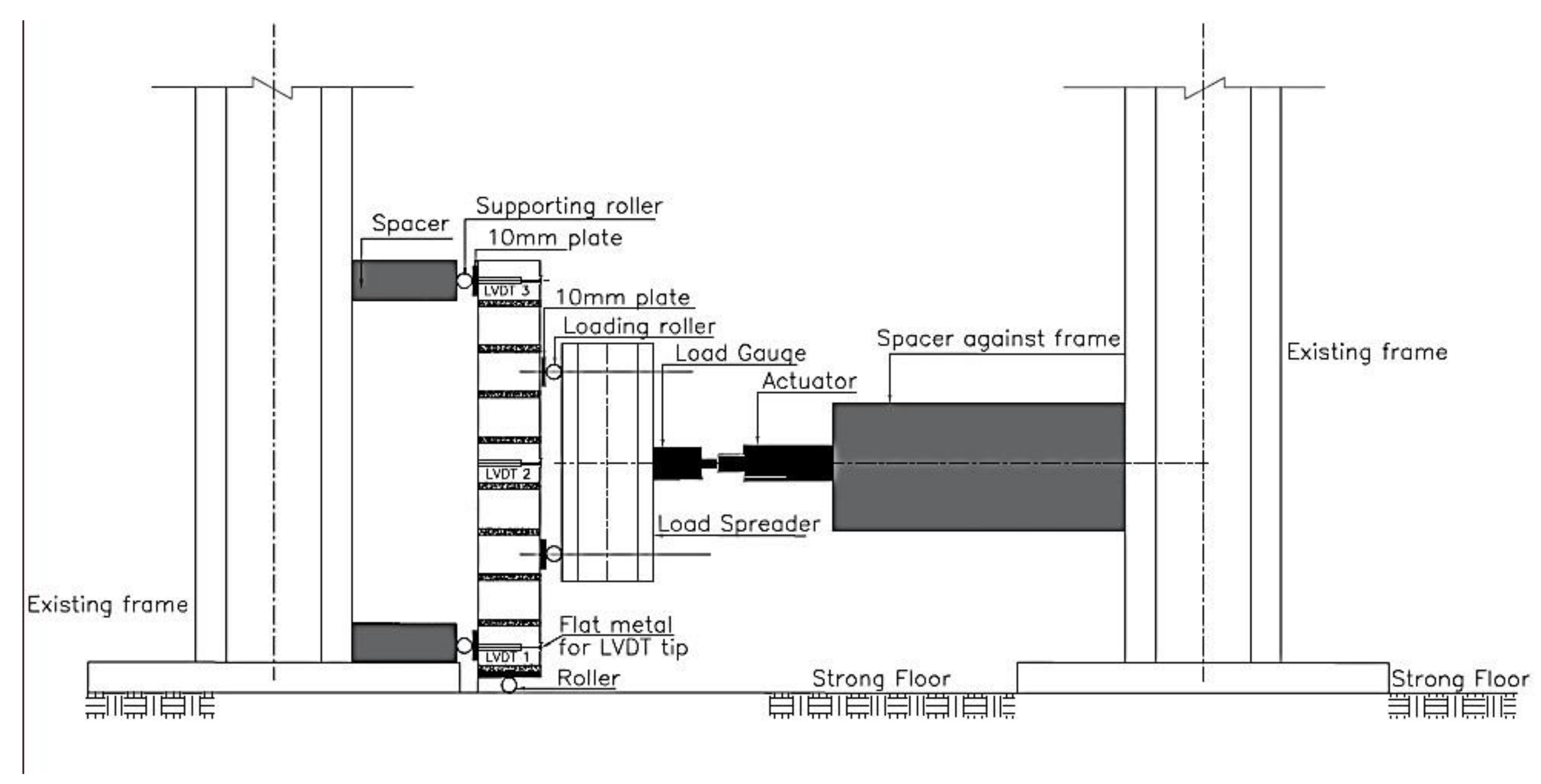
The test setup for the large-scale test is similar to that of the small-scale test. Here, 1115 × 1115 × 215 mm masonry wall specimens were tested under a four-point loading test arrangement (Figure 9) to assess their flexural behaviour. The test was load controlled and the load was applied to each tested specimen using a hydraulic ram and was distributed through a steel spreader arrangement in the central area of the wall. All specimens were tested with a simple supported boundary condition and a vertical precompression load (305 × 305 × 240 UC section amounting to a 3 kN load) on top of the wall. The specimen constructed on reinforced concrete footing was rested on a 50 mm diameter cylindrical roller with the axis of the roller parallel to the face of the specimen. At the back of the wall, a 5 mm-thick metal plate was fixed across the middle of the top and bottom course of the wall to provide contact for the simple support. Similarly, a 5 mm-thick metal plate was fixed at 1/4th and 3/4th of the specimen height at the front side to provide contact on which the loading roller rests (Figure 9).
The loading scheme was such that an initial load was applied continuously at a rate of 1 kN/min for up to 5 kN and then maintained for a 5 min period. The load steps were repeated continuously for a 10, 15, 20, 25 and 30 kN load and maintained for a 5 min period at each load step. After that, the load was increased continuously to the failure of the specimens. In order to obtain the maximum capacity of the retrofitted walls, the applied load was increased continually after the first crack until additional cracks were formed in the retrofitted specimens and ultimately the timber at the back of the masonry walls was broken. During testing, the applied load on the wall was monitored using a 200 KN-capacity ring load cell. In addition, eight LVDTs were used to record the deflections of the specimen along the wall center, mid top and bottom.
3.3.2. Summary of Large-Scale Test Results
Figure 10 shows the load–displacement curves obtained from the experiment. The average maximum load attained by the plain wall (PW1115) is 39,025 N and was chosen as a baseline to evaluate the effectiveness of the proposed timber-retrofit technique in both single-sided (1SRW1115) and double-sided (2SRW1115) retrofitted walls. The average maximum load and out-of-plane displacement at the specimen’s mid height for 1SRW1115 and 2SRW1115 were estimated as (114,622 N, 25.88 mm) and (120,559 N, 12.61 mm), respectively. In addition, the summary of the main results of the out-of-plane bending test is presented in Table 4 for the first/initial cracking and failure load, and their corresponding displacement, limiting and overall toughness.
The comparison in terms of capacity at first crack (Table 4) shows that the load that caused the first crack in 1SRW was 1.4 times the maximum load at the failure of PW. In addition, the first crack on the 2SRW specimen occurred at a load that was 1.8 times the failure load of PW. This shows that the 2SRW resists more load before the first crack, about 1.4 times that of 1SRW. At the failure point, the maximum load capacity of masonry wall retrofitted with OSB panel was 2.9 times and 3.1 times that of PW for 1SRW and 2SRW, respectively (Table 4). Unlike the load at the first crack, the load capacity of 2SRW was only 1.04 times that of 1SRW.
The analysis of results shows a significant increase in the out-of-plane displacement of retrofitted walls. This is due to the application of the OSB timber panel that offered the masonry wall a significant lateral resistance once the mortar interfaced cracked. As such, the retrofitted specimens were able to take more loads and absorbed more energy by displacing more without sudden failure. The increment in the out-of-plane displacement of the retrofitted walls was 6 times and 3.0 times that of PW for 1SRW and 2SRW, respectively.
Similar to the observation in the small-scale test, the overall toughness gained due to the retrofit application when taken up to the failure of the OSB is such that an improvement of 16 times and 10 times that of the plain wall was estimated for application on single and both sides, respectively. However, the performance of the proposed technique at the limiting displacement was quite different with the double-sided showing more toughness gained than the one-sided application (2.4 × PW and 1.6 × PW for double and single-sided, respectively). The analysis shows that the double-sided application offers the most improvement in the toughness at the limiting displacement. Thus, the double-sided is the best option when higher energy absorption is required in a real situation.
In terms of observed failure pattern (Figure 11), it emerged that the failure of the PW was sudden with the evolution of a crack opening in the mortar bed joint almost at the specimens’ mid-height. The failure (cracking) abruptly occurred between the interface of the mortar joint and brick unit, which then cut across the whole specimen thickness. Whereas the application of the OSB type-3 to retrofit the walls shows that the walls were able to take more loads after the first crack, which subsequently led to the formation of other horizontal cracks in the bed joint within the middle third of the walls. The failure/collapse of the retrofitted specimens occurred when the applied OSB timber reached its ultimate strain and broke. The application ensured that sudden failure was avoided.
4. Numerical Study
This section presents the numerical simulations of the three stages experimental work briefly discussed in Section 3 (i) numerical simulation of the compression tests on the masonry cubic specimens, (ii) numerical simulation of the flexural bond strength tests on small-scale masonry prisms and (iii) numerical simulations of the out-of-plane loading tests on the large-scale masonry walls. At each stage of the simulation, the models developed were validated using the experimental data.
4.1. Numerical Simulation of Compression Test on a Masonry Cubic (MC) Specimen
4.1.1. Description of the Masonry Cubic Model
The compression test on MC specimens described in Section 3.1 was simulated by FE analysis using the ABAQUS software [29] to obtain the full mechanical properties of the unit, mortar and the interfacial properties of the unit-mortar joint that is necessary to produce a detailed numerical analysis of the masonry wall. The MC numerical model was calibrated through the following four steps:
- Material elastic properties for the unit and mortar joint were estimated based on the results of the compression tests on the individual components.
- The brick–mortar interfaces were calibrated with the ABAQUS default penalty stiffness enforced while adjusting the coefficient of friction based on the comparison of the numerical results with those obtained in the experiments.
- Lastly, the influence of the mesh density, i.e., the approximate global size of mesh, was studied.
The numerical model of a masonry cube (MC) was created using a three-dimensional solid (or continuum) element in ABAQUS. In particular, hexahedral 8-node linear brick, reduced integration and hourglass control (C3D8R) were selected to generate the mesh that represents the brick and mortar joint. The unit and joint (bed and perpend) were defined using their respective elastic properties obtained experimentally. The nonlinear behaviour of the brick unit and mortar, both in a compression and tension regime, were accounted for in the FE model using the CDP constitutive model. The brick–mortar bond failure behaviours were also considered by using the nonlinear cohesive interfaces. ABAQUS contact penalty approach was enforced for the interaction between the brick and mortar interface. This means that the contact between the mortar interface and the unit interface is enforced by contact constraints in the normal direction. Simulia [26] iterated that the penalty method typically does not generate additional degrees of freedom, unlike the contact constraint options, which would always generate Lagrange multiplier degrees of freedom. In tangential, the frictional behaviour between the unit–mortar interface was calibrated using a coefficient of friction (µ) of 0.75.
For the boundary condition, the nodes at the top of the cubes were restrained in the x- and z-direction while the bottom nodes were restrained in all the three directions (x, y, z) to replicate the friction in the test condition of the specimen. Figure 12 shows the general assemblage of the masonry cubic model, FE mesh and the boundary condition.
4.1.2. Summary of Results Obtained from Masonry Cubic Model Analysis
The principal stress obtained from the numerical analysis is compared to the average compressive strength of the specimens obtained experimentally. The maximum stress obtained from the numerical model is 48.7 N/mm2. This value is only 5% different from the average compressive strength of masonry obtained from the experiment (46.4 N/mm2). Figure 13 shows the stress contour plots obtained numerically for the MC model compared with the observed failure pattern from the test. Significantly, the failure mode observed in the model output (Figure 13a) is similar to what was observed experimentally (Figure 13b) with the maximum compressive stress occurring at the bottom edges of the model. The cut along the y-plane of the model revealed the tensile stress distribution in the model. The regions showing the highest values (colours tending towards red at edges of the model) can be associated with the maximum stress, which is an indication of where cracks are expected to appear. This shows that higher concentration of the stress is consistent with the portion that split off in the experiment. Therefore, Figure 13b can be likened to the inner region of the stress diagram obtained from the numerical simulation.
The FEs model developed for the masonry cube was able to predict the behaviour and failure of masonry cube with a difference of 5% between numerical value and experimental value. This indicates that the calibrated mechanical properties of the brick unit and mortar joint represent the properties of brick and mortar used in the experiment. Therefore, Table 5 presents the already calibrated properties of the unit and joint for the small- and large-scale simulations used subsequently in Section 4.2 and Section 4.3.
4.2. Numerical Simulation of Small-Scale Test on a Masonry Prism (MP) Specimen
4.2.1. Development of the Masonry Prism Model
The tested plain and retrofitted masonry prisms were modelled in FE to analyse further the efficiency of the proposed timber masonry retrofit technique. The model adopted was based on the micromodel technique developed in ABAQUS. The model was created with all the components in the four-point loading test properly modelled to obtain the best accurate results from the FE analysis.
Table 5 summarises the material properties of all components, including those for the anchor connectors and OSB timber panels that were included for the retrofitted models.
Two different models were created for the plain and retrofitted MP, and the models were labelled as MP00-NM and MPOSB-NM, respectively. MP00-NM comprised three components; brick unit, mortar and steel plate for load and support application. The brick unit (215 × 102.5 × 65 mm) and mortar joint (10 mm thick) were modelled as 3D deformable parts and meshed with a hexahedral 8-node linear brick, reduced integration and hourglass control (C3D8R) which has an improved convergence. The steel plate for load and support application (5 mm thick) was modelled using a 3D discrete rigid element and discretised by rigid element R3D4 to represent a part that is much stiffer (deformation negligible) than the masonry prism. For MPOSB-NM, two additional parts, an 18 mm-thick OSB timber panel and anchor rod, were modelled as 3D deformable parts and meshed with a hexahedral 8-node linear brick (C3D8R). The OSB timber panel and brick units were drilled at the connection locations, as done in the experiment to apply the retrofit to the MP.
The process to build the full model requires that an appropriate interaction and constraints between model components be implemented to represent the relationship between each element in the model. In the micromodelling strategy employed, the brick–mortar bond interface was not specified separately, so the brick continuum and mortar continuum were merged to assume a perfect bond, as shown in Figure 14a. In order to place the loading at the front face of the model, the surface of the steel plate was tied to the surface of the brick at the third and seventh course using tie constraints (Figure 14b). Similarly, the steel plates were tied to the top and bottom brick or OSB timber at the back of the MP model for the retrofitted MP, as shown in Figure 14c, for the support application. The use of tie constraints ensured that the steel plate could not slip from the brick unit or the OSB timber panel during the analysis.
In addition, frictional, normal hard contact was specified between the surface of the OSB timber and MP model, as shown in Figure 14. For this analysis, the friction coefficient was taken as 0.5, which is a typical coefficient of friction between timber and brick.
For the anchor connection, the nodes on the surface of the brick around the connection holes were connected to the surface of the anchors (surface-to-surface contact) using the default contact enforcement in ABAQUS (Figure 14). This connection ensures that there was a full adhesive bond between the anchor and the surface of the holes in MP. This kind of connection represents the retrofit system where the OSB timber panel is connected to the MP using an adhesive anchor identified as the best performing connection type in the experimental study.
Moreover, proper consideration of the applied boundary conditions in the numerical simulation was taken. The models (MP00-NM and MPOSB-NM) were constrained to replicate what was done experimentally to enable a sound basis for comparison of results. In the developed models, the nodes at the middle of the back-steel plate at the top of the MP were restrained in the x- and z-direction. In addition, the plate at the bottom was restrained in all the three directions (x, y, z) at the middle nodes to replicate the support condition of the tested specimen (Figure 14d).
The loads considered in this analysis are self-weight of the model and applied unit load in the out-of-plane direction at the third and seventh course of the model. This loading and support arrangement is a replica of the four-point bending test carried out in the laboratory. The out-of-plane load is applied as a unit uniform distributed load (UDL) on the steel plate tied to the front face of the model (Figure 14d). The analysis is the static RIKS load control method, similar to the test condition. The total load capacity of the model is measured as the load proportionality factor multiplied by the applied load in Newton (N).
4.2.2. Summary of Results Obtained from the Small-Scale (MP) Numerical Analysis
Figure 15 presents the failure of the model alongside the actual damaged specimen obtained from the test for MP00. The comparison shows that the failure of MP00-NM occurred in the bed joints within the loading span of the specimen. In the actual test, the total failure occurred in one bed joint, but the numerical model shows the failure in two symmetrical bed joints. This is because the numerical model created had the same property for all joints, which was not possible in the test due to variation during specimen construction. Hence, the symmetrical joints in the model experienced the same load, and thus the failure was simultaneous, whereas the failure occurred in the weakest joint during the experimental test.
For MPOSB-NM, the damage pattern compared with the experimental observation is shown in Figure 16. In the model, the global damage pattern shows all the areas where the failure occurred in all the three tested specimens. References were made to two specimens highlighted for simplification (Figure 16). The numerical damage compared with the experimental one proves that the calibration was performed successfully for the plain and retrofitted model since the damage pattern corresponds to one found in all three tested specimens.
In terms of the load–displacement comparison, Figure 17 shows that the numerical outputs compared well with the graph showing that the numerical model captures the experimental envelope. The model predicted the toughness, peak load and the corresponding failure to within less than 5% of the average results obtained from the test (Table 6). Hence, the simulation process including the input parameter, loading conditions, applied constraints and interaction between parts were fit to extend the numerical study to the large-scale masonry wall, as presented in Section 4.3.
4.3. Numerical Simulation of Large-Scale Test on a Masonry Wall Specimen
4.3.1. Development of the Masonry Wall Model
In this section, the finite element analysis to simulate the large-scale test on the masonry wall is presented. Similar to the numerical simulation of the small-scale test performed in Section 4.2, the model was created with all the components in the experimental setup included. Three different models were created, each for the plain wall (PW1115-NM), one side retrofitted masonry wall (1SRW1115-NM) and two sides retrofitted masonry wall (2SRW1115-NM). The model creation follows the same process with the brick unit and mortar joint modelled as 3D deformable parts and meshed with a hexahedral 8-node linear brick (C3D8R). The steel plate for load and support application was also modelled using 3D discrete rigid elements (R3D4). The interaction between components and boundary condition is the same as in the MP model (Figure 14).
Figure 18 shows the model, boundary condition and loads applied on large-scale models using the 2SRW1115-NM as an example. Due to the symmetry of the wall specimen, only half of the arrangement was modelled. Thus, another boundary condition (i.e., ZSYMM (U3 = UR1 = UR2 = 0)) was placed in the z-axis to replicate the symmetry in the specimen. The analysis was load control, similar to the test condition, and the total load capacity of the model was measured as the load proportionality factor multiplied by the applied load.
4.3.2. Summary of Results Obtained from Large-Scale Masonry Wall Numerical Analysis
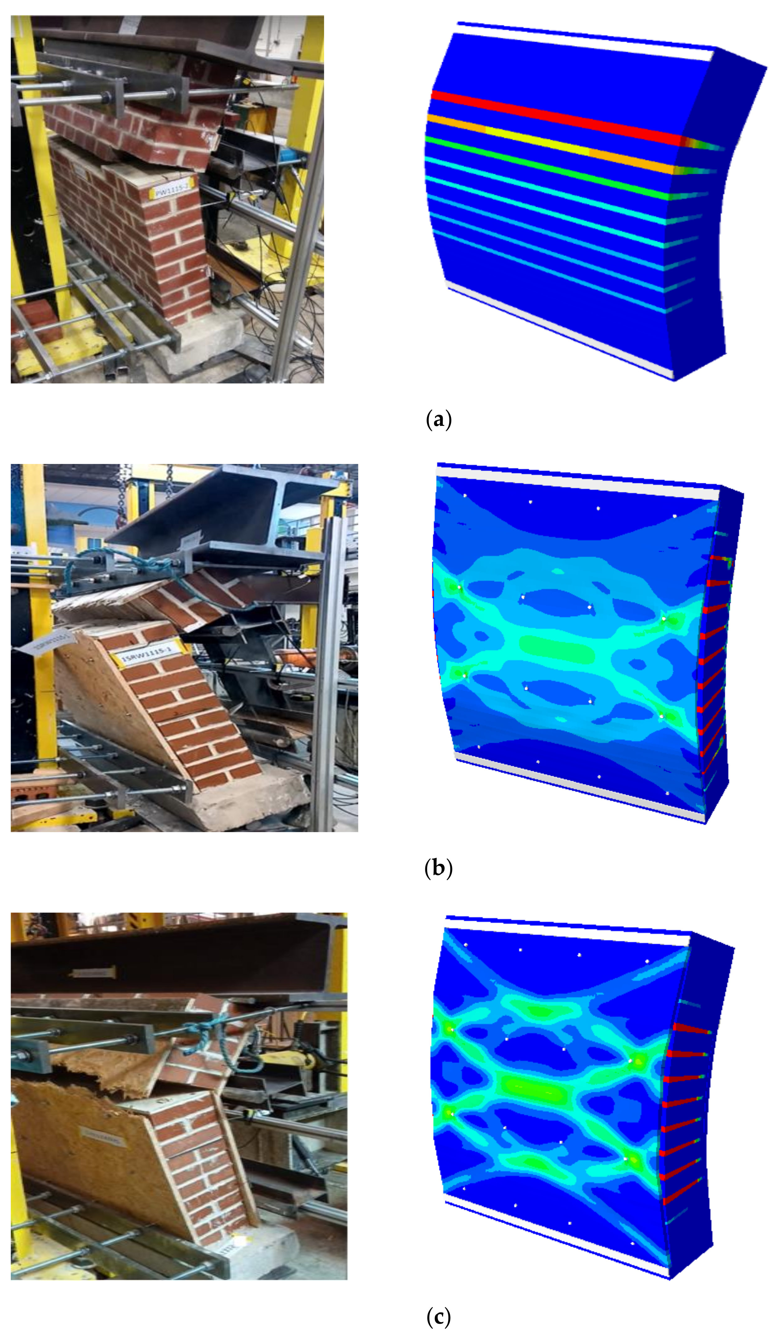
The results obtained from the numerical simulation of the large-scale walls were compared with the test results in terms of both the capacity and failure mode. The comparison shows a relatively good agreement between the numerical and experimental results. Figure 19 shows the failure of the model alongside the actual damaged specimens obtained from the test. For the plain wall (PW1115), the comparison (see Figure 19a) indicates that the specimen failure occurred in similar bed joints, which is in the ninth and tenth row of the experimental specimen. Correspondingly, the tension damage in the model is largest in the tenth row. The failure in the test specimen crossed the perpendicular joint due to the weaker zone in the perpend joint. This weakness was not observed in the numerical model because the property of the mortar joint is the same for the bed joint and perpend joint. Indeed, the bed joint is the one in maximum tension during loading. The experimental failure was only due to variance in the specimen joint during construction, which makes the perpend joint in that zone weaker than the bed joint.
Moreover, the numerical failure of the one side retrofitted model (1SRW1115) was compared alongside the damaged specimen from the test (Figure 19b). The damage pattern shows that the OSB panel at the back of the specimen failed after the mortar joint failed. The location at which the OSB failed in the model is similar to what was observed in the test with the failure point being within two rows of connections.
Similar to the previous two models, the observed failure pattern for both the numerical and experimental specimens was compared for the two-sided retrofitted specimens, as shown in Figure 19c. The failure pattern of the model developed for 2SRW1115 is also in good agreement with the experimental failure. The damage pattern indicates that the OSB panel in the tension side (at the back of the specimen) failed after the mortar joint failed. The location at which the OSB failed in the model is similar to what was observed in the test with the tensile stresses spreading across the middle of the panel. The OSB in the compression face did not fail, as also seen in the experiment. The damage shown on the OSB on the compression side (i.e., loading face) only occurred after the failure and, as such, not replicated in the model.
Additionally, the load–displacement curve obtained from both the numerical analysis and experimental test is presented in Figure 20. The toughness, maximum load and corresponding displacement at the failure of the model are within less than 10% of the average results obtained from the test (Table 7). Figure 20a shows that there is a little variance in the displacement for applied load higher than 24,000 N; this variation is due to the movement of the wall during testing at the initiation of the crack. This behaviour was noticed during the experiment ([6]); and it is primarily due to instability of the specimen caused by the test arrangement (as also indicated in [34,35]). However, since the numerical model assumed a perfect arrangement, the response is not captured and will be ignored.
Similarly, the load–displacement curves for 1SRW are compared in Figure 20b. The maximum load and the corresponding displacement of the numerical model compared well with the experimental results. The difference in the peak load is within less than 2% of the average test results, as shown in Table 7. However, the difference in the out-of-plane displacement from the test and model is about 8.3%, which is still less than 10% and therefore acceptable. The variation in the displacement of the numerical model from the test behaviour is obvious from the load–displacement curve in Figure 20b. Again, this behaviour is attributed to the difficulty in the stability of the specimen during the experiment when the walls begin to damage. This can be ascertained from the fact that the curves compared well up to around 50,000 N load, which is when the specimen failure started.
In addition, the load–displacement curve for both the experimental and numerical model for 2SRW is presented in Figure 20c. Again, the difference between the numerical curve and experimental curve, especially at the dilatant parts of the curve after 65,000 N and subsequent steps, represent the jump in the displacement of the specimen. This jump is attributed to the stability issue in the specimen, which happened after the joint bed failed during testing. The inference from the load–displacement curves means that the model developed agrees with the experimental results. The difference in the maximum load and corresponding displacement of the numerical model and the experimental results is also within less than 10% of the average test results shown in Table 7.
5. Conclusions
In this paper, a three-stage numerical study, calibrated and validated through experimental data obtained from a three-phase experimental campaign conducted by the authors, is presented. This paper aims to numerically evaluate the capacity and effectiveness of a proposed timber-based retrofit technique against out-of-plane failure. After an introduction of the overall conceptualisation of the study and brief detail of the conducted experimental program, this paper focuses on the development and analysis of a 3D finite element computational model using ABAQUS FEA software.
The first stage of the numerical analysis was the material characterisation, where a detailed micromodelling approach was employed to simulate the compression test on the masonry cubic (MC) specimen. The linear mechanical properties of the brick unit and mortar obtained directly from the compression test on the brick unit and mortar were used as the input parameter. For the nonlinear mechanical properties of the unit and mortar, the concrete damage plasticity (CDP) model available in ABAQUS was used to describe the constitutive material relations. To do this, the ductility index and fracture energy data available in many literature reports [27,30,31,32,33] were used. Thereafter, the brick–mortar interface was calibrated against the experimental data. The FE model developed was able to predict the behaviour and failure of the MC specimen with a difference of 5% between the numerical value and experimental value. Hence, the main finding from this phase was that the calibrated material properties for the unit and mortar joint used in the numerical simulation of the MC compression tests represented the approximate properties of the materials. After that, the properties were later used to analyse the out-of-plane response of small-scale and large-scale plain and retrofitted masonry wall in the subsequent phases.
The numerical simulation of the four-point bending test for both the small-scale and large-scale test were also carried out to simulate the capacity and failure pattern of the masonry prism and wall tested in the laboratory. As highlighted in Section 4.2, the model strategy adopted for both masonry prism and wall was based on the detailed micromodel technique with the brick mortar interface precluded to avoid ABAQUS convergence issue because of too many contacts between the unit and mortar. Thus, the interface properties were lumped into the properties of the mortar, and new nonlinear properties of mortar were obtained and calibrated using the test results of the small-scale plain masonry prism. The properties of the brick units calibrated in the previous step were used. In addition, the damage constitutive model available in ABAQUS was used to define the nonlinear behaviour of OSB timber and incorporated together with pure elastic properties of the anchor connection for the creation of the retrofitted model.
The analysis of the masonry prism/wall model under a continuous increase of load in the form of a load–displacement curve was obtained using the static RIKS method (arc-length control). The comparative analysis of the numerical results with the test results confirms that the FE models developed adequately captured the behaviour of both the plain and retrofitted model to the ultimate load. The models also show an excellent correlation of the compressive damage (DAMAGEC) and tensile damage (DAMAGET) with the experimental failure pattern. Generally, the model predicted the peak load and the corresponding failure, toughness and resilience to within less than 10% of the average test results.
Numerically, this study contributed to the modelling of masonry walls retrofitted with OSB panels considering the mechanical properties of individual components, i.e., masonry unit, mortar and the retrofit materials (OSB timber and anchor connectors). Its application to simulate the behaviour of the retrofit system will facilitate laboratory experiments in studying further the efficiency of the proposed retrofit techniques. As such, an extension of these numerical studies is being carried out and will be presented in a separate article to assess the model capability to simulate URM walls retrofitted with different OSB panel thickness, different spacings between connections and different positions for the retrofit application [33]. Further study on the influence of other parameters, such as different wall boundary conditions, different loading scenarios, size and location of openings, and different masonry types (strong joint and weak unit type), on the proposed retrofit techniques are also suggested for future investigation.
Author Contributions
Methodology, O.I. and J.A.D.; software and formal analysis, J.A.D.; writing—original draft preparation, J.A.D.; writing—review and editing, O.I.; funding acquisition, O.I. All authors have read and agreed to the published version of the manuscript.
Funding
This research was funded by EPSRC (EP/V011820/1) and University of Leeds, LARS scholarship.
Data Availability Statement
The data presented in this study are available on request from the authors: [email protected]; [email protected].
Acknowledgments
The authors acknowledge the EPSRC (EP/V011820/1) for funding this study, and Paulo Lourenco and Luis C. Silva for the critical discussions in the development of the numerical model.
Conflicts of Interest
The authors declare no conflict of interest. The funders had no role in the design of the study; in the collection, analyses, or interpretation of data; in the writing of the manuscript, or in the decision to publish the results.
References
- Iuorio, O. Energy retrofit of tower blocks in UK: Making the case for an integrated approach. Tech. J. Technol. Arch. Environ. 2018, 1, 45–48. [Google Scholar]
- Wang, C.; Sarhosis, V.; Nikitas, N. Strengthening/retrofitting techniques on unreinforced masonry structure/element subjected to seismic loads: A literature review. Open Constr. Build. Technol. J. 2018, 12, 251–268. [Google Scholar] [CrossRef] [Green Version]
- Menon, A.; Magenes, G. Definition of seismic input for out-of-plane response of masonry walls: I. parametric study. J. Earthq. Eng. 2011, 15, 165–194. [Google Scholar] [CrossRef]
- Binda, L.; Cardani, G. Seismic vulnerability of historic centers: A methodology to study the vulnerability assessment of masonry building typologies in seismic area. In Handbook of Research on Seismic Assessment and Rehabilitation of Historic Structures; IGI Global: Hershey, PA, USA, 2015; pp. 1–29. [Google Scholar] [CrossRef]
- Donmez, C.; Erberik, M.A. A case study for seismic assessment and restoration of historic buildings: The arditi residence. In Handbook of Research on Seismic Assessment and Rehabilitation of Historic Structures; IGI Global: Hershey, PA, USA, 2015; pp. 381–400. [Google Scholar] [CrossRef]
- Dauda, J.A. Numerical and Experimental Investigation of Unreinforced Masonry Wall Retrofitted with Timber Panels. Ph.D. Thesis, University of Leeds, Leeds, UK, 2020. [Google Scholar]
- Glass, S.V.; Zelinka, S.L. Moisture relations and physical properties of wood. In Wood Handbook: Wood as an Engineering Material; Risbrudt, C.D., Ritter, M.A., Wegner, T.H., Eds.; United States Department of Agriculture Forest Service: Madison, WI, USA, 2010; pp. 4–17. [Google Scholar] [CrossRef] [Green Version]
- Pelenur, M. Retrofitting the Domestic Built Environment: Investigating Household Perspectives Towards Energy Efficiency Technologies and Behaviour. Ph.D. Thesis, University of Cambridge, Cambridge, UK, 2013; pp. 1–332. [Google Scholar]
- Sustersic, B.; Dujic, I. Seismic strengthening of existing concrete and masonry buildings with crosslam timber panels. In Materials and Joints in Timber Structures; Aicher, S., Reinhardt, H.W., Garrecht, H., Eds.; Springer: Dordrecht, The Netherlands, 2014; pp. 713–723. [Google Scholar] [CrossRef]
- Riccadonna, D.; Giongo, I.; Schiro, G.; Rizzi, E.; Parisi, M.A. Experimental shear testing of timber-masonry dry connections for the seismic retrofit of unreinforced masonry shear walls. Constr. Build. Mater. 2019, 211, 52–72. [Google Scholar] [CrossRef]
- Borri, A.; Sisti, R.; Corradi, M. Seismic retrofit of stone walls with timber panels and steel wire ropes. Proc. Inst. Civ. Eng. Struct. Build. 2021, 174, 359–371. [Google Scholar] [CrossRef]
- Guerrini, F.; Damiani, G.; Miglietta, N.; Graziotti, M. Cyclic response of masonry piers retrofitted with timber frames and boards. Proc. ICE Struct. Build. 2021, 174, 372–388. [Google Scholar] [CrossRef]
- Iuorio, O. Cold formed steel housing. Pollack Period. 2007, 2, 97–108. [Google Scholar] [CrossRef]
- Dauda, J.A.; Iuorio, O.; Lourenço, P.B. Characterization of brick masonry: Study towards retrofitting URM walls with timber-panels. In Proceedings of the 10th International Masonry Conference (10th IMC), Milan, Italy, 9–11 July 2018; pp. 1963–1978. [Google Scholar]
- Dauda, J.A.; Iuorio, O.; Lourenço, P.B. Numerical analysis and experimental characterisation of brick masonry. Int. J. Mason. Res. Innov. 2020. [Google Scholar] [CrossRef]
- ASTM E72-15. Standard Test Methods of Conducting Strength Tests of Panels for Building Construction. Annu. B ASTM Stand. 2015. [Google Scholar] [CrossRef]
- ASTM E518-15. Standard test methods for flexural bond strength of masonry 1. Annu. B ASTM Stand. 2015, 1–5. [Google Scholar] [CrossRef]
- Dauda, J.A.; Lourenço, P.; Iuorio, O. Out-of-plane testing of masonry walls retrofitted with oriented strand board (OSB) timber panels. Proc. Inst. Civ. Eng. Struct. Build. 2021, 174, 403–417. [Google Scholar] [CrossRef]
- Iuorio, O.; Dauda, J.A.; Lourenço, P.B. Experimental evaluation of out-of-plane strength of masonry walls retrofitted with oriented strand board. Constr. Build. Mater. 2021, 269, 121358. [Google Scholar] [CrossRef]
- British Standard Institution. Determination of net and gross dry density of masonry units (except for natural stone). In Methods of Test for Masonry Units; BS EN 772-13:2000; BSI: London, UK, 2005. [Google Scholar]
- British Standard Institution. Determination of water absorption of clay and calcium silicate masonry units by cold water absorption. In Methods of Test for Masonry Units; BS EN 772-21:2011; BSI: London, UK, 2011. [Google Scholar]
- British Standards Institution. Determination of compressive strength. In Methods of Test for Masonry Units; BS EN 772-1:2011; BSI: London, UK, 2011. [Google Scholar]
- British Standard Institution. Methods of Test for Mortar and Screed—Chemical Analysis and Physical Testing; BS 4551:2005; BSI: London, UK, 2005. [Google Scholar]
- British Standards Institution. Methods of Test for Mortar for Masonry—Determination of Consistence of Fresh Mortar (by Flow Table); BS EN 1015-3:1999; BSI: London, UK, 1999. [Google Scholar]
- British Standards Institution. Methods of Test for Mortar for Masonry. Determination of Flexural and Compressive Strength of Hardened Mortar; BS EN 1015-11:1999; BSI: London, UK, 1999. [Google Scholar]
- ABAQUS. Finite Element Analysis (Theory Manual); Dassault Systèmes Simulia Corporation: Providence, RI, USA, 2014. [Google Scholar]
- Anon, A. Brick Bonds: Heritage Directory Notes. The Heritage Directory. 2009. Available online: http://www.theheritagedirectory.co.uk (accessed on 1 May 2021).
- Angelillo, M.; Lourenço, P.B.; Milani, G. Masonry behaviour and modelling. In CISM International Centre for Mechanical Sciences; Angelillo, M., Ed.; Springer: Vienna, Austria, 2014; pp. 1–26. [Google Scholar] [CrossRef]
- British Standards Institution. Eurocode 6—Design of Masonry Structures—Part 1-1: General Rules for Reinforced and Unreinforced Masonry Structures; BS EN 1996-1-1:2005; BSI: London, UK, 1996. [Google Scholar]
- Lourenço, P.B. Computational Strategies for Masonry Structures. Ph.D. Thesis, Delft University of Technology, Delft, The Netherlands, 1996. [Google Scholar]
- Pande, J.; Liang, G.N.; Middleton, J.X. Equivalent elastic moduli for brick masonry. Comput. Geotech. 1989, 8, 243–265. [Google Scholar] [CrossRef]
- Silva, L.C.; Lourenço, P.B.; Milani, G. Numerical homogenization-based seismic assessment of an English-bond masonry prototype: Structural level application. Earthq. Eng. Struct. Dyn. 2020, 49, 841–862. [Google Scholar] [CrossRef]
- Dauda, J.A.; Silva, L.C.; Lourenço, P.B.; Iuorio, O. Engineering structures out-of-plane loaded masonry walls retrofitted with oriented strand boards: Numerical analysis and influencing parameters. Eng. Struct. (under review).
- Ismail, N.; Ingham, J.M. In-plane and out-of-plane testing of unreinforced masonry walls strengthened using polymer textile reinforced mortar. Eng. Struct. 2016, 118, 167–177. [Google Scholar] [CrossRef]
- Gattesco, N.; Boem, I. Out-of-plane behavior of reinforced masonry walls: Experimental and numerical study. Compos. Part B Eng. 2017, 128, 39–52. [Google Scholar] [CrossRef] [Green Version]
Figure 1.
Classification of retrofit techniques.

Figure 2.
Full numerical analysis program.

Figure 3.
Material characterisation specimens: (a) brick unit, (b) mortar and (c) masonry cubic specimen.
Figure 3.
Material characterisation specimens: (a) brick unit, (b) mortar and (c) masonry cubic specimen.

Figure 4.
Masonry cubic: (a) geometry and (b) failure.

Figure 5.
Small-scale test setup.

Figure 6.
Load displacement curves for MP specimens.

Figure 7.
MP specimen: (a) geometry and (b) failure pattern (MP00-3 as an example).

Figure 8.
MP specimen with OSB: (a) geometry and (b) failure pattern (MPOSBC1-3 as an example).

Figure 9.
Large-scale test setup.

Figure 10.
Load vs. displacement curve for large-scale masonry wall specimens.

Figure 11.
Observed failure pattern of a masonry wall: (a) plain wall (PW1115) geometry, (b) failure pattern (PW1115-1 sample), (c) one side retrofitted wall (1SRW1115) geometry, (d) failure pattern (1SRW1115-2 sample), (e) two side retrofitted wall (2SRW1115) geometry and (f) failure pattern (2SRW1115-1 sample).


Figure 12.
Masonry cubic model.

Figure 13.
Numerical output forMC model(a) vs. experimental observation (b).

Figure 14.
FE model: (a) part merging, (b) model assembly, (c) details of contact interaction between parts, (d) loading and boundaries.
Figure 14.
FE model: (a) part merging, (b) model assembly, (c) details of contact interaction between parts, (d) loading and boundaries.

Figure 15.
Failure pattern of MP00: (a) experimental; (b) FE model.

Figure 16.
Failure pattern of MPOSB (experimental and FE model).

Figure 17.
Load–displacement curves (experimental and FE model) of: (a) plain MP, (b) MP with OSB panels.
Figure 17.
Load–displacement curves (experimental and FE model) of: (a) plain MP, (b) MP with OSB panels.

Figure 18.
Masonry wall model (2SRW1115-NM as an example): (a) boundary conditions, (b) loading, (c) side view with indication of applied loads and boundaries.
Figure 18.
Masonry wall model (2SRW1115-NM as an example): (a) boundary conditions, (b) loading, (c) side view with indication of applied loads and boundaries.

Figure 19.
Failure pattern of large-scale wall (experimental and FE model): (a) plain wall (PW1115), (b) one side retrofitted wall (1SRW1115), (c) Double side retrofitted wall (2SRW1115).
Figure 19.
Failure pattern of large-scale wall (experimental and FE model): (a) plain wall (PW1115), (b) one side retrofitted wall (1SRW1115), (c) Double side retrofitted wall (2SRW1115).

Figure 20.
Load–displacement curve for the large-scale model: (a) plain wall, (b) one-side retrofitted wall, (c) two side retrofitted wall.
Figure 20.
Load–displacement curve for the large-scale model: (a) plain wall, (b) one-side retrofitted wall, (c) two side retrofitted wall.


Table 1.
Full experimental program.
| Dimension | Typology of Test | Number of Tests | Relevant Code | |
|---|---|---|---|---|
| Stage 1: Material Characterisation | ||||
| Brick unit | 215 × 102.5 × 65 mm | Dry density | 6 | [20] |
| Water absorption | 6 | [21] | ||
| Compression test | 6 | [22] | ||
| Mortar | - | Dropping value | 6 | [23] |
| Flow test | 6 | [24] | ||
| 100 × 100 × 100 mm | Compression test | 6 | [25] | |
| Masonry cube | 215 × 215 × 215 mm | Compression test | 6 | unconventional with insight from [25] |
| Stage 2: Small-Scale Test (Flexural bond strength of masonry prism) | ||||
| Plain MP | 215 × 102.5 × 665 mm | Four-point bending test | 3 | [17] |
| Retrofitted MP | 215 × 102.5 × 665 mm | Four-point bending test | 6 (3 MP with C1: adhesive anchor; and 3 MP with C2: mechanical connection) | |
| Stage 3: Large-Scale Test (Flexural strength of masonry wall) | ||||
| Plain wall | 1115 × 1115 × 215 mm | Four-point bending test | 2 | [16] |
| One-sided retrofitted wall | 2 | |||
| Two-sided retrofitted wall | 2 | |||
Table 2.
Experimental results on properties of brick units vs. manufacturer’s specification.
| Property | Values | Requirement | |
|---|---|---|---|
| Experiment | Manufacturer | ||
| (kg/m3) | 2200 | 2310 | shall not be less than 2079 kg/m3, i.e., 90% of specified density [20] |
| (%) | 3.9 | ≤7 | shall not be more than manufacturer limit [21] |
| (N/mm2) | 87.9 | 75 | shall be not less than the declared compressive strength [22] |
| (N/mm2) | 32,500 | ≤34,000 | between 3500 and 34,000 for different types of clay unit [28] |
| [\] | 0.26 | 0.15–0.40 | range for clay unit [28] |
Table 3.
Summary of flexural strength test results.
| Specimen Lab | Max. Load at Failure (N) | Displacement at Failure (mm) | Flexural Strength (N/mm2) | Toughness (Nmm) | |
|---|---|---|---|---|---|
| Limiting | Overall | ||||
| MP00-1 | 2871 | 8.34 | 0.57 | 7600 | 22,700 |
| MP00-3 | 2843 | 9.62 | 0.57 | 7600 | 23,200 |
| Average | 2857 | 8.98 | 0.57 | 7600 | 22,950 |
| MPOSBC1-2 | 20,889 | 19.07 | 4.01 | 12,200 | 258,000 |
| MPOSBC1-2* | 21,890 | 17.91 | 4.20 | 14,000 | 254,000 |
| MPOSBC1-3 | 20,424 | 19.24 | 3.92 | 11,600 | 260,000 |
| Average | 21,068 | 18.74 | 4.04 | 12,600 | 257,333 |
| x MP00 | 7.4 | 2.1 | 7.1 | 1.7 | 11.2 |
| MPOSBC2-1 | 13,950 | 14.07 | 2.67 | 8600 | 164,000 |
| MPOSBC2-2 | 14,760 | 15.12 | 2.83 | 8000 | 158,000 |
| MPOSBC2-3 | 14,510 | 16.54 | 2.78 | 8200 | 166,000 |
| Average | 14,407 | 15.24 | 2.76 | 8267 | 162,667 |
| x MP00 | 5.0 | 1.7 | 4.9 | 1.1 | 7.1 |
Note: MPOSBC1-2* was constructed to replace the damaged MPOSBC1-1.
Table 4.
Summary of out-of-plane bending test results.
| Specimen Label | First Crack | Failure | Toughness (Nmm) | |||
|---|---|---|---|---|---|---|
| Load (N) | Disp. (mm) | Load (N) | Disp. (mm) | Limiting | Overall | |
| PW1115-1 | 39,720 | 3.40 | 39,720 | 3.40 | 112,000 | 115,000 |
| PW1115-2 | 38,330 | 5.25 | 38,330 | 5.25 | 118,000 | 122,500 |
| Average | 39,025 | 4.33 | 39,025 | 4.33 | 115,000 | 118,750 |
| 1SRW1115-1 | 54,600 | 7.00 | 116,444 | 25.20 | 186,000 | 1,920,000 |
| 1SRW1115-2 | 50,900 | 6.20 | 112,800 | 26.55 | 178,000 | 1,965,000 |
| Average | 52,750 | 6.60 | 114,622 | 25.88 | 182,000 | 1,942,500 |
| X PW1115 | 1.4 | 1.5 | 2.9 | 6 | 1.6 | 16 |
| 2SRW1115-1 | 70,200 | 4.58 | 119,460 | 13.38 | 260,000 | 1,205,000 |
| 2SRW1115-2 | 67,228 | 3.78 | 121,657 | 11.84 | 280,000 | 1,190,000 |
| Average | 68,714 | 4.18 | 120,559 | 12.61 | 270,000 | 1,197,500 |
| X PW1115 | 1.8 | 0.97 | 3.1 | 3 | 2.4 | 10 |
Table 5.
Input material properties of components obtained via calibration.
| Mass Density (γ) g/mm3 | Young Modulus (E) MPa | Poisson Ratio (μ) | Compressive Strength (fc) MPa | Compressive Fracture Energy (Gfc) N/mm | Tensile Strength (ft) MPa | Tensile Fracture Energy (Gft) N/mm | |
|---|---|---|---|---|---|---|---|
| Brick unit | 2.2 × 10⁻³ | 32.47 × 10³ | 0.26 | 87.91 | 29.01 | 5.93 | 0.11 |
| Mortar joint | 2.17 × 10⁻³ | 19.85 × 10³ | 0.20 | 7.10 | 1.90 | 0.23 | 0.02 |
| OSB panel | 0.65 × 10⁻³ | 3.50 × 10³ | 0.24 | 6.60 | 0.86 | 1.85 | 0.32 |
| Anchor | 7.85 × 10⁻³ | 210 × 103 | 0.30 | Assumed to be linear elastic | |||
Table 6.
Comparison of model and test average results (MP).
| Parameter | MP00 | MPOSB | ||||
|---|---|---|---|---|---|---|
| Test | FE Model | % Difference | Test | FE Model | % Difference | |
| Peak load (N) | 2860 | 2800 | 2.1 | 21,100 | 22,100 | 4.5 |
| Displacement (mm) | 0.058 | 0.055 | 5.0 | 18.7 | 19.4 | 3.6 |
| Toughness (Nmm) | 1050 | 1040 | 1.0 | 257,000 | 271,000 | 5.0 |
Table 7.
Comparison of model and test average results.
| Parameter | PW1115 | 1SRW1115 | 2SRW1115 | ||||||
|---|---|---|---|---|---|---|---|---|---|
| Test | FE Model | % Diff | Test | FE Model | % Diff | Test | FE Model | % Diff | |
| Peak load (N) | 39,025 | 40,150 | 2.8 | 114,620 | 115,980 | 1.1 | 120,560 | 122,800 | 1.8 |
| Displacement (mm) | 1.50 | 1.45 | 3.3 | 20.78 | 17.29 | 8.3 | 8.25 | 7.45 | 9.3 |
| Toughness (Nmm) | 54,750 | 56,000 | 2.3 | 1,942,500 | 1,750,000 | 9.9 | 1,197,500 | 1,099,300 | 8.2 |
Publisher’s Note: MDPI stays neutral with regard to jurisdictional claims in published maps and institutional affiliations. |
© 2021 by the authors. Licensee MDPI, Basel, Switzerland. This article is an open access article distributed under the terms and conditions of the Creative Commons Attribution (CC BY) license (https://creativecommons.org/licenses/by/4.0/).
Share and Cite
MDPI and ACS Style
Iuorio, O.; Dauda, J.A. Retrofitting Masonry Walls against Out-Of-Plane Loading with Timber Based Panels. Appl. Sci. 2021, 11, 5443. https://0-doi-org.brum.beds.ac.uk/10.3390/app11125443
AMA Style
Iuorio O, Dauda JA. Retrofitting Masonry Walls against Out-Of-Plane Loading with Timber Based Panels. Applied Sciences. 2021; 11(12):5443. https://0-doi-org.brum.beds.ac.uk/10.3390/app11125443
Chicago/Turabian StyleIuorio, Ornella, and Jamiu A. Dauda. 2021. "Retrofitting Masonry Walls against Out-Of-Plane Loading with Timber Based Panels" Applied Sciences 11, no. 12: 5443. https://0-doi-org.brum.beds.ac.uk/10.3390/app11125443
Note that from the first issue of 2016, this journal uses article numbers instead of page numbers. See further details here.