
Key Action Mechanisms of Intentional Mistuning


School of Aeronautics and Space Engineering, Universidad Politécnica de Madrid, 28040 Madrid, Spain
*
Author to whom correspondence should be addressed.
†
These authors contributed equally to this work.
Appl. Sci. 2021, 11(12), 5650; https://0-doi-org.brum.beds.ac.uk/10.3390/app11125650
Submission received: 25 May 2021
/
Revised: 14 June 2021
/
Accepted: 15 June 2021
/
Published: 18 June 2021
(This article belongs to the Special Issue Bladed Disks Structural Dynamics)
Abstract
:Intentional mistuning is a common procedure to decrease the uncontrolled vibration amplification effects of the (unavoidable) random mistuning, and to reduce the sensitivity to it. The idea is to introduce an intentional mistuning pattern that is small, but much larger than the existing random mistuning. The frequency of adjacent blades is moved apart by the intentional mistuning, reducing the blade-to-blade coupling and, thus, the effect of the random mistuning. In order to clearly show the action mechanisms of intentional mistuning, we focus in this work in a quite simple configuration: forced response of a blade dominated modal family in a mistuned rotor with linear material damping. The problem is analysed using the asymptotic mistuning model methodology. A more reduced order model is derived that allows us to understand the relevant parameters behind the effect of intentional mistuning, and gives a simple expression for the estimation of its beneficial effect. The results from the reduced model are checked against detailed FEM simulations of two mistuned rotors.
1. Introduction
Mistuning refers to the unavoidable small differences between blades in a turbomachinery rotor. Mistuning strongly influences the dynamical response of a bladed disk (see, e.g., the reviews [1,2]). In the case of forced response excitation, a blade mass scatter of the order of 2–3% can lead to the localization of the vibration to a few blades which can show response amplifications of 200–300% [2]. These increased response levels result in a strong decrease of the fatigue life of the blades, and, thus, have a considerable negative impact on the safety, operability and readiness of aircraft turboengines.
One of the strategies that have been used in order to reduce the negative effect of the small random mistuning (which is inevitably present in the rotor) is the introduction of intentional mistuning. The idea is to implement in the rotor an intentional mistuning pattern that is kept small in size but large enough to overcome the existing random mistuning. The frequencies of adjacent blades are moved apart by the intentional mistuning, reducing the possibility of interaction between the blades. The blades tend to behave as if they were isolated from the rest, and the random mistuning produces almost no amplification of the vibration amplitude, only a small shift of the blade resonance frequency.
The benefits of intentional mistuning have been analysed in many previous works [3,4,5,6,7,8,9,10], where a significant reduction of the mistuned response is reported together with a strong attenuation of the sensitivity to the underlying random mistuning. On the other hand, a rotor with an even number of blades and with an alternate intentional mistuning pattern implemented can be regarded as a tuned rotor with half the number of sectors (each sector with two blades). Therefore, it should be very sensitive to small random mistuning, which should give rise to a strong amplification of the forced response; and this appears to be in contradiction with the results in the papers mentioned above.
The aim of this paper is to elucidate which are the conditions required for the intentional mistuning to actually reduce the negative effects of the existing small random mistuning on the forced response of a turbomachinery rotor. The simple case of forcing a blade dominated modal family with linear material damping is considered. The problem is analysed using the asymptotic mistuning model (AMM) methodology [11,12,13]. The AMM equations are used to study the effect of intentional mistuning, and the results and predictions obtained are then verified against full FEM simulations of two mistuned rotors.
2. AMM Formulation
The AMM for the case of forcing a blade dominated modal family can be written as (see [11,12,13] for a detailed explanation):
where N is the number of blades of the rotor, and are the amplitudes of the travelling wave (TW) modes of the family. TW has wavenumber j and (due to the invariance of the rotor with respect to a complete turn) all indexes have to be considered modulo N, that is, . The diagonal contains the material damping of the TW modes , the relative deviation of the forcing frequency () with respect to the modal family mean frequency (), , and the relative deviations of the modal frequencies (note that the have zero mean value). The mistuning is contained in the off-diagonal term (coupling different tuned TW modes): is the Fourier mode with wavenumber j of the mistuning distribution. The mistuning coefficients verify (the mistuning is a real distribution), and (the tuned rotor is the average of all sectors). Finally, the forcing takes the form of a TW with engine order r, which has been rescaled to have maximum tuned response equal to 1. The AMM formulation is, in this case of a nearly flat modal family, completely similar to that of the fundamental mistuning model [14].
The effect of the intentional mistuning is better analysed if we change the AMM from the TW basis back to the blade displacement basis , with the transformation
The resulting equations for the AMM in terms of the blade displacements take the form:
where the coefficients are the inverse Fourier transform of the mistuning coefficients (and they now correspond to the physical frequency mistuning of the blades), and the off-diagonal coefficients to the Fourier transform of the frequency corrections of the modal family: , and can be regarded as the influence coefficients of the elastic coupling through the disk. The coupling coefficients are all real and symmetric (), because the distribution of frequencies is real and symmetric, and, since the average of the modal frequency deviations is 0, .
The lumped system derived above for the blade displacements exactly preserves the details of the tuned elastic frequencies of the modal family under consideration. It is interesting to note that, in the original rotor, one blade is only coupled to the adjacent ones through the disk, but in the lumped system there could be elastic coupling with blades that are further apart through the elastic coupling coefficients , ,...(see Figure 1).
2.1. Limit of Large Intentional Mistuning
The mistuning coefficient of each blade is now assumed to have a random part plus an intentional part. An asymptotic expansion is performed in the AMM lumped system above to calculate the interesting limit of intentional mistuning amplitude much larger than that of the random mistuning.
In order to make this derivation easier to follow, a simple alternate intentional mistuning pattern in a rotor with an even number of blades is considered (the results can be directly extrapolated to more complicated intentional mistuning patterns). The AMM lumped system with the alternate intentional mistuning included takes the form
where corresponds to the amplitude of the random mistuning of blade j, and D is the amplitude of the alternate intentional pattern.
The intentional mistuning is now assumed to be much larger than the random mistuning and the elastic coupling and damping
and the system above simplifies, in first approximation, to the homogeneous system:
This indicates that, when the intentional mistuning is dominating, the odd blades resonate at frequency , and the even blades resonate at , with arbitrary blade displacements:
In other words, we recover the well known result that the main effect of the alternate intentional mistuning pattern is to split the resonance frequency of even and odd blades.
In order to see the detail of the resonance peaks, we have to go to next order in the perturbative procedure. Near the resonance of the odd blades the forcing frequency is written as D plus a small correction
This expression is taken to the AMM lumped system and only the displacements of the odd blades are kept because the resonance peak of the even blades is at the distant frequency . The resulting reduced system near the odd blades frequency peak is given by
Now the odd blades are only coupled among them through the elastic influence coefficients , , … This indicates that the split in frequency produced by the alternate mistuning pattern has cancelled the coupling between adjacent blades; that is, the coefficient no longer appears in the blade motion equations.
The only way to make the system above not sensitive to the random mistuning of the odd blades is to have a damping much larger than the terms outside the diagonal . If this is the case, then the system is approximately diagonal, and the displacement of the blades is given by
which reaches a maximum value of
at the forcing frequency
which corresponds to the to the mistuned frequency of blade j.
So, when the intentional mistuning is large as compared to the random mistuning the tuned amplification is recovered, and, what is perhaps more interesting, the sensitivity to random mistuning is severely reduced (the corresponding analysis for the even blades is completely similar).
The results in this section regarding the beneficial effect of intentional mistuning in a blade dominated modal family can be summarised as follows:
- (i)
- the coupling among the blades takes place through the elastic influence coefficients , , ,⋯;
- (ii)
- the intentional mistuning pattern has to be designed to remove the most relevant coupling; and
- (iii)
- the damping has to be large as compared to the remaining coupling among the blades of the same type.
If all these conditions are met, then it can be ensured that the intentional mistuning pattern will be effective in reducing the vibration amplitude to the tuned value, and in attenuating the sensitivity to random mistuning.
3. Verification of AMM Results
Simulations of the forced response of two blisk models, rotors A and B, have been performed to test the validity of the AMM results from the previous section, and to apply these results to the design of effective intentional mistuning patterns.
Rotor A has blades and its finite element method description has approximately 5800 DOF per sector. Rotor B model is slightly more reduced, with blades and about 3600 DOF per sector. In both cases the forced response of the complete blisk can be computed in a reasonable time.
For both rotor models, the mistuning is implemented as a small variation of the mass matrix of each blade, without varying any other property of the structure
where is the mistuning distribution. The material damping is modelled by changing the FEM stiffness matrix:
3.1. Alternate Mistuning Pattern
We will use rotor A, which has an even number of sectors, as a very simple test for the results of the AMM about the action of intentional alternate mistuning pattern.
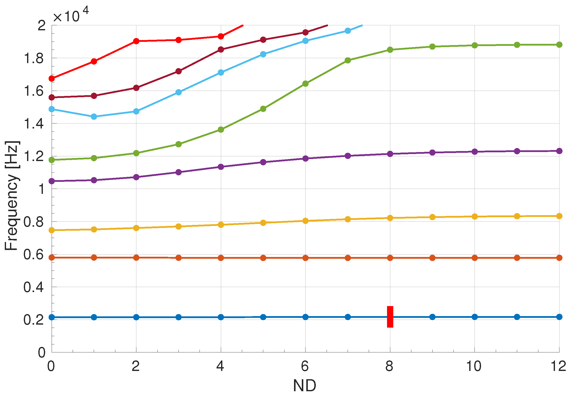
Rotor A is shown in Figure 2, and its diagram for the tuned modes, frequency versus nodal diameter (ND), is presented in Figure 3. The forcing of the first modal family is analysed, with an engine order . The forcing has been normalised to have maximum response amplitude equal to 1 for the tuned rotor.
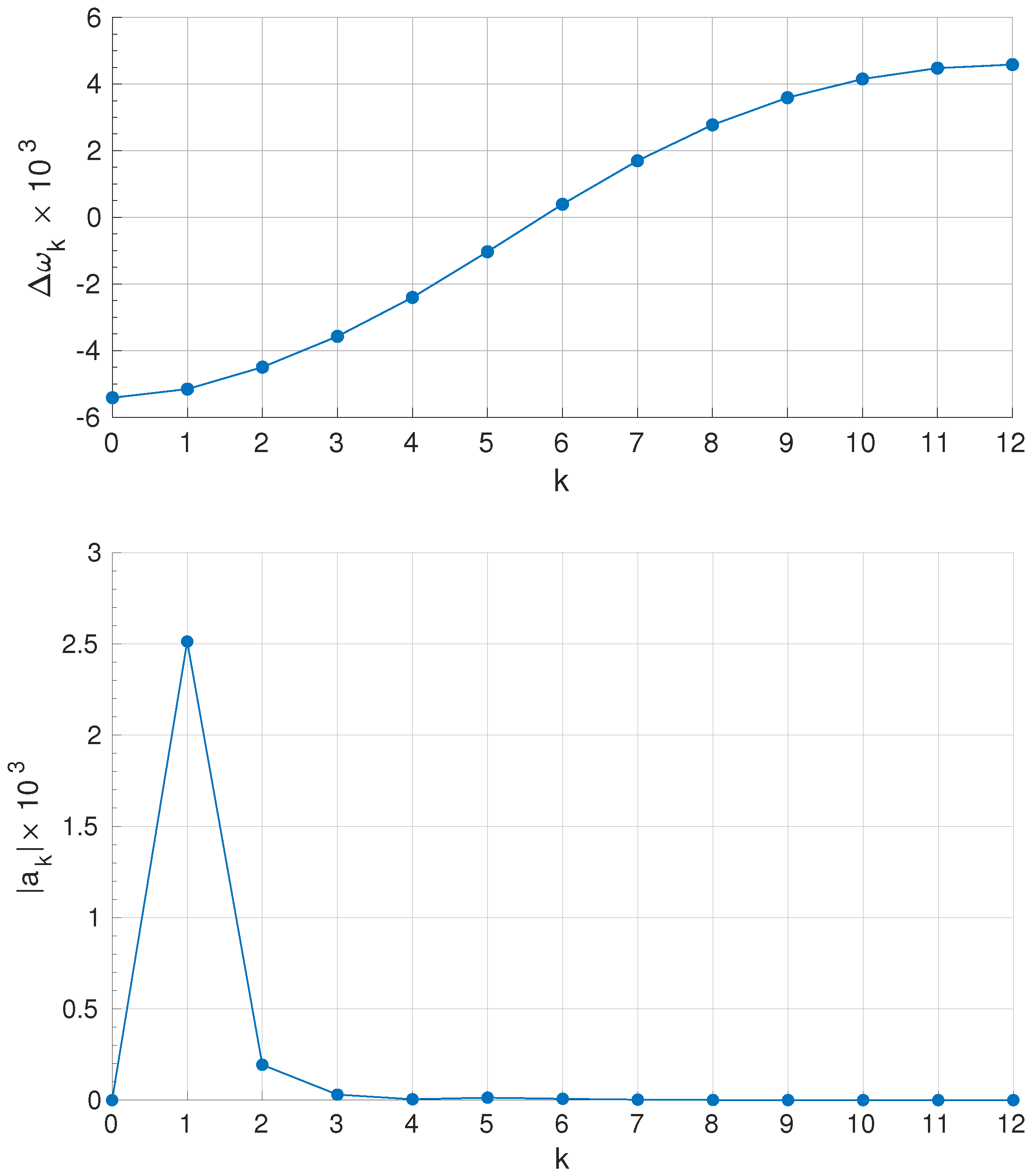
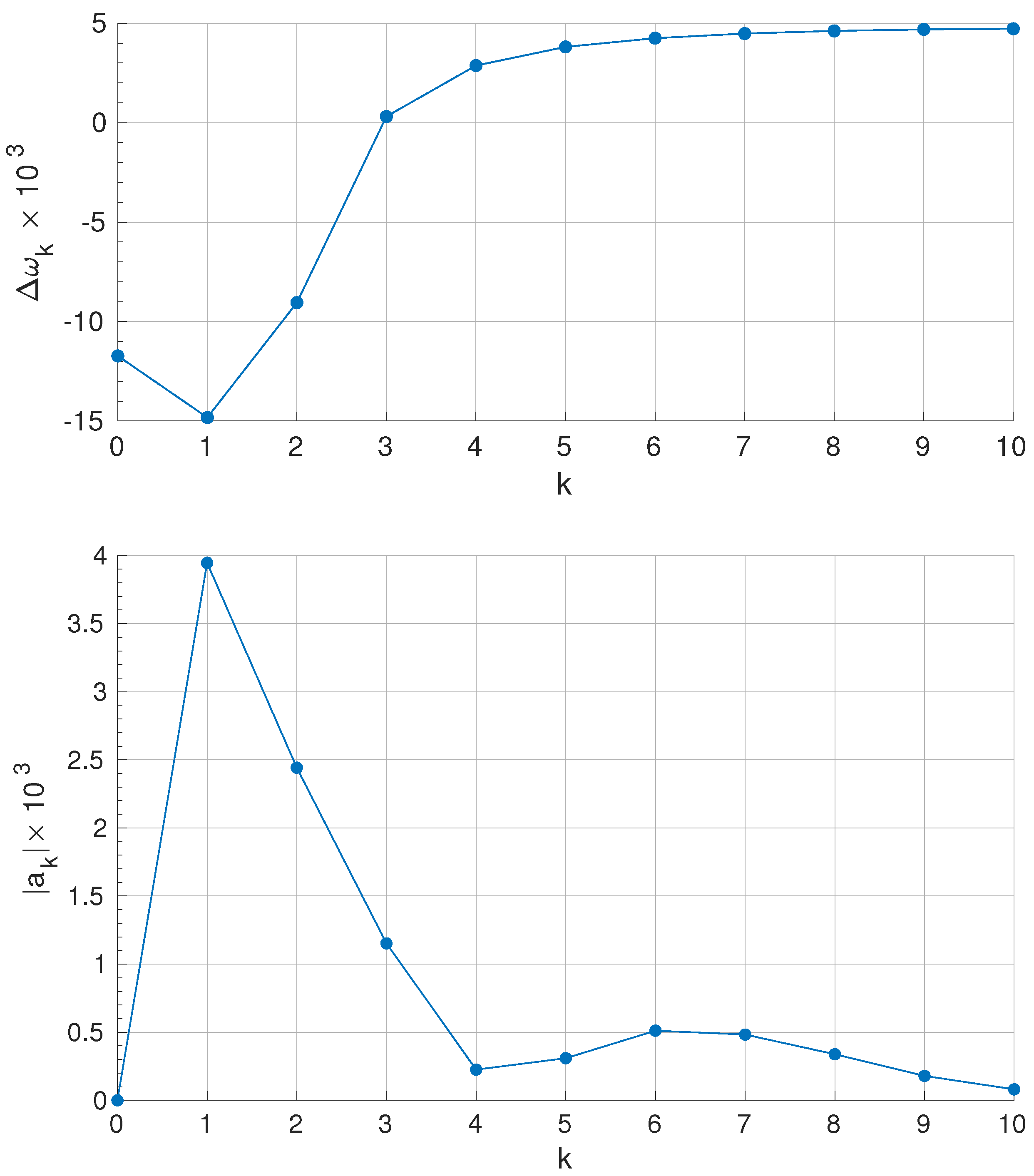
The relative variation of the first family modal frequencies with respect to the average frequency what is actually plotted is represented in the top plot of Figure 4. The corresponding influence coefficients associated with the elastic coupling (the inverse Fourier transform of the distribution) are shown in the lower plot. Both curves are symmetric so only one half is plotted.
It can be clearly seen in Figure 4 that the main coupling comes from the coefficient , which corresponds to the coupling of one blade with the directly adjacent ones (see Figure 1). In this case, following the ideas extracted from the AMM analysis, an alternate mistuning pattern is expected to produce optimal attenuation of the vibration.
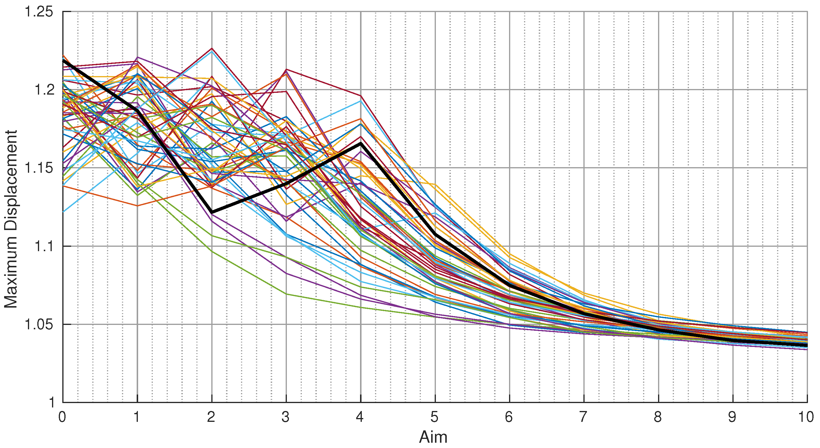
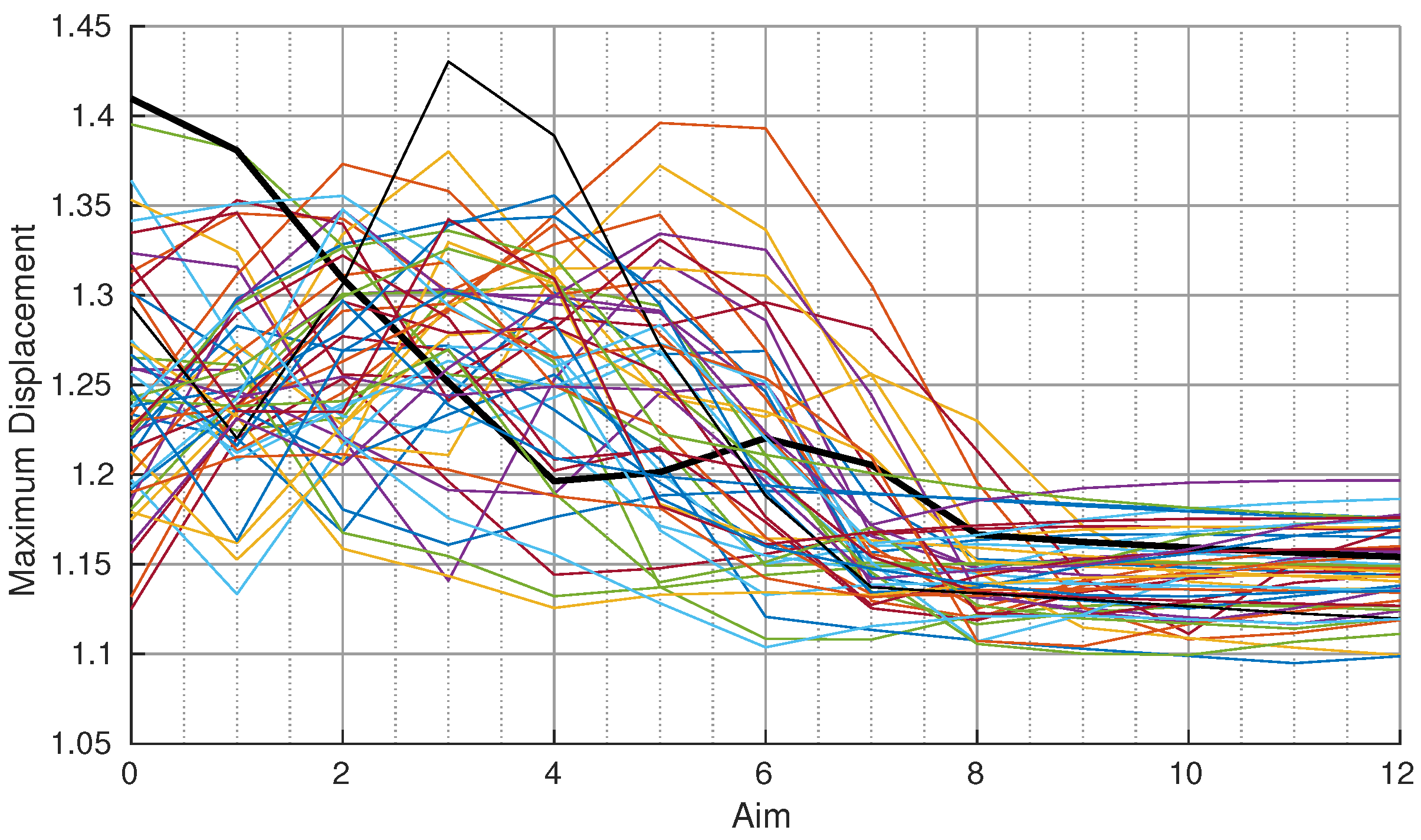
In order to validate this result a significant number of simulations have been carried out. A total of 50 mistuning distributions have been tested, all of them composed of a random pattern with zero average and maximum amplitude , and an alternate mistuning pattern with amplitude in the range 0–10%. The material damping is set to , which is much larger than the remaining coupling coefficients once is cancelled by the alternate mistuning pattern (see Figure 4).
The resulting vibration amplitude for the 50 different mistuning patterns is presented in Figure 5. It can be seen how the vibration amplitude is reduced to the tuned value as the amplitude of the intentional mistuning is increased from to . The sensitivity to the random mistuning is also strongly attenuated, as predicted by the AMM theory in Section 2.1.
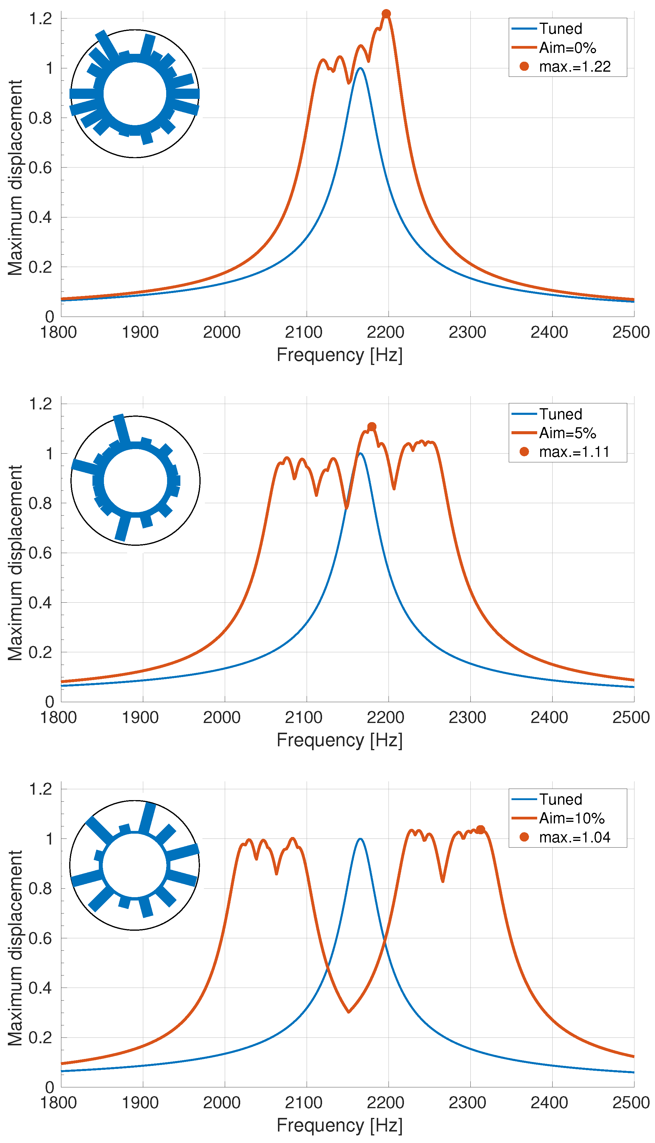
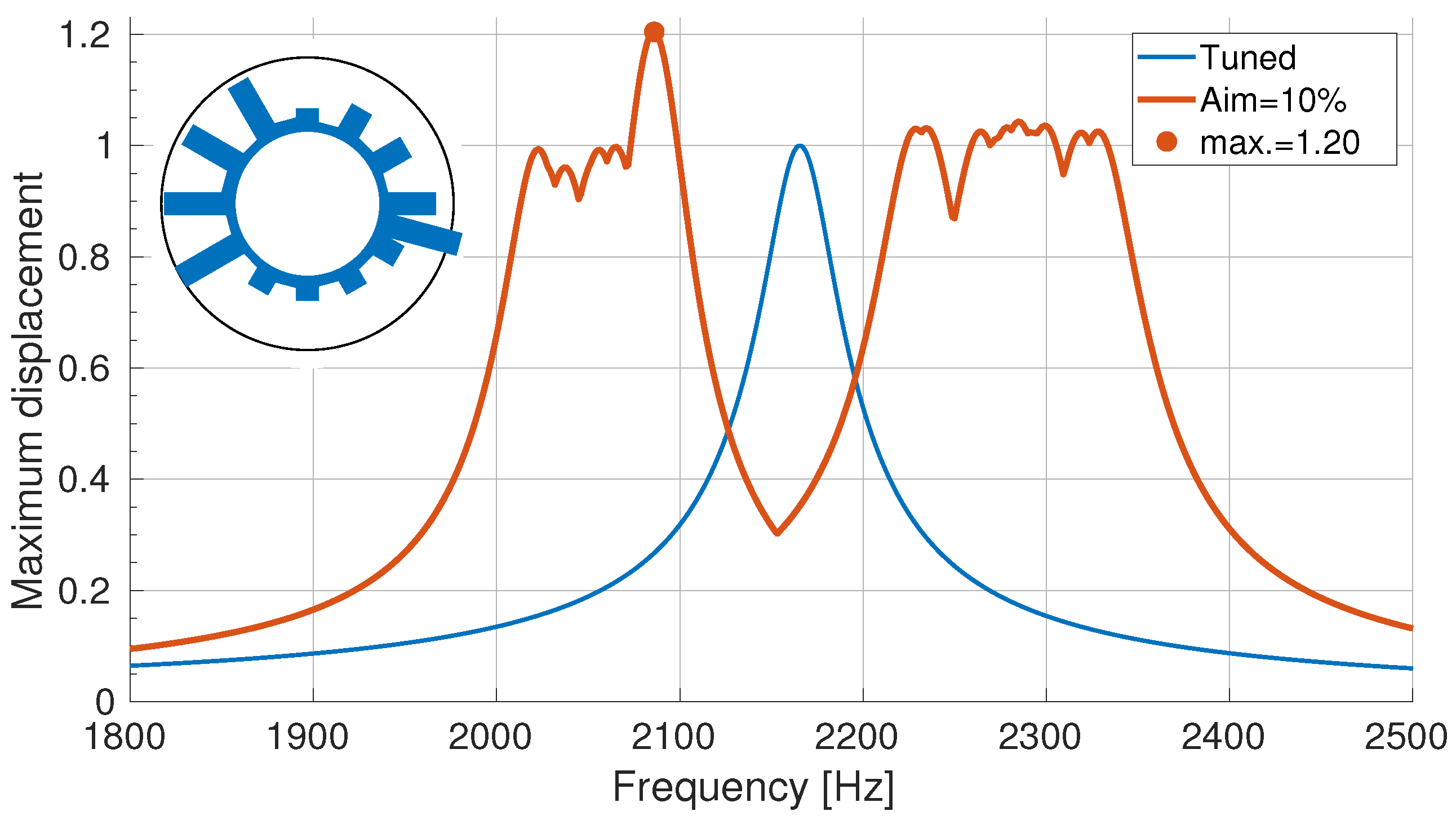
The frequency sweeps and the maximum blade displacements for one random mistuned patterns (marked with a thick line in Figure 5) is represented in Figure 6. As the amplitude of the intentional mistuning grows there is a split in the resonance curve into two peaks, one for the odd and one for the even blades, and the amplification of the vibration is decreased. In the case of (bottom plot), the even and odd blades are effectively decoupled and, at the maximum, only the even blades have a significative vibration amplitude.
3.2. Effect of Relative Size of Damping-Coupling
As was mentioned in Section 2.1, for the intentional mistuning pattern to be effective, the damping must be large as compared to the remaining coupling among the resulting blades of the same type. In order to highlight the importance of this point, the same calculations of the previous section have been repeated but with the material damping reduced to ; a value comparable to the remaining coupling coefficient (see Figure 4). Figure 7 shows the corresponding vibration amplitudes. It is clearly seen that (as predicted by the AMM results) there is now almost no beneficial effect from the implementation of the intentional alternate mistuning pattern in this case.
3.3. Importance of the Separation in Frequency of the Adjacent Blades
In order to highlight the importance of the separation in frequency of the adjacent blades, a second mistuning pattern is now implemented that is similar to the alternate but with the last two blades identical:
This pattern leaves three consecutive blades (the first and the two last ones) with the same intentional mistuning, that is, three consecutive blades that are not separated in frequency. The damping is kept at the same value as before, , and the same 50 random mistuning patterns are used for the computation of the forced response. The results are presented in Figure 8, which shows no reduction of the vibration amplitude, and a much larger sensitivity to random mistuning than in the previous case. The frequency sweep in Figure 9 correspond to a random pattern with high vibration amplitude (thick line in Figure 8). It can be appreciated that, as expected, the maximum displacement takes place at the three consecutive identical blades (located at right most side of the rotor), that are coupled through the disk and can amplify their vibration.
4. Beyond Alternate Mistuning Pattern
Rotor B has sectors and is shown in Figure 10. The frequency versus nodal diameter (ND) diagram for the tuned modes is plotted in Figure 11, with the forcing of the first modal family indicated.
We are now to design an intentional mistuning pattern for rotor B, and validate its effectiveness computing the forced response for 50 random mistuning distributions, with zero average and maximum amplitude , and with the material damping is set to .
In order to design an effective intentional mistuning pattern for rotor B, we look at the elastic coupling influence coefficients for the first modal family presented in Figure 12.
In this case the coupling coefficients and have both a value that is not negligible as compared to the material damping . Following the AMM theory, an effective intentional mistuning pattern should separate one blade from its two adjacent ones in order to remove the effect of the coupling induced by the coefficients and . The intentional mistuning pattern selected is then . The resulting maximum vibration amplitude for increasing intentional mistuning amplitude is shown in Figure 13.
Again, the intentional mistuning pattern is effective: it clearly reduces the vibration amplification and the sensitivity to random mistuning.
This pattern is less effective than the alternate pattern for Rotor A (see Figure 5) because: (i) the difference in terms of intentional mistuning between adjacent blades was for the alternate pattern and now is smaller, only , and (ii) the remaining coupling coefficients after applying the intentional mistuning pattern have now higher amplitude (compare in Figure 12 with in Figure 4).
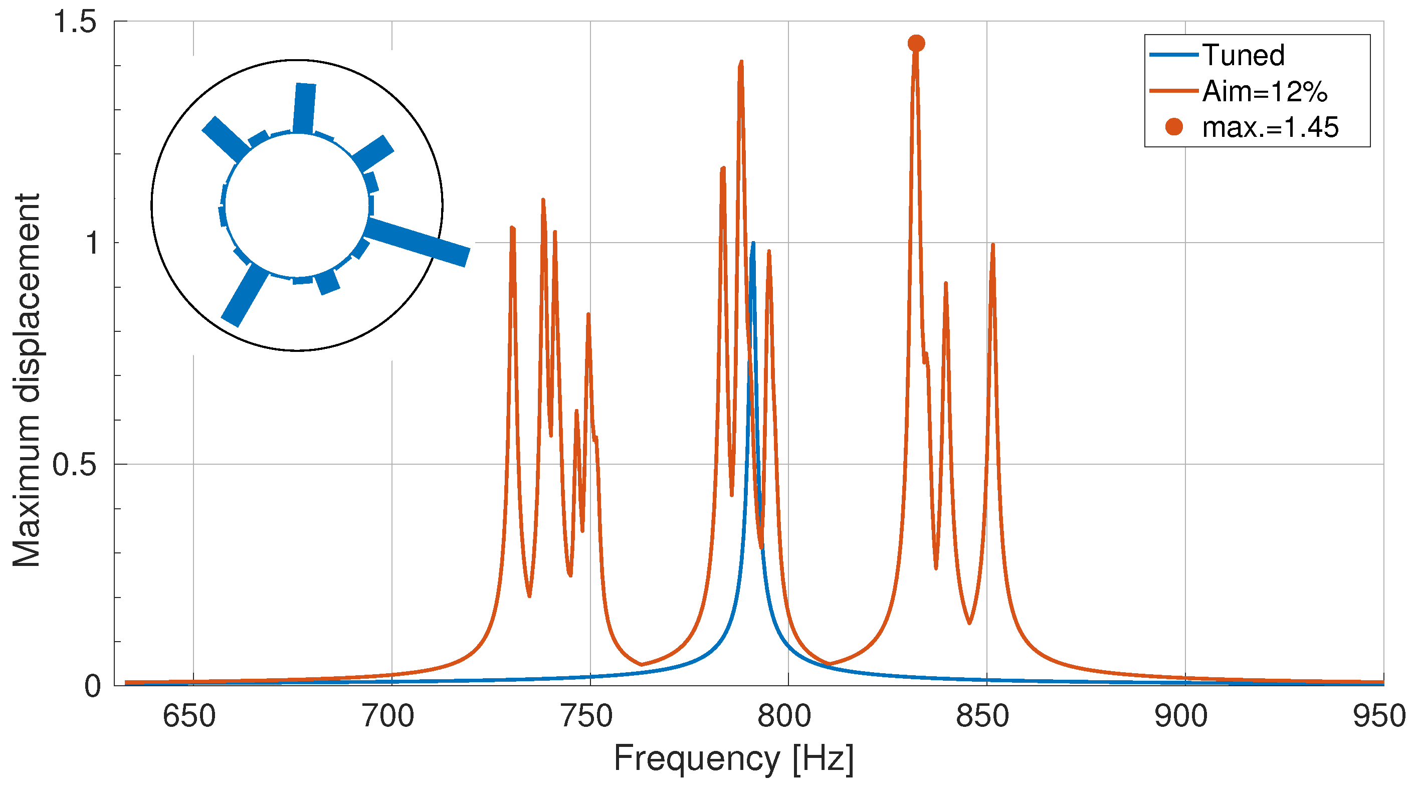
The frequency sweeps corresponding to the random pattern marked with a thick line in Figure 13 are shown in Figure 14. The main difference with the case of the alternate mistuning pattern is that, for large intentional mistuning, the resonance curve is now split into three peaks, and the blade displacement at the maximum shows larger motion in one blade out of every three, indicating that there are three types of blades decoupled by the intentional mistuning pattern.
In order to evidence again the importance of the relative value of the damping compared to the remaining coupling coefficient , a new set of forced response simulations is performed on Rotor B leaving unchanged all parameters except for the value of the material damping that is reduced to . Note that the material damping is now comparable to the remaining coupling coefficient (see Figure 12), and, therefore, according to the AMM theory, the intentional mistuning pattern is not necessarily going to have any beneficial effects in this case.
The vibration amplitude for this case with reduced material damping is shown in Figure 15. No clear trend of vibration amplitude reduction can be appreciated, and the sensitivity to random mistuning is now much higher than in the previous simulations with larger material damping (Figure 13). The frequency sweep plotted in Figure 16 corresponds to the random mistuning pattern marked with a thick line in Figure 15. It shows now much sharper peaks because of the reduced damping. There is still a frequency split in three groups (blades 1, 0, and ), and only one blade out of three vibrate, but the blade displacements at the maximum are now higher and much more localized; a clear indication that the random mistuning still has a strong effect on the vibration of the blades of each type.
5. Main Results and Conclusions
The application of the AMM methodology allows to understand the way of using intentional mistuning to reduce the vibration amplification and the sensitivity to the unavoidable underlying random mistuning, and the limitations of this strategy. The effective attenuation of the random mistuning effects using intentional mistuning is seen to depend on the relative value of three small effects: elastic coupling of the modal family, blade damping, and the random mistuning amplitude:
- Blades are coupled through the elastic forces. The magnitude of this coupling is measured by the influence coefficients () associated with the frequency deviations of the modal family ();
- The effect of the intentional mistuning is to separate in frequency the different types of blades, reducing the coupling between them;
- In order to attenuate the effect of random mistuning, the intentional mistuning pattern should first separate in frequency those blades that show a high elastic coupling, and then, the damping of the modal family, , should be much larger than the remaining influence coefficients;
- The AMM analysis gives also a very simple expression for the limit value of the maximum vibration amplitude that the blades can experience when the intentional mistuning is effective in uncoupling them:(the tuned vibration amplitude).
- The analysis in [10] considered the case of a rotor with an even number of blades and coupling only with the adjacent blades (only one elastic influence coefficient ). In this situation, the alternate mistuning was always effective in reducing the amplification and the sensitivity to random mistuning, independently of the magnitude of the damping.
Author Contributions
The authors contributed equally to this work. Both authors have read and agreed to the published version of the manuscript.
Funding
Spanish Ministerio de Economía, Industria y Competitividad.
Institutional Review Board Statement
Not applicable.
Informed Consent Statement
Not applicable.
Data Availability Statement
Not applicable.
Acknowledgments
The authors wish to thank B. Epureanu and O. Khemiri for providing us with the FEM models of the blisks. This work has been supported by the Spanish Ministerio de Economía, Industria y Competitividad under grant DPI2017-84700-R.
Conflicts of Interest
The authors declare no conflict of interest.
References
- Castanier, M.P.; Pierre, C. Modeling and analysis of mistuned bladed disk status and emerging directions. J. Propuls. Power 2006, 22, 384–396. [Google Scholar] [CrossRef]
- Ewins, D.J.; Chan, Y.J. Vibration of rotating bladed discs: Mistuning, Coriolis, and robust design. In Proceedings of the IUTAM Symposium on Emerging Trends in Rotor Dynamics, New Delhi, India, 23–26 March 2011; Gupta, K., Ed.; Springer: Berlin/Heidelberg, Germany, 2011; pp. 163–175. [Google Scholar]
- Ewins, D.J. The effects of detuning upon the forced vibrations of bladed-disks. J. Sound Vib. 1969, 9, 65–79. [Google Scholar] [CrossRef]
- Castanier, M.; Pierre, C. Investigation of the combined effects of intentional and random mistuning on the forced response of bladed disks. In Proceedings of the Joint Propulsion Conferences, AIAA-98-3720. American Institute of Aeronautics and Astronautics, Cleveland, OH, USA, 13–15 July 1998. [Google Scholar]
- Mignolet, M.P.; Hu, W.; Jadic, I. On the Forced Response of Harmonically and Partially Mistuned Bladed Disks. Part I. J. Rotating Mach. 2000, 6, 29–41. [Google Scholar] [CrossRef] [Green Version]
- Mignolet, M.P.; Hu, W.; Jadic, I. On the Forced Response of Harmonically and Partially Mistuned Bladed Disks. Part II. J. Rotating Mach. 2000, 6, 43–56. [Google Scholar] [CrossRef] [Green Version]
- Castanier, M.P.; Pierre, C. Using intentional mistuning in the design of turbomachinery rotors. AIAA J. 2002, 40, 2077–2086. [Google Scholar] [CrossRef]
- Lim, S.; Castanier, M.P.; Pierre, C. Intentional mistuning design space reduction based on vibration energy flow in bladed disks. ASME 2004, 41715, 373–384. [Google Scholar]
- Han, Y.; Murthy, R.; Mignolet, M.P.; Lentz, J. Optimization of intentional mistuning patterns for the mitigation of the effects of random mistuning. J. Eng. Gas Turbines Power 2014, 136, 062505. [Google Scholar] [CrossRef]
- Campobasso, M.S.; Giles, M.B. Analysis of the effect of mistuning on turbomachinery aeroelasticity. In Proceedings of the 9th International Symposium on Unsteady Aerodynamics, Aeroacoustics and Aeroelasticity of Turbomachines (ISUAAAT 2000), Moscow, Russia, 4–8 September 2000; Ferrand, P., Ed.; Staphane Aubert (Presses Universitaires de Grenoble): Grenoble, France, 2000; pp. 885–896. [Google Scholar]
- Martel, C.; Corral, R. Asymptotic description of maximum mistuning amplification of bladed disk forced response. J. Eng. Gas Turbines Power 2009, 131, 022506. [Google Scholar] [CrossRef]
- Khemiri, O.; Martel, C.; Corral, R. Forced response of mistuned bladed disks: Asymptotic description and FEM validation. AIAA J. Propuls. Power 2013, 30, 397–406. [Google Scholar] [CrossRef] [Green Version]
- Martel, C.; Sánchez-Álvarez, J.J. Maximum mistuning amplification of the forced response vibration of turbomachinery rotors in the presence of aerodynamic damping. J. Sound Vib. 2017, 397, 108–122. [Google Scholar] [CrossRef] [Green Version]
- Feiner, D.M.; Griffin, J.H. A Fundamental Model of Mistuning for a Single Family of Modes. J. Turbomach. 2002, 124, 597–605. [Google Scholar] [CrossRef]
Figure 1.
Sketch of the lumped system (recall that .

Figure 2.
Rotor A with 24 blades and approximately 5800 DOF per sector.

Figure 3.
Rotor A natural vibration frequencies. Red thick line indicates the forcing case considered with engine order .
Figure 3.
Rotor A natural vibration frequencies. Red thick line indicates the forcing case considered with engine order .

Figure 4.
(Top): relative frequency deviations for the first modal family of Rotor A. (Bottom): corresponding influence coefficients.
Figure 4.
(Top): relative frequency deviations for the first modal family of Rotor A. (Bottom): corresponding influence coefficients.

Figure 5.
Maximum vibration amplitude for increasing intentional mistuning amplitude for 50 random mistuning patterns. Rotor A, alternate pattern, .
Figure 5.
Maximum vibration amplitude for increasing intentional mistuning amplitude for 50 random mistuning patterns. Rotor A, alternate pattern, .

Figure 6.
Frequency sweep and (inset) blade displacement at the maximum (black line corresponds to the tuned amplitude), for (top), (middle), and (bottom). Rotor A, alternate pattern, .
Figure 6.
Frequency sweep and (inset) blade displacement at the maximum (black line corresponds to the tuned amplitude), for (top), (middle), and (bottom). Rotor A, alternate pattern, .

Figure 7.
Maximum vibration amplitude for increasing intentional mistuning amplitude for 50 random mistuning patterns. Rotor A, alternate pattern, .
Figure 7.
Maximum vibration amplitude for increasing intentional mistuning amplitude for 50 random mistuning patterns. Rotor A, alternate pattern, .

Figure 8.
Maximum vibration amplitude for increasing intentional mistuning amplitude for 50 random mistuning patterns. Rotor A, pattern, .
Figure 8.
Maximum vibration amplitude for increasing intentional mistuning amplitude for 50 random mistuning patterns. Rotor A, pattern, .

Figure 9.
Frequency sweep and (inset) blade displacement at the maximum (black line corresponds to the tuned amplitude) for . Rotor A, pattern, .
Figure 9.
Frequency sweep and (inset) blade displacement at the maximum (black line corresponds to the tuned amplitude) for . Rotor A, pattern, .

Figure 10.
Rotor B with 21 blades and approximately 3600 DOF per sector: (a) Blisk model. (b) Sector mesh.
Figure 10.
Rotor B with 21 blades and approximately 3600 DOF per sector: (a) Blisk model. (b) Sector mesh.

Figure 11.
Rotor B natural vibration frequencies. Red thick line indicates the forcing case considered with engine order .
Figure 11.
Rotor B natural vibration frequencies. Red thick line indicates the forcing case considered with engine order .

Figure 12.
(Top): relative frequency deviations for the first modal family of Rotor B. (Bottom): corresponding influence coefficients.
Figure 12.
(Top): relative frequency deviations for the first modal family of Rotor B. (Bottom): corresponding influence coefficients.

Figure 13.
Maximum vibration amplitude for increasing intentional mistuning amplitude for 50 random mistuning patterns. Rotor B, pattern, .
Figure 13.
Maximum vibration amplitude for increasing intentional mistuning amplitude for 50 random mistuning patterns. Rotor B, pattern, .

Figure 14.
Frequency sweep and (inset) blade displacement at the maximum (black line corresponds to the tuned amplitude), for (top), (middle), and (bottom). Rotor B, pattern, .
Figure 14.
Frequency sweep and (inset) blade displacement at the maximum (black line corresponds to the tuned amplitude), for (top), (middle), and (bottom). Rotor B, pattern, .

Figure 15.
Maximum vibration amplitude for increasing intentional mistuning amplitude for 50 random mistuning patterns. Rotor B, pattern, .
Figure 15.
Maximum vibration amplitude for increasing intentional mistuning amplitude for 50 random mistuning patterns. Rotor B, pattern, .

Figure 16.
Frequency sweep and (inset) blade displacement at the maximum (black line corresponds to the tuned amplitude), . Rotor B, pattern, .
Figure 16.
Frequency sweep and (inset) blade displacement at the maximum (black line corresponds to the tuned amplitude), . Rotor B, pattern, .

Publisher’s Note: MDPI stays neutral with regard to jurisdictional claims in published maps and institutional affiliations. |
© 2021 by the authors. Licensee MDPI, Basel, Switzerland. This article is an open access article distributed under the terms and conditions of the Creative Commons Attribution (CC BY) license (https://creativecommons.org/licenses/by/4.0/).
Share and Cite
MDPI and ACS Style
Sánchez-Álvarez, J.J.; Martel, C. Key Action Mechanisms of Intentional Mistuning. Appl. Sci. 2021, 11, 5650. https://0-doi-org.brum.beds.ac.uk/10.3390/app11125650
AMA Style
Sánchez-Álvarez JJ, Martel C. Key Action Mechanisms of Intentional Mistuning. Applied Sciences. 2021; 11(12):5650. https://0-doi-org.brum.beds.ac.uk/10.3390/app11125650
Chicago/Turabian StyleSánchez-Álvarez, Jose Joaquin, and Carlos Martel. 2021. "Key Action Mechanisms of Intentional Mistuning" Applied Sciences 11, no. 12: 5650. https://0-doi-org.brum.beds.ac.uk/10.3390/app11125650
Note that from the first issue of 2016, this journal uses article numbers instead of page numbers. See further details here.