
A Thermal Transport Study of Branched Carbon Nanotubes with Cross and T-Junctions


Department of Mechanical Engineering, National Cheng Kung University, Tainan 70101, Taiwan
*
Author to whom correspondence should be addressed.
Appl. Sci. 2021, 11(13), 5933; https://0-doi-org.brum.beds.ac.uk/10.3390/app11135933
Submission received: 28 April 2021
/
Revised: 17 June 2021
/
Accepted: 20 June 2021
/
Published: 25 June 2021
(This article belongs to the Topic Advances and Applications of Carbon Nanotubes)
Abstract
:Featured Aplication
Our findings provide deep insights into the thermal transport mechanisms of branched carbon nanotubes, which may be useful in thermal management applications.
Abstract
This study investigated the thermal transport behaviors of branched carbon nanotubes (CNTs) with cross and T-junctions through non-equilibrium molecular dynamics (NEMD) simulations. A hot region was created at the end of one branch, whereas cold regions were created at the ends of all other branches. The effects on thermal flow due to branch length, topological defects at junctions, and temperature were studied. The NEMD simulations at room temperature indicated that heat transfer tended to move sideways rather than straight in branched CNTs with cross-junctions, despite all branches being identical in chirality and length. However, straight heat transfer was preferred in branched CNTs with T-junctions, irrespective of the atomic configuration of the junction. As branches became longer, the heat current inside approached the values obtained through conventional prediction based on diffusive thermal transport. Moreover, directional thermal transport behaviors became prominent at a low temperature (50 K), which implied that ballistic phonon transport contributed greatly to directional thermal transport. Finally, the collective atomic velocity cross-correlation spectra between branches were used to analyze phonon transport mechanisms for different junctions. Our findings deeply elucidate the thermal transport mechanisms of branched CNTs, which aid in thermal management applications.
1. Introduction
Since the discovery of carbon nanotubes (CNTs) in 1991, considerable research has been conducted on their mechanical, optical, and electronic properties. CNTs have been proposed as the most promising building blocks for nanoelectronic devices and thermal management applications due to their high thermal conductivity and mechanical stability [1,2]. However, the quasi-one-dimensional thermal transport of CNTs has restricted their applications. Therefore, branched CNTs [3,4] have been proposed as alternatives to CNTs. Due to their strong sp2 covalent bonds, branched CNTs exhibit lower thermal resistance than those structures with van der Waals interactions (e.g., CNT bundles [5,6], intermolecular junctions [7,8,9], and CNT networks [10,11]). In addition, high-quality and high-purity branched CNTs have been synthesized using various approaches [12,13,14,15,16,17,18]. Moreover, branched CNTs demonstrate potential in rectifying electrical currents [12,13,14] and heat [3,19]. Therefore, the thermal transport behavior inside branched CNTs should be investigated to identify their possible applications.
Molecular dynamic (MD) simulation is an appropriate tool for characterizing the collective and individual behavior of atomics or molecules at the nanoscale level. Compared with other atomistic methods, such as the use of Boltzmann transport equations, lattice dynamics, and non-equilibrium Green’s function, MD simulation can more accurately capture the dynamics of lattice vibration, including harmonic and anharmonic interactions [20]. MD simulations have been widely adopted to investigate the thermal transport mechanisms of pristine CNTs. A frequently researched aspect of pristine CNTs is their length-dependent thermal conductivity, which involves ballistic or diffusive phonon transport behavior at varying lengths [21,22,23]. However, similar examinations on the phonon transport mechanism or thermal energy transfer inside branched CNTs have rarely been conducted. Branched CNTs possess topological defects and the possibility of multi-directional thermal transfer in junction regions, whereas pristine CNTs do not. Some studies have examined the influences of the aforementioned phenomena on the thermal transport behavior [3,4,24,25,26]. The topological defects at the junction area of branched CNTs must satisfy Euler’s polyhedral formula [27,28]. Topological defects often cause considerable phonon scattering and thus an increase in thermal resistance, which subsequently influences heat transfer [24,26]. Moreover, the connections of different carbon structures, such as CNTs and graphene, must facilitate multi-directional thermal transfer; however, dimensional mismatch occurs at the junction, which causes an increase in resistance, a decrease in transmission, and changes in the incident phonon mode [24,29,30].
Some researchers have investigated thermal ratification behaviors for branched CNTs by conducting experiments [19], heat pulse simulations [3], and wave packet simulations [4]. Chen et al. [31] investigated the thermal transfer inside a branched CNT with T-junctions and observed that the heat preferred to flow straight rather than sideways, especially for short branch lengths. They also noticed that symmetric temperature setups exhibited lower transmission than asymmetric temperature setups because the phonons were forced to change their propagation directions in the symmetric temperature setups. The aforementioned phenomenon has been attributed to the occurrence of ballistic phonon transport and topological defects (i.e., heptagons and octagons). However, the underlying dominant mechanisms of the directional heat transfer inside branched CTNs have yet to be determined.
In the present study, the heat flow inside branched CNTs with cross and T-junctions was investigated using non-equilibrium molecular dynamics (NEMD) simulations. The junctions in the CNTs were constructed through thermal welding. All of the CNT branches had the same chirality and length and were attached to the cross and T-junctions to form branched CNTs. The effects on thermal transfer due to branch length, topological defects at the junction, and temperature were studied. Moreover, the collective atomic velocity cross-correlation spectra between branches were used to analyze the phonon transport mechanisms in the branched CNTs.
2. Methodology
All NEMD simulations were conducted using the Large-scale Atomic/Molecular Massively Parallel Simulator (LAMMPS) package [32]. The adaptive intermolecular reactive bond order (AIREBO) potential [33] was employed in this study to describe the interatomic interaction between carbon atoms. T-junctions and cross-junctions were created using the thermal welding method proposed in [17]. Some atoms were removed intentionally from one pristine 4 nm (6, 6) CNT to create a crossing region. The atoms were removed such that the topological requirement described by the Euler polyhedral formula was satisfied [28]. This formula regulates the numbers of vertices, faces, and edges in a convex three-dimensional polyhedron. The number of pentagons (), heptagons (), and octagons () at a junction must satisfy the following equality: . A 1.5 nm (6, 6) CNT was placed vertically with respect to the crossing region of the defect-containing 4 nm (6, 6) CNT. Subsequently, the two aforementioned CNTs were moved closer and simultaneously heated up to 4000 K to perform thermal welding. A high temperature was adopted to accelerate the creation of interlinks and surface reconstruction. Finally, the T-junction model was cooled to 300 K.
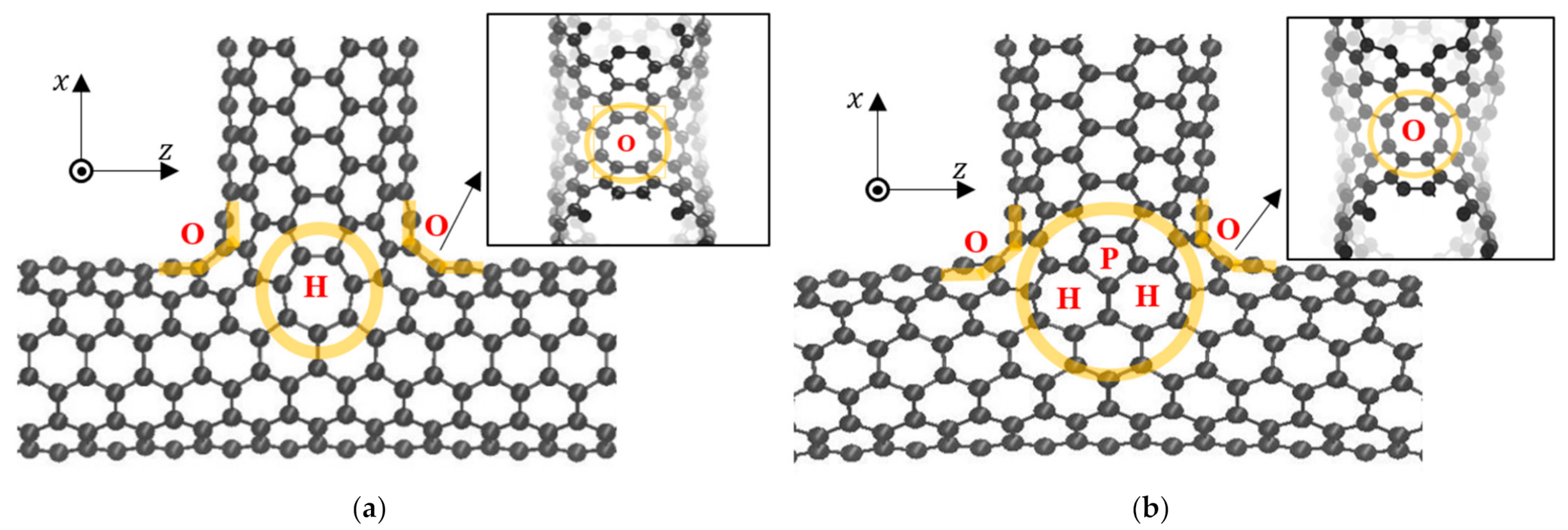
Through the sequential removal of carbon atoms, topological defects in the junction area could be quantitatively controlled to satisfy the Euler polyhedral formula. Thus, T-junctions with two atomic configurations containing different topological defects were constructed, as illustrated in Figure 1a,b. One atomic configuration, which is hereafter referred to as T-junction 1, contained two heptagon rings (one in the back) and two octagons in the corner region, as depicted in Figure 1a. The second atomic configuration, which is hereafter referred to as T-junction 2, contained four heptagon rings (two in the back), two pentagon rings (one in the back), and two octagons in the corner region, as depicted in Figure 1b.
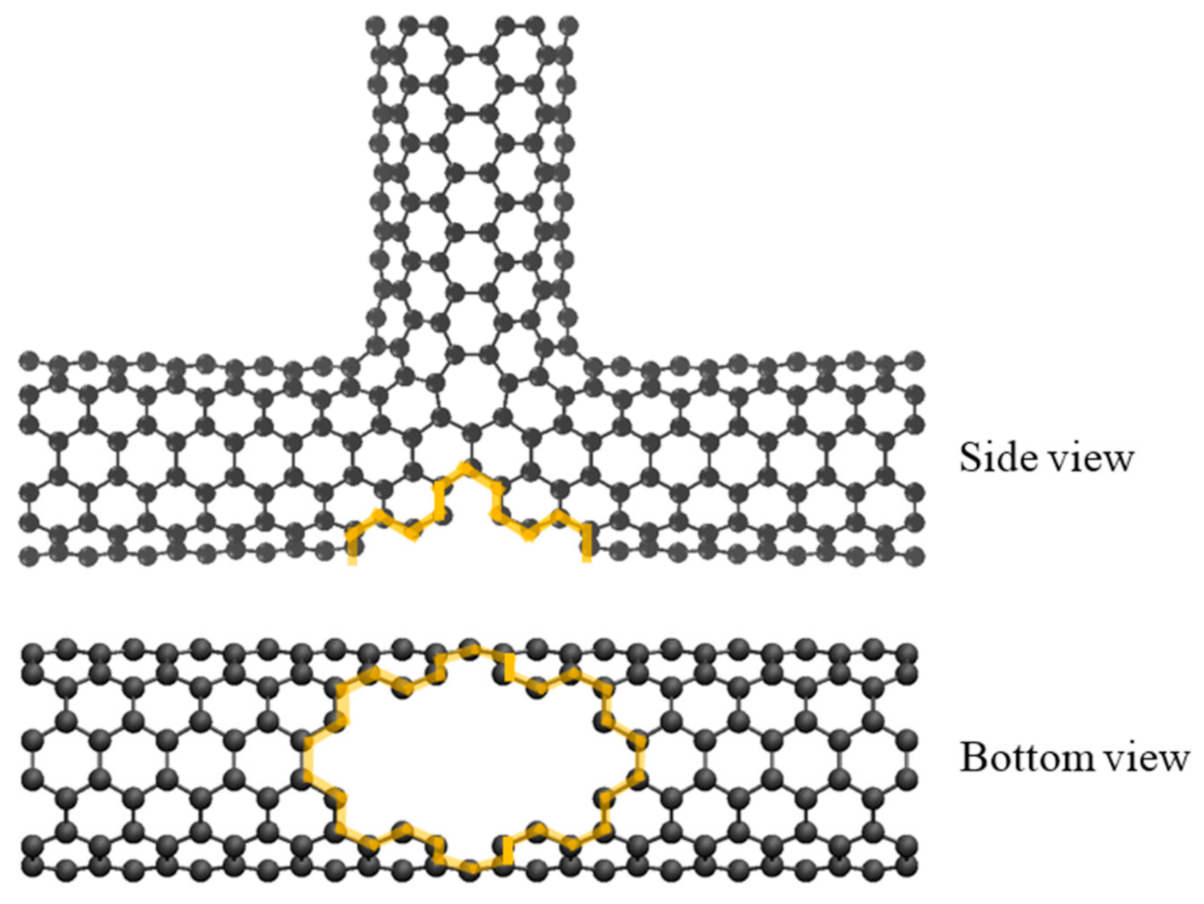
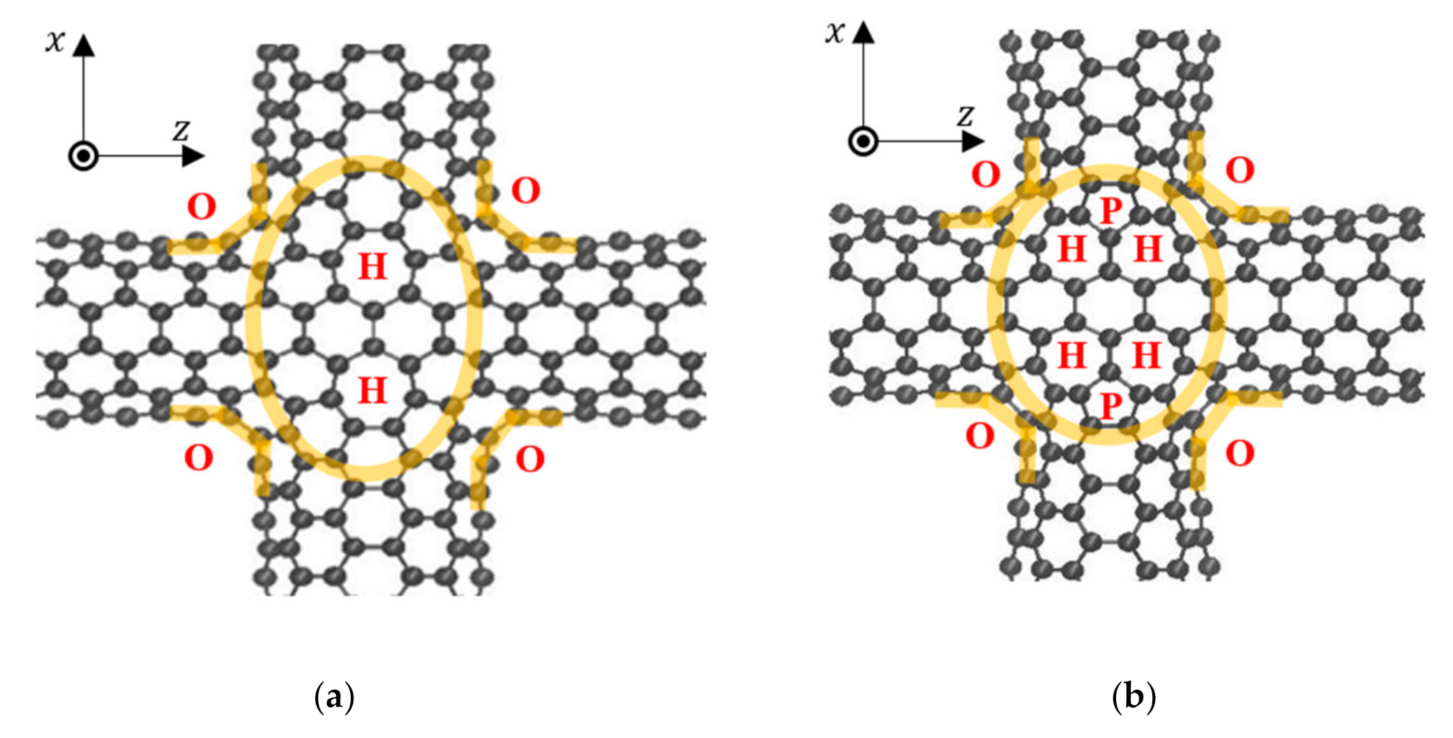
Cross-junctions were constructed by further removing atoms from the bottom region of the T-junction model, which is hereafter referred to as the defect-containing T-junction, as illustrated in Figure 2. For symmetry, the atoms removed from the bottom of the aforementioned model were the same as those in the top crossing region of this model. A 1.5 nm (6, 6) CNT was assembled with the defect-containing T-junction model by using the thermal welding process to form cross-junctions, as depicted in Figure 3a,b. The cross-junction models depicted in Figure 3a,b were called cross-junctions 1 and 2, respectively. The cross-junction models had twice the number of topological defects that their T-junction counterparts did.
Equal-length (6, 6) CNTs were connected to T-junctions and cross-junctions to form branched CNTs. To investigate the effect of branch length on the heat flow inside the branched CNTs, various branch lengths between 25 and 200 nm were considered for the simulations. The entire system was relaxed using a canonical (NVT) ensemble at the junction region under a temperature of 300 K. The time step used for all simulations was 1 fs. To release the stress inside branched CNTs, the atoms on each individual branch were allowed to move only along the axial direction of the CTNs under the microcanonical (NVE) ensemble and the equilibrating process was run for 1 ns. Through the aforementioned relaxation procedure, both longitudinal and transverse stresses inside the branches were eliminated. Relaxing the structure was crucial because the residual stress from the initial model can influence the material properties and can thus affect the heat flow [30].
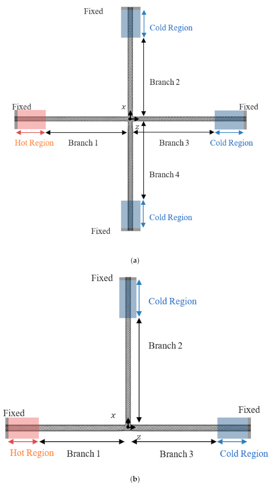
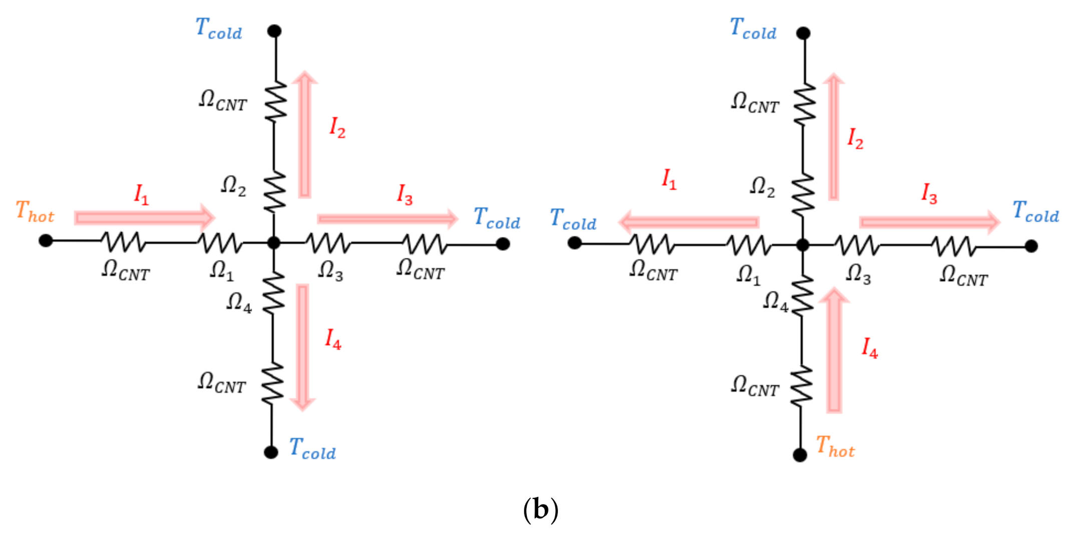
The temperature setups of the cross and T-junctions are displayed in Figure 4a,b, respectively. To avoid rigid body motion (i.e., translational movement and rotation) of the branched CNTs, all of the branches were fixed at their ends for a length of 0.5 nm adjacent to a 5 nm temperature-controlled region. The temperatures in the hot and cold regions were controlled at K by using the Langevin thermostat setting. To observe the thermal flow, a hot region was created at the end of branch 1 of the branched CNTs whereas cold regions were created at all of the other branch ends. The NVE ensemble was implemented in the free area of branched CNTs for 1 ns to enable the heat current to reach a steady state. All of the results were collected in the following 1 ns. Each model was simulated and averaged six times with different initial velocities.
In the branched CNT with cross-junctions, the heat current flowed from branch 1 into the other three branches (branches 2, 3, and 4; Figure 4a). To investigate the heat flow behavior inside this branched CNT, we defined the heat current ratio beyond the junction as follows:
where is the power removed from the temperature-controlled region of branch . The heat current ratio for the T-junctions was similarly defined as that in Equation (1).
3. Results
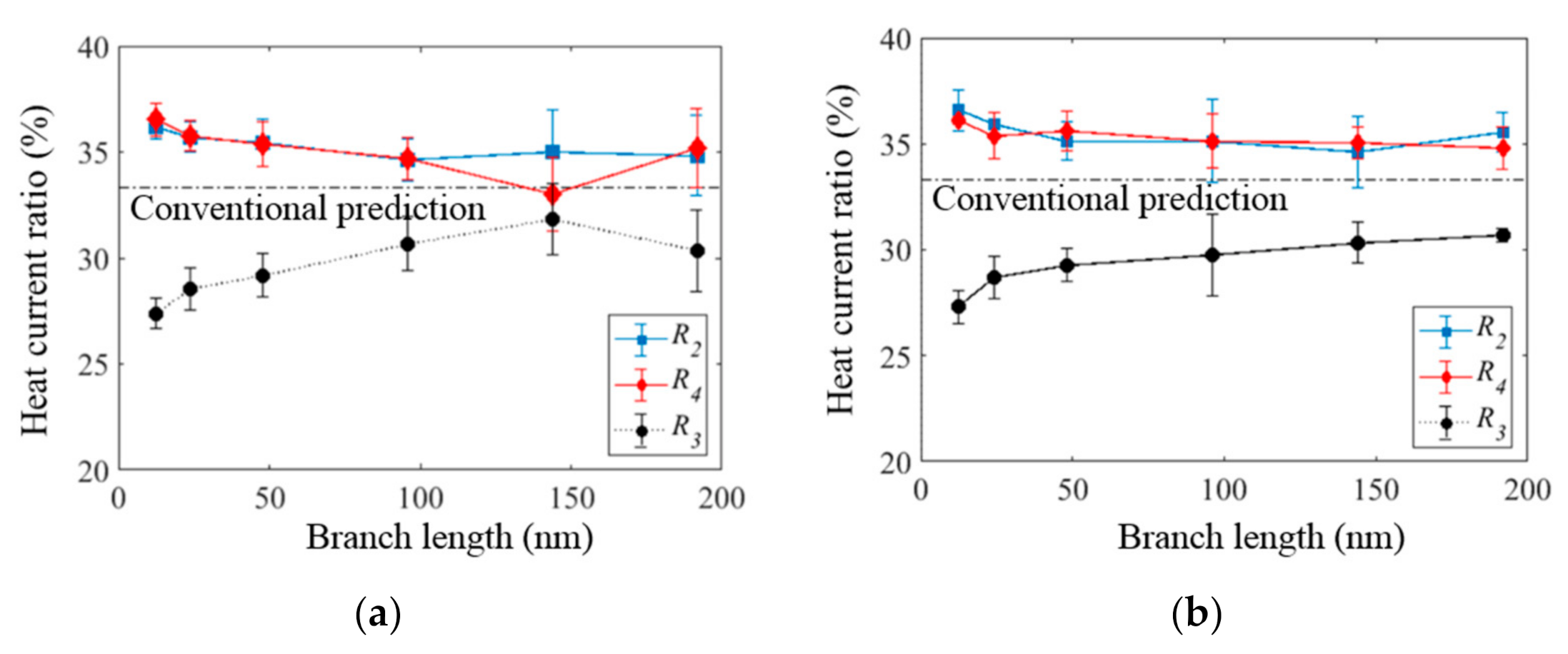
The heat current ratios occurring after the cross and T-junctions were examined through NEMD simulations. The effects of branch length, atomic configurations at the junctions, and temperature on the heat flow inside the branched CNTs were examined. The length dependence of the heat current ratios for the two cross-junctions is illustrated in Figure 5a,b. Regardless of the atomic configuration at the junctions, the heat current ratios and (for branches 2 and 4, respectively) were approximately equal and larger than . This result indicates that the heat currents did not flow equally into the three branches after the junction even though all of the branches had identical length and chirality. The heat flow into the top (branch 2) and bottom (branch 4) branches was higher than that into the straight branch (branch 3), especially for short branch lengths. However, as the branch length increased, the heat current ratio tended to approach . This value was equal to the prediction result obtained using conventional thermal circuit theory under the assumptions that the thermal resistances along all the branch directions at the junction were identical and that the thermal properties of all of the branches were the same.
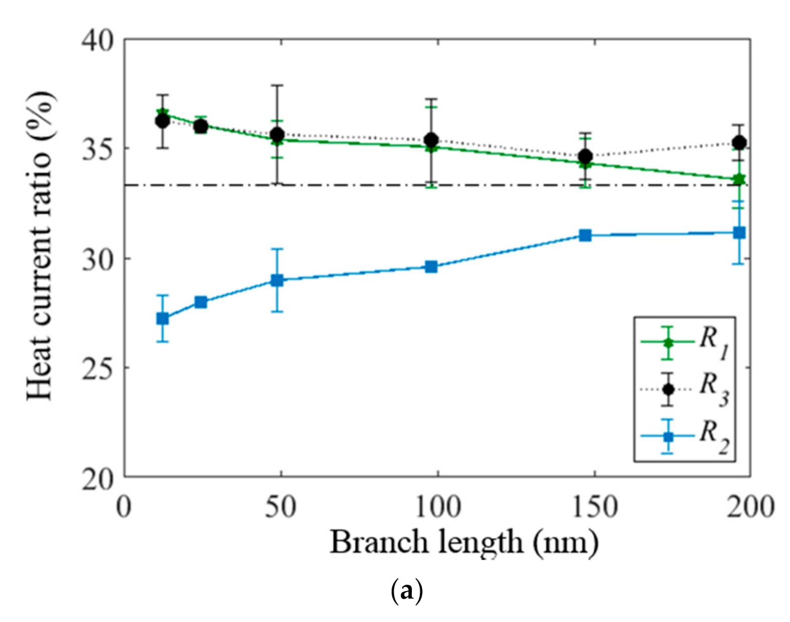
Moreover, the thermal transport behavior was investigated by creating a hot region placed at the bottom branch (branch 4) and cold regions at the ends of the other branches for the branched CNT with cross-junctions. Different temperature settings produced different heat current directions, along which different topological defects were encountered. For instance, the heat current from branch 1 encountered two heptagons in parallel at cross-junction 1; however, the heat flow from branch 4 encountered two heptagons in series. The heat current results for two temperature settings were within the standard deviation error, as shown in Figure 5a and Figure 6a. For both settings, the heat current preferentially flowed sideways rather than straight.
We attempted to explain the aforementioned observations by using thermal circuit theory and by considering the anisotropic thermal conductance at the junction. As the topological defect locations were horizontally (along branches 1 and 3) and vertically (along branches 2 and 4) asymmetric, the thermal resistances at the junctions along the branches may have been different. A previous study [29] indicated that defects in series have lower thermal resistance than those in parallel. When the asymmetric junction resistance is considered (Figure 6b), the temperature difference between the hot and cold regions () (hot region placing at branch 1) can be expressed as follows:
where is the thermal resistance of the pristine CNT branch and is the heat current at branch i. The following expression is obtained:
As the heat currents of branches 2 and 4 were larger than that of branch 3 (, we deduced that the thermal resistance at the junction satisfied the following expression: . However, a contradictory result (i.e., ) was obtained when we considered the heat current situation in which a hot region was created at branch 4. Our simulation results cannot be explained using an account of conventional thermal circuits with or without the consideration of thermally anisotropic junctions. This finding implies that the obtained results cannot be explained simply by diffusive-based thermal circuit theory.
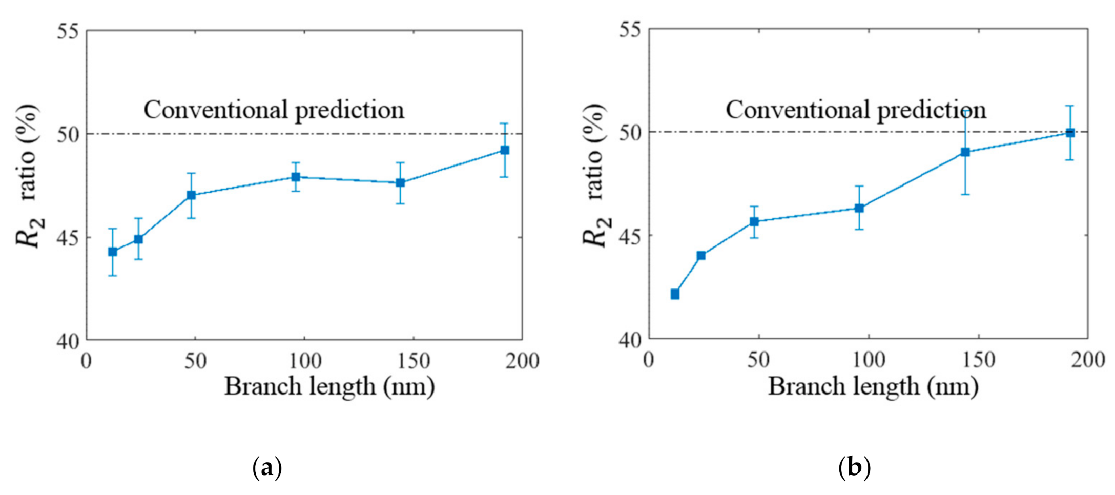
The thermal transport behavior inside the branched CNT with T-junctions was also simulated. The dependences of the heat current ratios on the branch lengths are displayed in Figure 7a,b, respectively. The heat current preferentially flowed straight into the straight branch rather than sideways (i.e., or), especially for the short branch, irrespective of the atomic configurations at the T-junctions. However, as the branch length increased to 200 nm, the heat current ratios of branches 2 and 3 (i.e., and, respectively) approached, which was predicted by a diffusive-based conventional thermal circuit calculation. Similar to the branched CNT with cross-junctions, the atomic defects of pentagonal, heptagonal, and octagonal rings did not influence the directional heat transfer behaviors. Moreover, the heat current preferentially flowed sideways rather than straight, with one additional bottom branch attached to a T-junction.
4. Discussion
Through NEMD simulation of branched CNTs, directional heat transfer on the branches could be observed. The directional heat transfer behavior in branched CNTs can be attributed to two possible causes: asymmetric polygonal rings in the junction regions and ballistic phonon transport [31]. First, it was reported that phonons exhibit different interactions with asymmetric polygon rings, which resulted in directional flow due to the specific location of the polygon rings [29]. This effect became weaker as the branch length increased because the thermal resistance was influenced more by the branches than the junctions. Therefore, heat currents tended to flow equally into each branch at long branch lengths. However, similar heat current results were obtained regardless of the atomic configuration at the junction (Figure 5 (cross-junctions) and Figure 7 (T-junctions)). Even if the configuration of the polygon rings changed (e.g., from two heptagons in parallel to two heptagons in series) by shifting the hot region to the bottom side, the heat still tended to flow sideways rather than straight, as displayed in Figure 6a. Thus, the results indicated that the directional heat transfer in branched CNTs was not dominated by local asymmetric polygonal rings.
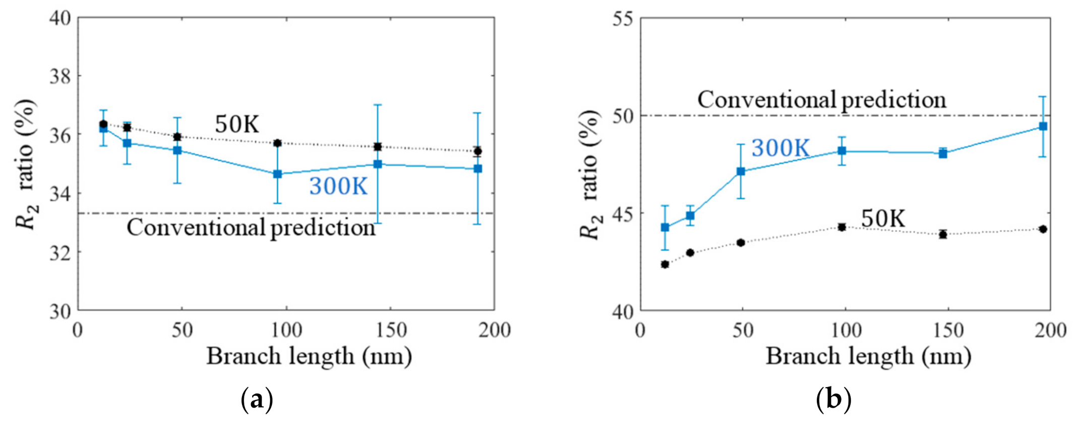
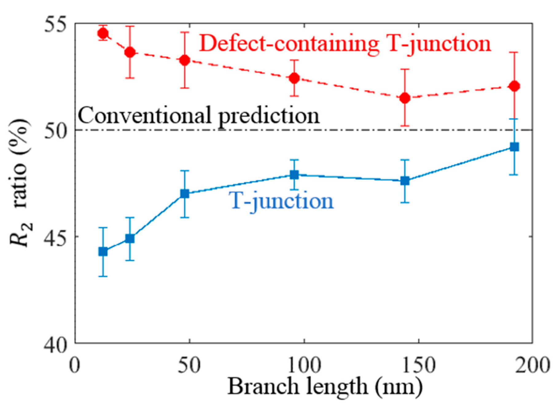
Second, heat may exhibit ballistic transport rather than diffusive scattering inside branched CNTs, especially for short branches. When a branch was longer than the phonon mean free path, ballistic to diffusive crossover of heat flow occurred and the heat was transported predominantly through diffusive scattering; thus, an equal heat current occurred in each branch. As ballistic phonon transport was more pronounced at low temperatures [1,21,34,35], the temperature effect was studied to further investigate the thermal flow mechanism inside branched CNTs with cross and T-junctions. The hot and cold regions were controlled at K to observe how the heat currents between branches changed. As illustrated in Figure 8a,b, the heat current ratios for branch 2 exhibited relatively high deviation from the conventional predictions for both junctions, which indicates the thermal transport mechanisms in these branches were less diffusive and more ballistic at lower temperatures. Moreover, the NEMD simulation was conducted on the branched CNT with a defect-containing T-junction (Figure 2) to examine the different directional thermal flow behaviors between cross and T-junctions. Compared with the T-junction, the defect-containing T-junction, which was the intermediate construction stage of a cross-junction, had an additional opening in its bottom region. As displayed in Figure 9, the size dependence of the heat current ratio in branch 2 of the defect-containing T-junction was similar to that on the size of a cross-junction and completely different from that on the size of the T-junction. It is likely that phonons would scatter by the additional opening at the bottom of defect-containing T-junction. Thus, the presence of an additional opening at the bottom caused the heat current to tend to flow sideways into branch 2 rather than straight into branch 3, which was unlike the phenomenon observed for the T-junction.
Moreover, to analyze the thermal transport mechanism inside the branched CNTs with different junctions, the collective atomic velocity cross-correlation spectra between branches were examined to determine whether the phonons still maintained their original vibrational characteristics after passing the junction structure. First, the power spectrum of velocity cross-correlation between a pair of atoms located in two branches was defined as follows:
where was the atomic velocity along the direction of the th atom at the th unit cell located on branch . The angle in brackets indicates the time moving average. The power spectrum of the time correlation function can provide information on how one atomic vibration was transmitted to another atom in different frequency ranges. As phonons are a collective motion of the periodic elastic arrangement of atoms inside condensed matter, the power spectrum of velocity cross-correlation between a pair of atoms located in two branches was insufficiently informative. Therefore, a group of atoms within unit cells in each branch was selected to calculate the atomic velocity cross-correlation as follows:
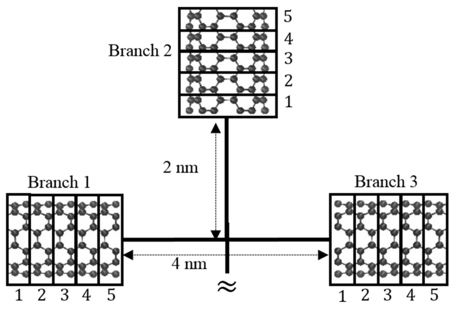
where was the number of atoms in one unit cell. In the conducted analysis, was selected as 5. Moreover, the number of atoms in one unit cell, , for a (6, 6) CNT was 24. Our methodology of velocity cross-correlation was similar to the one adopted to calculate coherence length by Latour et al. [36]. Special care was taken to ensure that the distance between each pair of atoms used to calculate the velocity cross-correlation was the same (Figure 10), which was unlike the method used by Latour et al. [36], to ensure that the time for traveling between the calculated atoms would not be different. Different atomic velocity directions were considered to characterize different phonon modes (i.e., the longitudinal and transverse phonon modes). The longitudinal (transverse) phonon mode was identified when the atoms vibrated parallel (perpendicular) to the branch axial direction. The cross-correlation results were averaged over six different runs.
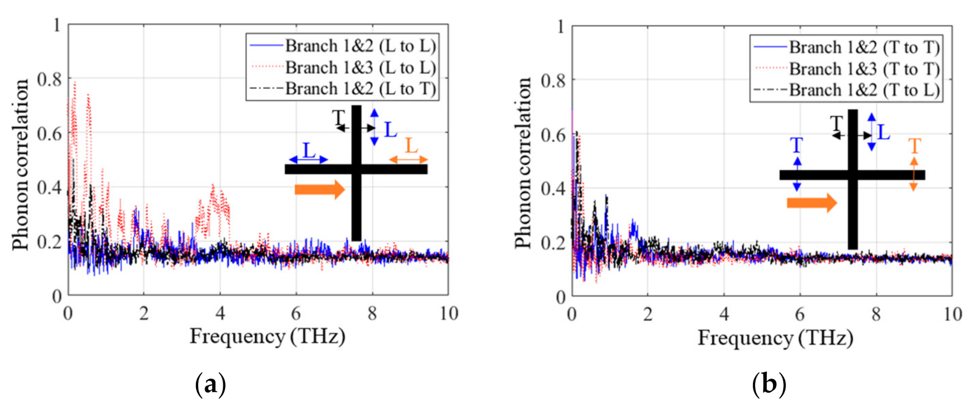
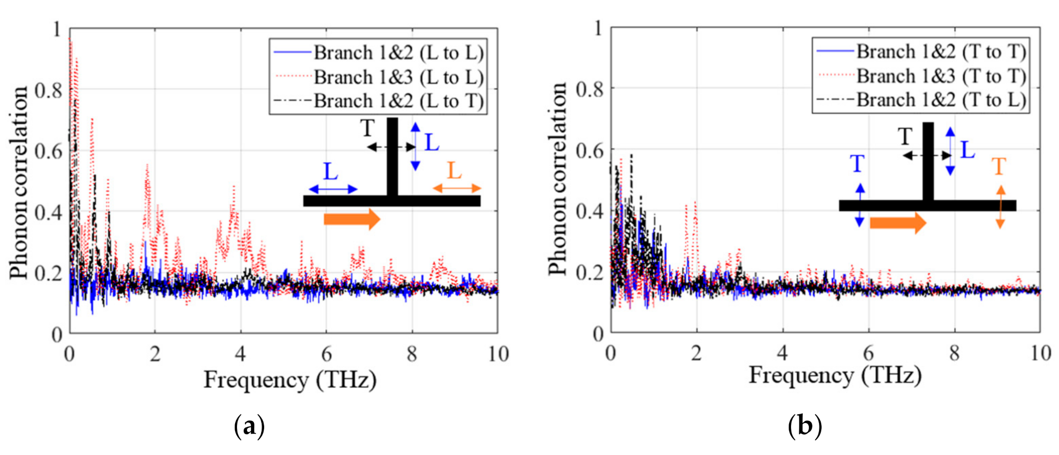
The collective power spectra for the longitudinal and transverse vibrations, which were termed the phonon correlation function, were analyzed for cross-junction 1 (Figure 11) and T-junction 1 (Figure 12). As demonstrated in Figure 11a and Figure 12a, the longitudinal vibrations of branch 1 were more easily transmitted to branch 3 than to branch 2 in both the longitudinal and transverse modes, which indicates that the vibrations in branch 2 originated from scattering and their correlation subsequently reduced. At low frequencies (<1 THz), all of the vibrations between branches exhibited higher correlations, which is consistent with the fact that low-frequency phonons have a long mean free path [36,37]. In addition, the longitudinal vibrations of branch 1 had a higher correlation with the transverse vibration of branch 2 than with the longitudinal vibration of branch 2. This result indicated that the longitudinal phonon may change to a transverse phonon when transported from branch 1 to branch 2. This behavior is similar to the phonon polarization conversion behavior observed by Shi et al. [24,29,30].
As depicted in Figure 11b and Figure 12b, the transverse vibrations of branch 1 exhibited higher transmittance strength in branch 3 for a T-junction than for a cross-junction, especially at a frequency of approximately 2 THz. However, the transverse vibrations of branch 1 had lower overall correlations with the vibrations of branches 2 and 3 than the longitudinal vibrations of branch 1. This result implies that the transverse phonons scatter more at a junction relative to the longitudinal phonon. Both the longitudinal and transverse phonons could move more and without scattering from branch 1 into branch 3 when encountering T-junctions than when encountering cross-junctions. This result was obtained because the atomic vibration could easily propagate straight into branch 3 when encountering the T-junction without an additional opening and discontinuity at the bottom. It should be pointed out that the phonon correlation function, which describes the resemblance in atomic vibration between branches, only reflects the phonon scattering behavior during thermal transport. This function could not be directly related to the amount of transferred heat because the heat current can be transported by both diffusive and ballistic phonons, and the heat carried by diffusive phonons cannot be reflected by the atomic velocity cross-correlation spectra.
5. Conclusions
In this study, NEMD simulations were conducted to investigate the thermal transport behavior inside branched CNTs with cross and T-junction. Junctions were prepared through the thermal welding of (6, 6) CNTs by removing atoms such that Euler formula-based topological requirements were satisfied. All of the connecting branches had the same length and chirality. The effects of branch length, topological defects at junctions, and temperature on the thermal flow were studied. The simulation results indicated that the heat current preferentially flowed into the side branch rather than the straight one for the cross-junction structures; however, the heat inside the T-junction behaved differently. This directional heat transfer was obvious especially in short branches and low temperatures. Moreover, the atomic configuration at junctions with different topological defects only had a marginal influence on the heat transfer. As the branch length increased, the heat tended to flow equally into each branch. The directional heat transfer cannot be explained using diffusive-based thermal circuit theory even when the anisotropic thermal conductance at the junction was considered. Finally, the collective atomic velocity cross-correlation spectra between branches were used to examine phonon transport mechanisms for the branched CNTs. Furthermore, we found that the phonon correlation function, which describes the similarity of atomic vibration between branches, could only provide information regarding the phonon scattering behavior during thermal transport. Moreover, this function could not be directly related to the amount of transferred heat because the heat current can be transported by both diffusive and ballistic phonons, and the heat carried by diffusive phonons cannot be reflected in the atomic velocity cross-correlation spectra. This finding provides deep insight into the thermal transport mechanisms of branched CNTs, which can be useful when employed in thermal management applications.
Author Contributions
Conceptualization, W.-J.C. and I.-L.C.; methodology, W.-J.C.; software, W.-J.C.; validation, W.-J.C.; formal analysis, W.-J.C. and I.-L.C.; investigation, W.-J.C.; resources, I.-L.C.; data curation, W.-J.C. and I.-L.C.; writing—original draft preparation, W.-J.C. and I.-L.C.; writing—review and editing, W.-J.C. and I.-L.C.; visualization, W.-J.C.; supervision, I.-L.C.; project administration, I.-L.C.; funding acquisition, I.-L.C. Both authors have read and agreed to the published version of the manuscript.
Funding
This research and the APC were funded by the Taiwan Ministry of Science and Technology, MOST 106-2923-E-006-004-MY3 and MOST 105-2628-E-006-003-MY3.
Institutional Review Board Statement
Not applicable.
Acknowledgments
This research was financially supported by the Taiwan Ministry of Science and Technology under the grants MOST 106-2923-E-006-004-MY3 and MOST 105-2628-E-006-003-MY3. The authors want to thank Guan-Shiung Wang for preparing the cross-junction model. We also thank the National Center for High-performance Computing (NCHC) for providing the computational and storage resources.
Conflicts of Interest
The authors declare no conflict of interest. The funders had no role in the design of the study; in the collection, analyses, or interpretation of data; in the writing of the manuscript; or in the decision to publish the results.
References
- Berber, S.; Kwon, Y.K.; Tománek, D. Unusually high thermal conductivity of carbon nanotubes. Phys. Rev. Lett. 2000, 84, 4613–4616. [Google Scholar] [CrossRef] [PubMed] [Green Version]
- Ruoff, R.S.; Lorents, D.C. Mechanical and thermal properties of carbon nanotubes. Carbon 1995, 33, 925–930. [Google Scholar] [CrossRef]
- Gonzalez, E.; Srivastava, D.; Menon, M. Heat-pulse rectification in carbon nanotube Y junctions. Phys. Rev. B 2009, 79, 115432. [Google Scholar] [CrossRef] [Green Version]
- Park, J.; Lee, J.; Prakash, V. Phonon scattering at SWCNT–SWCNT junctions in branched carbon nanotube networks. J. Nanoparticle Res. 2015, 17, 59. [Google Scholar] [CrossRef]
- Vollebregt, S.; Banerjee, S.; Chiaramonti, A.N.; Tichelaar, F.D.; Beenakker, K.; Ishihara, R. Dominant thermal boundary resistance in multi-walled carbon nanotube bundles fabricated at low temperature. J. Appl. Phys. 2014, 116, 023514. [Google Scholar] [CrossRef] [Green Version]
- Gharib-Zahedi, M.R.; Tafazzoli, M.; Bohm, M.C.; Alaghemandi, M. Transversal thermal transport in single-walled carbon nanotube bundles: Influence of axial stretching and intertube bonding. J. Chem. Phys. 2013, 139, 184704. [Google Scholar] [CrossRef]
- Wang, J.; Chen, D.; Wallace, J.; Gigax, J.; Wang, X.; Shao, L. Introducing thermally stable inter-tube defects to assist off-axial phonon transport in carbon nanotube films. Appl. Phys. Lett. 2014, 104, 191902. [Google Scholar] [CrossRef]
- Liao, D.; Chen, W.; Zhang, J.; Yue, Y. Tuning thermal conductance of CNT interface junction via stretching and atomic bonding. J. Phys. D Appl. Phys. 2017, 50, 475302. [Google Scholar] [CrossRef]
- Aitkaliyeva, A.; Chen, D.; Shao, L. Phonon transport assisted by inter-tube carbon displacements in carbon nanotube mats. Sci. Rep. 2013, 3, 1–5. [Google Scholar] [CrossRef]
- Lian, F.; Llinas, J.P.; Li, Z.; Estrada, D.; Pop, E. Thermal conductivity of chirality-sorted carbon nanotube networks. Appl. Phys. Lett. 2016, 108, 103101. [Google Scholar] [CrossRef]
- Chen, J.; Gui, X.; Wang, Z.; Li, Z.; Xiang, R.; Wang, K.; Wu, D.; Xia, X.; Zhou, Y.; Wang, Q.; et al. Superlow thermal conductivity 3D carbon nanotube network for thermoelectric applications. ACS Appl. Mater. Interfaces 2012, 4, 81–86. [Google Scholar] [CrossRef] [PubMed]
- Kaskela, A.; Nasibulin, A.G.; Timmermans, M.Y.; Aitchison, B.; Papadimitratos, A.; Tian, Y.; Zhu, Z.; Jiang, H.; Brown, D.P.; Zakhidov, A.; et al. Aerosol-synthesized SWCNT networks with tunable conductivity and transparency by a dry transfer technique. Nano Lett. 2010, 10, 4349–4355. [Google Scholar] [CrossRef] [PubMed]
- Sun, D.M.; Timmermans, M.Y.; Tian, Y.; Nasibulin, A.G.; Kauppinen, E.I.; Kishimoto, S.; Mizutani, T.; Ohno, Y. Flexible high-performance carbon nanotube integrated circuits. Nat. Nanotechnol. 2011, 6, 156–161. [Google Scholar] [CrossRef] [PubMed]
- Hu, J.; Ouyang, M.; Yang, P.; Lieber, C.M. Controlled growth and electrical properties of heterojunctions of carbon nanotubes and silicon nanowires. Nature 1999, 399, 48–51. [Google Scholar] [CrossRef]
- Ma, X.; Wang, E.G. CNx/carbon nanotube junctions synthesized by microwave chemical vapor deposition. Appl. Phys. Lett. 2001, 78, 978–980. [Google Scholar] [CrossRef]
- Li, Y.-L.; Kinloch, I.A.; Windle, A.H. Direct spinning of carbon nanotube fibers from chemical vapor deposition synthesis. Sci. China Technol. Sci. 2004, 304, 276–278. [Google Scholar] [CrossRef]
- Terrones, M.; Banhart, F.; Grobert, N.; Charlier, J.C.; Terrones, H.; Ajayan, P. Molecular junctions by joining single-walled carbon nanotubes. Phys. Rev. Lett. 2002, 89, 075505. [Google Scholar] [CrossRef] [PubMed]
- Srivastava, D.; Menon, M.; Ajayan, P.M. Branched carbon nanotube junctions predicted by computational nanotechnology and fabricated through nanowelding. J. Nanopart. Res. 2003, 5, 395–400. [Google Scholar] [CrossRef]
- Aiyiti, A.; Zhang, Z.; Chen, B.; Hu, S.; Chen, J.; Xu, X.; Li, B. Thermal rectification in Y-junction carbon nanotube bundle. Carbon 2018, 140, 673–679. [Google Scholar] [CrossRef]
- Bao, H.; Chen, J.; Gu, X.; Gao, B. A review of simulation methods in micro/nanoscale heat conduction. Energy Environ. Sci. 2018, 1, 16–55. [Google Scholar] [CrossRef] [Green Version]
- Marconnet, A.M.; Panzer, M.A.; Goodson, K.E. Thermal conduction phenomena in carbon nanotubes and related nanostructured materials. Rev. Mod. Phys. 2013, 85, 1295–1326. [Google Scholar] [CrossRef] [Green Version]
- Che, J.; Cagin, T.; Goddard, W.A. Thermal conductivity of carbon nanotubes. Nanotechnology 2000, 11, 65–69. [Google Scholar] [CrossRef]
- Yamamoto, T.; Konabe, S.; Shiomi, J.; Maruyama, S. Crossover from ballistic to diffusive thermal transport in carbon nanotubes. Appl. Phys. Express 2009, 2, 095003. [Google Scholar] [CrossRef]
- Shi, J.; Dong, Y.; Fisher, T.; Ruan, X. Thermal transport across carbon nanotube-graphene covalent and van der Waals junctions. J. Appl. Phys. 2015, 118, 044302. [Google Scholar] [CrossRef] [Green Version]
- Han, Y.; Yang, J.Y.; Hu, M. Unusual strain response of thermal transport in dimerized three-dimensional graphene. Nanoscale 2018, 10, 5229–5238. [Google Scholar] [CrossRef] [PubMed]
- Yang, X.; Chen, D.; Du, Y.; To, A.C. Heat conduction in extended X-junctions of single-walled carbon nanotubes. J. Phys. Chem. Solids 2014, 75, 123–129. [Google Scholar] [CrossRef]
- Varshney, V.; Unnikrishnan, V.; Lee, J.; Roy, A.K. Developing nanotube junctions with arbitrary specifications. Nanoscale 2017, 10, 403–415. [Google Scholar] [CrossRef]
- Zhang, Z.; Kutana, A.; Roy, A.; Yakobson, B.I. Nanochimneys: Topology and thermal conductance of 3D nanotube-graphene cone junctions. J. Phys. Chem. C 2017, 121, 1257–1262. [Google Scholar] [CrossRef]
- Shi, J.; Zhong, Y.; Fisher, T.S.; Ruan, X. Decomposition of the thermal boundary resistance across carbon nanotube–graphene junctions to different mechanisms. ACS Appl. Mater. Interfaces 2018, 10, 15226–15231. [Google Scholar] [CrossRef]
- Shi, J.; Lee, J.; Dong, Y.; Roy, A.; Fisher, T.S.; Ruan, X. Dominant phonon polarization conversion across dimensionally mismatched interfaces: Carbon-nanotube–graphene junction. Phys. Rev. B Condens. Matter 2018, 97, 134309. [Google Scholar] [CrossRef] [Green Version]
- Chen, W.-J.; Chang, I.-L. The atomistic study on thermal transport of the branched CNT. J. Mech. 2020, 36, 721–727. [Google Scholar] [CrossRef]
- Plimpton, S. Fast parallel algorithms for short-range molecular dynamics. J. Comp. Phys. 1995, 117, 1–19. [Google Scholar] [CrossRef] [Green Version]
- Stuart, S.J.; Tutein, A.B.; Harrison, J.A. A reactive potential for hydrocarbons with intermolecular interactions. J. Chem. Phys. 2000, 112, 6472–6486. [Google Scholar] [CrossRef] [Green Version]
- Hone, J.; Whitney, M.; Piskoti, C.; Zettl, A. Thermal conductivity of single-walled carbon nanotubes. Phys. Rev. B Condens. Matter 1999, 59, R2514. [Google Scholar] [CrossRef]
- Dove, M.T. Introduction to Lattice Dynamics; Cambridge University Press: Cambridge, UK, 1993. [Google Scholar]
- Latour, B.; Volz, S.; Chalopin, Y. Microscopic description of thermal-phonon coherence: From coherent transport to diffuse interface scattering in superlattices. Phys. Rev. B Condens. Matter 2014, 90, 014307. [Google Scholar] [CrossRef] [Green Version]
- Wang, Z.; Ruan, X. On the domain size effect of thermal conductivities from equilibrium and nonequilibrium molecular dynamics simulations. J. Appl. Phys. 2017, 121, 044301. [Google Scholar] [CrossRef] [Green Version]
Figure 1.
Atomic configurations of the two T-junctions: (a) T-junction 1 and (b) T-junction 2 (P, H, and O represent pentagons, heptagons, and octagons, respectively).
Figure 1.
Atomic configurations of the two T-junctions: (a) T-junction 1 and (b) T-junction 2 (P, H, and O represent pentagons, heptagons, and octagons, respectively).

Figure 2.
Defect-containing T-junction model.

Figure 3.
Atomic configurations of two cross-junctions: (a) cross-junction 1 and (b) cross-junction 2 (P, H, and O represent pentagons, heptagons, and octagons, respectively).
Figure 3.
Atomic configurations of two cross-junctions: (a) cross-junction 1 and (b) cross-junction 2 (P, H, and O represent pentagons, heptagons, and octagons, respectively).

Figure 4.
Illustration of the temperature-controlled setup for non-equilibrium molecular dynamics simulations. A hot region was created at branch 1, whereas cold regions were created in the remaining branches of the branched CNTs with (a) cross-junction and (b) T-junction.
Figure 4.
Illustration of the temperature-controlled setup for non-equilibrium molecular dynamics simulations. A hot region was created at branch 1, whereas cold regions were created in the remaining branches of the branched CNTs with (a) cross-junction and (b) T-junction.

Figure 5.
Branch length dependence of the heat current ratio for branched CNTs with two atomic configurations at the cross-junctions: (a) cross-junction 1 and (b) cross-junction 2.
Figure 5.
Branch length dependence of the heat current ratio for branched CNTs with two atomic configurations at the cross-junctions: (a) cross-junction 1 and (b) cross-junction 2.

Figure 6.
(a) Length dependence of the heat current ratio for branched CNTs with cross-junction 1. A hot region was created at the bottom branch (branch 4), and cold regions were created at the other branches. (b) Conventional thermal circuit when assuming different thermal resistances at the junctions.


Figure 7.
Branch length dependence of the heat current ratios inside branched CNTs with two T-junctions: (a) T-junction 1 and (b) T-junction 2.
Figure 7.
Branch length dependence of the heat current ratios inside branched CNTs with two T-junctions: (a) T-junction 1 and (b) T-junction 2.

Figure 8.
Effect of the temperature on heat flow in branched CNTs with (a) cross-junction 1 and (b) T-junction 1.
Figure 8.
Effect of the temperature on heat flow in branched CNTs with (a) cross-junction 1 and (b) T-junction 1.

Figure 9.
Branch length dependence of the heat current ratio in branch 2 of the branched CNT with the T-junction and defect-containing T-junction.
Figure 9.
Branch length dependence of the heat current ratio in branch 2 of the branched CNT with the T-junction and defect-containing T-junction.

Figure 10.
Illustration of atoms at different branches in cross-correlation calculation.

Figure 11.
Collective power spectra of velocity cross-correlations of (a) longitudinal and (b) transverse vibrations of branch 1 with those of branches 2 and 3 for cross-junction 1.
Figure 11.
Collective power spectra of velocity cross-correlations of (a) longitudinal and (b) transverse vibrations of branch 1 with those of branches 2 and 3 for cross-junction 1.

Figure 12.
Collective power spectra of the velocity cross-correlation of (a) longitudinal and (b) transverse vibrations of branch 1 with those of branches 2 and 3 for T-junction 1.
Figure 12.
Collective power spectra of the velocity cross-correlation of (a) longitudinal and (b) transverse vibrations of branch 1 with those of branches 2 and 3 for T-junction 1.

Publisher’s Note: MDPI stays neutral with regard to jurisdictional claims in published maps and institutional affiliations. |
© 2021 by the authors. Licensee MDPI, Basel, Switzerland. This article is an open access article distributed under the terms and conditions of the Creative Commons Attribution (CC BY) license (https://creativecommons.org/licenses/by/4.0/).
Share and Cite
MDPI and ACS Style
Chen, W.-J.; Chang, I.-L. A Thermal Transport Study of Branched Carbon Nanotubes with Cross and T-Junctions. Appl. Sci. 2021, 11, 5933. https://0-doi-org.brum.beds.ac.uk/10.3390/app11135933
AMA Style
Chen W-J, Chang I-L. A Thermal Transport Study of Branched Carbon Nanotubes with Cross and T-Junctions. Applied Sciences. 2021; 11(13):5933. https://0-doi-org.brum.beds.ac.uk/10.3390/app11135933
Chicago/Turabian StyleChen, Wei-Jen, and I-Ling Chang. 2021. "A Thermal Transport Study of Branched Carbon Nanotubes with Cross and T-Junctions" Applied Sciences 11, no. 13: 5933. https://0-doi-org.brum.beds.ac.uk/10.3390/app11135933
Note that from the first issue of 2016, this journal uses article numbers instead of page numbers. See further details here.