
Compact Photonic-Crystals Based Isolator Using Ni–Zn Gyromagnetic Ferrite Posts


1
Institute of Applied Physics and Materials Engineering, University of Macau, Macau 999078, China
2
College of Electronics and Information Technology, Shenzhen University, Shenzhen 518060, China
*
Author to whom correspondence should be addressed.
Appl. Sci. 2021, 11(13), 6177; https://0-doi-org.brum.beds.ac.uk/10.3390/app11136177
Submission received: 26 May 2021
/
Revised: 18 June 2021
/
Accepted: 23 June 2021
/
Published: 2 July 2021
(This article belongs to the Special Issue Optical and Opto-Electronic Materials: Applications and Future Challenges)
Abstract
:A Faraday rotation isolator is conventionally achieved by connecting a matched load to a three-port circulator. It obtains superior performance (isolation > 20 dB) at the inevitable cost of non-ideal size. In order to adapt to the miniaturizations and integrations required for future 5G communication systems, it is particularly important to reduce the size of the devices. This work demonstrates a photonic crystal-based isolator design, comprising a unique reflecting cavity and a built-in fan-shaped coupler, where four Ni–Zn ferrite posts achieve the rotations. The design with the compact size of about 46.6 41.6 4.32 mm3 obtains excellent forward transmission efficiency and reverse isolation of 0.50 dB and 44.20 dB, respectively.
1. Introduction
Non-reciprocal devices, such as isolators or circulators, have attracted much attention for their unidirectional transmission property, which play indispensable roles in communication systems [1,2,3,4,5,6,7]. With the miniaturization and integration of modern communication systems, magneto-optical isolators and circulators based on photonic crystals (PCs) are widely researched [8,9,10]. PC devices are praised as the core of future integrated optical communication [11,12,13,14,15,16,17], due to their special characteristics such as optical localization and photonic band gap (PBG) [18,19].
When isolators based on photonic crystals transits from the 1-D designs [20] to 2-D [21], their performance makes a great leap. The latter can effectually isolate noise or reflections between elements or modules, thus ameliorating the stability and bit error rate of communication systems. To date, PC isolators have developed into three configurations: chiral edge states (CESs) isolators, resonance isolators and Faraday rotation isolators. A centimeter wave CESs isolator was experimentally realized by inserting two antennas in a 16 7 photonic crystal with the lattice constant of 40 mm [22], in which the electro-magnetic CESs can travel in only one direction that is fundamentally different from how non-reciprocal isolators operate. In our previous work, a resonance isolator was envisaged by using an ultra-wideband photonic crystal waveguide (PCW) and two magnetized ferrite sheets [23]. Different from the CESs isolator, the operating principle of the resonance isolator is ferromagnetic resonance absorption effect. However, in order to satisfy the conditions of resonance absorption, the ferrite sheets not only require rigorously precise positioning but also need to be magnetized by a strong external magnetic field. To avoid the requirements above, we use Ni–Zn ferrite posts instead of the ferrite sheets to perform the Faraday rotation for the signal isolation. Since the thickness requirement for sheets (0.5 mm) is stringent, the ferrite posts are easier to fabricate in the manufacturing process. Our current design can effectively circumvent the rigorous conditions of resonance absorption, which requires lower external magnetic field and provides greater tolerance. In addition, using Faraday rotation for isolation instead of chiral edge states, a more reliable device based on more mature mechanisms is envisaged to save the size of the isolator without two built-in antennas. Our isolator’s input and output ports are designed according to the standard WR34 flanged interface in the 5G millimeter waveband.
In this work, we propose and numerically investigate a compact PCs isolator based on Faraday rotation effect by inserting Ni–Zn gyromagnetic ferrite posts into a T-typed square lattice photonic crystals (SLPCs) defect structure. In the T-typed structure, the forward electromagnetic wave achieved 90° Faraday rotation by coupling two gyromagnetic ferrite posts. Aided with the unique reflecting cavity and built-in fan-shaped coupler, the function of the isolator is realized perfectly in the K waveband. The collinearity of the two isolator ports makes the structure more compact and easier for integration. Therefore, this design provides a convenient solution for using the circulator as an isolator without external matching load.
The TE band gaps of the SLPCs are calculated by plane wave expansion method (PWEM). There are three PBGs observed in the different ratios between the dielectric rods’ radius and the lattice constant. The external characteristics of the designed isolator are numerically calculated by finite element method (FEM) in the frequency range from 25 GHz to 27 GHz. The optimal forward insertion loss and reverse isolation of the isolator reach 0.50 dB and 44.20 dB, respectively. The high isolation, low insertion loss and easy integration indicate that our designed PCs isolator has significant advantage in the future communication systems.
2. Materials and Methods
2.1. Design of PCs Isolator
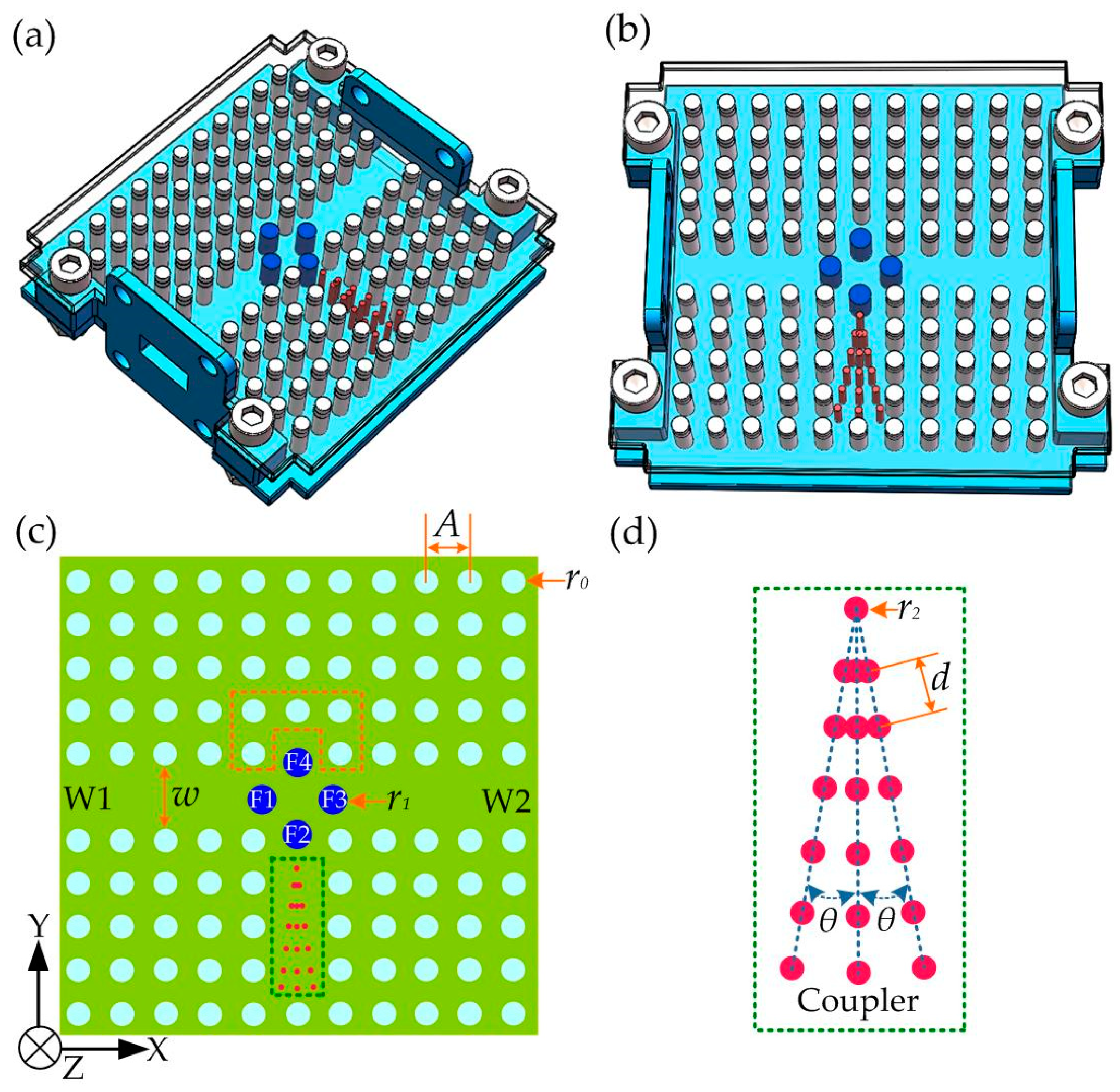
As shown in Figure 1a, the designed PCs isolator includes two SLPCs (white), four ferrite posts (blue) and a built-in fan-shaped coupler (red). The top view of the isolator is described in Figure 1b. In Figure 1c, the SLPCs are formed by Al2O3 ceramic rods arrays (white), while the radius and the relative dielectric constant of the rods are r0 and 9.2. The lattice constant of SLPCs is represented as A. The distance between the upper and lower arrays is marked by the width w. A list of rods at the central of the lower array is removed to form a T-shaped PCW, whose two collinear arms are expressed as W1 and W2.
The third arm of the PCW is closed, in which a fan-shaped PC array structure is introduced, which is also formed by Al2O3 ceramic rods with radius r2. The area of the fan-shaped PCs is determined by the angle θ and the distance d of the two rods, as shown in Figure 1d. The fan-shaped coupler is exactly located in the middle of the lower arm of the T-shaped PCW. The total length of the fan-shaped coupler is 6 mm with d = 0.5A, where A is assumed 4 mm long. At the center of the PCW, four ferrite posts (blue) with the radius r1 and relative dielectric constant 13.5 are introduced, which are marked F1, F2, F3 and F4.
In our scheme above, two standard WR34 flange interfaces are designed according to the two arms of the PCW, which are the input and output ports of the isolator. The size of the flange interfaces is w h, where w is 8.64 mm and h is 4.32 mm. The structure has a compact size about of 46.6 41.6 4.32 mm3 owed to the ingenious design of the built-in fan-shaped coupler. There is no need to use the WR34 matched load alone, which has a comparable size. In our current design analysis, we leave the fan-shape area as it is to obtain the s-parameters and test its bandwidth. For practical fabricated isolators, the bottom of the fan-shape area can be opened with a third connector window, to which a 50 Ohm load can be conveniently attached. In this aspect, our design is no different from existing isolator designs. In addition, some literature has employed wedge type styrofoam to absorb energy inside the device [24].
2.2. PBG of the SLPCs
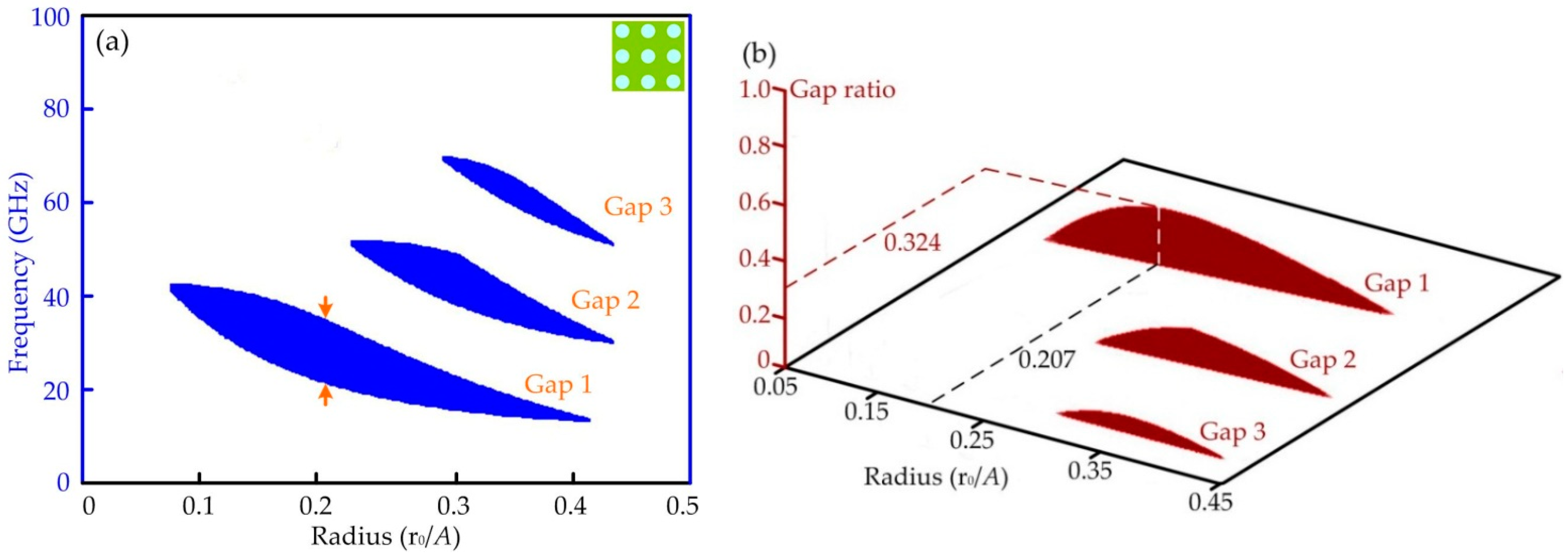
The PBG of the SLPCs determines the frequency of the electromagnetic waves which can transmit through the SLPCs or be reflected by them. When the lattice constant A is 4 mm, expressed as the distance of the two adjacent Al2O3 rods, the PBGs of the SLPCs mentioned above are calculated by PWEM.
In Figure 2a, there are three band gaps for TE modes with the different radius of the Al2O3 rods. The corresponding gaps’ radios with increasing rods’ radius are shown in Figure 2b. The interested frequency region is coincidentally contained in the first PBG (Gap 1). When the radius of Al2O3 rods r0 takes 0.207A, the optimal gap ratio achieves 32.7%, and the corresponding frequency range of the PBG is from 23.36 to 32.45 GHz. Theoretically, the SLPCs forbid the transmission of signals within the frequency range and reflect them back. If certain transmission line surrounded by the SLPCs, the electromagnetic waves with the frequencies in the PBG can transmit stably in the PCW just as mentioned above.
3. Photonic-Crystals Isolator
3.1. Operating Principle of Faraday Rotation Isolator
In the K waveband, if a ferrite post is magnetized in z-direction, its magneto-optical effect is usually described in terms of the tensor permeability [25]:
where and with , and . Here, and depend on material parameters. The external DC field is , which is reduced twofold compared with that in [23]. The symbol of the off-diagonal element is decided by the direction of external DC magnetic field and the strength of Faraday rotation effect is determined by the quality factor .
Isolators based on the Faraday rotation effect have been discussed in infrared, terahertz and optical waveband [26,27]. The principle of our designed isolator is similar to a T-shaped Faraday rotation circulator with one port shorted. Based on the Faraday rotation effect, the electromagnetic wave splits a pair of rotary degenerate modes, which it transmits into the magnetized ferrite post. The speeds of the two modes are different from each other. Thus, the composite wave of the two modes takes place a Faraday rotation angle when these deviate from each ferrite area. In this simulation, there is a pair of degenerate modes in the ferrite post such as Figure 3 in [28] with 0. When the ferrite posts are fully magnetized, the two modes are coupled, which leads to a Faraday rotation of the wave front in the area of ferrite posts. Here, a 45° rotation of electromagnetic wave can be realized with appropriate operating conditions through each ferrite post. The propagation direction of the electromagnetic waves is deflected in the ferrite area, which mainly attributed to the Faraday rotation effect.
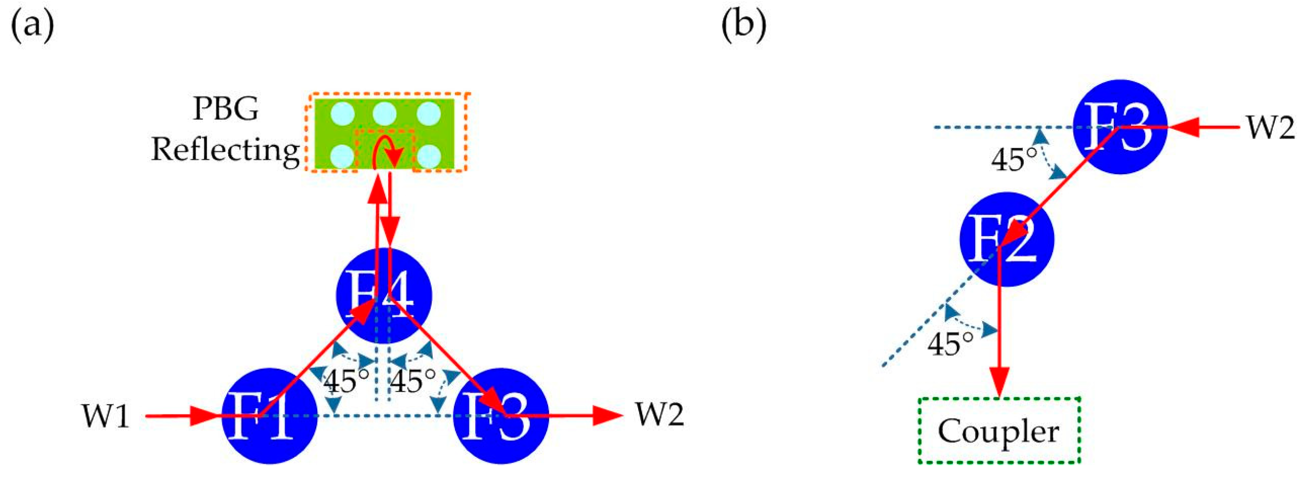
In Figure 3, the operating principle of the designed PC isolator is introduced by describing two transmission paths. The electromagnetic wave incoming from W1 takes place a 90° rotation by the cooperation of the ferrite posts F1 and F4 and is totally reflected by the cavity. The reflecting cavity consists of the ferrite post F4 and the five Al2O3 rods in the orange dotted box as shown in Figure 1c. Then, the electromagnetic wave rotates with an angle of 90° again when it transmits through the ferrite posts F4 and F3 sequentially. Finally, the signal exactly travels to W2 as shown in Figure 3a. It can be seen that the electromagnetic wave transmission along a straight line is realized by bending twice of 90° with the three ferrite posts and the aid of the reflecting cavity.
Similarly, Figure 3b illustrates the path of electromagnetic waves incoming from W2. The electromagnetic wave is firstly rotated by an angle of 45° through the ferrite post F3 and then another angle of 45° through the ferrite post F2. Then a 90° bend of electromagnetic wave is obtained by the cooperation of the two ferrite posts. Finally, the electromagnetic wave travels into the fan-shaped coupler shown in Figure 1d and is almost all confined in it, thus the W1 is isolating. Here, the built-in fan-shaped coupler works similar to a matched load, whose PBG is different from that of the SLPCs, so the input electromagnetic wave can diffuse in the coupler but is confined in the third arm of the T-shaped PCW. In microwave circuits, the modified port is usually deemed to have ‘short-circuited’. Furthermore, we can adjust the angle θ mentioned above in order to achieve the superior isolation for W1 of the isolator.
3.2. Numerical Simulation of the PCs Isolator
In this section, the function and transmission characteristics of the PCs isolator are numerically simulated by the software COMSOL Multiphysics like [10], based on the following equation:
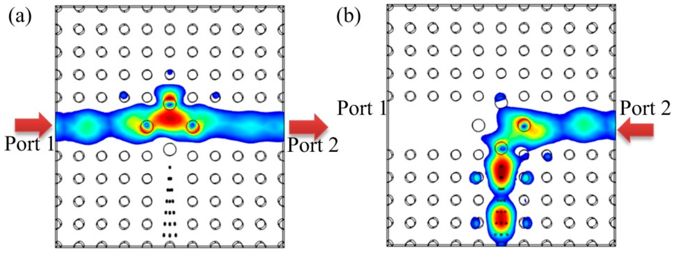
where ε is the relative dielectric constant of the materials, ω is the frequency of incident signal, c is the speed of the light and is the electric field intensity. The parameters of the designed PCs isolator are , , , , , , w and h . At 26 GHz, the power distribution of the signal in the PCs isolator is shown in Figure 4.
As shown in Figure 4a, the signal incoming from Port 1 is transmitted stably to Port 2. Nonreciprocally, the signal incoming from Port 2 totally travels into the fan-shaped coupler, thus Port 1 is isolated, as in Figure 4b. Consequently, it perfectly realizes the function of the PC isolator, and its external properties are also numerically calculated as shown in Figure 5.
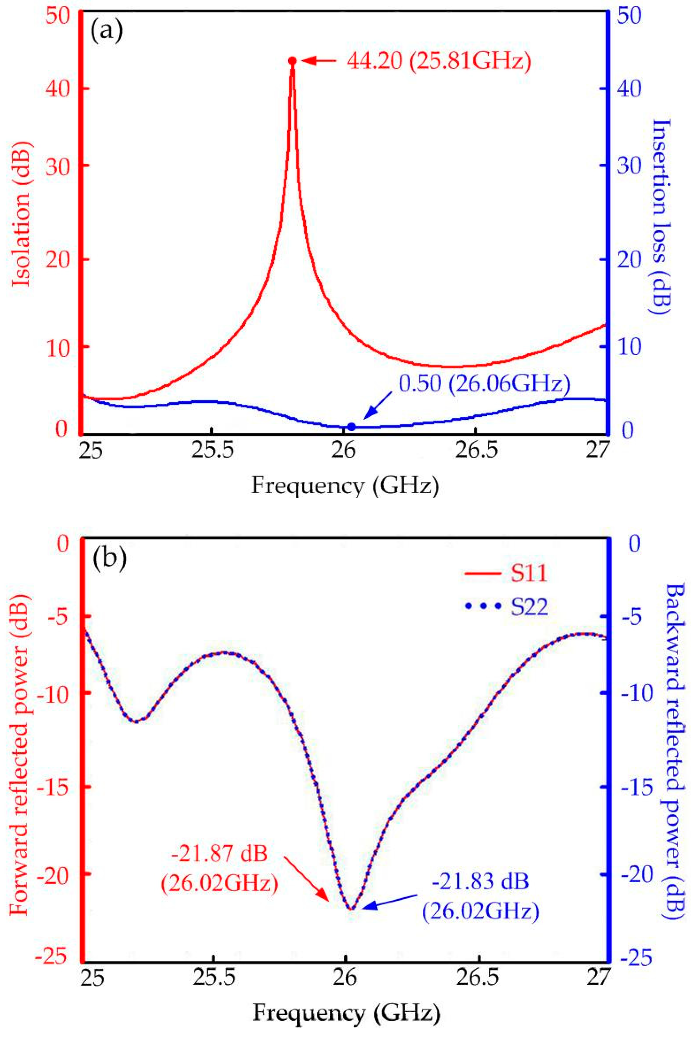
In Figure 5a, the numerical results suggest that the optimal isolation of the PCs isolator is 44.20 dB at 25.81 GHz, and the isolation remains above 15 dB within the range of 25.66 to 25.95 GHz. In addition, the insertion loss is low to 0.50 dB at 26.06 GHz with the transmission efficiency of above 50% (3 dB) over a wide frequency range from 25.03 to 26.92 GHz, revealing an excellent forward transmission characteristic of the proposed PCs isolator. The curves of the forward and backward reflected powers of the PCs isolator with frequency are basically coincident, as shown in Figure 5b. It means that the return losses of the two ports are almost the same, which are reflected by the symmetrical structure. The peaks of the S parameters S11 and S22 respectively are −21.87 dB and −21.83 dB at 26.02 GHz. The S parameters play important roles in describing the performance of the devices, which are the ratios between the powers of waves between these ports. In our design, the parameters S11 and S22 represent the ratio of the reflected power to the input power of the Port 1 and Port 2, respectively. The parameter S21 represents the insertion loss of the isolator, which is the logarithmic value of the ratio of the transmission power of the Port 2 from the input power of the Port 1. Moreover, the parameter S12 is used to measure the isolation performance of the isolator, which is described in detail in [10].
4. Conclusions
In conclusion, a new compact PC isolator based on the Faraday rotation effect is demonstrated numerically by inserting Ni–Zn gyromagnetic ferrite posts into a T-typed SLPCs defect structure. As the radius of SLPCs’ rods r0 takes 0.207A, the optimal gap ratio of 32.7% achieves an ultra-wideband level, and the corresponding frequency range of the PBG is from 23.36 to 32.45 GHz. The optimal forward transmission efficiency and reverse isolation of the isolator reach 0.50 dB and 44.20 dB, respectively. With the unique reflecting cavity and built-in fan-shaped coupler, the structure of the designed isolator is more compact for integration. Our designed PCs isolator with high isolation and low insertion loss shows potential applications in future 5G communication systems.
Author Contributions
Conceptualization, D.Z., W.H. and H.I.; methodology, Y.W.; software, Y.W. and B.X.; validation, Y.W. and B.X.; formal analysis, Y.W.; investigation, Y.W., D.Z. and H.I.; resources, D.Z., W.H. and H.I.; data curation, Y.W. and B.X.; writing—original draft preparation, Y.W.; writing—review and editing, D.Z. and H.I.; visualization, Y.W.; supervision, H.I.; project administration, Y.W.; funding acquisition, H.I. All authors have read and agreed to the published version of the manuscript.
Funding
H.I. thanks the support by the FDCT of Macau under Grant 0130/2019/A3 and by University of Macau under Grant MYRG2018-00088-IAPME.
Institutional Review Board Statement
Not applicable.
Informed Consent Statement
Not applicable.
Data Availability Statement
Not applicable.
Acknowledgments
The authors would like to acknowledge the Institute of Applied Physics and Materials Engineering of University of Macau and the College of Electronics and Information Technology of Shenzhen University.
Conflicts of Interest
The authors declare no conflict of interest.
References
- Vartanian, P.H.; Ayres, W.P.; Melchor, J.L. Broadband ferrite microwave isolator. IRE Trans. Microw. Theory Tech. 1956, 4, 8–13. [Google Scholar] [CrossRef]
- Shalaby, M.; Peccianti, M.; Ozturk, Y.; Morandotti, R. A magnetic non-reciprocal isolator for broadband terahertz operation. Nat. Commun. 2013, 4, 1–7. [Google Scholar] [CrossRef]
- Cheng, Y.J.; Huang, Q.D.; Wang, Y.R. Narrowband substrate integrated waveguide isolators. IEEE Microw. Wirel. Compon. Lett. 2014, 24, 698–700. [Google Scholar] [CrossRef]
- Ohm, E.A. A broad-band microwave circulator. IRE Trans. Microw. Theory Tech. 1956, 4, 210–217. [Google Scholar] [CrossRef]
- Zhang, D.G.; Lin, W.G. A new design method of H-plane waveguide circulator. Int. J. Infrared Millim. Waves 1988, 9, 173–177. [Google Scholar]
- Yung, E.K.N.; Zhang, D.G.; Wong, R.S.K. A novel waveguide Y-junction circulator with a ferrite sphere for millimeter waves. IEEE Trans. Microw. Theory Tech. 1996, 44, 454–456. [Google Scholar] [CrossRef]
- Shoji, Y.; Mizumoto, T. Silicon Waveguide Optical Isolator with Directly Bonded Magneto-Optical Garnet. Appl. Sci. 2019, 9, 609. [Google Scholar] [CrossRef] [Green Version]
- Aroua, W.; AbdelMalek, F.; Haxha, S. Mode converter optical isolator based on dual negative refraction photonic crystal. IEEE J. Quantum Electron. 2014, 50, 633–638. [Google Scholar] [CrossRef] [Green Version]
- Dmitriev, V.; Kawakatsu, M.N.; Souza, F.J.M. Compact three-port optical two-dimensional photonic crystal-based circulator of W-format. Opt. Lett. 2012, 37, 3192–3194. [Google Scholar] [CrossRef]
- Wang, Y.; Zhang, D.G.; Xu, B.G.; Dong, Z.; Zeng, X.K.; Pei, J.H.; Xu, S.X.; Xue, Q. Four ports double Y-shaped ultra-wideband magneto-photonic crystals circulator for 5G communication system. IEEE Access 2019, 7, 120463–120474. [Google Scholar] [CrossRef]
- Labilloy, D.; Benisty, H.; Weisbuch, C.; Krauss, T.F. Demonstration of cavity mode between two-dimensional photonic-crystal mirrors. Electron. Lett. 1997, 33, 1978–1980. [Google Scholar] [CrossRef]
- Němec, H.; Kužel, P.; Duvillaret, L.; Pashkin, A.; Dressel, M.; Sebastian, M.T. Highly tunable photonic crystal filter for the terahertz range. Opt. Lett. 2005, 30, 549–551. [Google Scholar] [CrossRef]
- Jiang, Y.; Jiang, W.; Gu, L.; Chen, X.; Chen, R.T. 80-micron interaction length silicon photonic crystal waveguide modulator. Appl. Phys. Lett. 2005, 87, 221105. [Google Scholar] [CrossRef] [Green Version]
- Song, B.S.; Noda, S.; Asano, T. Photonic devices based on in-plane hetero photonic crystals. Science 2003, 300, 1537–1538. [Google Scholar] [CrossRef] [PubMed]
- Liu, Q.; Ouyang, Z.; Wu, C.J.; Liu, C.P.; Wang, J.C. All-optical half adder based on cross structures in two-dimensional photonic crystals. Opt. Express 2008, 16, 18992–19000. [Google Scholar] [CrossRef]
- Bai, J.; Wang, J.; Jiang, J.; Chen, X.; Li, H.; Qiu, Y.; Qiang, Z. Photonic NOT and NOR gates based on a single compact photonic crystal ring resonator. Appl. Opt. 2009, 48, 6923–6927. [Google Scholar] [CrossRef]
- Iadanza, S.; Devarapu, C.; Liles, A.; Sheehan, R. Hybrid External Cavity Laser with an Amorphous Silicon-Based Photonic Crystal Cavity Mirror. Appl. Sci. 2020, 10, 240. [Google Scholar] [CrossRef] [Green Version]
- John, S. Strong localization of photons in certain disordered dielectric super-lattices. Phys. Rev. Lett. 1987, 58, 2486–2489. [Google Scholar] [CrossRef] [PubMed] [Green Version]
- Krauss, T.F.; Richard, M.D.L.R. Photonic crystals in the optical regime—past, present and future. Progress Quantum Electron. 1999, 23, 51–96. [Google Scholar] [CrossRef]
- Kato, H.; Matsushita, T.; Takayama, A.; Egawa, M.; Nishimura, K.; Inoue, M. Properties of one-dimensional magnetophotonic crystals for use in optical isolator devices. IEEE Trans. Magn. 2002, 28, 3246–3248. [Google Scholar] [CrossRef]
- Fang, K.; Yu, Z.; Liu, V.; Fan, S. Ultracompact nonreciprocal optical isolator based on guided resonance in a magneto-optical photonic crystal slab. Opt. Lett. 2011, 36, 4254–4256. [Google Scholar] [CrossRef] [Green Version]
- Wang, Z.; Chong, Y.; Joannopoulos, J.D.; Soljacic, M. Observation of unidirectional backscattering- immune topological electromagnetic states. Naure 2009, 461, 772–775. [Google Scholar] [CrossRef] [Green Version]
- Wang, Y.; Xu, B.G.; Zhang, D.G.; Xu, S.X.; Dong, Z.; Zeng, X.K.; Lu, X.W.; Pei, J.H. Magneto-optical isolator based on ultra-wideband photonic crystals waveguide for 5G communication system. Crystals 2019, 9, 570. [Google Scholar] [CrossRef] [Green Version]
- Stander, T.; Walt, P.W.V.; Meyer, P.; Steyn, W. A comparison of simple low power wedge type X-band waveguide absorbing load implementations. In Proceedings of the AFRICON 2007, Windhoek, Namibia, 26–28 September 2007. [Google Scholar]
- Višňovský, Š. Magnetooptics in Cylindrical Structures. Appl. Sci. 2018, 8, 2547. [Google Scholar] [CrossRef] [Green Version]
- Iwamura, H.; Hayashi, S.; Iwasaki, H. A compact optical isolator using a Y3Fe5O12 crystal for near infra-red radiation. Opt. Quant. Electron. 1978, 10, 393–398. [Google Scholar] [CrossRef]
- Steel, M.J.; Levy, M.; Osgood, R.M. High transmission enhanced Faraday rotation in one-dimensional photonic crystals with defects. IEEE Photon. Technol. Lett. 2000, 12, 1171–1173. [Google Scholar] [CrossRef]
- Wang, Y.; Zhang, D.G.; Xu, S.X.; Ouyang, Z.B.; Li, J.Z. Low-loss Y-junction two-dimensional magneto-photonic crystals circulator using a ferrite cylinder. Opt. Commum. 2016, 369, 1–6. [Google Scholar] [CrossRef]
Figure 1.
(a) The schematic diagram of the PC isolator; (b) the top view of the isolator; (c) the plan view of the isolator; (d) the detailed view of the coupler.
Figure 1.
(a) The schematic diagram of the PC isolator; (b) the top view of the isolator; (c) the plan view of the isolator; (d) the detailed view of the coupler.

Figure 2.
(a) The TE band gaps of the SLPCs with the Al2O3 rods’ radius; (b) the gaps’ ratios with the radius of the Al2O3 rods.
Figure 2.
(a) The TE band gaps of the SLPCs with the Al2O3 rods’ radius; (b) the gaps’ ratios with the radius of the Al2O3 rods.

Figure 3.
(a) The path of electromagnetic wave incoming from W1; (b) the path of electromagnetic wave incoming from W2.
Figure 3.
(a) The path of electromagnetic wave incoming from W1; (b) the path of electromagnetic wave incoming from W2.

Figure 4.
The power distribution in the PCs isolator at 26 GHz. (a) signal incoming from Port 1 is transmitted stably to Port 2. (b) signal incoming from Port 2 totally travels into the fan-shaped coupler.
Figure 4.
The power distribution in the PCs isolator at 26 GHz. (a) signal incoming from Port 1 is transmitted stably to Port 2. (b) signal incoming from Port 2 totally travels into the fan-shaped coupler.

Figure 5.
(a) The curves of isolation and insertion loss of the PC isolator with frequency; (b) the curves of the forward and backward reflected powers of the PC isolator with frequency.
Figure 5.
(a) The curves of isolation and insertion loss of the PC isolator with frequency; (b) the curves of the forward and backward reflected powers of the PC isolator with frequency.

Publisher’s Note: MDPI stays neutral with regard to jurisdictional claims in published maps and institutional affiliations. |
© 2021 by the authors. Licensee MDPI, Basel, Switzerland. This article is an open access article distributed under the terms and conditions of the Creative Commons Attribution (CC BY) license (https://creativecommons.org/licenses/by/4.0/).
Share and Cite
MDPI and ACS Style
Wang, Y.; Xu, B.; Zhang, D.; He, W.; Ian, H. Compact Photonic-Crystals Based Isolator Using Ni–Zn Gyromagnetic Ferrite Posts. Appl. Sci. 2021, 11, 6177. https://0-doi-org.brum.beds.ac.uk/10.3390/app11136177
AMA Style
Wang Y, Xu B, Zhang D, He W, Ian H. Compact Photonic-Crystals Based Isolator Using Ni–Zn Gyromagnetic Ferrite Posts. Applied Sciences. 2021; 11(13):6177. https://0-doi-org.brum.beds.ac.uk/10.3390/app11136177
Chicago/Turabian StyleWang, Yong, Biaogang Xu, Dengguo Zhang, Wenlong He, and Hou Ian. 2021. "Compact Photonic-Crystals Based Isolator Using Ni–Zn Gyromagnetic Ferrite Posts" Applied Sciences 11, no. 13: 6177. https://0-doi-org.brum.beds.ac.uk/10.3390/app11136177
Note that from the first issue of 2016, this journal uses article numbers instead of page numbers. See further details here.