
On the Improvement of ROS-Based Control for Teleoperated Yaskawa Robots


1
Capacites SAS, LS2N-UMR 6004, 2 Av. Pr. Jean Rouxel, 44475 Carquefou, France
2
GMP Department, University of Nantes, IUT Nantes, LS2N-UMR 6004, 2 Av. Pr. Jean Rouxel, 44475 Carquefou, France
*
Author to whom correspondence should be addressed.
Appl. Sci. 2021, 11(16), 7190; https://0-doi-org.brum.beds.ac.uk/10.3390/app11167190
Submission received: 20 May 2021
/
Revised: 26 July 2021
/
Accepted: 27 July 2021
/
Published: 4 August 2021
(This article belongs to the Special Issue Control and Motion Planning in Industrial Applications)
Abstract
:This paper deals with Yaskawa robots controlling the Robot Operating System (ROS) for teleoperation tasks. The integration of an open-source ROS interface based on standard Motoman packages into control loop leads to large trajectory tracking errors and latency, which are unsuitable for robotic teleoperation. An improved version of the standard ROS-based control is proposed by adding a new velocity control mode into the standard Motoman ROS driver. These two approaches are compared in terms of response time and tracking delay. Investigations applied on the Yaskawa GP8 robot while using the proposed improved ROS-based control confirmed trajectory tracking and latency improvements, which can achieve 43% with respect to standard control.
1. Introduction
Robotic teleoperation is used in a wide variety of areas such as medicine [1], under-water exploration [2], space activities [3], and nuclear operation [4] to perform tasks in environments that are hazardous [5] or inaccessible to humans. Teleoperation systems involve manipulators enabling man to act mechanically and remotely via sensory feedback, mostly vision and effort. It typically requires a high level of operator expertise and may imposes a considerable cognitive load [6]. Probably the most important issue for tele-robotics is the time-delay issue [7] as it includes human in the loop. Teleoperation latency is the subject of paper [8], as it has a substantial impact on the surgical robots performance. The authors of this work present an improved teleoperation system that includes supervisory control, haptic feedback and motion scaling with augmented reality. This improvement results in signal latency reduction and superior performance compared to the conventional telesurgery system. A survey on bilateral teleoperation is presented in [9]. A bilateral teleoperation system consists of operating a machine at a distance while exchanging the action and reaction information between the master and the slave bidirectionaly in real time via a communication channel. A bilateral teleoperation system with time-varying time-delay was studied in [10]. An observer-based control was proposed while considering the different time-delay in the forward and backward paths. By applying this control law, synchronization of the teleoperation system at both sides are achieved. However, teleoperation systems frequently experience significant time delays in communication between the local and remote sites, which necessarily limit the user performance as shown in [11,12]. Furthermore, the combination of system control with even small time delays creates stability problems [13], which has led to alternative control approaches. Robotic teleoperation is proposed in [14] for imitation learning data collection. Such method represents stochastic artificial intelligence approaches and is used for complex manipulation tasks. Alternative deterministic artificial intelligence approaches are proposed in [15] to assert deterministic self-awareness statements based on either the physics of the underlying problem or system identification to establish governing differential equations. Significant time delay between the command specification and its execution may occur in some teleoperated robotic systems because of the distance separating the robot and control site [16], which is the case in [17]. Researchers of the latter work used CAD-based models and computer graphics overlays of the camera views to check if the robot path is collision-free. It was shown that such technique is not practical for guaranteeing collision-free motion for the entire body of the robot arm manipulator because of time delays. The research work in [18] concludes that latencies between 400 ms and 500 ms may be acceptable for precise teleoperation tasks, such as telesurgery. Beyond 600 ms, latencies are difficult to deal with and are acceptable only for low risk and simple procedures. It is confirmed in [19,20] that the inspection of robot real-time response is necessary for teleoperated robotic applications. In fact, as we are interested in robotic teleoperation, one contribution of this paper is the identification of real-time performance degradation sources in order to identify and apply the required developments and improvements of robot control.
Workspace limitations make the robot control and remote piloting difficult. Simulation tools are useful to predict robot behavior in teleoperation to verify the interactions absence between the robot links and its environment. ROS-based robot simulation has developed relative maturity over the past two decades thanks to ROS benefits. ROS is an open source operating system designed for robots, which provides features such as hardware abstraction, low-level device control, packages for common features, a communication framework, and a variety of libraries and tools to help build robotic applications. To model systems with realistic physics, improved simulation tools are needed. The gazebo tool [21] consists of a physics engine, high quality graphics, and programmatic and graphical interfaces. It can simulate any custom designed physical model described in XML-based SDF or URDF file format [22]. Several famous robots have been simulated in the ROS and Gazebo platforms, such as PR2 [23] and TurtleBot [24]. Functionalities provided by ROS and Gazebo make them suitable to predict the robot auto-collision and its intersection with the environment [25]. Stop criteria use (prohibited areas, collisions, singularities, etc.) allows having a realistic rendering of the robot capabilities in simulation, while carrying out teleoperation tasks [26]. Therefore, ROS-based control coupled with Gazebo simulation is proposed in this paper to ensure the safety of teleoperation task.
Controlling industrial robots from an external computer using ROS differs greatly from classical robot programming methods provided by industrial robot sellers. As such, the commercial interfaces available for use with ROS often rely on the user writing custom programs for each new application. A first contribution of this paper is the evaluation of the open-source control interface based on standard Motoman driver package [27] created with the cooperation of Yaskawa Motoman, in order to check its effectiveness for teleoperation tasks. It should be noted that Yaskawa robots are used in different fields such as surgery [28], pick and place [29], welding [30], etc. Recently, NASA selected its Motoman SIA50 robots for teleoperation demonstration [31]. It successfully confirmed the ability to robotically transfer oxidizer to a satellite valve in flight-like conditions.
The standard Motoman driver package uses ROS-Industrial basic nodes and interfaces them with Yaskawa Motoman robot controllers. The research work in [32] proposesda setup of the Motoman SDA_10 dual-arm robot with ROS-Industrial for industrial applications. Real-time response of robotic system and its communication latency analysis leads to better controlling, as confirmed for ROS-controlled KUKA robots in [33]. This analysis highlights the required extra developments to be carried out. The resulting performance degradation sources are identified: A second contribution of this paper deals with the proposition of an improved version of Motoman ROS-based control suitable for teleoperation tasks. The modifications of the standard Motoman ROS package is proposed to compensate the depicted delays to deal with teleoperation. It manifests in the addition of a new velocity control mode into the Motoman ROS driver. The experimental evaluation of the improved ROS-based control, applied on a 6 Degrees-of-Freedom (DoFs) Yaskawa GP8 robot, teleoperated by a 3DConnexion Space-Mouse Pro device, confirms an improvement on the robot teleoperation performance, in terms of latency and trajectory tracking, which can achieve 43% with respect to the standard control.
This paper is organized as follows: Section 2 presents the kinematic equations of motion of a serial robot required to establish the control laws for teleoperation. Section 3 introduces the design of ROS-based control while integrating Motoman ROS package. Then, the effectiveness of the standard control method for robot manipulators teleoperation is discussed in detail in Section 4. Finally, the improvement of the standard ROS-based control method for Yaskawa manipulators is proposed in Section 5. The effectiveness of the proposed control method is then studied to check its performance regarding to robot teleoperation performance compared to the standard one.
2. Kinematic Modeling for ROS-Based Teleoperation
The system studied in this paper is a serial m-DoFs robot. It is composed of a sequence of n links. The notations of Khalil and Dombre are used [34] to describe the structure with only revolute joints. We assign a frame attached to the ith link, . The -axis is coincident with the ith joint axis. The is along the common normal between and . The -axis is formed by the right-hand rule to complete the coordinate system.
The transformation matrix from to is expressed as a function of the following geometric parameters:
- : the angle between and about .
- : the distance between and along .
- : the angle between and about .
- : the distance between ans along .
The variable of ith joint, defining the relative orientation between th and ith links is expressed by:
where is a constant offset and q is the ith joint position. The homogeneous transformation matrix , defining relative to is expressed as follows:
The direct kinematic model of a robot manipulator expresses the end-effector (EE) velocity as a function of the joint velocities .
where is the Jacobian matrix. It also appears in the direct differential model, which provides the differential EE displacement as a function of the joint differential variation :
The Jacobian matrix is derived from the direct geometric matrix (DGM), where the EE pose is expressed as . It is obtained by the differentiation of the DGM using partial derivative , such that:
is the (k,j) element of . The inverse kinematic model is then:
3. ROS-Based Robot Control for Teleoperated Task
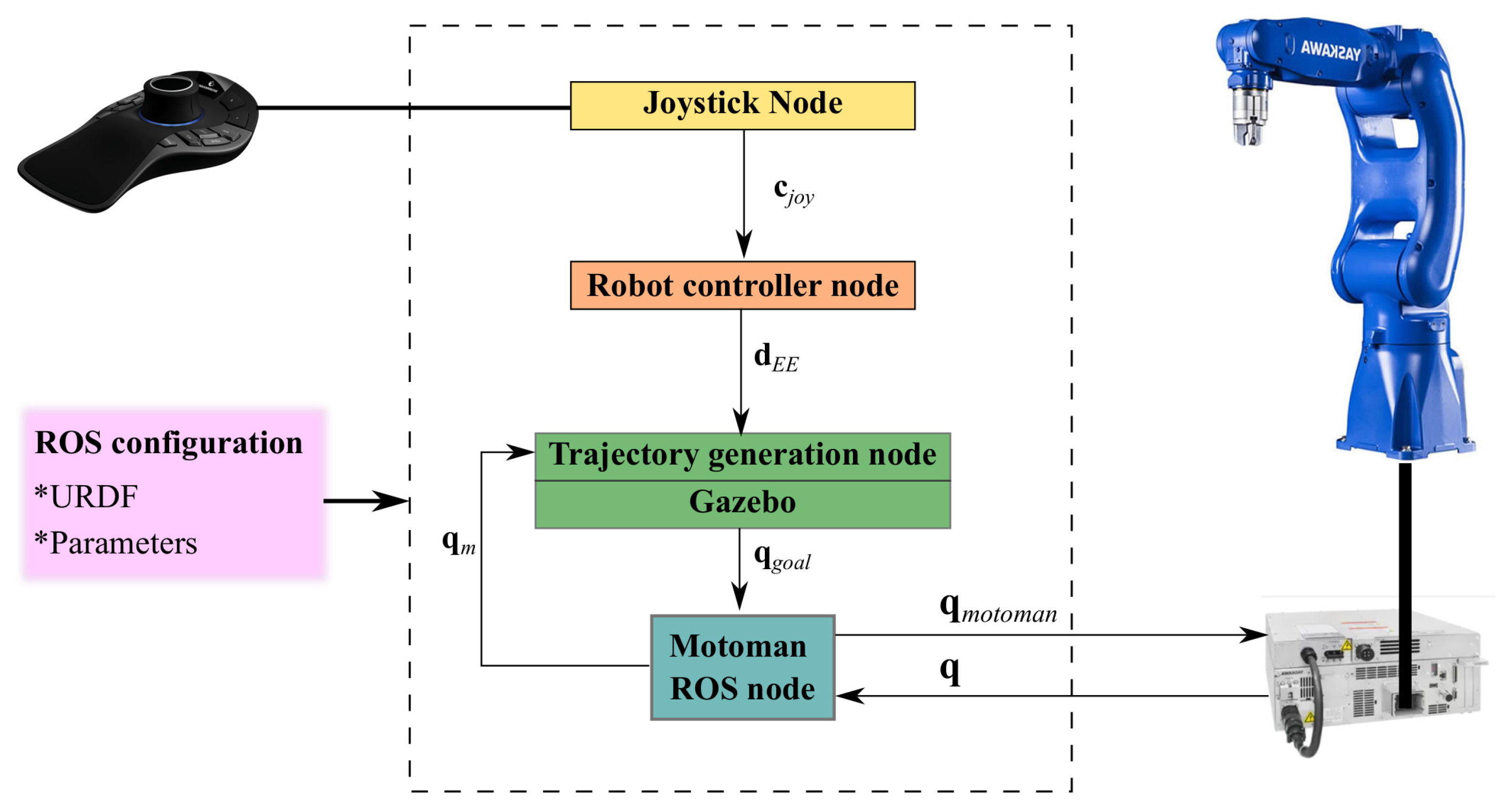
The studied system is mainly composed by a m-DoFs Yaskawa robot teleoperated by a joystick. To manipulate this system, a ROS-based control scheme is used for teleoperation tasks. This control method is described in Figure 1. It consists of:
- The “Joystick node” allows reading the peripheral components as well as the buttons state. This node corresponds to the “joystick_drivers” metapackage of ROS, which is used for interfacing common joysticks and human input devices with ROS. It provides “joy”, “Spacenav_node”, “ps3joy” and “wiimote” packages, which are compatible with generic Linux joystick, 3Dconnexion SpaceNavigator 6-DOF joystick, Playstation 3 SIXAXIS or DUAL SHOCK 3 joystick and Nintendo Wiimote, respectively. The piloting mode is supposed to be a mixture between the articular and the Cartesian modes, so that both modes are enabled simultaneously. This mixture is defined by the joystick instruction vector . m is the degree of freedom of the joystick. , where is the articular displacement instruction, is the Cartesian displacement instruction and . In other words, k axis of the joystick are set to give Cartesian instructions and j axis of the joystick are set to give articular instructions. Please note that the Cartesian instruction can correspond either to a conventional Cartesian motion or to a complex user-defined motion.
- The “Robot controller node” contains the teleoperation piloting modes programmed in the simulator. This node is used to transform the mouse articular or/and Cartesian motion instructions into the EE setpoint . When the robot is supposed to perform only articular and conventional Cartesian task, is expressed as:where and are constant sensitivity parameters, which are set with respect to the operator expertise and manipulation.
- The “Trajectory generation node”/“Gazebo node” is the simulation part of the robot under ROS. It is responsible for generating the trajectory according to the behavior criteria of the robot (maximum speeds and accelerations, joint limits, etc.). It will generate a succession of joint positions of the robot over time calculated by the Robot Controller node. When the simulator depicts a prohibited motion, no joint goal displacement is sent to “Motoman ROS node”.
- The “Motoman ROS node” is the interface between simulation and reality. It is responsible for communicating motion tasks to the robot and retrieving information on its current positions . This feedback is then transmitted, as , to the Gazebo node to perform the servo-control. The ROS and ROS-Industrial Motoman community provides a set of nodes and mechanisms to facilitate the communication with the robot, namely the ROS Motoman driver [27]. The Motoman driver controller interface was created with the cooperation of Yaskawa Motoman, to provide a more high-performance interface for controlling Motoman robots. The software works on all FS100, DX100, DX200, YRC1000 and YRC1000micro robot controllers.
For each communication between the different nodes, we consider that there is an information transmission delay. This latter has to be measured in order to have an idea of the system performance. It should be noted that this performance depends on numerous factors such as the simulation computer configuration and processor. A possible source of these delays variation can be the transmission network, which itself can vary. Due to the fact that the robot is connected to other elements through a communication channel, latency and data loss caused by the communication network degrade the system stability and performance.
4. Evaluation of Standard Motoman ROS-Based Control for Teleoperation Tasks
In this section, the open-source control interface based on standard Motoman driver package [27], created with the cooperation of Yaskawa Motoman, is experimentally analyzed in order to check its effectiveness for teleoperation tasks of Yaskawa manipulators. Thanks to ROS, it is possible to tag precisely the times when data is sent and received on all nodes. Response time and tracking delay generated by the standard Motoman ROS-based control are investigated.
The evaluation of standard Motoman ROS-based control for teleoperation tasks is performed with an Intel Core i7-6700HQ processor computer. The motion task is done using a 3DConnexion Space-Mouse Pro device, which requires the implementation of “Spacenav_node” from “joystick_drivers” metapackage of ROS. The melodic version of ROS is used. For performance tests, we will perform three forward and backward articular motions of only the first axis of the 6 Degrees-of-Freedom (DoFs) Yaskawa GP8 robot, with a YRC1000 controller. The interface between the simulation and real robot is based on the Motoman ROS driver, which allows the interfacing between ROS-Industrial nodes with Yaskawa Motoman robot controllers.
Figure 2 shows the GP8 first axis articular displacement issued from the different nodes. The blue (green, red, respectvively) line presents the SpaceMouse motion instructions (articular displacement orders calculated by the trajectory generation node, measured robot articular position , respectively). Forward (backward, respectively) motions are red-framed (white-framed, respectively).
Table 1 summarizes the average of measured delay times of each phase. The measured latency between and is the image of the total latency. This latency is a decomposition of simulation latency, between and , and Motoman node latency, between and .
Experimental data shows that the total latency average while integrating the standard ROS-based control is equal to 0.780 s (>0.6 s), which is not acceptable for precise teleoperation tasks [18]. The simulation part has an average latency of 0.232 s, which corresponds to 29.74% of the total latency. The execution of Motoman driver node by sending and receiving has large delays, whose average is equal to 0.548 s. This corresponds to 70.26% of the total latency average. In addition to these delays, the robot motion presents regular stopping phases, while sending continuous motion task. Performance degradation of teleoperated robot is supposed to be related to software development.
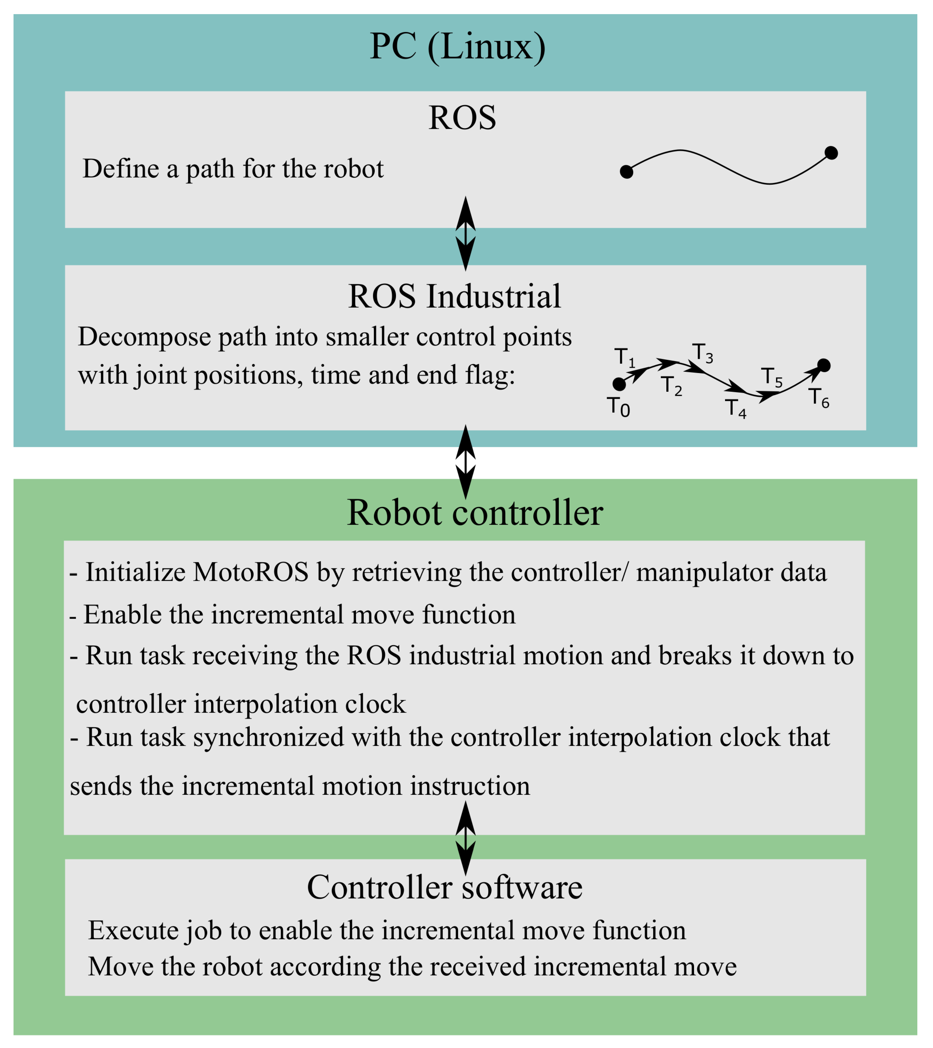
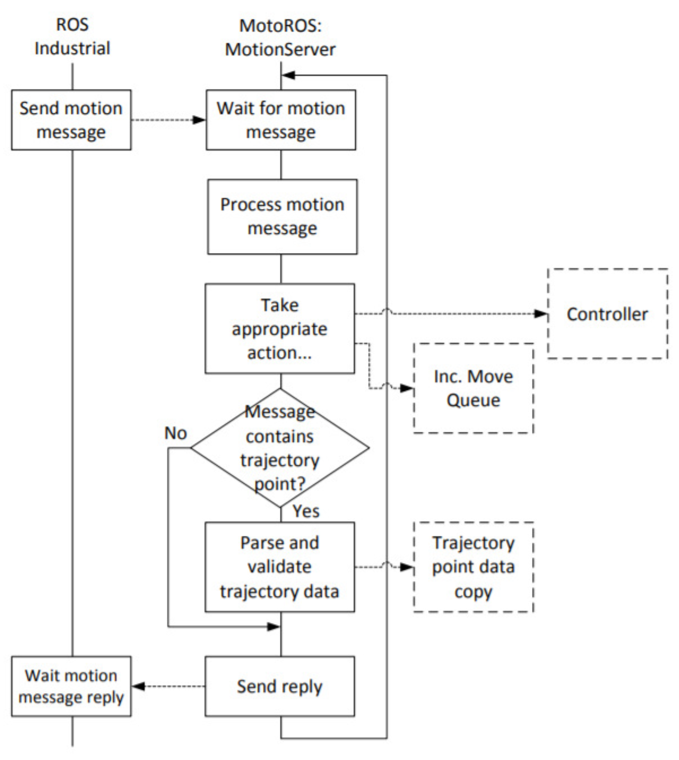
Figure 3 presents the Motoman ROS node architecture provided by Yaskawa Motoman documentation [35]. This node is based on the principle of two-point trajectories. Each trajectory is discretized by the Motoman ROS node and then sent to the robot controller. The MotoRos code then takes care of applying this interpolation between the different trajectory waypoints.
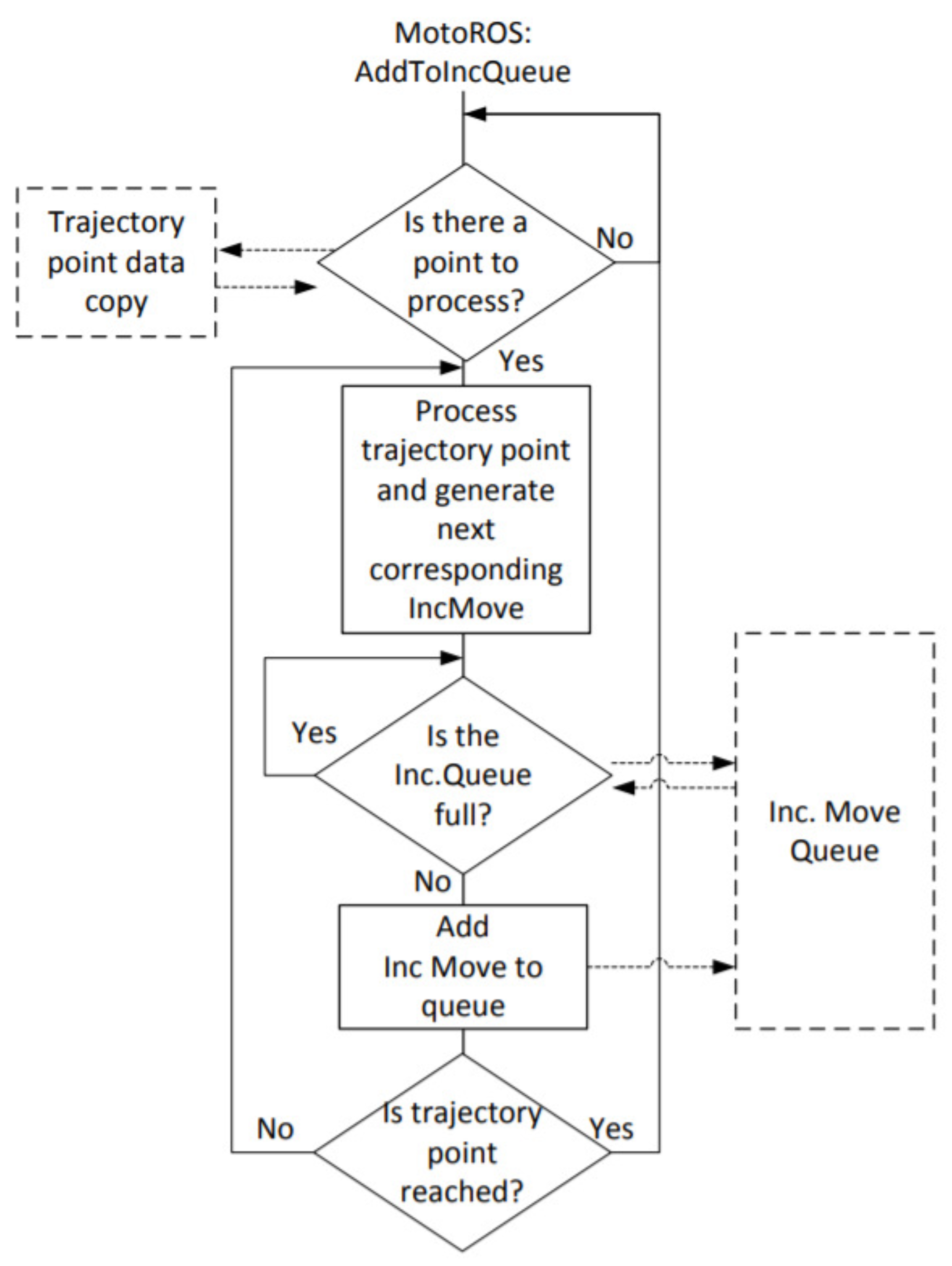
The diagrams of Figure 4 and Figure 5 from MotoRos documentation [35], describe the Motoman ROS node overall behavior. The ROS node is designed to send trajectories to the robot. Each path is made up of a waypoint sets, which are then packaged into a message sent to MotoROS. The robot is then responsible for making a position control to follow this trajectory. The latter is then executed in its entirety before being able to execute a new one. Each trajectory is calculated to have a zero start and end speed. Contrary to what the previous diagrams may suggest, the robot does not actually follow the trajectory imposed by the ROS node. It is more likely that, at the end of each trajectory, the interpolation system captures the current target position. Then, it calculates the trajectory with the acceleration and deceleration ramps. The transmission latency can be explained by the calculation delay. The calculated trajectory is then sent to the robot and a new trajectory is executed. This operation principle explains robot stops levels, seen in Figure 2, which are not suitable for teleoperation.
To remedy both problems, which appear to be more significant on the Motoman node, and to make it suitable to teleoperation tasks, development modification in the standard Motoman node will be proposed as a solution in Section 5.
5. Improved ROS-Based Control for Teleoperated Yaskawa Robots
As one can see, the standard Motoman node architecture is not suitable for teleoperation. To obtain an adequate operating mode, it is necessary to make modifications on the control method. This work is concerned with a method that can improve the performance of ROS-based robot control system. This method consists of the replacement of position control by velocity control. Therefore, the Motoman ROS node will be based on the kinematic model presented by Equation (6). Here, the motion direction and velocity are first determined and then converted into articular velocities. The improved system architecture becomes as mentioned in Figure 6.
Here, the generated EE setpoint becomes a velocity setpoint and is expressed as follows: It becomes:
The unit vector of presents the motion direction on the different robot axis. Its norm corresponds to the velocity amplitude. It should be noted that Gazebo display is disabled in order to enhance simulation latency. In this case, Gazebo functionalities and trajectory stop conditions stay active.
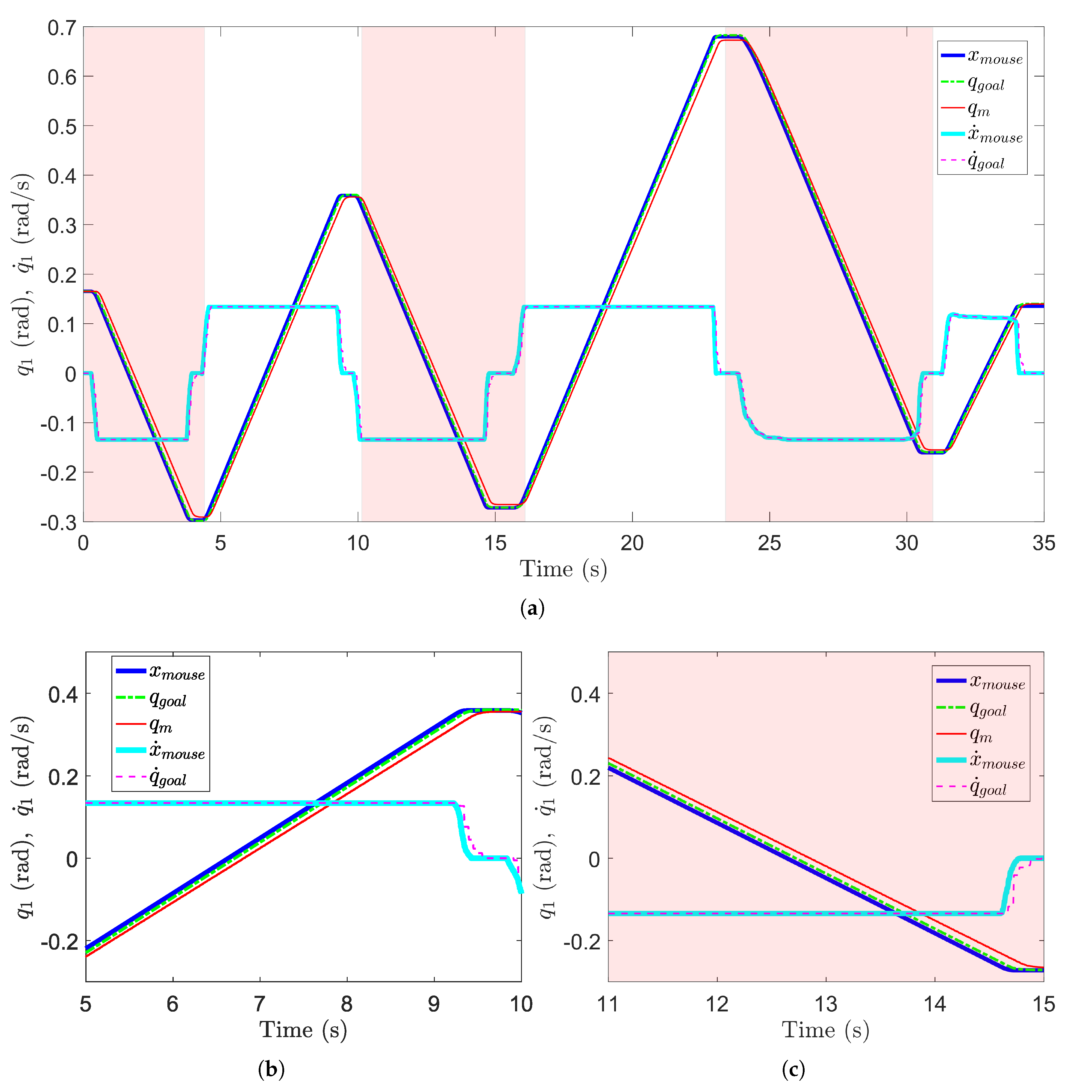
Performance tests, while applying the proposed modification, are performed by making three backward and forward articular motions of only the first axis of a GP8 Yaskawa robot teleoperated by a 3DConnexion Space-Mouse Pro device, described in Section 4. The resulting first axis articular displacement is presented in Figure 7. The average value of measured latencies while using improved control architecture are expressed in Table 2.
The modification of the Motoman ROS node, by adding a new velocity control mode, results in the improvement of the robot motion response. First, Stopping phases in the robot motion are eliminated. The resulting motion of the robot is then continuous and follows the desired velocity setpoint.
Figure 7 and Table 2 show an improvement of overall latency. The latter average is equal to 0.445 s, which corresponds to a relative improvement of 42.94% with respect to the standard control. Such latency is acceptable (Between 0.4 s and 0.5 s) for precise teleoperation tasks [18]. The latency average of the updated simulation part is equal to 0.136 s, which corresponds to a relative improvement of 41.37% with respect to the standard control. Additionally, the modified Motoman node leads to a latency of 0.309 s, which represents a relative improvement of 43.61% with respect to the standard control. As seen in Figure 8, the proposed control architecture, based on velocity control, improves the real-time robot response in terms of latency reduction.
Investigations of the proposed improved ROS-based control confirm the improvement of the response time and tracking delay of Yaskawa robots, which can achieve 43% with respect to standard control. Such control approach leads to robot smooth motions and latencies not exceeding 500 ms, staying in a safe range for precise teleoperation tasks, confirmed by [18].
6. Conclusions
This paper proposed an improved ROS-based control for teleoperated Motoman Yaskawa robots. A first contribution of this paper deals with the analysis of the open-source control interface based on standard Motoman driver package [27], in order to check its usefulness for teleoperation tasks. The effectiveness of this method for robotic teleoperation is discussed in detail. Experimentation depicts non-continuous resulting motion of the robot and non-acceptable time delays for teleoperation. Therefore, a second contribution of this paper deals with the improvement of the ROS-based standard control architecture. Adding a new velocity control mode in addition to the conventional position control one leads to the improvement of the real-time response of the robot, whose motion becomes continuous and smooth. Experimentation applied on a GP8 Yaskawa robot, teleoperated by a 3DConnexion Space-Mouse Pro device, confirms an improvement of response time and tracking delay, which can achieve 42.94% with respect to the standard ROS-based control.
Author Contributions
Conceptualization, S.B., G.G., J.V.; data curation, S.B.; formal analysis, S.B.; investigation, S.B.; methodology, S.B.; software, J.V. and S.B.; writing—original draft preparation, S.B.; writing—review and editing, S.B.; visualization, S.B., G.G. and J.V.; supervision, G.G. and K.S.; project administration, G.G. All authors have read and agreed to the published version of the manuscript.
Funding
This research received no external funding.
Institutional Review Board Statement
Not applicable.
Informed Consent Statement
Not applicable.
Data Availability Statement
Data supporting reported results can be found by contacting the coordinating authors at [email protected] and [email protected].
Conflicts of Interest
The authors declare no conflict of interest.
Abbreviations
| ROS | Robot Operating System |
| EE | End-effector |
| DoF | Degree-of-Freedom |
| Frame of the ith joint | |
| Transformation matrix defining relative to | |
| Jacobian matrix mapping the end-effector velocity vector to joint velocity vector | |
| End-effector pose vector | |
| End-effector velocity vector | |
| Joystick instruction vector | |
| End-effector set-point vector | |
| Joint position vector | |
| Joint position vector | |
| Current joint velocity vector | |
| Joint position feedback vector |
References
- Taylor, R.H.; Funda, J.; Eldridge, B.; Gomory, S.; Gruben, K.; LaRose, D.; Talamini, M.; Kavoussi, L.; Anderson, J. A telerobotic assistant for laparoscopic surgery. IEEE Eng. Med. Biol. Mag. 1995, 14, 279–288. [Google Scholar] [CrossRef]
- Yoerger, D.; Slotine, J.J. Supervisory control architecture for underwater teleoperation. In Proceedings of the 1987 IEEE International Conference on Robotics and Automation, Raleigh, NC, USA, 31 March–3 April 1987; Volume 4, pp. 2068–2073. [Google Scholar]
- Menchaca-Brandan, M.A.; Liu, A.M.; Oman, C.M.; Natapoff, A. Influence of perspective-taking and mental rotation abilities in space teleoperation. In Proceedings of the ACM/IEEE International Conference on Human-Robot Interaction, Arlington, VA, USA, 10–12 March 2007; pp. 271–278. [Google Scholar]
- Clement, G.; Vertut, J.; Fournier, R.; Espiau, B.; Andre, G. An overview of CAT control in nuclear services. In Proceedings of the 1985 IEEE International Conference on Robotics and Automation, St. Louis, MO, USA, 25–28 March 1985; Volume 2, pp. 713–718. [Google Scholar]
- Smith, F.M.; Backman, D.K.; Jacobsen, S.C. Telerobotic manipulator for hazardous environments. J. Robot. Syst. 1992, 9, 251–260. [Google Scholar] [CrossRef]
- Hedayati, H.; Walker, M.; Szafir, D. Improving collocated robot teleoperation with augmented reality. In Proceedings of the 2018 ACM/IEEE International Conference on Human-Robot Interaction, Chicago, IL, USA, 5–8 March 2018; pp. 78–86. [Google Scholar]
- Lichiardopol, S. A Survey on Teleoperation; DCT Report; Technische Universitat Eindhoven: Eindhoven, The Netherlands, 2007; Volume 20, pp. 40–60. [Google Scholar]
- Manoharan, S.; Ponraj, N. Precision improvement and delay reduction in surgical telerobotics. J. Artif. Intell. 2019, 1, 28–36. [Google Scholar]
- THokayem, P.F.; Spong, M.W. Bilateral teleoperation: An historical survey. Automatica 2006, 42, 2035–2057. [Google Scholar] [CrossRef]
- Mohabatian, A.; Ahmadi, A.A. Tracking problem in robotic teleoperation systems without force and velocity measurements in the presence of time delay. In Proceedings of the 2021 7th International Conference on Control, Instrumentation and Automation (ICCIA), Tabriz, Iran, 23–24 February 2021; pp. 1–6. [Google Scholar]
- Ferrell, W.R. Remote manipulation with transmission delay. IEEE Trans. Hum. Factors Electron. 1965, HFE-6, 24–32. [Google Scholar] [CrossRef] [Green Version]
- Lane, J.C.; Carignan, C.R.; Akin, D.L. Time delay and communication bandwidth limitation on telerobotic control. In Proceedings of the Intelligent Systems And Smart Manufacturing, Boston, MA, USA, 5–8 November 2000; Volume 4195, pp. 405–419. [Google Scholar]
- Sheridan, T.B. Space teleoperation through time delay: Review and prognosis. IEEE Trans. Robot. Autom. 1993, 9, 592–606. [Google Scholar] [CrossRef]
- Gubbi, S.; Kolathaya, S.; Amrutur, B. Imitation Learning for High Precision Peg-in-Hole Tasks. In Proceedings of the 2020 6th International Conference on Control, Automation and Robotics (ICCAR), Singapore, 20–23 April 2020; pp. 368–372. [Google Scholar]
- Sands, T. Development of Deterministic Artificial Intelligence for Unmanned Underwater Vehicles (UUV). J. Mar. Sci. Eng. 2020, 8, 578. [Google Scholar] [CrossRef]
- Lumelsky, V.J.; Cheung, E. Real-time collision avoidance in teleoperated whole-sensitive robot arm manipulators. IEEE Trans. Syst. Man Cybern. 1993, 23, 194–203. [Google Scholar] [CrossRef] [Green Version]
- Bejczy, A.K.; Kim, W.S.; Venema, S.C. The phantom robot: Predictive displays for teleoperation with time delay. In Proceedings of the IEEE International Conference on Robotics and Automation, Cincinnati, OH, USA, 13–18 May 1990; pp. 546–551. [Google Scholar]
- Xu, S.; Perez, M.; Yang, K.; Perrenot, C.; Felblinger, J.; Hubert, J. Determination of the latency effects on surgical performance and the acceptable latency levels in telesurgery using the dV-Trainer® simulator. Surg. Endosc. 2014, 28, 2569–2576. [Google Scholar] [CrossRef] [PubMed]
- Saito, Y.; Azumi, T.; Kato, S.; Nishio, N. Priority and synchronization support for ROS. In Proceedings of the 2016 IEEE 4th International Conference on Cyber-Physical Systems, Networks, and Applications (CPSNA), Nagoya, Japan, 6–7 October 2016; pp. 77–82. [Google Scholar]
- Lester, D.; Thronson, H. Low-latency lunar surface telerobotics from Earth-Moon libration points. In Proceedings of the AIAA Space 2011 Conference & Exposition, Long Beach, CA, USA, 27–29 September 2011; p. 7341. [Google Scholar]
- Koenig, N.; Howard, A. Design and use paradigms for gazebo, an open-source multi-robot simulator. In Proceedings of the 2004 IEEE/RSJ International Conference on Intelligent Robots and Systems (IROS) (IEEE Cat. No. 04CH37566), Sendai, Japan, 28 September–2 October 2004; Volume 3, pp. 2149–2154. [Google Scholar]
- Qian, W.; Xia, Z.; Xiong, J.; Gan, Y.; Guo, Y.; Weng, S.; Deng, H.; Hu, Y.; Zhang, J. Manipulation task simulation using ROS and Gazebo. In Proceedings of the 2014 IEEE International Conference on Robotics and Biomimetics (ROBIO 2014), Bali, Indonesia, 5–10 December 2014; pp. 2594–2598. [Google Scholar]
- Cousins, S. Ros on the pr2 [ros topics]. IEEE Robot. Autom. Mag. 2010, 17, 23–25. [Google Scholar] [CrossRef]
- Zamora, I.; Lopez, N.G.; Vilches, V.M.; Cordero, A.H. Extending the openai gym for robotics: A toolkit for reinforcement learning using ros and gazebo. arXiv 2016, arXiv:1608.05742. [Google Scholar]
- Rivera, Z.B.; De Simone, M.C.; Guida, D. Unmanned ground vehicle modelling in Gazebo/ROS-based environments. Machines 2019, 7, 42. [Google Scholar] [CrossRef] [Green Version]
- Wang, X.; Yang, C.; Ma, H. Automatic obstacle avoidance using redundancy for shared controlled telerobot manipulator. In Proceedings of the 2015 IEEE International Conference on Cyber Technology in Automation, Control, and Intelligent Systems (CYBER), Shenyang, China, 8–12 June 2015; pp. 1338–1343. [Google Scholar]
- Zoss, J.; Miller, T.; Marcil, E. motoman_driver. Available online: http://wiki.ros.org/motoman_driver (accessed on 6 February 2021).
- Eskandari, A.; Sherafati, A.; Zein, S. Improve the Efficiency of the Yaskawa Motoman MH5 Robot for Utilization in Robot-Assisted Orthopedic Surgery. Arch Orthop. 2021, 2, 12–19. [Google Scholar]
- Andhare, P.; Rawat, S. Pick and place industrial robot controller with computer vision. In Proceedings of the 2016 International Conference on Computing Communication Control and Automation (ICCUBEA), Pune, India, 12–13 August 2016; pp. 1–4. [Google Scholar]
- Hong, L.; Huang, W.L. Vibration Test on Welding Robot. Procedia Comput. Sci. 2020, 166, 323–329. [Google Scholar] [CrossRef]
- Yaskawa Motoman Robots Participate in NASA Teleoperation Test to Develop Robotic Refueling Technologies. Available online: https://news.thomasnet.com/companystory/yaskawa-motoman-robots-participate-in-nasa-teleoperation-test-to-develop-robotic-refueling-technologies-20026084 (accessed on 3 August 2021).
- Martinez, C.; Barrero, N.; Hernandez, W.; Montaño, C.; Mondragón, I. Setup of the yaskawa sda10f robot for industrial applications, using ros-industrial. In Advances in Automation and Robotics Research in Latin America; Springer: Cham, Switzerland, 2017; pp. 186–203. [Google Scholar]
- Arbo, M.H.; Eriksen, I.; Sanfilippo, F.; Gravdahl, J.T. Comparison of KVP and RSI for Controlling KUKA Robots Over ROS. IFAC-PapersOnLine 2020, 53, 9841–9846. [Google Scholar] [CrossRef]
- Khalil, W.; Dombre, E. Modeling, Identification and Control of Robots; Butterworth-Heinemann: Oxford, UK, 2004. [Google Scholar]
- Moolayil, T.; Marcil, E. Motoplus-ROS Incremental Motion interface Engineering Design Specifications. Available online: http://roswiki.autolabor.com.cn/attachments/motoman_driver/MotoRos_EDS.pdf (accessed on 10 March 2021).
Figure 1.
Control architecture of a robot teleoperated by a joystick.

Figure 2.
(a) First axis displacement while using the standard Motoman ROS node (b) Zoom on the 5th phase (c) Zoom on the 6th phase.
Figure 2.
(a) First axis displacement while using the standard Motoman ROS node (b) Zoom on the 5th phase (c) Zoom on the 6th phase.

Figure 3.
System architecture [35].
Figure 3.
System architecture [35].

Figure 4.
Motion Server Task [35].
Figure 4.
Motion Server Task [35].

Figure 5.
Add to Increment Move Queue Task [35].
Figure 5.
Add to Increment Move Queue Task [35].

Figure 6.
Improved system architecture.

Figure 7.
(a) First axis displacement while using the improved Motoman ROS node for teleoperation (b) Zoom on phase 2 (c) Zoom on phase 3.
Figure 7.
(a) First axis displacement while using the improved Motoman ROS node for teleoperation (b) Zoom on phase 2 (c) Zoom on phase 3.

Figure 8.
Average latency while using the standard and the improved control architectures.


Table 1.
Measured latency while using standard control architecture: Average value.
| Measured Delay (s) | Simulation Latency vs. | Motoman Latency vs. | Total Latency vs. |
|---|---|---|---|
| Phase 1 | 0.207 | 0.549 | 0.756 |
| Phase 2 | 0.235 | 0.545 | 0.780 |
| Phase 3 | 0.210 | 0.571 | 0.781 |
| Phase 4 | 0.230 | 0.520 | 0.750 |
| Phase 5 | 0.270 | 0.592 | 0.862 |
| Phase 6 | 0.240 | 0.512 | 0.752 |
| Average | 0.232 | 0.548 | 0.780 |
Table 2.
Average measured latency while using improved control architecture.
| Measured Delay (s) | Simulation Latency vs. | Motoman Latency vs. | Total Latency vs. |
|---|---|---|---|
| Phase 1 | 0. 106 | 0.305 | 0.411 |
| Phase 2 | 0.118 | 0.289 | 0.407 |
| Phase 3 | 0.180 | 0.343 | 0.523 |
| Phase 4 | 0.130 | 0.290 | 0.420 |
| Phase 5 | 0.131 | 0.320 | 0.451 |
| Phase 6 | 0.150 | 0.310 | 0.460 |
| Average | 0.136 | 0.309 | 0.445 |
| Relative improvement (%) | 41.37% | 43.61% | 42.94% |
Publisher’s Note: MDPI stays neutral with regard to jurisdictional claims in published maps and institutional affiliations. |
© 2021 by the authors. Licensee MDPI, Basel, Switzerland. This article is an open access article distributed under the terms and conditions of the Creative Commons Attribution (CC BY) license (https://creativecommons.org/licenses/by/4.0/).
Share and Cite
MDPI and ACS Style
Baklouti, S.; Gallot, G.; Viaud, J.; Subrin, K. On the Improvement of ROS-Based Control for Teleoperated Yaskawa Robots. Appl. Sci. 2021, 11, 7190. https://0-doi-org.brum.beds.ac.uk/10.3390/app11167190
AMA Style
Baklouti S, Gallot G, Viaud J, Subrin K. On the Improvement of ROS-Based Control for Teleoperated Yaskawa Robots. Applied Sciences. 2021; 11(16):7190. https://0-doi-org.brum.beds.ac.uk/10.3390/app11167190
Chicago/Turabian StyleBaklouti, Sana, Guillaume Gallot, Julien Viaud, and Kevin Subrin. 2021. "On the Improvement of ROS-Based Control for Teleoperated Yaskawa Robots" Applied Sciences 11, no. 16: 7190. https://0-doi-org.brum.beds.ac.uk/10.3390/app11167190
Note that from the first issue of 2016, this journal uses article numbers instead of page numbers. See further details here.