
A Millimeter-Wave 4th-Harmonic Schottky Diode Mixer with Integrated Local Oscillator


1
Department of Electrical, Electronic and Communications Engineering, Public University of Navarra, 31006 Pamplona, Spain
2
Institute of Smart Cities, Public University of Navarra, 31006 Pamplona, Spain
*
Author to whom correspondence should be addressed.
†
Current address: Campus Arrosadia, Public University of Navarra, 31006 Pamplona, Spain.
Appl. Sci. 2021, 11(16), 7238; https://0-doi-org.brum.beds.ac.uk/10.3390/app11167238
Submission received: 2 July 2021
/
Revised: 29 July 2021
/
Accepted: 4 August 2021
/
Published: 5 August 2021
(This article belongs to the Special Issue Recent Research in Microwave and Millimeter-Wave Components)
Abstract
:In this paper the design and experimental validation of a fourth-harmonic mixer based on Schottky diodes working around 300 GHz is presented. The main novelty of this work consists in the integration of an MMIC-based local oscillator, working around 75 GHz, and a mixer in the same metallic block housing. A prototype has been characterized using the Y-Factor method and yields a best measured conversion loss and an equivalent noise temperature of 14 dB and 9600 K, respectively. This performance is comparable to the state-of-the-art for this type of mixer.
1. Introduction
For future terahertz (THz) applications, new compact, versatile and portable receivers and transmitters are necessary. Currently, the main applications of THz mixers are those related to heterodyne receivers used for radioastronomy, e.g., in Earth observation and atmospheric studies, but they are also used for high-data-rate communication systems. It is in this last case in particular, for THz communication systems, where THz heterodyne receivers must not only be compact, which implies reduced cost, but also work at room temperature and have potential for integration. All these characteristics can only be obtained if novel schemes and cost-effective COTS components are used, with the aim of achieving integrated subsystems.
For receiver applications, several approaches for the integration of components for submillimeter-wave frequency multipliers and mixers have been proposed [1,2,3,4,5]. Very compact configurations can be found in [6,7]; however, even though in [6] the modular approach allows the creation of a dense and uniform array of receivers, the local oscillator (LO) is external, built as an independent element, which reduces the integration level. An example of LO integration can be found in [8], where an MMIC-based LO around 75 GHz was used together with a Schottky diode multiplier and subharmonic mixer to obtain a receiver operation frequency around 300 GHz. This approach integrates the LO in the same metallic package where the submillimeter-wave components are built and consequently allows weight and size reduction. Moreover, since the LO is based on commercial-off-the-shelf (COTS) MMICs, this constitutes a cost effective solution.
In this paper, we simplify this approach and evaluate the performance of a 4th-harmonic mixer pumped with a similar MMIC-based LO source. The use of this type of configuration, for which [9,10,11], allows extending the frequency range of submillimeter-wave mixers without requiring the use of a high LO frequency or a frequency multiplier for the LO signal, such as that proposed in [8,12]. In return, the conversion loss (CL) and equivalent noise temperature (ENT) will be higher; however, we have the advantage of simplified LO generation and a high integration level, which produces a more compact solution, since the multiplier and its bias circuitry are not necessary, and entails a simplification in terms of design.
The design of a fourth-harmonic mixer based on Schottky diodes working around 300 GHz with a COTS MMIC-based local oscillator working at 75 GHz will be discussed in this paper. The required mixer components and the mixer optimization procedure are described in Section 2. Then, the fabrication and the performance comparison between the simulations and the measurements of the manufactured prototype are presented. Finally, a comparison with the state-of-the-art is performed and conclusions are drawn.
2. Mixer Design
The schematic configuration of the 300 GHz whole fourth-harmonic mixer is shown in Figure 1a. It consists of an MMIC-based local oscillator and a microstrip Schottky-diode-based mixer. The top view of the designed prototype can be seen in Figure 1b. The detailed description of the different components is given below.
2.1. Local Oscillator
The proposed local oscillator (LO) is based on a transmitter for automotive radar developed with low-cost COTS MMICs, namely Triquint’s chipset [13]. It consists of the TGV2204-FC 19 GHz VCO followed by the TGV4703-FC and TGV4704-FC frequency doublers. This chain generates a signal from 74 to 77 GHz controlled by a phase locked loop based on the fractional frequency synthesizer ADF4158 from Analog Devices. The MMICs are mounted on a Rogers 3210 PCB and provide around 10 dBm power.
2.2. 4th-Harmonic Mixer Passive Circuits
The fourth-harmonic mixer is based on an anti-parallel double pair of Schottky diodes (ideality factor , saturation current , estimated resistance and junction capacitance ). The circuit is printed on 100 m thickness cyclic olefin copolymer (COC) substrate () [14] and mounted in a 100 m waveguide channel. Using four diodes instead of two avoids overheating and malfunctions that may occur when working at high temperatures [15].
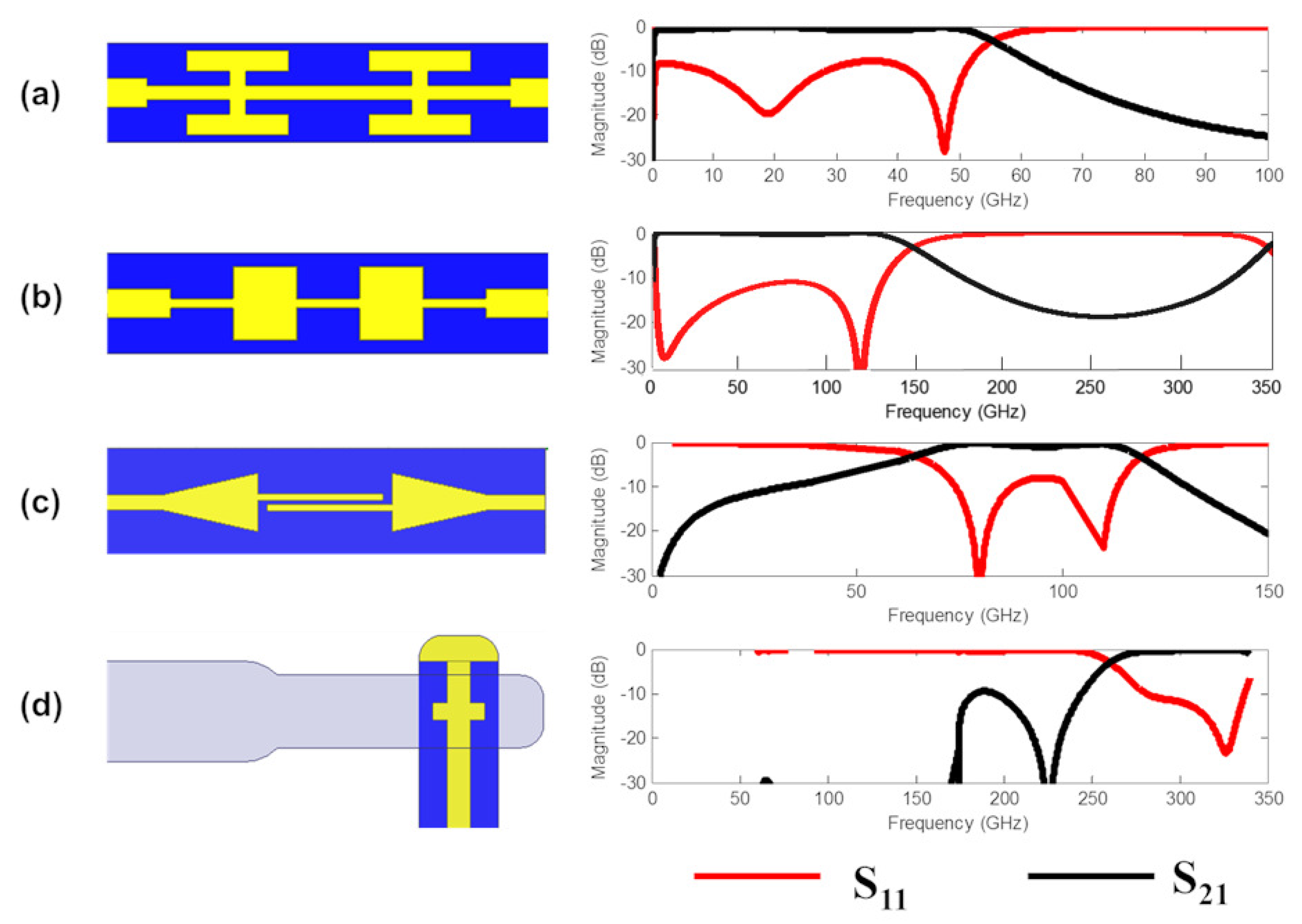
From Figure 1 we can observe that the radiofrequency signal is coupled from a rectangular waveguide to the microstrip line where the diodes are placed. The matching lines that adjust the diode embedding impedance and the corresponding filters for IF, LO and RF port isolation have been optimized. A top view of the passive elements and their simulated response using the commercial software HFSS are shown in Figure 2.
The first filter corresponds to a low-pass filter for IF frequency. In this case, a hammer-head configuration has been selected, see Figure 2a, because of its compactness and good rejection. In Figure 2b the RF low-pass filter is shown. This filter rejects the RF signal and only lets the LO signal pass; a stepped impedance configuration has been chosen in this case. This kind of filter, which consists of quarter-wavelength-long alternating low- and high-impedance sections, presents good rejection and wide bandwidth with a narrower footprint than other filter configurations. The last necessary filter is a high-pass filter, in this case a DC-Block, which lets the LO signal pass to the circuit and rejects the other frequencies, Figure 2c.
A transition that couples the RF signal received in the antenna to the microstrip line in which the planar filters are implemented is also necessary; see Figure 2d. This transition consists of an E-probe optimized to maximize the power coupled to the microstrip line at the RF frequency. Furthermore, this transition also works as a high-pass filter for the IF and the LO signals, so that the isolation at the RF port is high. Finally, one end is connected to the antiparallel Schottky diode pair (APDP) and the other one is connected to the metal housing block to provide the required DC grounding for the APDP.
From the load–pull analysis of the fourth-harmonic mixer, the optimum embedding impedance at LO and RF frequencies have been calculated. These impedances are and for LO and RF frequencies, respectively. The dimensions of the matching lines were calculated in order to implement these optimum impedances so that the mixer conversion losses were minimized.
2.3. Harmonic Balance
Once the passive circuits had been optimized separately, the whole structure was simulated in Ansys HFSS for obtaining the linear electromagnetic behavior of the whole passive components (transitions and filters). Then the S-Parameters of the structure were imported to Keysight ADS software. In this software the non-linear behavior of the Schottky diodes is taken into account using the harmonic balance analysis, where the fundamental frequencies are RF and LO and we consider a maximum mixing order of 11. In this analysis the LO power has been swept from 3 to 12 dBm, in order to take into account the fact that the power generated by the integrated LO can be lower than the nominal value and also suffer losses. The RF signal input frequency has been swept from 298 GHz to 310 GHz, while keeping the IF fixed to 2 GHz. This implies that the LO frequency had to be adjusted accordingly, since .
The minimum conversion loss, 10.5 dB, is achieved at 302 GHz when the LO power is 12 dBm. The 3-dB bandwidth for this power level is 9 GHz (between 298 and 307 GHz), which represents 3 %. The mean CL for the whole band is 13.3 dB. For lower power levels the performance worsens: both the CL and the DSB ENT (ENT) increase. In addition, the bandwidth where the ENT is low narrows. For 6 dBm LO power the mean conversion loss increases up to 16.7 dB. Similarly, the ENT increases from 3000 K for 12 dBm to 10,000 K for 6 dBm. If the local oscillator power is 3 dBm the diodes are under-pumped and the performance degrades. In this case the conversion losses and ENT are higher than 20 dB and 30,000 K, respectively. These results are shown in Figure 3, where they are compared with the experimental results.
3. Fabrication and Experimental Results
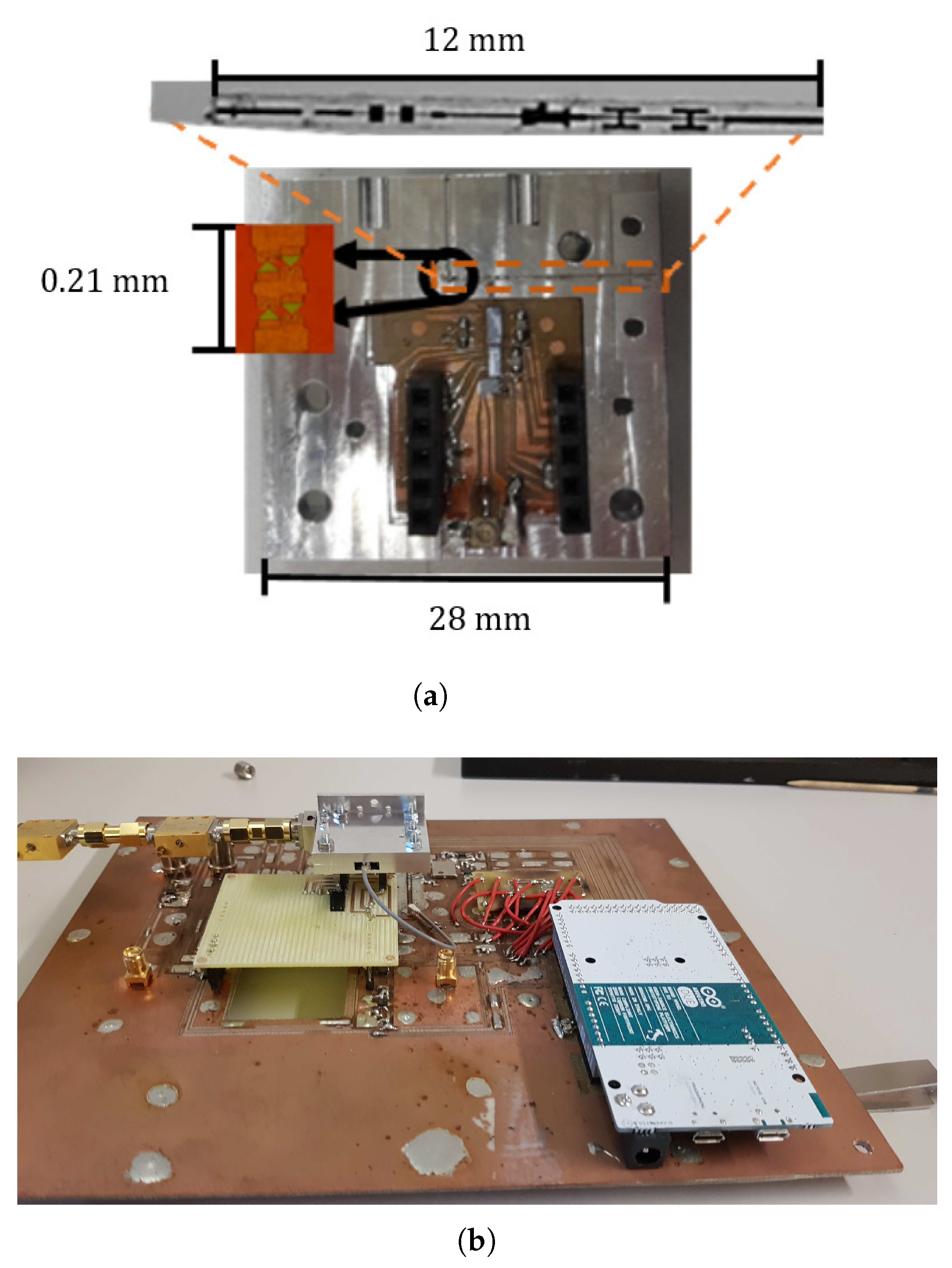
The manufacturing process combined photolithography for the circuits on a COC substrate and CNC micromachining for the the metallic housing block. The Schottky diodes were fabricated by the United Monolithic Semiconductors (UMS) foundry. Finally, the diodes were fixed onto the circuits with silver loaded epoxy (EPOTEK H20E). The MMICs for the local oscillator were soldered onto a 670 m thick Rogers 3210 substrate. Its frequency is controlled by means of a phase-lock loop, which was mounted in a external board and controlled by an Arduino Due. Photographs of all these circuits are shown in Figure 4.
For characterization, the Y-Factor gain method was used [16]. A schematic of the setup for Y-Factor characterization of the mixers is shown in Figure 5. The hot load is obtained by placing a piece of WAVASORB RAM material in front of the RF antenna. For the cold load measurement, the RAM material is cooled down in a container with liquid nitrogen and then placed in front of the RF antenna. Using the power difference, the Y-Factor is calculated; thus, the DSB equivalent noise temperature of the receiver is obtained. The mixer equivalent noise temperature and conversion loss are then obtained by removing the IF chain contribution. The IF chain consists of two GAMP0100.0600SM10 LNA amplifiers with 35 dB gain and 1.8 dB NF. Their output was connected directly to a Keysight N9030A spectrum analyzer, where the power at 2 GHz was measured. A 20 dBi standard gain horn antenna was connected to the RF port of the mixer and the Y-Factor technique was applied as described above.
A photograph of the fabricated prototype and the measurement setup can be seen in Figure 4.
The mixer characterization results are shown in Figure 3, where the comparison between the measured and the simulated performance can be observed. The minimum and mean measured conversion losses for the range between 298 and 310 GHz are 14 and 18 dB, respectively. Regarding the DSB equivalent noise temperature, the minimum and mean values are 9600 and 26,000 K, respectively. There is good agreement from 298 to 304 GHz between these results and the predictions using around 6 dBm LO power. For higher frequencies (304–310 GHz) the measured performance shows a difference of around 3 dB with respect to the simulated performance using ∼6 dBm LO power. According to the datasheets of the COTS components of the LO, the output power should be ∼10 dBm. However, the similar performance to the simulated case using ∼6 dBm indicates that the amount of LO power pumping the diodes might be lower than this LO source expected output power. This can be ascribed to losses in the circuits and to the output power being lower than the nominal level. This behavior is similar to that reported in [8], where a similar integrated LO was used. Unfortunately, with the current configuration the LO power cannot be measured to confirm this hypothesis. In addition to this, tolerance errors in fabrication and the manual positioning of the diodes can also contribute to the losses.
4. Conclusions
In this paper we have described the design and evaluation of a fourth-harmonic mixer with an integrated MMIC-based LO. This cost effective solution allows the use of low-frequency LO sources based on COTS components, which can be developed on planar technology. The results show good performance, similar to the state-of-the-art for fourth-harmonic mixers (see Table 1) and a little worse than subharmonic mixers working in the same frequency range. The performance is limited for two main reasons. First, the available LO power; future steps would consider integrating an amplifier at the output of the second MMIC frequency doubler in order to increase the final available LO power. The second reason is the manual positioning of the diodes, which may introduce misalignments, besides the additional resistance caused by the silver epoxy used for fixing the diodes. This could be solved by using GaAs membrane or other substrateless technology that allows the integration of the diodes during the fabrication of the circuitry. Nevertheless, this prototype demonstrates the possibility of integration of a full THz receiver in the same single packaging metallic block, with the consequent reduction of mass and volume.
Author Contributions
Conceptualization, J.M.P.-E. and I.E.; methodology, J.M.P.-E.; validation, J.M.P.-E. and I.E.; investigation, J.M.P.-E., C.Q. and I.E.; data curation, J.M.P.-E.; writing—original draft preparation, J.M.P.-E.; writing—review and editing, I.E.; funding acquisition, R.G. and I.E. All authors have read and agreed to the published version of the manuscript.
Funding
This research was funded by the Spanish MINECO, Project No. TEC2016-76997-C3-1-R, and by the Spanish State Research Agency, Project No. PID2019-109984RB-C43/AEI/10.13039/501100011033.
Institutional Review Board Statement
Not Applicable.
Informed Consent Statement
Not Applicable.
Data Availability Statement
Not Applicable.
Conflicts of Interest
The authors declare no conflict of interest.
Abbreviations
The following abbreviations are used in this manuscript:
| ADS | Advanced design system |
| CL | Conversion loss |
| COC | Cyclic olefin copolymer |
| COTS | Commercial-off-the-shelf |
| DSB | Double side band |
| ENT | Equivalent noise temperature |
| HFSS | High-frequency structure simulator |
| IF | Intermediate frequency |
| LO | Local oscillator |
| MMIC | Monolithic microwave-integrated circuit |
| UMS | United monolithic semiconductor |
| VCO | Voltage-controlled oscillator |
| RF | Radiofrequency |
References
- Thomas, B.; Alderman, B.; Matheson, D.; De Maagt, P. A Combined 380 GHz Mixer/Doubler Circuit Based on Planar Schottky Diodes. IEEE Microw. Wirel. Components Lett. 2008, 18, 353–355. [Google Scholar] [CrossRef]
- Treuttel, J.; Maestrini, A.; Alderman, B.; Wang, H.; Matheson, D.; De Maagt, P. Design of a combined tripler-subharmonic mixer at 330 GHz for multipixel application using European Schottky diodes. In Proceedings of the 21st International Symposium on Space Terahertz and Technology, Oxford, UK, 23–25 March 2010. [Google Scholar]
- Ederra, I.; Azcona, L.; Alderman, B.E.J.; Laisne, A.; Gonzalo, R.; Mann, C.M.; Matheson, D.N.; De Maagt, P. A 250 GHz Sub-Harmonic Mixer Design Using EBG Technology. IEEE Trans. Antennas Propag. 2007, 55, 2974–2982. [Google Scholar] [CrossRef]
- Torres-García, A.E.; Pérez-Escudero, J.M.; Teniente, J.; Gonzalo, R.; Ederra, I. Silicon Integrated Subharmonic Mixer on a Photonic-Crystal Platform. IEEE Trans. Terahertz Sci. Technol. 2021, 11, 79–89. [Google Scholar] [CrossRef]
- Guo, C.; Shang, X.; Lancaster, M.J.; Xu, J.; Huggard, P.G. A 290–310 GHz Single Sideband Mixer with Integrated Waveguide Filters. IEEE Trans. Terahertz Sci. Technol. 2018, 8, 446–454. [Google Scholar] [CrossRef] [Green Version]
- Reck, T.; Jung-Kubiak, C.; Siles, J.V.; Lee, C.; Lin, R.; Chattopadhyay, G.; Mehdi, I.; Cooper, K. A Silicon Micromachined Eight-Pixel Transceiver Array for Submillimeter-Wave Radar. IEEE Trans. Terahertz Sci. Technol. 2015, 5, 197–206. [Google Scholar] [CrossRef]
- Thomas, B.; Lee, C.; Peralta, A.; Gill, J.; Chattopadhyay, G.; Sin, S.; Lin, R.; Mehdi, I. A 530–600 GHz Silicon Micro-machined Integrated Receiver Using GaAs MMIC Membrane Planar Schottky Diodes. In Proceedings of the 21st International Symposium Space Terahertz Technology, Oxford, UK, 23–25 March 2010. [Google Scholar]
- Pérez-Escudero, J.M.; Quemada, C.; Gonzalo, R.; Ederra, I. A 300 GHz Combined Doubler/Subharmonic Mixer Based on Schottky Diodes with Integrated MMIC based Local Oscillator. Electronics 2020, 9, 2112. [Google Scholar] [CrossRef]
- Li, Q.; Zhang, B.; Zhang, L.; Xing, D.; Wang, J.; Fan, Y. A 330–500GHz 4th-harmonic mixer using schottky diode. In Proceedings of the 2016 IEEE MTT-S Int. Microw. Workshop Series on Advanced Materials and Processes for RF and THz Applications (IMWS-AMP), Chengdu, China, 20–22 July 2016; pp. 1–3. [Google Scholar]
- Maestrojuan, I.; Ederra, I.; Gonzalo, R. Fourth-Harmonic Schottky Diode Mixer Development at Sub-Millimeter Frequencies. IEEE Trans. Terahertz Sci. Technol. 2015, 5, 518–520. [Google Scholar] [CrossRef]
- Deng, J.; Lu, Q.; Jia, D.; Yang, Y.; Zhu, Z. Wideband Fourth-Harmonic Mixer Operated at 325–500 GHz. IEEE Microw. Wireless Comp. Lett. 2018, 28, 242–244. [Google Scholar] [CrossRef]
- Pérez-Escudero, J.M.; Quemada, C.; Gonzalo, R.; Ederra, I. Comparison of Fourth-harmonic and Combined Doubler/Subharmonic Mixer with integrated MMIC based Local Oscillator. In Proceedings of the 2019 44th International Conference on Infrared, Millimeter, and Terahertz Waves (IRMMW-THz), Paris, France, 1–6 September 2019. [Google Scholar]
- TriQuint Semiconductor. Available online: http://www.datasheet.es/PDF/720881/TGV2204-FC-pdf.html (accessed on 4 August 2017).
- Maestrojuan, I.; Palacios, I.; Ederra, I.; Gonzalo, R. Use of COC substrates for millimeter-wave devices. Microw. Opt. Technol. Lett. 2014, 57, 371–377. [Google Scholar] [CrossRef]
- Pérez-Moreno, C.G.; Grajal, J.; Viegas, C.; Liu, H.; Powell, J.; Alderman, B. Thermal analysis of high-power millimeter-wave Schottky diode frequency multipliers. In Proceedings of the 2016 Global Symposium on Millimeter Waves (GSMM) and ESA Workshop on Millimetre-Wave Technology and Applications, Espoo, Finland, 6–8 June 2016; pp. 1–4. [Google Scholar] [CrossRef]
- Agilent Technologies. Noise Figure Measurement Accuracy—The Y Factor Method; Application Note 57-2; Agilent Technology: Palo Alto, CA, USA, 2014. [Google Scholar]
- Schur, J.; Ruf, M.; Schmidt, L.P. Design of a 4th harmonic Schottky diode mixer for THz frequencies. In Proceedings of the 2007 Joint 32nd International Conference on Infrared and Millimeter Waves and the 15th International Conference on Terahertz Electronics, Cardiff, UK, 2–9 September 2007; pp. 756–757. [Google Scholar]
- Sobis, P.J.; Emrich, A.; Stake, J. A Low VSWR 2SB Schottky Receiver. IEEE Trans. Terahertz Sci. Technol. 2011, 1, 403–411. [Google Scholar] [CrossRef] [Green Version]
- Thomas, B.; Maestrini, A.; Beaudin, G. A low-noise fixed-tuned 300-360-GHz sub-harmonic mixer using planar Schottky diodes. IEEE Microw. Wirel. Components Lett. 2005, 15, 865–867. [Google Scholar] [CrossRef]
Figure 1.
Configuration of the whole fourth-harmonic mixer with integrated MMIC local oscillator. (a) Schematic of the fourth-harmonic mixer circuit. (b) Top view of the design prototype.
Figure 1.
Configuration of the whole fourth-harmonic mixer with integrated MMIC local oscillator. (a) Schematic of the fourth-harmonic mixer circuit. (b) Top view of the design prototype.

Figure 2.
Top view and predicted response of the mixer passive circuits: (a) IF Hammer-head filter; (b) RF stepped impedance low-pass filter; (c) LO DC-Block and (d) RF waveguide to microstrip E-Probe transition.
Figure 2.
Top view and predicted response of the mixer passive circuits: (a) IF Hammer-head filter; (b) RF stepped impedance low-pass filter; (c) LO DC-Block and (d) RF waveguide to microstrip E-Probe transition.

Figure 3.
Comparison between the experimental performance of the fourth-harmonic mixer for an intermediate frequency, GHz, and its simulated performance for various LO powers. (a) DSB equivalent noise temperature and (b) conversion losses.
Figure 3.
Comparison between the experimental performance of the fourth-harmonic mixer for an intermediate frequency, GHz, and its simulated performance for various LO powers. (a) DSB equivalent noise temperature and (b) conversion losses.

Figure 4.
Photographs of (a) top view of the subharmonic mixer and local oscillator in the metallic block; (b) measurement setup for the fourth-harmonic mixer characterization.
Figure 4.
Photographs of (a) top view of the subharmonic mixer and local oscillator in the metallic block; (b) measurement setup for the fourth-harmonic mixer characterization.

Figure 5.
Schematic of the Y-Factor setup used for mixer characterization.


Table 1.
State-of-the-art of fourth-harmonic Schottky diode mixers working at frequencies similar to this work.
Table 1.
State-of-the-art of fourth-harmonic Schottky diode mixers working at frequencies similar to this work.
| Ref. | Type | Frequency (GHz) | CL (dB) | ENT (K) |
|---|---|---|---|---|
| [9] | Fourth Harmonic | 369–477 | 14 (Simulation) | - |
| [10] | Fourth Harmonic | 430–460 | 14 | 10,000 |
| [11] | Fourth Harmonic | 320–500 | 12 | - |
| [17] | Fourth Harmonic | 572–628 | 15 | - |
| [18] | Subharmonic | 290–310 | 9.5 | 2300 |
| [19] | Subharmonic | 300–360 | 6.5 | 1270 |
| This work | Fourth Harmonic | 298–310 | 14 | 9600 |
Publisher’s Note: MDPI stays neutral with regard to jurisdictional claims in published maps and institutional affiliations. |
© 2021 by the authors. Licensee MDPI, Basel, Switzerland. This article is an open access article distributed under the terms and conditions of the Creative Commons Attribution (CC BY) license (https://creativecommons.org/licenses/by/4.0/).
Share and Cite
MDPI and ACS Style
Pérez-Escudero, J.M.; Quemada, C.; Gonzalo, R.; Ederra, I. A Millimeter-Wave 4th-Harmonic Schottky Diode Mixer with Integrated Local Oscillator. Appl. Sci. 2021, 11, 7238. https://0-doi-org.brum.beds.ac.uk/10.3390/app11167238
AMA Style
Pérez-Escudero JM, Quemada C, Gonzalo R, Ederra I. A Millimeter-Wave 4th-Harmonic Schottky Diode Mixer with Integrated Local Oscillator. Applied Sciences. 2021; 11(16):7238. https://0-doi-org.brum.beds.ac.uk/10.3390/app11167238
Chicago/Turabian StylePérez-Escudero, José M., Carlos Quemada, Ramón Gonzalo, and Iñigo Ederra. 2021. "A Millimeter-Wave 4th-Harmonic Schottky Diode Mixer with Integrated Local Oscillator" Applied Sciences 11, no. 16: 7238. https://0-doi-org.brum.beds.ac.uk/10.3390/app11167238
Note that from the first issue of 2016, this journal uses article numbers instead of page numbers. See further details here.