1. Introduction
The silicon detectors used to reconstruct the tracks of charged particles (particle trackers) in collider experiments need to operate at stable temperature to maximise the signal to noise ratio. Furthermore, when subject to radiation, the operational temperature must be lowered below 0
to minimise the detrimental effects of radiation on their performance [
1].
The Large Hadron Collider at CERN is undergoing an upgrade preparing it for the High Luminostiy programme (HL-HLC) starting in 2026 [
2]. This upgrade is planned to increase by a factor of 10 the luminosity, i.e., the density of the particles created by the collision. This will in turn increase of an order of magnitude the radiation level in the detectors [
3]. As the level of irradiation of silicon detector grows, the temperature required to maintain the performance of the silicon sensor decreases, becoming more and more critical at highly irradiated environments [
4]. The two largest particle detectors in the world, ATLAS and CMS installed at LHC, are going through major upgrades to get ready for a 10 year-long operation along with the High Luminosity version of the accelerator. Such upgrades involve the replacement of the present particle trackers with large silicon detectors of new generation, capable of coping with the increased density of tracks.
The new silicon trackers will require a new cooling system, capable of evacuating from the detector volume a nominal power up to 300 for ATLAS and 500 for CMS, while ensuring a temperature of the refrigerant in the detector heat exchangers down to .
1.1. CO2 Cooling for Particle Trackers
CO
2 evaporative cooling systems based on mechanically pumped loops are more and more frequently used for particle trackers, because they allow for the use of smaller tubes (hence reducing the amount of material in the tracking region), while presenting more favourable thermo-physical properties compared to other refrigerants. This approach has been successfully used for the first time in the LHCb Velo detector since 2008 [
5]. Since then, it has been adopted also for the ATLAS Inner b-Layer (IBL) detector since 2014 [
6] and the CMS “Phase-1” Pixel detector since 2016 [
7].
The specific CO
2 pumped loop developed for the thermal management of silicon detectors at LHC, commonly referred to as 2PACL [
8], is an oil-free system pumping subcooled liquid CO
2 into the detectors via small pipes (around 2
ID pipes), bringing it in saturated condition at the inlet of the detector heat exchangers, to efficiently evacuate all the heat produced by the electronics mounted on the silicon detectors [
9] while keeping the silicon sensors very stably at the desired temperature set point.
The 2PACL system will be installed 100 underground in a cavern hosting several services for the operation of the detector. However, it requires an external system to cool down the liquid CO2 before pumping it towards the detector and condensate the two-phase CO2 coming back from the detector. It is actually the secondary loop in a more complex cascade of system: the heat evacuated from the detector is exchanged with a primary loop, responsible for transporting the heat to the surface and to maintain the secondary loop CO2 subcooled to below . In particular, the more stringent thermal requirements imposed by the harsh HL-HLC environment push to lower the subcool target for the secondary loop CO2 down to .
The design of an innovative primary system capable of achieving this ambitious goal is the focus of a research programme launched in common by CERN and NTNU.
1.2. R744 Primary Systems
Following the 2014’s European Parliament resolution for the transition over HFCs [
10], the commitment of CERN for a greener future and the presence of low temperature R744 chillers in the market (operating between
and
), the ATLAS and CMS experiments decided to use only CO
2 for the new cascade system designed to cool their future trackers.
However, a conventional R744 chiller system off the shelf would not comply with the particular requirements of both detectors. Therefore, the refrigeration process, the equipment and control logic associated had to be rethought.
The system is non-standard in many aspects, and therefore few prototypes are foreseen to check beforehand that the proposed solution will be able to reliably and stably cope with all technical challenges. The first prototype built is the subject of this work.
1.3. Technical Challenges
The LHC accelerator is located in a 27
long circular tunnel excavated at a depth of the order of 100
from the surface. As illustrated in
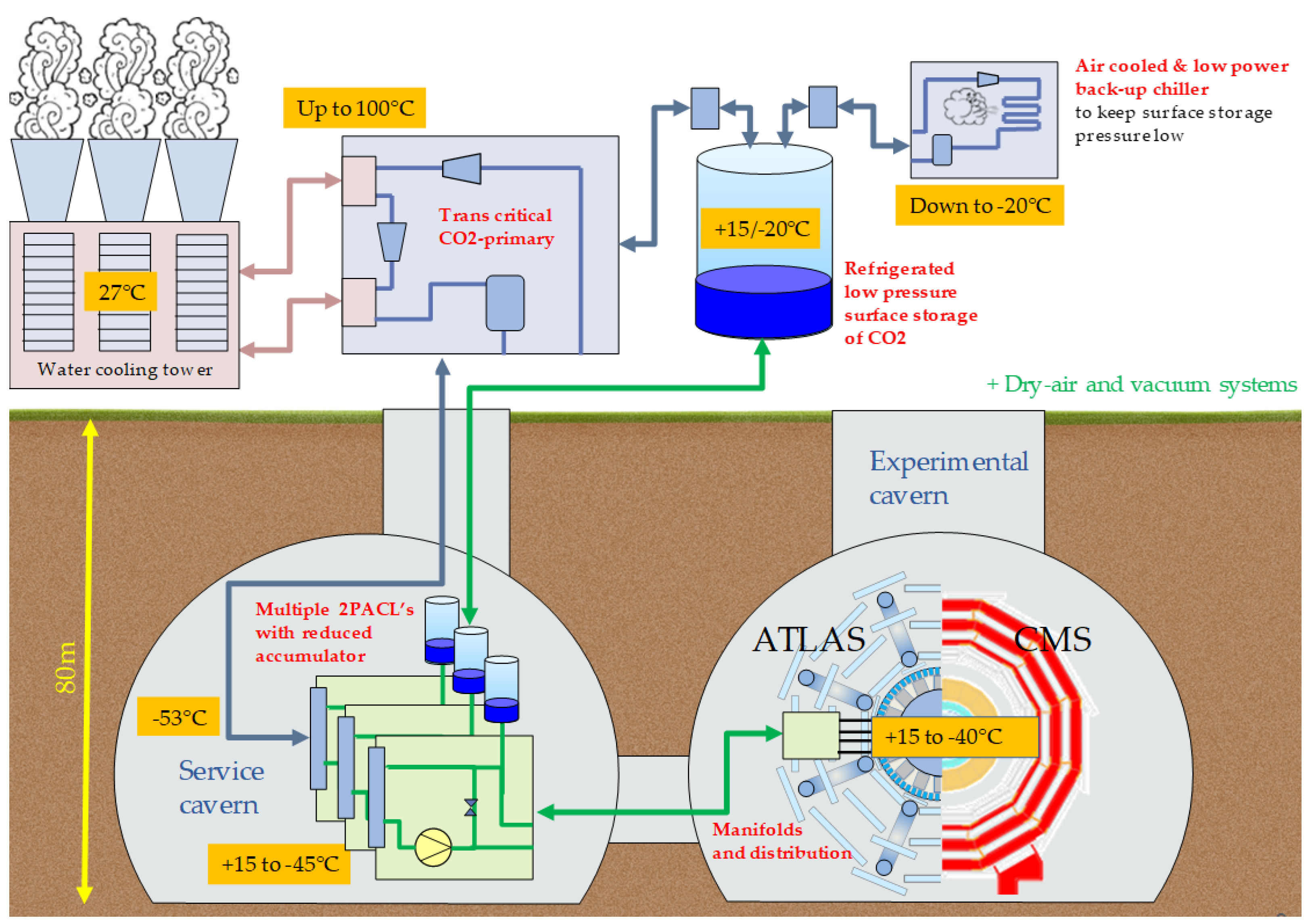
Figure 1, the LHC experiments are built around the accelerator and are housed in large underground halls conventionally named “caverns”: the detector itself occupies the so-called “experimental cavern”, while all ancillaries that are not strictly required to be placed in the immediate closeness of the detectors are housed in a parallel hall called “service cavern”. This is the case of the secondary 2PACL system.
However, due to space limitations, to the amount of heat produced and to the risks of asphyxiation in case of leak, ATLAS and CMS cannot afford to install underground also the large R744 chiller required as primary system. The primary system needs thus to be installed on surface, inside a dedicated building with all the space and security features needed. Its connection to the 2PACL system in the service cavern is indeed one of the challenges to be tackled, due to the complex pipe routing, estimated to be ≈ 300 long with around 90 of height difference and very limited space for integration. In order to cope with the space constraints, it has been decided to establish this connection with non-insulated pipes.
The LHC beam time allocated to the experiments is extremely valuable and it is mandatory to avoid any stoppage of the detector while the beam is circulating. Therefore, the highest level of reliability is the top priority for all the experiments’ detectors and their vital ancillary systems, including the cooling.
Underground, the pressure of the R744 primary shall be as low as possible at the evaporator level to cool the liquid CO2 pumped by the 2PACL secondary loop down to lowest possible temperature. The physical limit is of course , corresponding to the CO2 triple point at bar): therefore, the challenge translates into minimising that safety margin, protecting from the risk of getting below the triple point due to the pressure drop along the line. Moreover, with non-insulated pipes at room temperature and such low return pressure, the superheating of the return line will be significantly large (≈ 70 K).
The oil circulating in the primary system will tend to migrate to the coldest point of the installation, which will be located underground in this particular case. Considering the height difference of around 90 and the complex routing of the transfer lines, pumping the oil accumulated underground back to the system does not seem feasible. Hence, the oil separation shall be extremely efficient.
Finally, both experiments require the temperature to be kept stable in nominal operation, at startup and during stoppage to avoid any potential damage to the sensor modules. The system is therefore also required to cope with a significant range of heat loads, which will vary from a minimum of 50 during stoppage up to a maximum of 920 at startup. The amount of cooling provided to the detector’s evaporator is ultimately controlled by the secondary loop which is independent from the primary system. The primary chiller shall thus keep the process stable to finely control the return pressure at ±250 bar during operation ( ), while the system shall also be able to react quickly to transient regimens.
1.4. Modular R744 Chiller
To address the high level of reliability and large amplitude of cooling capacity to be requested throughout the lifetime of the detector, a novel modular design for the R744 chillers has been proposed [
11].
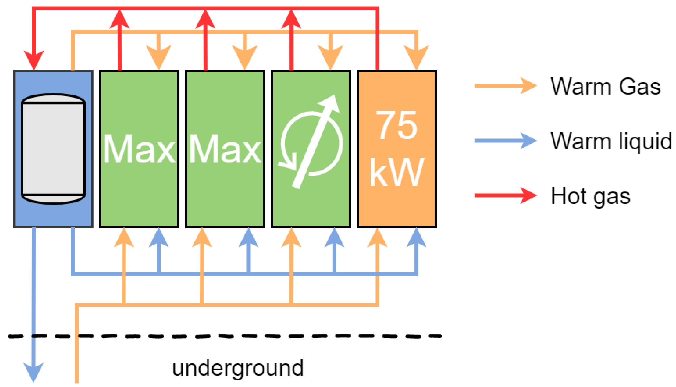
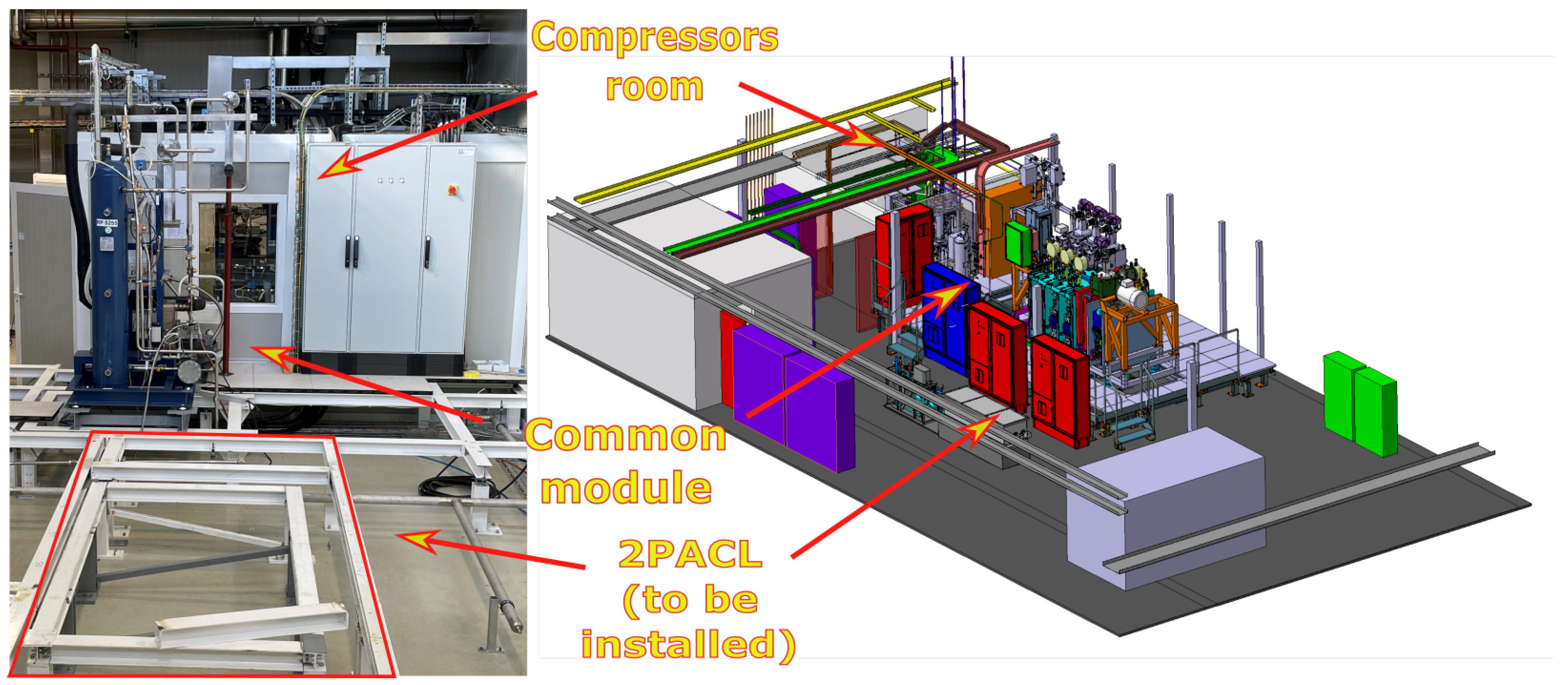
Inside the dedicated buildings it is foreseen the installation of a group of interconnected vapour-compressing modules (compressor slices) as illustrated in
Figure 2, with dedicated air gas coolers and a common equipment module with water gas cooler and receiver.
Each compressor slice is designed to cope with the vapour-compressing and heat rejection needs for a given cooling capacity request and will solely operate in case of need. Decoupling the whole unit into independent modules enables the possibility for the maintenance teams to intervene with no risk of perturbing the process.
In case of an unexpected shutdown of the electrical network, the system needs to keep a minimum cooling of the detectors while it evacuates the remaining heat (minimum requirement of 50 ). With a modular scheme, it will be possible to plug the power cabinets of a few compressor slices to a diesel power supply units, which is quite an advantageous feature in terms of cost and footprint for the whole installation.
The R744 liquid supply to the services cavern and the return of evaporated gas to the compressor slices is established via long pipes with no thermal insulation and hence, at ambient temperature. ATLAS and CMS final units will share the same design but in the number of compressor slices modules and the dimensions of connection pipelines [
11].
2. Technical Solution
For ultra-low temperature applications (temperatures below
according to Regulation (EU) No 517/2014) like the freezing and storage of fish, it is common to use blends of R744 with other natural refrigerants with lower freezing points like the R170 and R1150 [
12]. Unfortunately, these refrigerants are not applicable to our application as they are flammable and hence, an innovative solution had to be found to manage the required cooling temperatures using CO
2 only.
The refrigeration cycle concept adopted [
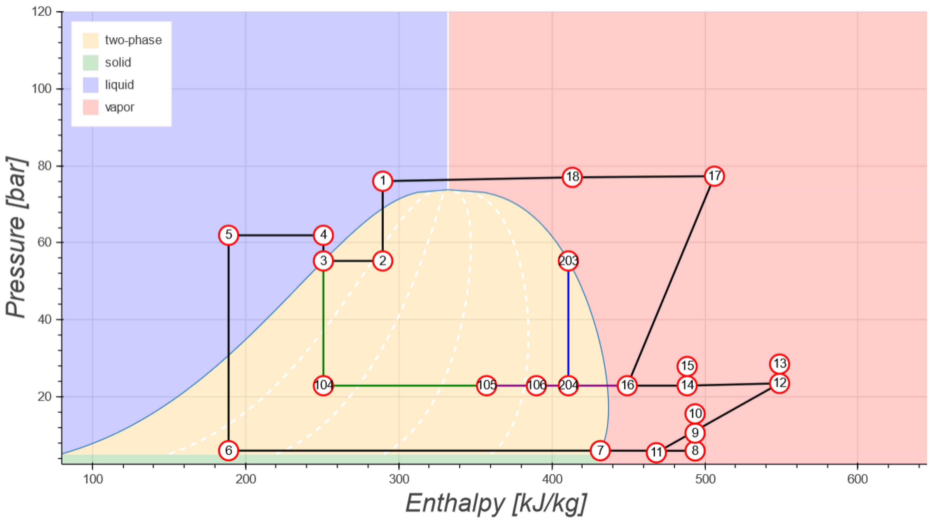
9] is illustrated in
Figure 3 and considers the following assumptions: outlet temperature of transcritical gas cooler of 30
, interstage gas cooler outlet temperature of 30
, high side pressure of 76 bar, evaporation temperature of
, superheat of 0
for evaporator and 10
at interstage, isentropic compression process and isenthalpic expansion.
In order to achieve such aggressive goals, several unusual design solutions have been considered for this cycle: in the following, the rationale behind the main specific design choices is exposed.
2.1. Booster Transcritical Cycle
Given that evaporator’s liquid supply is achieved through non-insulated pipes, it would be inefficient keeping the receiver at a temperature below the temperature underground (statepoint 2 around 20 ). Moreover, as the CO2 has a rather low critical temperature of 31 and a minimum level of flash gas shall be produced in the receiver to sustain the refrigeration cycle, the solution will inevitably pass by a transcritical cycle to avoid any temperature control close to the triple point singularity.
The most adapted solution to compress CO2 gas returning from underground with a pressure below 6 bar and at room temperature (very large superheating) to transcritical pressures is a transcritical booster compression cycle.
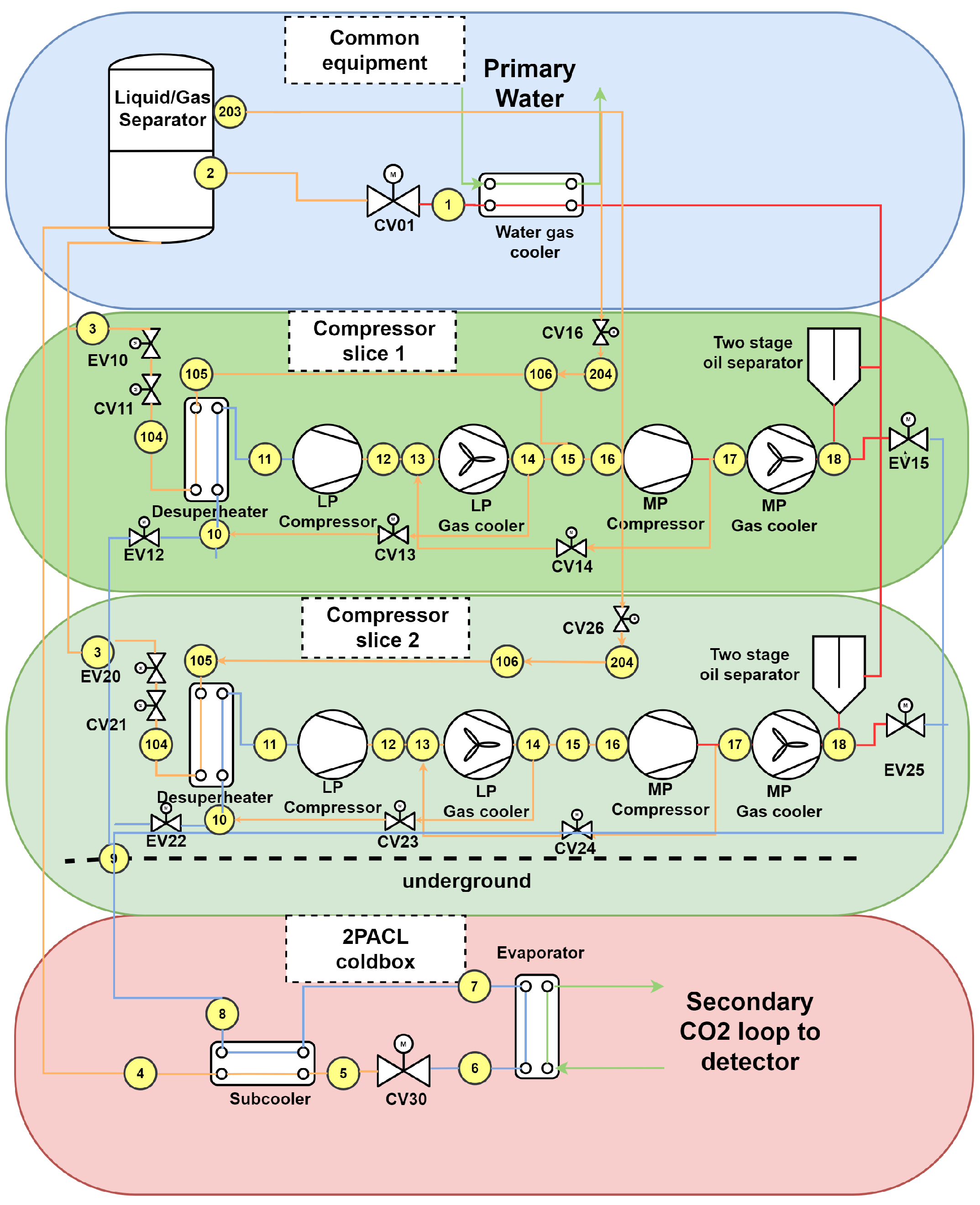
2.1.1. Two-Phase Desuperheater
Considering the warm return gas temperature, a desuperheater is needed to avoid too high discharge temperatures on the low pressure (LP) compressor and make vapour compression more efficient. To desuperheat the suction of the LP compressor, instead of injecting liquid into LP compressor suction side, that could potentially cause the production solid CO2, a microplate heat exchanger has been adopted, using the liquid injected into the MP compressor suction to control its suction superheating (statepoints 10→11 and corresponding 104→105). This way, the desuperheating becomes a by-product of the interstage superheating control simplifying greatly the control logic and the LP compressor is able to operate with suction pressures below triple point (large superheat is still imposed by design). Moreover, the two-phase heat transfer with partial evaporation enhances significantly the heat transfer coefficient on the evaporator part thanks to the high degree of wetted surfaces.
2.1.2. Internal Heat Exchanger
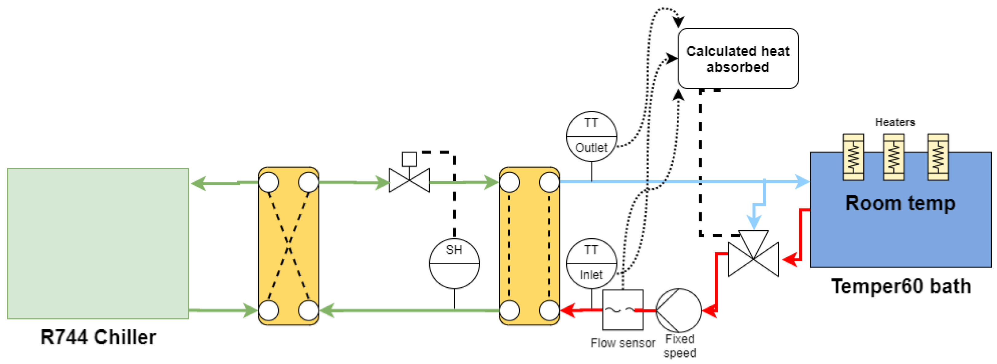
Prior to the evaporator installed underground, a heat exchanger is installed to subcool the R744 at room temperature coming from the surface with the cold return gas from the evaporator that returns back to the surface the refrigerant at room temperature (statepoints 4→5; 7→8). This way, the system increases the cooling capacity of the evaporator. Furthermore, to minimise superheating losses which can be very penalising in high pressure fluids like the CO2, the cooling capacity control of secondary loop also integrates the possibility to control the outlet vapour quality.
2.1.3. Flash Gas Injection
With the proposed modular arrangement the compressor units (apart from the first one) shall be pressurised and start up before being connected to the gas return line and start regulating the return pressure. Otherwise, the pressurisation would be out of control (chiller has no control on flow across evaporator) causing instabilities in the process that must be avoided.
The other way proposed to pressurise the compressor is via flash gas injection at the interstage pressure while keeping the LP compressor by pass valve with a minimum opening to pressurise the low pressure side.
The flash gas ends also participating with the liquid injection and intermediate gas cooler in the cooling of the gas at intermediate pressure (statepoints 203→204) and in the pressurisation of the oil reservoir like in conventional chillers.
5. Discussion
5.1. Oil and CO2 Back-Flow
The non-conventional way used to pressurise the compressor slices causes reversed oil and CO2 into the oil separators which was not anticipated. This issue affects the control of the process (lack of control of pressurisation and receiver pressure) and can potentially damage oil dumping valves and filters inside oil separators. To avoid the oil back-flow, a modular system like the one hereby proposed shall include a one way valve, the oil dumping valves and the oil valves.
5.2. Quality of Oil Separation
The quality of oil separation could only be evaluated qualitatively by checking amount of oil accumulated into the low side of the evaporator. Some oil has been spotted but there was no way to properly quantify the level of oil separator. Hence, for the future units, an inline THC analyser with a 1 ppm measurement precision shall be included after the oil separator to evaluate the quality of oil separation in real time.
5.3. Over-Pressurisation at Stoppage
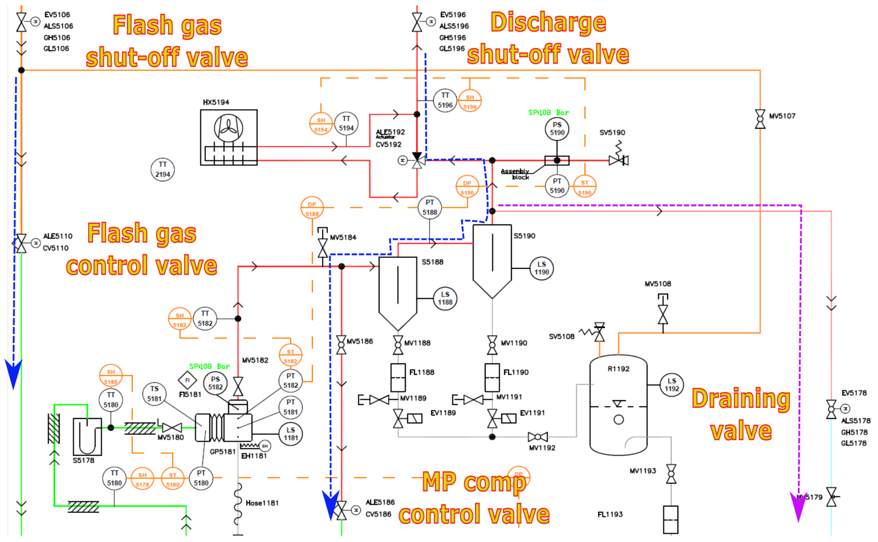
The low pressure side of the first prototype has been designed for 60 bar, already anticipating uncontrolled over-pressurisation during commissioning of the unit. However, this shall be avoided as the future units will be designed to lower pressures. The main cause for this uncontrolled pressurisation was the open default position of flash gas control valve and bypass control valve of MP compressor, with the paths illustrated by the blue arrows in
Figure 12. As baseline, the compressor slice was designed to be at equalised pressure everywhere once stopped while being drained via draining valve until pressure equalises return line pressure. As the shut-off valves are too slow and pressure in the receiver is high, the safety position of controlled valves had to be rethought. It has been proposed that the flash gas and bypass valve safety position is closed and that the system keeps relying on drain valve to equalise pressure everywhere. The low pressure side will be able to equalise the high pressure side through the MP compressor as it is not tight to reversed flow and the oil reservoir would be kept pressurised above slice. Moreover, one-way valve downstream the shut-off discharge valve has also been proposed to minimise impact in the process once the system is connected to discharge line and rely solely on flash gas injection to pressurise the whole slice.
5.4. Liquid CO2 in Oil Separators
Accumulation of liquid CO2 in the oil separators can be very harmful to the compressors in case the CO2 is emptied to the oil reservoir at the same time there is oil intake on one of the compressors. Looking at the system pipeline routing, the position of the draining point and default position of MP compressor bypass valve are the potential causes for having the draining happen across the oil separators to the low pressure side of compressor slice.
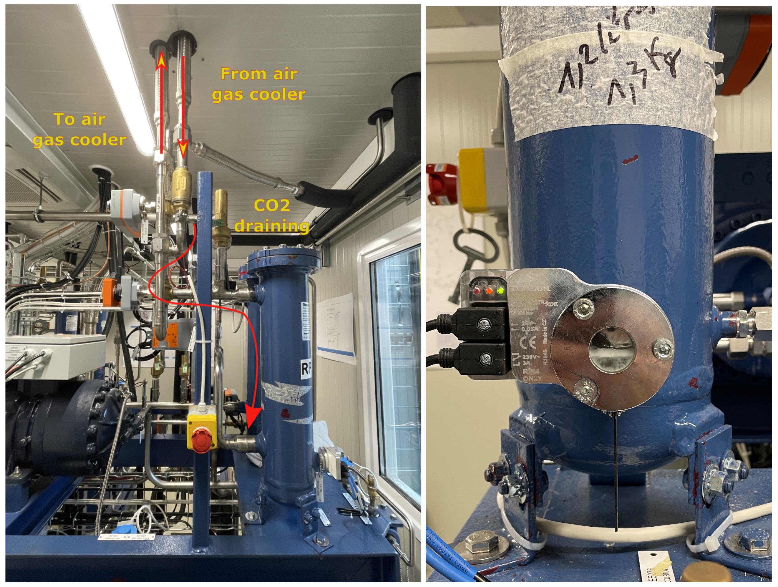
Changing the default position of the MP compressor bypass valve helps in avoiding the flow across oil separators. On top of this, the draining point is proposed to be placed right after the return line from air gas coolers to stay farther from the oil separators.
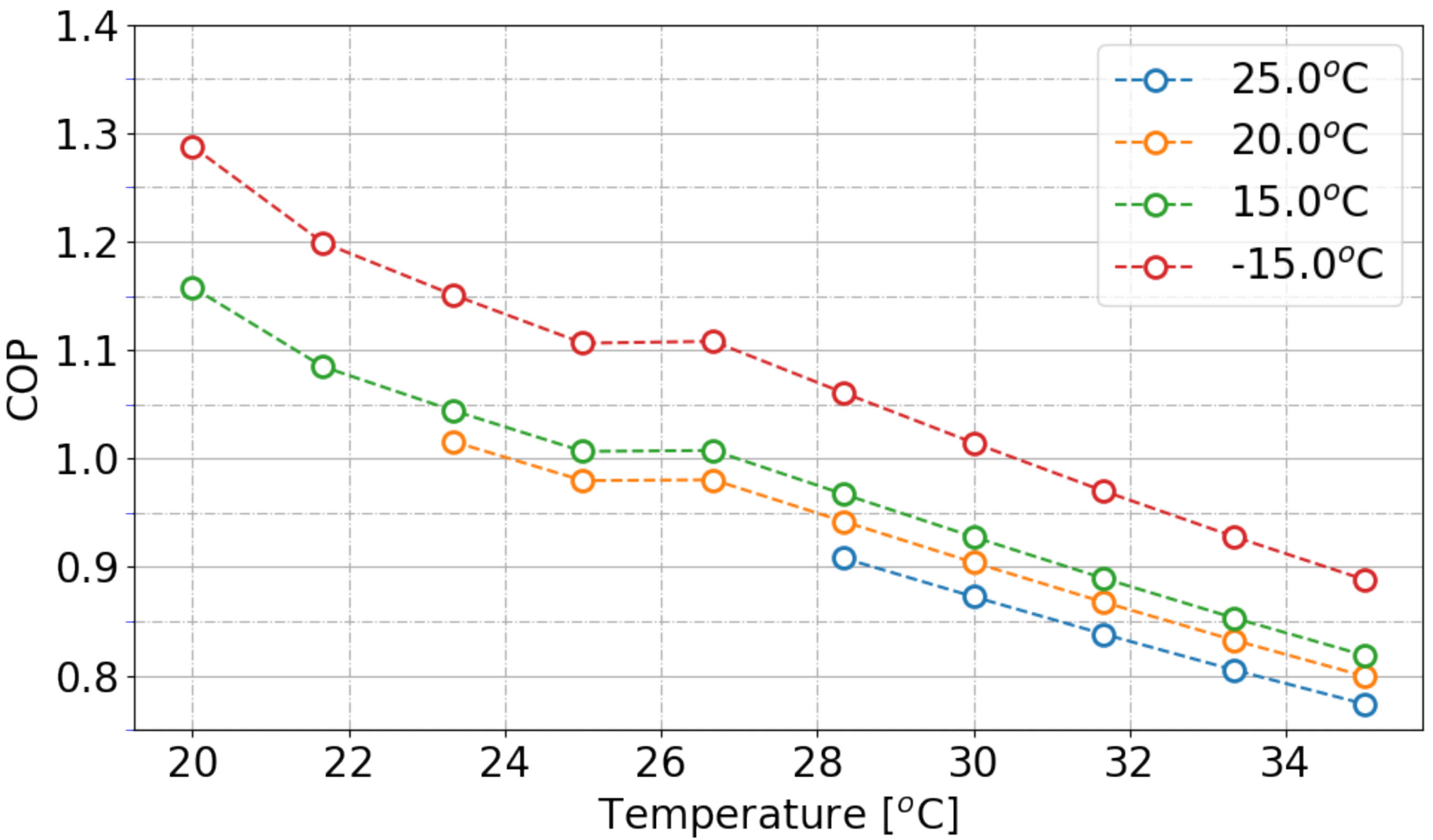
5.5. System’s Performance
The LP compressors presented isentropic efficiencies of 61% and 66% and the MP compressors efficiencies of 68% and 69%. With these efficiencies, the compressor slices managed a COP of 0.92 and 0.94 which is slightly below the COP of 1.1 theoretically expected for a conventional CO
2/CO
2 booster system [
15].
Figure 13 shows how the COP of the cycle is penalised around 10%, by the use of non-insulated receiver and piping. The method used to calculate the COP and used in the concept cycle illustrated is in line with the Gullo et al. investigations [
16].
The COP of the system may benefit from a change of interstage pressure and this shall be investigated during experimental optimisation studies to come. It is also being considered the use of parallel compression and multi-ejectors which together could potentially increase the efficiency of the cycle up to 40% [
16].
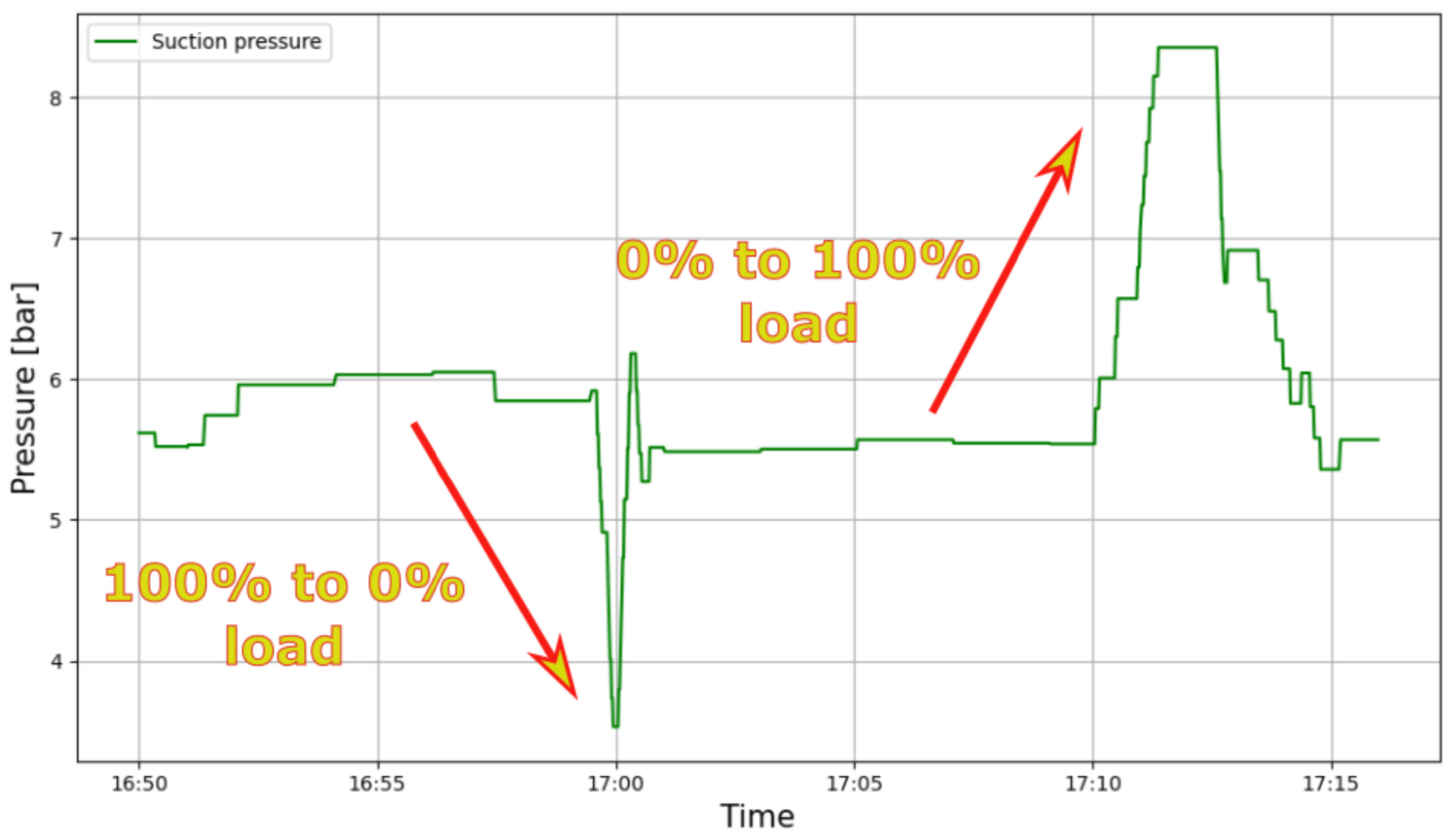
Finally, the system has been capable of coping with sudden changes of load (0% to 100% and from 100% to 0%). Once the load is completely removed the low pressure compressor experiences a sudden pressure decrease, reaching bar for a few seconds before recovering back to the pressure setpoint. The compressor presents no problem reacting to this effect and the large superheat and non-existence of liquid injection is by design safeguarding any potential introduction of solid CO2 at the suction of the compressor.
6. Conclusions and Outlook
The ATLAS and CMS experiments require the primary system to be capable of providing a cooling temperature underground at (corresponding to 6 bar) with a stability of ± . The preliminary commissioning tests hereby presented have been conducted at bar already anticipating the expected 500 bar of pressure drop between the evaporator and the buildings on the surface. The results were important to validate the principle of operation and enlarge the possibilities for the final units.
Amongst the prototypes foreseen before launching the production of the final units, only this first prototype includes two compressor slices. Therefore, this system will keep being a source of important feedback for the definition of the end control logic. This work reports the preliminary results that will precede a forethought testing campaign that will happen in the coming months. Throughout the next tests, it will be investigated how the system’s control shall deal with the management of multiple slices at every case scenario, what are the optimal process setpoints given the chosen components, other different capacity control strategies and finally the reliability of the system in case of major failures. Moreover, the system has been designed so it can operate even below triple point if needed (for example, in case the pressure underground is closer to the triple point pressure of bar). The lowest possible pressure in the evaporator underground will be dictated by the low pressure limit of the design so it will be particularly interesting to evaluate the operation limits.
The next prototype is currently under design, benefiting from the System A preliminary results, and should be ready by the end of this year. This system will comprise one compressor slice only with twice the cooling capacity of System A (two LP compressors) and will serve mainly to investigate the amount of oil carried over to underground by connecting it to the dummy load presented in
Section 3.3 through the ATLAS shaft. A third prototype with only one compressor slice should benefit from the coming testing campaign on System A and shall arrive at CERN by the middle of next year. Together with the other two prototypes, it will provide the feedback needed for the design of the ATLAS and CMS final units that shall arrive by mid 2023.
The studies will proceed and the final return of experience on System A will soon be shared in future publishing.


