Article

Development of Narrow Loop Joint for Precast Concrete Slabs with Fiber-Reinforced Mortar: Experimental Investigation of Material Properties and Flexural Behavior of Joint

1
Department of Civil Engineering and Regional Design, Utsunomiya University, Yoto 7-1-2, Utsunomiya 321-0904, Japan
2
Faculty of Road and Bridge Engineering, The University of Danang—University of Science and Technology, 54 Nguyen Luong Bang, Da Nang 550000, Vietnam
3
DPS Bridge Works Co., Ltd., Ueno 2-1-11, Taito, Tokyo 110-0015, Japan
*
Author to whom correspondence should be addressed.
Submission received: 9 August 2021 / Revised: 28 August 2021 / Accepted: 2 September 2021 / Published: 5 September 2021
(This article belongs to the Special Issue Structural Application of Advanced Concrete Materials)

Abstract

:
In the replacement of the reinforced concrete slab in existing steel girder bridges, a loop joint is commonly used to join precast concrete slabs on site. However, a relatively wide joint is needed, and considerable time and effort are consumed to construct the joint due to the addition of transverse reinforcements to the joint on site. These disadvantages affect the progress of on-site construction and should be addressed, especially when this method is applied to highway bridges, where early traffic opening is necessary in many cases. This study proposes a narrow loop joint that has fiber-reinforced mortar without transverse reinforcements. Several material tests were conducted to determine a suitable material for the joint. A series of flexural loading tests of slabs was conducted to investigate the flexural behavior of the proposed loop joint with the selected material (polyvinyl alcohol (PVA) fibers). The results showed that the flexural capacity and deformation performance of the proposed joint with PVA fibers are equivalent to those of the conventional loop joint.

1. Introduction

Steel girder bridges have been in use for more than 60 years in many countries, such as the United States, Japan, and European countries. The deterioration of these bridges is most evident in reinforced concrete (RC) slabs directly affected by traffic loads. These RC slabs need to be repaired or replaced to maintain the service life of these bridges [1]. In the replacement of these RC slabs, precast (PCa) concrete slabs are widely used to shorten the on-site construction time (as early traffic opening is necessary in many cases) and improve slab durability [2,3,4].
Figure 1 shows a loop joint connecting two precast concrete slabs for (a) conventional loop joint and (b) proposed narrow loop joint without transverse reinforcements in this study. A loop joint, such as that shown in Figure 1a, is conventionally used to join PCa slabs on site in Japan [5,6,7,8]. The force transfer occurring in a loop joint subjected to a flexural moment is schematically shown in Figure 2. The flexural resistance of a joint with a loop reinforcement depends on the bond stress of the straight part and the bearing stress of the curved part [9]. Therefore, the length of the straight part of the reinforcement should be sufficient to ensure bond capacity, and transverse reinforcements need to be added to the joint to improve the bearing capacity of the curved part of the reinforcement. According to the German Institute for Standardization (DIN) 1045 [10], the length of the loop reinforcement inside the joint should be more than 1.5 times the internal diameter of the curved part of the loop reinforcement. Therefore, the joint width should be 250 mm for 13-mm reinforcement, 300 mm for 16-mm reinforcement, and 350 mm for 19-mm reinforcement. Furthermore, tensile stress, i.e., splitting stress, occurs in the transverse direction due to the bearing pressure from the loop [11]. Transverse reinforcements are integrated in the conventional loop joint, as shown in Figure 2, to resist this splitting stress and provide a dowel effect for interlocking the loops.
However, in this method, a relatively large width of the joint is needed, and considerable time and effort are consumed in constructing the joint due to the addition of the transverse reinforcements to the joint on site. These disadvantages affect the progress of on-site construction and should be addressed, especially when this method is applied to highway bridges, where early traffic opening is necessary in many cases. Several methods for joining PCa slabs on site have been developed in recent years to facilitate the arrangement of transverse reinforcements in the joint or reduce the joint width. Abe et al. [12] and Jean et al. [13,14] proposed methods that use headed reinforcements instead of loop reinforcements in the joint. Cheung et al. [15] used high-strength fiber-reinforced cementitious composites to improve the bond strength between reinforcements without loop reinforcement, whereas Sasaki et al. [16] considered a joint with a combination of shear keys and reinforcements with fiber-reinforced concrete. Nguyen et al. [17,18] proposed a joint structure that uses a perfobond strip with steel fiber–reinforced mortar. However, these new joints are still being tested, and their force transfer mechanisms and design methods have not been clarified. Moreover, some of these techniques are expensive because of the structural complexity and the materials used in the joint.
This study proposes a narrow cost-effective loop joint that measures 200 mm in width, has D19 loop reinforcements, and does not have transverse reinforcements, as shown in Figure 1b, to address the disadvantages of the conventional loop joint. A cost-effective loop splice is used along with fiber-reinforced mortar to ensure force transfer in the joint without transverse reinforcements. The joint material can be reduced by 40% through a reduction of the joint’s width and construction time can be reduced by 25% without providing transverse reinforcements as compared to the conventional loop joint.
In this proposed joint, fiber-reinforced mortar with high compressive and tensile strengths should be developed to improve the restraint around the loop reinforcement and to resist the splitting stress due to the bearing pressure from the loop. Therefore, this study conducted several material tests with different types of fibers and volume contents in the mortar. In addition, flexural loading tests were conducted on three specimens with 200-mm width joints and one specimen with a 350-mm width conventional loop joint. The parameters of the flexural loading tests are the materials of the post-casting joint and the overlapping length of the loop reinforcements extruding from two precast slab members. The flexural behavior of the proposed joint is discussed on the basis of the experimental results in comparison with the conventional loop joint.

2. Development of Fiber-Reinforced Mortar for Proposed Loop Joint

2.1. Required Mechanical Properties for Material

The flexural capacity of the loop joint depends on the bond stress of the straight reinforcement part and the bearing stress of the curved reinforcement part [9,10]. In the proposed loop joint, shortening the joint width inevitably reduces the bond stress of the straight part of the reinforcement. In this case, the bearing capacity of the curved part of the reinforcement should be enhanced to fulfill the required flexural capacity of the joint. Therefore, it is necessary to increase the split tensile strength and compressive strength of the joint casting materials that receive the bearing force directly from the loop to ensure the restraining force around the reinforcements.
Moreover, when the joint is subjected to a flexural moment, large flexural cracks can emerge at the interface between the PCa slabs and the joint due to the opening. Hence, joint casting materials should exhibit tensile bond strength to PCa concrete to avoid the above issue. Therefore, this study developed a fiber-reinforced mortar for joints between PCa slabs with high compressive, tensile, and tensile bond strengths.

2.2. Previous Studies on Fiber-Reinforced Mortar
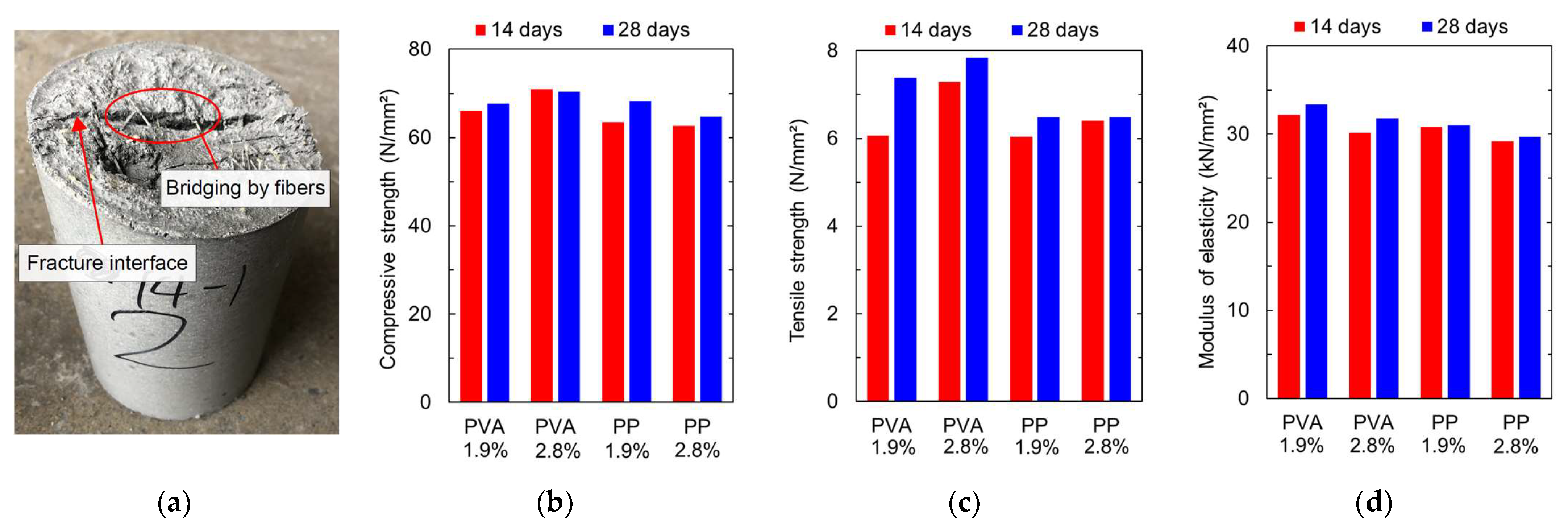
The addition of fibers to the cement matrix composites can enhance their toughness due to the tensile resistance of the fibers, which helps to limit the development of micro cracks inside the cement matrix. Many studies have been conducted on steel fibers in particular. The addition of steel fibers to concrete and mortar increases the flexural strength and ductility of concrete by increasing the material’s energy absorption and making it tougher than plain concrete [19,20]. Stefie and Gettu [21] conducted flexural fatigue tests on notched concrete with hooked steel fibers of different fiber content and evaluated the samples’ behavior. Gonzalez et al. [22] applied cyclic loading to high-strength concrete specimens containing steel fibers and investigated the factors involved in the failure. Findings showed that repeated loading caused cracks at the interface between the steel fibers and the cement paste, which broke the bond between the concrete and the fibers, resulting in loss of load-bearing capacity. Steel fibers have been used as a composite material for concrete for a long time because of their low cost and high strength. However, when used in high-salinity environments, such as marine environments, they may perform poorly due to corrosion of the steel fibers, and the surface appearance may be damaged by rust [23].
In recent years, non-metallic fibers have been developed for cement materials. Nakamura et al. [24] investigated the effect of different fiber materials and sizes on the flexural strength of fiber-reinforced mortars. The test results showed that mortars containing polyethylene and polyvinyl alcohol (PVA) fibers exhibited flexural fracture strength, and the longer the fiber, the higher the crack resistance. Sandra Garcia et al. [25] investigated the use of PVA fibers in cement composites and conducted static flexural bending tests on specimens with two types of PVA fibers and cement composites under different curing conditions (such as temperature). Specimens containing 2 vol% PVA fibers exhibited multiple cracks and apparent strain hardening. For specimens mixed with a soluble 4 wt% PVA solution, the ultimate strain was increased by 60–85%. The addition of the soluble PVA solution may have improved the bond between the cement matrix and the fibers, which helps to promote the contribution of the tensile resistance of fibers inside the composites. Additionally, Polyolefin fibers are nowadays used as an alternative to steel fibers for structural purposes. Han et al. [26] and Enfedaque et al. [27] used Polyolefin fibers to improve the tensile strength and ductility of concrete.

2.3. Material Tests

2.3.1. Experimental Parameters

A polymer-based mortar with high thixotropy and short fibers was used to develop the joint casting material for the proposed joint. This polymer-based material was developed to repair concrete structures [28]. The mechanical properties of this mortar without fibers are shown in Table 1. The compressive strength of this material without the fibers is approximately 80 N/mm2 at 28 days of age, and its tensile bond strength to concrete is approximately 2.5 N/mm2. This material can be expected to improve the tensile bond strength at the interface between the PCa concrete and the joint, thereby preventing large flexural cracks from emerging at the interface between the two materials. The high thixotropy of its fresh property also helps to provide the different orientations and random distributions of fibers.
PVA and polypropylene (PP) fibers were examined to improve the split tensile strength of the polymer-based mortar. The fibers used in the tests are shown in Figure 3, and their mechanical properties are shown in Table 2 [29,30]. Both fibers have high bond strength to mortar matrices and high corrosion resistance over steel fibers. Moreover, both fibers are compliant with Japanese Industrial Standards (JIS) A 6208 (synthetic fibers for concrete and mortar) [31]. The length and diameter of the PVA and the PP fibers are almost the same, but the tensile strength and elastic modulus of the PVA fiber are larger than those of the PP fiber (Table 2).
Compressive and split tensile tests were performed at 14 days and 28 days of age to investigate the mechanical properties of the polymer-based mortar with PVA and PP fibers. The test parameters were the fiber type (PVA or PP) and fiber volume content (1.9 vol% or 2.8 vol%). The water/cement ratio of all specimens was 15%. All material tests were conducted in accordance with JIS A 1108, 1113, and 1149 [32,33,34].

2.3.2. Test Results

Figure 4 presents material test results: (a) is a picture of a test piece after a split test and (b) to (d) are the results of the material tests. The vertical axes in Figure 4b–d show the compressive strength, tensile strength, and static elastic modulus of mortar, respectively, while the horizontal axes show the fiber types and their volume contents. The blue and red bars show the test results of the mortar at 14 days and 28 days of age, respectively. Figure 4a shows a fracture interface in the test piece due to split tensile force. At the fracture interface, fibers were bridging two surfaces to resist the split tensile force—the cross-linking effect of the fiber reinforcement.
Figure 4b shows that the compressive strength of all specimens was larger than 60 N/mm2, and the difference in compressive strength between the 28-day and 14-day mortar samples was not significant. The split tensile strength of all specimens, as shown in Figure 4c, was larger than 6 N/mm2, which was approximately twice that of the plain concrete. In addition, both the compressive and tensile strengths of same-age specimens with PVA fibers were relatively higher than those of the specimens with PP fibers. This is because the tensile strength of a PVA fiber is approximately twice that of a PP fiber. In particular, larger tensile strength of the fiber increased split tensile strength of fiber-reinforced mortar. Furthermore, Figure 4d shows that the modulus of elasticity of all specimens was in the range of 29–34 kN/mm2, which was close to that of the plain concrete. On the basis of these material test results, mortar with 2.8 vol% PVA fibers, which showed the highest compressive and tensile strengths, was selected as the material in the narrow loop joint in this study.

3. Flexural Loading Tests of Precast Concrete Slab Joints

3.1. Details of Specimens and Experimental Parameters

The specimens in the flexural loading tests are presented in Figure 5. Four specimens (Types A–D) were fabricated, and their specifications are listed in Table 3. Four loop reinforcements were arranged into the joint from two PCa slab members with a thickness of 220 mm. The concrete or PVA fiber–reinforced (PVA-FR) mortar was cast into the joint between the two PCa slab members. The joint of the Type A specimen was a conventional loop joint, while that of Types B–D was the proposed narrow loop joint. Therefore, the upper widths of the joints were set to 350 mm for the Type A specimen and 200 mm for Types B–D. Note that the joint was tapered for constructability.
Figure 6 shows the joints of (a) Type A and (b) Type B before casting the joint materials. The diameter of the loop reinforcements of all specimens was 19 mm (D19), and the transverse reinforcements in the joint of the Type A specimen had the same diameter. In the PCa slabs, the transverse spacing of the loop reinforcements was 150 mm, and the spacing of the transverse reinforcements was 125 mm. Furthermore, overlapping lengths of 130 and 170 mm were used for the Type B and C specimens, respectively, as presented in Table 3 and Figure 5c, to investigate the overlapping length of the loop reinforcements for the 200-mm width joint. Plain concrete was also used for the 200-mm width joint of the Type D specimen for comparison with the Type C specimen (PVA-FR mortar).
A number of the transverse reinforcements in the Type A loop joint were designed by the formula proposed by Leonhardt [35], which suggests that the crack stress of the loop joint in the transverse direction is about 40% of the tensile force in the longitudinal direction. The required transverse reinforcements in the loop were calculated using Equation (1). Equation (2) was used to calculate the required tensile force of the loop reinforcements in the longitudinal direction.
f e , q u e r 1.5 · 2 Z 5 · 1 σ e
Z = A s · σ s · 2
where
  • f e , q u e r : required cross-sectional area of the transverse reinforcement,
  • Z : tensile force acting on the loop reinforcement,
  • σ e : stress limit of the transverse reinforcement at the serviceability limit state (=120 N/mm2),
  • A s : cross-sectional area of the loop reinforcement, and
  • σ s : yield stress of the loop reinforcement (=345 N/mm2).
According to Equations (1) and (2), 3.45 D19 reinforcements were required, and a total of six D19 reinforcements were provided.

3.2. Material Properties

SD345 reinforcements that were in accordance with JIS G 3112 were used for all specimens in the flexural loading tests [36]. The yield strength of the loop reinforcements (D19) and the transverse reinforcements (D13) was 404 N/mm2, and their tensile strengths were 551 and 524 kN/mm2, respectively. All reinforcements used in the PCa slabs or the joint were coated with epoxy resin before casting concrete to prevent corrosion of the reinforcements, which is a common practice in the replacement of RC slabs in highway bridges in Japan.
Ready-mix concrete with high-early-strength Portland cement was used for the joint of the Type A and Type D specimens. The PVA-FR mortar with 2.8 vol% PVA fiber, which was selected in Section 2, was used for the joints of the Type B and C specimens. Table 4 presents the material test results for the slab specimens in the flexural loading tests. The material tests were conducted on the same day as were the flexural loading tests. The compressive strength of both concrete and PVA-FR mortar specimens was around 70 kN/mm2, and the split tensile strength of the PVA-FR mortar was about 1.8 times that of the plain concrete. Note that a vibrator was lightly used and inserted from different angles randomly during the casting of the joint materials to provide the different orientations and random distributions of the fibers. It was confirmed that joint materials were properly filled into the joint after removal of forms.

3.3. Test Setup

Figure 7 shows the test setup of the Type A specimen in the flexural loading test. The tests of all specimens were conducted under simple support conditions. The length of all specimens was 2200 mm, and the loading span was 2000 mm, as presented in Figure 5a,b. The loading tests were carried out between 41 days and 45 days after casting joint materials. The load was applied to the center of the span through a loading plate with a thickness of 19 mm and width of 150 mm. The cyclic loading was applied in three stages: flexural cracking, longitudinal reinforcement yielding, and ultimate situation. A load of flexural cracking was determined when the crack opening at the interface between the PCa concrete and the joint increased significantly, and a load of longitudinal reinforcement yielding was determined when one of the longitudinal reinforcements reached the yielding strain.
During the tests, deflection at the center and quarter of the span was measured by displacement transducers, as shown in Figure 5a. The opening displacement at the interface between the PCa slab member and the joint was measured by a Pi-shape gauge at the position shown by the purple rectangles in Figure 5b,d. In all specimens, the strain at the curved and straight parts of the loop reinforcements and the strain of the concrete or mortar on the side of the joint were measured by strain gauges. The location of these strain gages is presented in Figure 5c,d,e1,e2, with the red and blue rectangles indicating the reinforcements and concrete, respectively.

4. Flexural Loading Test Results and Discussion

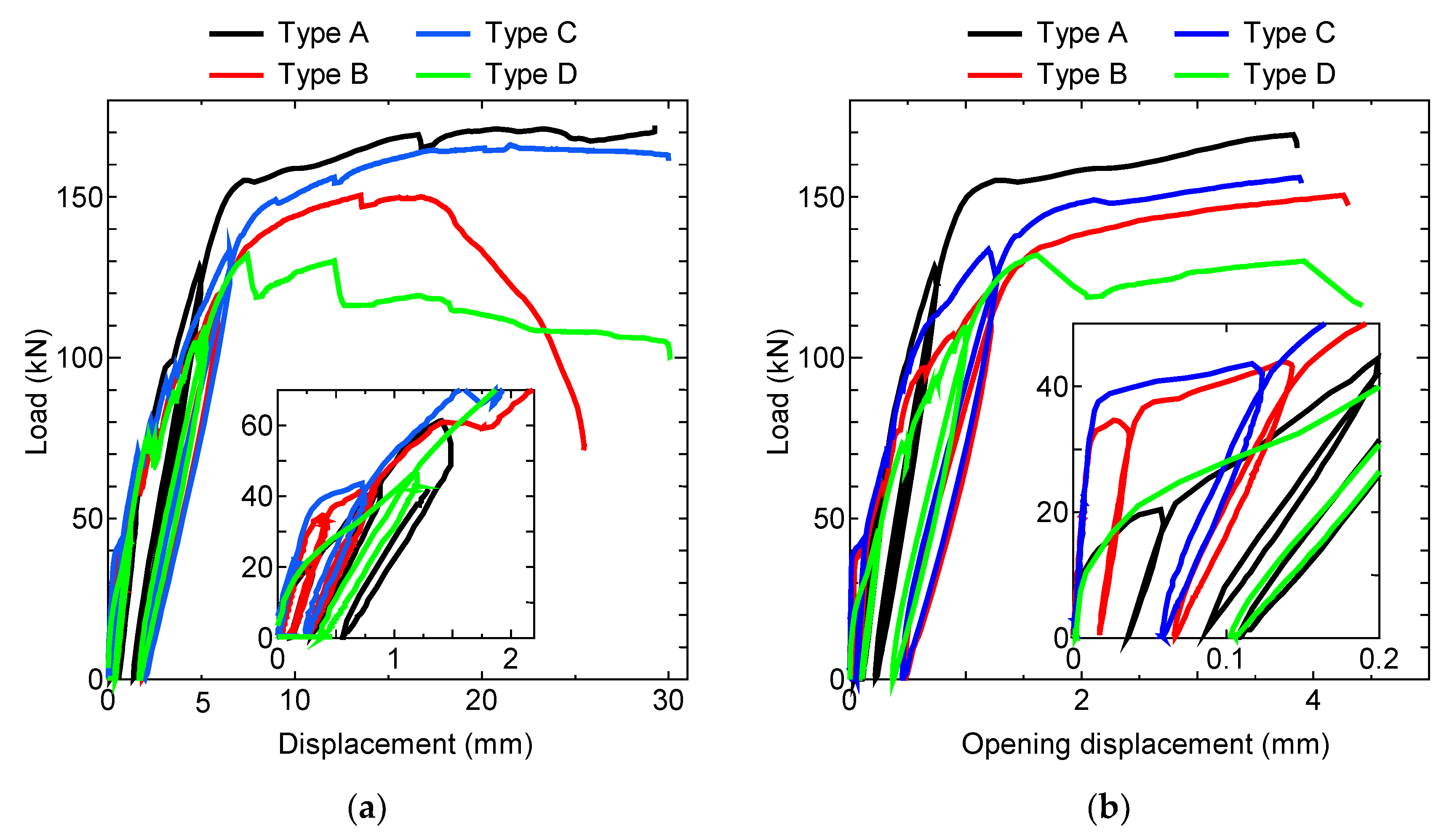
4.1. Load-Deflection Relationship

Figure 8a, where the specimens are presented in different colors, shows the relationship between the applied load and deflection at the span center. Figure 8a includes an enlarged figure of the initial loading stage up to 70 kN. As shown by the enlarged figure, the slope in the load-deflection curve of the Type A specimen began decreasing at around 10 kN due to the onset of the crack opening at the interface between the PCa concrete and the joint. This slope decreased significantly at around 155 kN when the strain of all longitudinal reinforcements reached the yield strain. Then, the load gradually increased with the deflection and reached the maximum value at 170 kN at the deflection of 25 mm.
In the Type B and C specimens, the initial slope of the load-deflection curve decreased at around 40 kN when the crack opening occurred at the interface between the PCa concrete and the joint. This load at the stiffness change was larger than that of the Type A specimen because the tensile bond strength between the PCa concrete and the polymer-based mortar was larger than that between the PCa concrete and plain concrete. Then, the load continued to increase until the strain of the longitudinal reinforcement reached its yield strength at around 130–140 kN, whereas the Type A specimen yielded at around 155 kN. This increase in the yield strength in the Type A specimen was due to the dowel effect of the transverse reinforcements inside the loop [24], but the Type B and Type C specimens did not have these reinforcements. From Figure 8a, the maximum load of the Type C specimen was 160 kN at the deflection of 23 mm, while that of the Type B specimen was 148 kN at the deflection of 17 mm. In addition, the decline in the load beyond the maximum load of the Type B specimen was more significant than that of the Type C specimen. These discrepancies were due to the differences in the overlapping lengths of the loop reinforcements; the overlapping length of the Type C specimen was 40 mm longer than that of the Type B specimen. Therefore, a larger overlapping length of loop reinforcements enabled the slab to exhibit a more ductile behavior under flexural loading beyond the maximum load because the large overlapping length increased the concrete area enclosed by the loops and the straight part of the loop reinforcements within the joint. Moreover, the load-deflection curve of the Type C specimen was similar to that of the conventional loop joint of the Type A specimen, and the two maximum loads were close. Thus, the Type C loop joint can be used instead of the conventional loop joint.
The initial slope of the load-deflection curve of the Type D specimen decreased at around 10 kN load, as was the case with the Type A specimen. Then, the load continued to increase with the deflection until the yield of the loop reinforcement around 110 kN. After reaching the maximum value of 130 kN, the load began to drop sharply at the displacement of 7 mm, showing the non-ductile behavior of the Type D specimen. This was because the Type D joint was narrow and did not have transverse reinforcements; therefore, there was insufficient restraint around the loop reinforcements to resist the tensile force in the transverse direction.

4.2. Opening at Interface between PCa Concrete and Joint

During the loading tests, the opening at the bottom of the interface between the PCa concrete and the joint of the specimens was measured by three Pi-shape gauges attached along each interface, as shown in Figure 5b,d. Each Pi-shape gauge could measure up to 5-mm opening displacement. Figure 8b shows the relationship between the load and the average opening displacement at the bottom of the interface. The figure includes an enlarged view of the initial stage of the load.
The crack opening at the interfaces of the Type B and C specimens occurred at loads of 36 and 38 kN, respectively, whereas that of the Type A and D specimens occurred at a load of 10 kN. This difference stemmed from the fact that the tensile bond strength of the PVA-FR mortar to the PCa concrete was larger than that of the concrete in the joint. Between the Type B and C specimens, which had different overlapping lengths of the loop reinforcements, the behaviors up to 90 kN were almost the same, but the crack widths differed beyond this load. The crack opening of the Type B specimen, which had a longer overlapping length, was smaller than that of the Type C specimen at the same load. The Type C and D specimens had the same overlapping length of the loop reinforcements but different joint materials. The load of the Type D specimen, which had concrete in the joint, began to drop from 130 kN, whereas the load of the Type C specimen, which had PVA-FR mortar in the joint, gradually increased with the opening displacement. Furthermore, the load-opening displacement relationship (Figure 8b) was similar to the load-deflection relationship (Figure 8a). Thus, the crack opening at the bottom of the interface between the PCa concrete and the joint affected the deflection of the specimen under flexural loading.

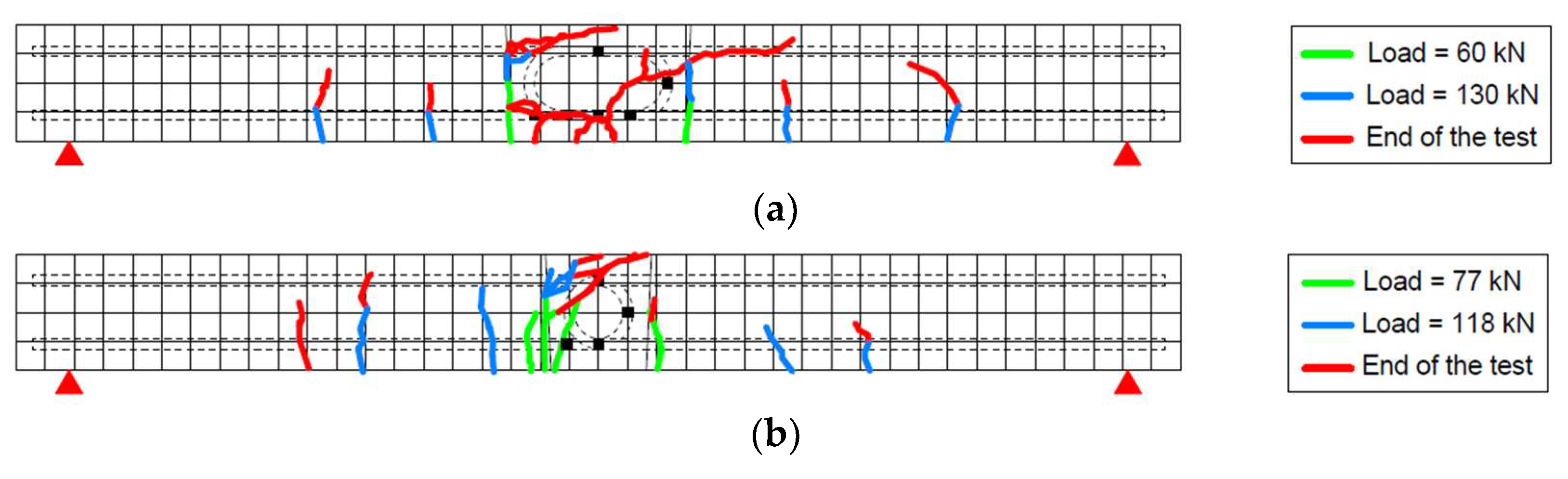
4.3. Crack Distributions of Specimens

Figure 9 presents a picture of the Type B specimen after the end of the flexural bending test as an example. This picture shows the North side and the bottom of the specimen. A large opening occurred at the interface of the PCa slab and joint and propagated from the bottom to the side of the specimen.
Figure 10 shows the crack distributions on both sides of each slab surface; the mesh size was 55 mm. The black squares indicate the position of the strain gauges attached to the loop reinforcements in the joint. When load dropping or yielding of steel bars was observed during the test, the loading was held to observe the cracking condition. Figure 10 presents the crack progress in three loading stages, namely, flexural cracking, longitudinal reinforcement yielding, and the end of the test, with different colors, namely, green, blue, and red, respectively. Flexural cracking is the stage where crack opening was observed at the joint interface.
Overall, in all specimens, the cracks at the joint interface occurred first. These cracks propagated, and new flexural cracks appeared on the PCa slabs with increasing load. In the Type A and C specimens, major cracks were observed at the joint interface, whereas more cracks were observed in the PCa slabs in the Type B and D specimens in addition to the cracks at the joint interface. These observations suggest that the Type A and C specimens had a higher bending stiffness at the joint than did the Type B and D specimens. A comparison of the Type C and D specimens around 70 kN shows that the Type C specimen had cracks at the joint interfaces only, whereas the Type D specimen had several cracks in the PCa slabs as well. Therefore, the use of PVA-FR mortar in the joint could reduce the crack occurrence in the PCa slabs up to the crack loading. At the end of the test in the Type C specimen, several cracks were distributed in the PCa slabs because the joint worked adequately and the stresses were transferred to the PCa slabs.

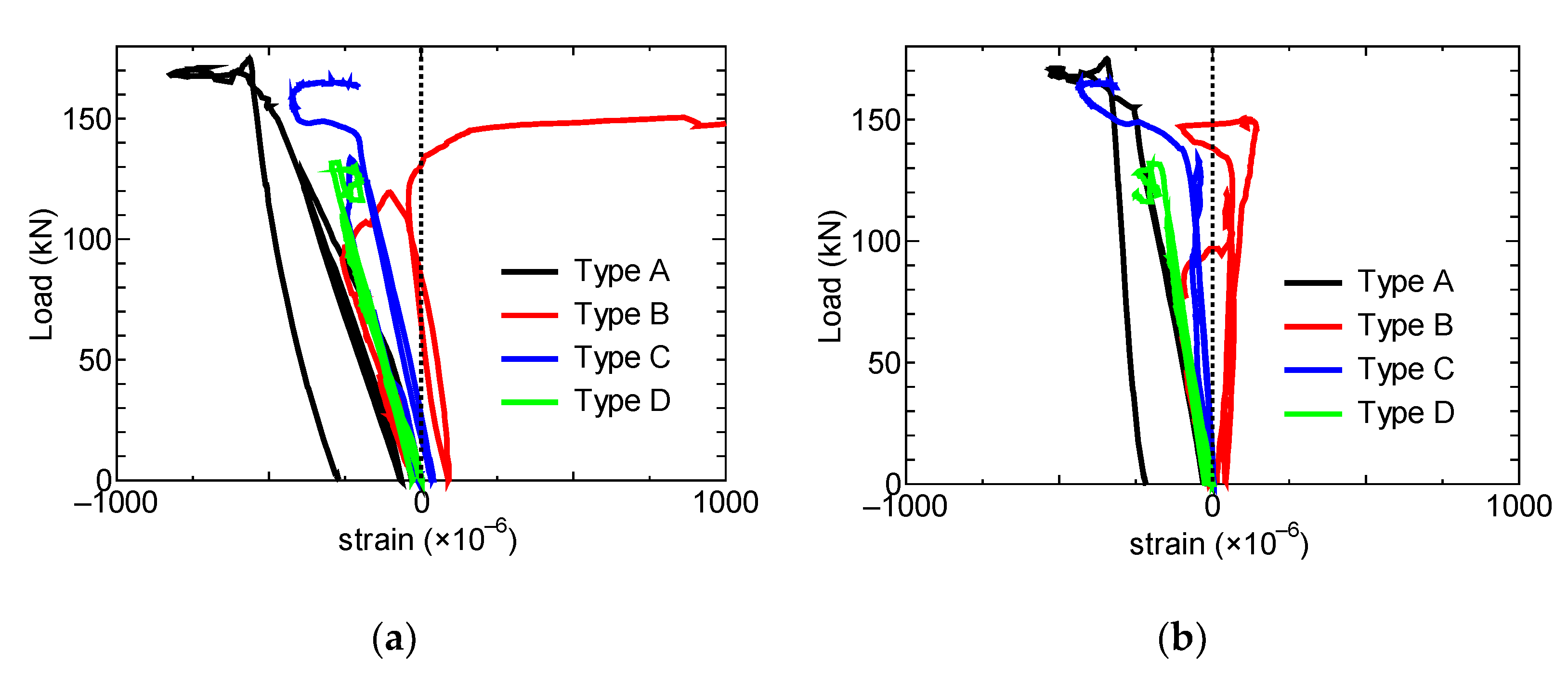
4.4. Strain Behavior of Reinforcement and Joint Casting Materials

4.4.1. Load-Strain Relationship of Reinforcement

As shown in Figure 5c, strain gauges to the loop reinforcement were attached to the middle position of the loop curve, at the top and bottom reinforcement located at the span center, and to the straight part of the tension-side reinforcement at intervals of 60 mm within the joint. Figure 11 presents the relationship between the applied load and the reinforcement strain of each measurement for the specimen Types A–D. The vertical axes represent the applied load, and the horizontal axes denote the strain. Figure 11 also shows enlarged views (insets) of the initial stage of the loading up to 50 kN. The reinforcement strain is the average value of the two loop reinforcements at each pair of locations. The insets of Figure 11 for all the test specimens show a small strain on both the compressive and tensile sides until the opening of the interface between the PCa slab and the joint. After the opening started at the interface, the strain of the reinforcement on the tensile side increased with the load. As for the reinforcement strain L1 (compressive side), the compressive strain occurred in the initial stage of the loading, but the strain gradually increased to the tensile strain as the load increased. The behavior of the reinforcement strain L2 (middle of the loop curve) was similar to that of L1.
In addition, from Figure 11a, the reinforcement strains L3 and L6 of the Type A specimen increased sharply at around 150 kN due to the yielding of the loop reinforcement. The reinforcement strains L1 and L2 (top and middle positions, respectively) also increased sharply to the tensile strain at around the same load. These increases were due to the increase in the bearing pressure in the loop reinforcement. The slope of the curve at the reinforcement strain L3 was lower in the specimen Types B–D than in the Type A specimen. Larger strain occurred in the specimen Types B to D than in the Type A specimen at the same applied load. The reason was that the bearing pressure in the loop reinforcement of the specimen Types B–D was larger than that of the Type A specimen, as the conventional loop joint (Type A) had a wider joint and longer overlapping of the loop. Similarly, as seen in the result of the reinforcement strain L3 of the specimen Types B and C, the bearing pressure in the Type B loop was larger than that in the Type C specimen because of the shorter overlapping of the loop in the Type B specimen. Moreover, the slope of the curve at the reinforcement strain L3 was lower in the Type D specimen (concrete joint) than in the Type B specimen (PVA-FR mortar joint). Hence, the bearing pressure in the Type D loop was larger than that in the Type B loop. The fiber reinforcement reduced the bearing pressure in the loop reinforcement by resisting the tension stress in the transverse direction—the cross-linking effect of the fiber reinforcement.
Figure 12 shows the relationship between the load and the transverse reinforcement strain of the conventional loop joint (Type A). The transverse reinforcement strain was measured in three reinforcements, as shown in Figure 5e1,e2 by attaching two gauges at each location. Almost no strain was observed in the transverse reinforcement until 150 kN, but the strain increased from around 150 kN at all measurement locations. In the load-deflection relationship (Figure 8a), the slope of the curve of the Type A specimen decreased from 150 kN, and the tensile strain in the loop reinforcement (Figure 11a) also increased from 150 kN. The largest strains occurred in the middle transverse reinforcement because of the bearing pressure from loop reinforcements, as shown in Figure 12b. This bearing pressure induced tensile stress in the transverse direction as tensile strains occurred from 150 kN in FM-1 and BM-1 that were close to the sides of the specimen, whereas compression strains occurred in FM-2 and BM-2 since the tensile stress was constrained by the adjacent loop reinforcements. Similar strain behaviors were observed in the top and bottom transverse reinforcements as shown in Figure 12a,c, respectively. Note that none of the transverse reinforcements reached the yielding, so the total of six D19 reinforcements was enough for the transverse reinforcement in the conventional loop joint.

4.4.2. Load-Concrete or Mortar Strain Relationship of Joint

Figure 13 shows the relationship between the load and the concrete or the PVA-FR mortar strain on the side surface of the joint. The location of the measured strain is presented in Figure 5d, and the strain was measured on both sides of the test specimens. The strain results in Figure 13 are the average of the strains on both sides at the same height.
Figure 13 shows similar behaviors between the Type A and C specimens on the side of the joint in terms of the compressive strain at C1 to C3 and tensile strain at C4; these behaviors are similar to those of RC slabs. In the Type B specimen (Figure 13a–c), the concrete strain transitioned from compression to tension at C1 to C3 at loads of 70, 100 kN and 130 kN, respectively, because of the diagonal crack propagation observed at the upper side of the joint shown in Figure 10b. The concrete strain at C4 in the Type B specimen initially showed tension strain, but it became compressive strain around 100 kN. This was because the crack opening at the bottom interface of the joint released the tension stress at C4. The strain behavior at C1 to C3 of the Type D specimen was in compression, as was the case with the Type A and C specimens, but the strain behavior at C4 was similar to that of the Type B specimen because of the crack opening at the bottom interface of the joint.

5. Conclusions

This study proposes a narrow, cost-effective loop joint that has a 200 mm width, D19 loop reinforcements, and no transverse reinforcements along with PVA-FR mortar. Material tests were conducted to select the fiber-reinforced mortar suitable for the proposed joint. A series of flexural loading tests for three slab specimens were conducted to investigate the flexural behavior of the proposed loop joint with the selected joint material (PVA fibers). The findings obtained from this study are summarized below.
  • The proposed polymer-based mortar exhibited excellent thixotropy and had PVA fibers, which have higher split tensile strength than PP fibers. There was almost no significant difference in compressive strength and static elastic modulus between the two fibers.
  • The performance of the proposed loop joint, which has a width of 200 mm and consists of PVA-FR mortar as joint casting material, was almost equivalent to that of the conventional loop joint (350 mm width) under a flexural bending moment.
  • The crack opening resistance at the interface between the PCa concrete and the joint in the proposed joint was larger than that in the conventional joint, since the bond stress of the PVA-FR mortar was larger than that of the plain concrete.
  • The use of PVA-FR mortar in the joint could reduce the crack occurrence in the PCa slabs up to the crack loading compared with the use of plain concrete in the joint.
  • A crack opening at the bottom of the interface between the PCa concrete and the joint increased the deflection of the slab under flexural loading.
  • A larger overlapping length of the loop reinforcements enabled the slab to have a more ductile behavior under flexural loading beyond the maximum load.
Within the scope of this study, the proposed joint has not undergone testing regarding its performance under fatigue. However, this is an important issue for applying the joint to real bridges [9,11,21]. Tests to investigate the fatigue performance of the joint need to be conducted in future studies.

Author Contributions

Conceptualization, S.F., M.H.N., H.F., H.M. and H.T.; methodology, S.F., M.H.N. and H.T.; investigation, S.F., M.H.N., H.F. and S.B.; resources, S.B. and H.M.; writing—original draft preparation, S.F. and S.B.; writing—review and editing, S.F. and M.H.N. All authors have read and agreed to the published version of the manuscript.

Funding

This research received no external funding.

Institutional Review Board Statement

Not applicable.

Informed Consent Statement

Not applicable.

Data Availability Statement

The data used to support the findings of this study are available from the corresponding author upon request.

Conflicts of Interest

The authors declare no conflict of interest.

References

  1. Fathalla, E.; Tanaka, Y.; Maekawa, K.; Sakurai, A. Quantitative Deterioration Assessment of Road Bridge Decks Based on Site Inspected Cracks. Appl. Sci. 2018, 8, 1197. [Google Scholar] [CrossRef] [Green Version]
  2. Sakai, H. Study on Renewal Method form Deteriorative RC Slab to Precast PC Slab in the Steel Girder Bridge. High Tech Concr. Where Technol. Eng. Meet 2018, 2169–2176. [Google Scholar] [CrossRef]
  3. Morcous, J.; Jaber, F.; Volz, J. A New Precast Deck System for Accelerated Bridge Construction. In Advancements in Geotechnical Engineering; Springer: Berlin/Heidelberg, Germany, 2017; pp. 229–241. [Google Scholar]
  4. Ma, H.; Shi, X.; Zhang, Y. Long-Term Behaviour of Precast Concrete Deck Using Longitudinal Prestressed Tendons in Composite I-Girder Bridges. Appl. Sci. 2018, 8, 2598. [Google Scholar] [CrossRef]
  5. Nippon Expressway Research Institute. Expressway Standard Technical Specifications by NEXCO, Outline of Bridge Specifications; Nippon Expressway Research Institute: Tokyo, Japan, 2017. (In Japanese) [Google Scholar]
  6. Ong, K.C.G.; Hao, J.B.; Paramasivam, P. A strut-and-tie model for ultimate loads of precast concrete joints with loop connections in tension. Cons. Build. Mater. 2006, 20, 169–176. [Google Scholar] [CrossRef]
  7. Ong, K.C.G.; Hao, J.B.; Paramasivam, P. Flexural behavior of precast joints with horizontal loop connections. ACI Struct. J. 2006, 103, 664–671. [Google Scholar]
  8. Henrik, B.J.; Linh, C.H. Tests and limit analysis of loop connections between precast concrete elements loaded in tension. Eng. Struct. 2013, 52, 558–569. [Google Scholar]
  9. Fédération Internationale du Béton. Structural Connections for Precast Concrete Buildings: Guide to Good Practice; International Federation for Structural Concrete (fib): Lausanne, Switzerland, 2008. [Google Scholar]
  10. DIN 1045. Plain, Reinforced and Prestressed Concrete Structures—Part 1: Design and Construction; DIN: Berlin, Germany, 2008. [Google Scholar]
  11. Ryu, H.K.; Kim, Y.J.; Chang, S.P. Experimental study on static and fatigue strength of loop joints. Eng. Struct. 2007, 29, 145–162. [Google Scholar] [CrossRef]
  12. Abe, H.; Hara, K.; Sawada, H.; Nakamura, M. Experimental study on precast PC slabs with a new joint system. Proc. JCI 2007, 29, 493–498. (In Japanese) [Google Scholar]
  13. Jean, P.V.; Robert, L.V.; Andrew, J. Flexural behaviour of headed bar connections between precast concrete panels. Cons. Build. Mater. 2017, 154, 236–250. [Google Scholar]
  14. Jean, P.V.; Robert, L.V.; Raj, K. Headed Bar Connections Between Precast Concrete Elements: Design Recommendations and Practical Applications. Structures 2018, 15, 162–173. [Google Scholar]
  15. Cheung, A.K.F.; Leung, C.K.Y. Effective jointing of Pre-cast concrete slabs with self-compacting HSFRCC. J. Adv. Conc. Technol. 2011, 9, 41–49. [Google Scholar] [CrossRef] [Green Version]
  16. Sasaki, K.; Nomura, T.; Oba, N.; Iwaki, T.; Tominaga, T. Experimental Study on Precast Deck Connection: Slim Fastener. Obayashi Tech. Res. Ins. Rep. 2018, 82, 1–8. (In Japanese) [Google Scholar]
  17. Nguyen, M.H.; Nakajima, A.; Fujikura, S.; Murayama, T.; Mori, M. Shear behaviour of a perfobond strip with steel fiber-reinforced mortar in a condition without surrounding reinforcements. Mater. Struct. 2020, 53, 45–59. [Google Scholar]
  18. Nguyen, M.H.; Nakajima, A.; Fujiwara, S.; Obata, R.; Fujikura, S.; Hirano, Y. Bending test of joint structure of precast PCa slab using perfobond strip and its corresponding element test. In Proceedings of the 5th World Congress on Civil, Structural, and Environmental Engineering (CSEE 20), Rome, Italy, 7–9 April 2019. (In Japanese). [Google Scholar]
  19. Reza, B.; Milad, A.; Ahmad, F. Mechanical properties of steel and polymer fiber reinforced concrete. J. Mech. Behav. Mater. 2019, 28, 119–134. [Google Scholar]
  20. Anandan, S.; Alsubih, M. Mechanical Strength Characterization of Plastic Fiber Reinforced Cement Concrete Composites. Appl. Sci. 2021, 11, 852. [Google Scholar] [CrossRef]
  21. Stephen, S.J.; Gettu, R. Fatigue fracture of fiber reinforced concrete in flexure. Mater. Struct. 2020, 53, 56–66. [Google Scholar] [CrossRef]
  22. González, D.C.; Moradillo, R.; Mínguez, J.; Martínez, J.A.; Vicente, M.A. Postcracking residual strengths of fiber-reinforced high-performance concrete after cyclic loading. Struct. Conc. 2018, 19, 340–351. [Google Scholar] [CrossRef]
  23. Balouch, S.U.; Forth, J.P.; Granju, J.-L. Surface corrosion of steel fibre reinforced concrete. Cem. Conc. Res. 2010, 40, 410–414. [Google Scholar] [CrossRef]
  24. Nakamura, H.; Mihashi, H. Fundamental Study on Flexural and Compressive Behaviors of Short Fiber Reinforced Mortar. Proc. JCI 1999, 21, 253–258. (In Japanese) [Google Scholar]
  25. Garcia, S.; Naaman, A.E.; Pera, J. Experimental investigation on the potential use of poly (vinyl alcohol) short fibers in fiber-reinforced cement-based composites. Mater. Struct. 1997, 30, 43–52. [Google Scholar] [CrossRef]
  26. Han, T.Y.; Lin, W.T.; Cheng, A.; Huang, R.; Huang, C.C. Influence of polyolefin fibers on the engineering properties of cement-based composites containing silica fume. Mater. Des. 2012, 37, 569–576. [Google Scholar] [CrossRef]
  27. Enfedaque, A.; Alberti, M.G.; Gálvez, J.C.; Beltrán, M. Constitutive relationship of polyolefin fibre-reinforced concrete: Experimental and numerical approaches to tensile and flexural behaviour. Fatigue Fract. Eng. Mater. Struct. 2018, 41, 358–373. [Google Scholar] [CrossRef]
  28. Fujiwara, H.; Maruoka, M.; Kawato, T.; Sugawara, T.; Yoshikawa, K.; Abe, T.; Takemoto, S.; Kasahara, H. Development of new types of repair materials by imparting thixotropic properties. Proc. Conc. Solut. 2016, 199–206. [Google Scholar]
  29. Kuraray Co., Ltd. Reinforcement of Mortar and Concrete, Suppression of Cracks Vinylon Fiber (PVA Fiber: Polyvinyl Alcohol Fiber). Available online: http://www.kuraray.co.jp/pvaf/pro_07.html (accessed on 30 July 2021).
  30. BarChip Inc. Reinforcing Polyolefin for Portland Cement Concrete. Available online: https://www.barchip.co.jp/business/ (accessed on 30 July 2021).
  31. Japanese Industrial Standards Committee. Polymer Short Fibers for Concrete and Mortar, JIS A 6208; Japanese Industrial Standards Committee: Tokyo, Japan, 2018. (In Japanese)
  32. Japanese Industrial Standards Committee. Method of Test for Compressive Strength of Concrete, JIS A 1108; Japanese Industrial Standards Committee: Tokyo, Japan, 2018. (In Japanese)
  33. Japanese Industrial Standards Committee. Method of Test for Splitting Tensile Strength of Concrete, JIS A 1113; Japanese Industrial Standards Committee: Tokyo, Japan, 2018. (In Japanese)
  34. Japanese Industrial Standards Committee. Method of Test for Static Modulus of Elasticity of Concrete, JIS A 1149; Japanese Industrial Standards Committee: Tokyo, Japan, 2017. (In Japanese)
  35. Leonhardt, F.; Menich, E. Leonhardt Concrete Course 3: Design of Reinforced Concrete; Kajima Institute Publishing: Tokyo, Japan, 1985; pp. 38–47. (In Japanese) [Google Scholar]
  36. Japanese Industrial Standards Committee. Steel Bars for Concrete Reinforcement, JIS G 3112; Japanese Industrial Standards Committee: Tokyo, Japan, 2010. (In Japanese)
Figure 1. A loop joint connecting two precast concrete slabs: (a) conventional loop joint; (b) proposed narrow loop joint without transverse reinforcements.
Applsci 11 08235 g001
Figure 2. Force transfer of loop joint.
Applsci 11 08235 g002
Figure 3. Fibers used for material tests: (a) PVA fibers; (b) PP fibers.
Applsci 11 08235 g003
Figure 4. Material test results: (a) test piece after split test and material test results of fiber-reinforced mortar: (b) compressive strength; (c) split tensile strength; (d) modulus of elasticity.
Applsci 11 08235 g004
Figure 5. Test setup and specimen details: (a) side view; (b) plan view: from bottom of specimen and reinforcements whose strains were measured (red: loop reinforcements, yellow: transverse reinforcements and Pi-shape gauge locations; (c) strain gauge locations of loop reinforcements; (d) concrete gauge locations; (e1,e2) strain gauge locations of transverse reinforcements in Type A loop joint.
Applsci 11 08235 g005
Figure 6. Joints before casting joint materials: (a) Type A; (b) Type B.
Applsci 11 08235 g006
Figure 7. Setup for flexural loading test (Type A).
Applsci 11 08235 g007
Figure 8. (a) Relationship between applied load and deflection at span center; (b) relationship between applied load and average crack width at bottom of interface between PCa concrete and joint.
Applsci 11 08235 g008
Figure 9. Type B specimen at end of bending test (North side).
Applsci 11 08235 g009
Figure 10. Crack distributions on South side of specimens (a) Type A; (b) Type B; (c) Type C; (d) Type D.
Applsci 11 08235 g010aApplsci 11 08235 g010b
Figure 11. Relationship between applied load and strain of loop reinforcement in joint (a) Type A; (b) Type B; (c) Type C; (d) Type D (locations of L1 to L6 in Figure 5c).
Applsci 11 08235 g011aApplsci 11 08235 g011b
Figure 12. Relationship between applied load and strain of transverse reinforcements of Type-A: (a) Top series; (b) Middle series; (c) Bottom series (locations of measured strains in Figure 5e1,e2).
Applsci 11 08235 g012
Figure 13. Relationship between applied load and strain of joint material at span center (a) C1; (b) C2; (c) C3; (d) C4 (locations of C1 to C4 in Figure 5d).
Applsci 11 08235 g013aApplsci 11 08235 g013b
Table 1. Mechanical properties of polymer-based mortar without fibers [28].
Mortar SlumpCompressive StrengthBond StrengthStatic ModulusLength Change
(mm)(MPa)(MPa)(GPa)(mm)
3 days7 days28 days 28 days28 days
6551.566.277.32.4933.9−250 × 10−6
Table 2. Mechanical properties of PVA fiber and PP fiber [29,30].
Fiber TypeDiameterLengthTensile StrengthElastic ModulusDensity
(mm)(mm)(MPa)(GPa)(g/cm3)
PVA0.6630900231.3
PP0.73050080.91
Table 3. Specifications of flexural loading test specimens.
Specimen NameJoint MaterialTransverse ReinforcementJoint Width (mm)Overlapping Width of the Loop Reinforcements (mm)
Type AConcreteAdded350280
Type BPVA-FR mortarNone200130
Type CPVA-FR mortarNone200170
Type DConcreteNone200170
Table 4. Material test results for flexural loading test specimens.
Specimen NamePCa ConcreteJoint MaterialMain and Transverse Reinforcements
f c E c f c j f t j f b j E c j f y s f t s ( D 13 ) f t s ( D 19 )
Type A70.040.667.74.914.940.6404524551
Type B68.841.964.97.377.033.2
Type C72.341.364.97.377.033.2
Type D69.039.467.74.914.940.6
Note: f c : compressive strength of PCa concrete (N/mm2); E c : modulus of elasticity of PCa concrete (kN/mm2); f c j : compressive strength of joint material (N/mm2); f t j : tensile strength of joint material (N/mm2); f b j : flexural strength by 100 × 100 × 400 mm test pieces of joint material (N/mm2); E c j : modulus of elasticity of joint material (kN/mm2); f y s : yield strength of loop and transverse reinforcements; f t s : tensile strength of loop and transverse reinforcements.
Publisher’s Note: MDPI stays neutral with regard to jurisdictional claims in published maps and institutional affiliations.

