
Applications of Cement-Based Smart Composites to Civil Structural Health Monitoring: A Review


1
Construction Technologies Institute (ITC)—Secondary Branch of Naples, National Research Council of Italy (CNR), c/o Polo Tecnologico di San Giovanni a Teduccio, 80146 Naples, Italy
2
Department of Engineering, University of Naples “Parthenope”, Centro Direzionale—Isola C4, 80143 Naples, Italy
*
Author to whom correspondence should be addressed.
Appl. Sci. 2021, 11(18), 8530; https://0-doi-org.brum.beds.ac.uk/10.3390/app11188530
Submission received: 10 August 2021
/
Revised: 10 September 2021
/
Accepted: 11 September 2021
/
Published: 14 September 2021
(This article belongs to the Special Issue Nanotechnology in Cement-Based Construction: Trends and Challenges)
Abstract
:In recent years, cement-based smart composites (CSCs) doped with conductive filler have attracted increasing research interest because of their high potentiality as self-sensing materials for civil Structural Health Monitoring (SHM) applications. Nevertheless, several issues are still open and need further studies. This paper presents an extensive state-of-the-art in which investigations on CSCs are summarized and critically revised, with the primary aim of outlining the main limits and development points. The literature review first addresses in detail several specific issues related to fabrication and operation as sensing elements of CSC samples. State-of-the-art applications of CSCs to SHM of reduced-, medium- and full-scale structural prototypes are extensively reviewed afterwards, resulting in a database useful to critically revise the main trends and open issues of the research in this field.
1. Introduction
Most infrastructures around the world are made of concrete, which represents one of the most used materials for human purposes, second only to water [1]. Despite continuous and significant advances both in technology and design of reinforced concrete (RC) structures, there is a large stock of existing structures and infrastructures that are experiencing deterioration phenomena or functional obsolescence [2,3]. As a matter of fact, in the last decades the effective management and maintenance of existing structures has become increasingly crucial in Europe and worldwide, and Structural Health Monitoring (SHM) has been recognized as a paramount tool in this concern. Indeed, SHM systems are aimed at automatically identifying damage occurrence on the monitored structure, evaluating also location, severity and potential consequences, by means of continuous in-situ non-destructive sensing and analysis of damage features characterizing the health state of a structure [4]. The timely detection of structural distress at very early stages has an impact on both safety and economic management [5]. Nevertheless, the desirable large-scale application of SHM technologies has been hindered by the combination of several limits, such as the large dimensions of civil structures and practical limits of traditional monitoring technologies. Accordingly, successful SHM systems applied to large infrastructures often need several conventional off-the-shelf sensors to ensure adequate spatial resolution of measurements, and they often cannot be easily integrated in the host structure [6,7].
Within this framework, the development of innovative integrated biomimetic SHM systems for civil structures based on the use of cement-based smart composites (CSC) has gained more and more attention in the last decades, also following the relevant progress in the field of nanomaterial synthesis [8]. Basically, CSCs exploit the piezoresistive effect induced by internally dispersed conductive fillers, namely the capacity of the electrical resistivity to change due to mechanical actions. Thus, by measuring the variation of electrical resistivity, strain can be monitored. Self-sensing materials for SHM allow capitalizing a series of potential benefits if compared to off-the-shelf sensors: high gauge factor, material compatibility, lower disturbance of the mechanical behavior of the hosting member, reduction of costs and complexity of installation because sensors can be embedded without varying the original design of the hosting member, limited probability of sensor failure [9,10]. From an economic point of view, in recent years there has been a significant reduction of filler fabrication costs whereby carbon-based nanomaterials are currently characterized by affordable unit costs (ranging from 10 $/g to 150 $/g depending on type, purity and dimensions); taking into account the very low filler concentration (typically 1% by weight of cement) and the little volume usually characterizing CSC sensors, they can be fabricated in large amount at affordable cost nowadays. As a result of the previously mentioned advantages, CSCs are ideal candidates for the development of biomimetic SHM systems able to mimic structure and functions of the human nervous system by means of densely distributed CSC sensors which capture local strain signals continuously processed by a central unit (Figure 1). CSCs also find other relevant applications related to civil SHM, such as traffic detection [11] or weigh-in-motion [12]. However, these applications are out of the scope of the present study.
Since the first studies on the piezoresistive behavior of CSCs, which date back to the early Nineties [13], significant research efforts by many research groups from all over the world have focused on numerous different aspects in the development of self-sensing CSCs, mostly related to material optimization. On the contrary, the number of research studies focused on issues functional to the application of CSCs to structural monitoring of real structures or structural components is currently limited, even if those aspects are worthy of investigation. While few research studies are so far available in the literature about the application of CSCs to structural prototypes, particularly at full-scale, their comprehensive review is relevant to disclose the promising applicative perspectives of CSCs in civil SHM and to identify critical aspects to investigate further.
This review study first reports a detailed analysis of relevant aspects and recent trends related to CSCs as self-sensing materials (Section 2). Research studies focused on applications of CSCs to civil SHM are reviewed afterwards (Section 3). Finally, the outcomes of this extensive literature review are critically discussed (Section 4) in view of the identification of the main limits and development points towards CSC-based SHM applications to full scale structures.
2. Fabrication and Operational Issues
CSCs basically have a multi-phase nature. Macroscopically, two phases can be assumed, namely the cementitious matrix and the dispersed conductive filler. The cementitious matrix is characterized by electrical resistivity values ranging between 106 and 109 Ω∙cm, so it may be referred to as the non-conductive phase. Such component is often cement paste, sometimes mortar, rarely concrete. The conductive phase usually consists of materials such as steel fibers (SFs), carbon fibers (CFs), carbon nanotubes (CNTs), carbon black (CB) or less frequently other nanomaterials: they are either used alone (single-doping) or combined into hybrid solutions (multi-doping) to enhance performance [9]. SFs represent the early functional filler for cementitious matrix. Originally developed as reinforcement solution in order to enhance the tensile strength of the base material [14], the SF capacity of improving electrical conductivity of the matrix was recognized afterwards: since then, the strain-sensing attitude of SF-doped RC has been investigated [9,15]. Typical SFs are characterized by diameter (D) ranging between 0.025 to 0.6 mm and length (L) from 3 to 30 mm depending on the intended use [16,17]. Despite the good mechanical and electrical properties of SFs, the sensing capacity was strongly affected by corrosion, so the use of carbon-based materials for CSCs has been considered as an alternative. CFs are characterized by several excellent properties including high electrical conductivity and corrosion resistance, due to the huge carbon content (larger than 92%-weight) [18] and high aspect-ratio [19]. Typical dimensional ranges (min-max) of CFs are 7–18 × 10−6 mm (D) and 3–30 mm (L). CFs are currently available on the market at relatively low cost, and they represent the most studied functional filler in the literature [13,20,21,22]. On the other hand, CNTs have recently gained more and more popularity as functional filler for CSCs since they are characterized by better mechanical and conductive properties with respect to CFs [23,24,25]. Discovered by Iijima in 1991 [26], CNTs consist of carbon atoms bonded in a helical crystalline structure. Two different forms are available, namely single-wall (SWCNTs) and multi-wall (MWCNTs) carbon nanotubes, consisting of one cylindrical lattice of carbon atoms and multiple concentrically positioned helical lattices, respectively. SWCNTs have thickness of a single atom and diameter (D) ranging from 0.4 to 3 nm, whereas MWCNT diameter (D) ranges between 1.4 and 100 nm. CNTs are characterized by very high aspect ratio able to ensure high electrical conductivity. Nevertheless, the main obstacles to the wide application of CNTs in CSCs are the high dispersion complexity and the higher cost with respect to CFs [27]. Differently from fiber-shaped materials, CB is a powder composed of conductive particles able to reduce the electrical resistance and enhance the density of cementitious matrix, although with negligible capacity in improving tensile mechanical properties [28]. The lower cost and dispersion complexity make CB an attractive solution for CSCs even if the low aspect ratio implies less effectiveness in enhancing the electrical conductivity of the composite: as a result, CB is often used in hybrid mixings in combination with fibrous filler [29,30].
Actually, there is frequently a third component in CSCs, the dispersant agent. Indeed, the dispersion of micro- or nano-scale filler into the cementitious matrix is commonly recognized as a challenge, especially for those conductive phases characterized by high aspect ratio with considerable attractive area forces and high probability of agglomeration [31]. The typical dispersant materials are of two types, surfactant and admixtures, with the common aim of a more efficient and homogeneous dispersion of the conductive filler into the matrix; this typically yields a reduction of filler amount and costs of dispersion, as well as enhanced and stable mechanical and sensing performance of CSCs [32].
During the fabrication process of CSCs involving the above-mentioned components, several issues may affect their main mechanical and sensing performances. Critical aspects are, among the others, mix design, dispersion of functional filler, curing process, electrical system configuration, durability and environmental effects. A detailed and critical discussion, in view of civil SHM applications, on findings from the literature concerning such issues is reported in the following sections.
2.1. Mix Design
CSC mix design concerns the definition of the optimal proportions among the different components. First of all, an appropriate concentration of functional filler has to be defined, taking into account the percolation threshold [33]. If an insufficient amount of filler is used, no conductive network is created into the matrix microstructure, and negligible changes of conductivity can be measured. Adding filler while remaining under the percolation threshold, the electrical resistivity strongly decreases with respect to the original value (corresponding to the matrix alone). In fact, increasing the relative amount of filler yields shorter and shorter conductive paths until the percolation threshold is exceeded; after that, appreciable changes of resistivity are no more observed [20,34]. In the presence of fine aggregates within the matrix, double percolation has to be considered [29] involving both filler and cement paste percolations: with increasing sand/cement ratios, the filler percolation threshold considerably increases. It is worth noting that the piezoresistive behavior of CSCs does not depend only on the amount of filler, but also on its dispersion into the cementitious matrix. In fact, even in the presence of relatively low filler concentration, if the gap between two generic adjacent filler particles ranges between 1 nm and 10 nm, conduction occurs through the cementitious matrix because of the transition of electrons through particles immersed into an electrical field (tunnelling) [35]. The best sensing performance of CSC is therefore achieved for filler concentrations corresponding to the coexistence of both conditions (effective dispersion, and concentration lower than the percolation threshold), although filler type and aspect ratio considerably affect the quantification of the optimal filler amount: in fact, the longer the conductive elements, the lower the percolation threshold and the tunnelling effect. Typical values of filler concentrations reported in the literature are about 5% for CFs and SFs, 1% for CNTs, and 10% for CB [36].
The mix design of the matrix starts from the conventional proportion for the considered typology (cement paste, mortar or concrete). However, the introduction of functional filler as well as dispersant agent has to be properly accounted for since both components affect workability at fresh state along with rheology and mechanical properties [37]. The key parameter governing those aspects is the water-to-cement (w/c) ratio. Theoretically, higher w/c values improve workability and effectiveness of fillers dispersion within the matrix. On the other side, large w/c ratios affect the mechanical properties of CSCs. Due to the complexity of the involved phenomena, a trial-and-error approach is generally adopted in the literature to obtain the best mixing proportions for assumed components [38]. Typical w/c ratios are set within the range 0.4–0.6, depending on the effective mixing composition [39]. Another major parameter related to mix design of CSCs is the possible presence of aggregates, fine or coarse, and the amount with respect to cement. The addition of aggregates to the cement paste decreases the electrical conductivity of the matrix and such effect is proportional to the aggregate diameter; thus, the sensing capacity decreases as aggregate dimension increases. In addition, coarse aggregates provide detrimental effect on dispersion effectiveness and create obstacles to the conductive passage [40]. Nevertheless, if sand amount is properly defined, higher electrical conductivity can be obtained due to the reduction of voids in the matrix [16]. Similarly, some studies report the addition of fly ash and silica fume to minimize matrix porosity and enhance the sensing properties of CSCs [41]. Alternatively, or in addition to the mineral admixture, plasticizers can be introduced during the mixing process in order to ensure sufficient workability of the paste and preserve both mechanical and rheological behavior [42].
2.2. Dispersion
The filler dispersion is the most critical stage of the CSC fabrication since its effectiveness strongly affects both mechanical and sensing properties. This task is particularly challenging for several reasons. Indeed, due to the size of functional fillers (generally, micro- or nanoscale), such conductive particles, even if present in very low amount, are characterized by huge superficial areas and, therefore, high Van der Waals interaction forces among them develop [43]. Because also of their hydrophobic nature, carbon-based fillers tend to form agglomerations into the matrix microstructure, especially when conductive materials with high aspect-ratio are used and the mixing is characterized by considerable viscosity [44].
In order to solve problems related to functional filler dispersion into the cementitious matrix, different techniques have been proposed in the literature. Those methods can be classified into two main categories: mechanical dispersion and chemical dispersion. Mechanical methods include all the techniques aiming at the physical dispersion of fillers, such as mechanical stirring, ball milling and sonication (or ultrasonication) bath. Stirring is an ordinary step of mixing and it is enough for ordinary reinforcing fibers. However, in the case of nanomaterials its efficiency is limited since the separation among them is temporary, and when the stirring stops the particles tend to agglomerate again. Only shear stirring at high-speed proved to be effective to uniformly distribute nano-sized fillers, even if the integrity of long particles is not guaranteed with direct consequences on percolation threshold and conductivity capacity [45]. Ball milling uses the action of impacting grinding balls for breaking the inter-particle bond, avoiding agglomeration. Nevertheless, also this technique is not adequate for long particles [46]. Sonication and ultrasonication are based on the use of sound and ultrasound waves, respectively, to win the bond forces. They are currently considered the most effective among the mechanical dispersion techniques: this particularly applies to ultrasonication of carbon-based conductive materials. Typical ultrasonic frequency used for dispersion is 20–30 kHz, causing high energy cavitation of the liquid mixture with homogeneous dispersion, even if proper input control has to be ensured to avoid damage to filler particles. In the case of long conductive fibers, low power bath sonication is recommended with input power lower than 130 W [8]. Sonication time represents another key parameter, since insufficient time (below 1 h) prevents adequate filler dispersion; conversely, too long sonication (higher than 5 h) tends to break the particles and reduce conductivity [47].
Chemical methods enhance filler solubility by means of the modification of the particle external shell. Two possible surface modifications are reported in the literature: covalent and non-covalent. The first is characterized by the use of neat acids, often combined with high temperature mixing, leading to an oxidation reaction between oxygen and carbon atoms with subsequent bonding of negatively charged carboxylic groups to the CNT surface [48]. The electrostatic repulsion forces among those groups ensure separation and make possible the effective filler dispersion. However, neat acids may have significant detrimental consequences on the mechanical and electrical response of carbon fillers and, as a consequence, of CSCs [49]. Conversely, non-covalent methods use the absorption property of molecules without any consequence on the material structure. This is generally pursued by adding surfactants to the mixture [50]. The most frequently adopted surfactants are methylcellulose (MC), polycarboxylate-based (PC) superplasticizers, anionic sodium dodecyl benzene sulfonate (SDBS) and lignosulfonate (LS). Consistent and conclusive findings about the effectiveness of covalent and non-covalent dispersion methods are not available in the literature [51], also because of the influence of different types of fillers and mixing proportions on the results. It can be only argued that, if the mechanical properties of CSC are relevant with respect to the scope of the application, non-covalent methods are preferable although they do not ensure absolute best sensing performance. On the contrary, covalent methods potentially yield good piezoresistive response, if properly applied. It is also worth noting that, when the dosage of surfactant exceeds a certain limit, both mechanical and electrical properties of CSCs might be weakened due to the development of air bubbles in the mixture [52]; moreover, the long-term effect of surfactants on CSCs are not established, yet. Finally, several studies show that chemical or mechanical dispersion techniques are not able to ensure uniformly distributed fillers within CSC matrix when used alone; the combination of these two methods has been therefore recommended in recent years [53,54].
2.3. Mixing, Moulding and Curing
Depending on the morphology and nature of functional fillers, different mixing processes can be used: (i) the first admixing method, in which water is first mixed with surfactant and fillers, and cementitious material and aggregates (if present) are added afterwards; (ii) the synchronous admixing method, when all components are added to the mix one by one; (iii) the latter admixing method, when water-cement and filler-water-surfactant mixtures are separately prepared and mixed together afterwards [23]. Once the final admixture is obtained, it is molded in the desired shape and cured. Both these fabrication aspects are relevant, since they may affect the sensing capacity of the final CSC.
Molding has an influence on the pore structure of CSC. Generally, the CSC admixture is casted into the framework and then vibrated in order to increase compaction. Nevertheless, in some cases pressing or extrusion have been applied, too [55].
Curing regime and duration have an influence on the microstructure of CSCs since they determine the hydration process. Moist curing yields high strength CSCs due to the dense microstructure; however, larger resistivity values are also obtained with respect to air cured CSCs. Furthermore, moist cured CSCs tend to increase their resistivity over time [9]. Indeed, at early curing age, the matrix presents high porosity, and the resistivity is low due to ionic presence. Conversely, the longer the curing age, the higher the sensitivity, because the bond strength between filler and matrix increase [56,57]. While a few studies are available in the literature about the curing effect on sensing properties of CSCs, the definition of an appropriate curing age is definitely a critical and under-investigated aspect in the development of CSCs.
2.4. Electrical Configuration and Measurements
The CSC fabrication as self-sensing element includes the arrangement of electrodes according to the selected electrical measurement method. It is well known that CSC resistance mainly consists of the resistances of the composite material, of the electrodes (generally negligible), and of the contact between electrode and CSC material. Moreover, CSCs are characterized by the presence of positively and negatively charged ions which, under the externally applied voltage, move towards the opposite voltage, thus creating a polarization potential. If polarization occurs during resistivity measures, particularly under direct current (DC), the recorded resistivity values tend to increase with time, so that an appropriate correlation between change in resistivity and strain can hardly be defined. Alternatively, the execution of resistance measures by using alternate current (AC) is able to strongly reduce polarization effects although impedance analysis is required, thus making the interpretation of measurements less straightforward [20]. Therefore, the definition of the electrical configuration directly affects the CSC sensing performance. Basically, two or four electrodes can be installed on each CSC sample following the two-probe or four-probe method, respectively. With the four-probe method, four electrodes are placed on the same side of the CSC: the two external probes are used for current application whereas the others are used to measure the voltage. The two-probe method uses just two electrodes working as current as well as voltage terminals at the same time. The four-probe method is able to reduce the contact resistance improving the accuracy of measurements, unless the CSC element has very little dimensions. Nevertheless, such methodology is characterized by higher complexity with respect to the two-probe method [58].
The materials adopted for CSC electrodes are characterized by high conductivity and resistance to corrosion. Accordingly, copper or stainless steel are the most used; other metals, such as silver or galvanized steel, are also seldom applied [59]. Two different installation approaches are typically used, namely embedding or surface attachment; the first proved to be sounder and more reliable for SHM applications, as well as characterized by lower polarization, higher durability and limited contact resistance [60]. Due to capacitance effect, the electrical resistivity measured between two electrodes increases as the spacing among them increases until a limit value is reached beyond which a constant trend is kept. Thus, it is recommended to place the electrodes at high distance. Increasing the size of embedded electrodes is another option to reduce capacitance. Nevertheless, it is less preferable since the higher the embedded section of the electrode, the higher the material-electrode contact resistance which affects measurements [9].
An appropriate design of electrodes has to take into account also other characteristics of the electrical circuit, such as the current type. In this regard, both AC and DC current may be used for resistivity measurements. As previously mentioned, DC measures of resistivity are generally simple, but they are affected by a time-based drift. On the contrary, AC current might be preferable since it induces very low polarization in the CSC. However, the AC frequency has to be properly defined. A commonly adopted criterion consists in increasing the frequency until the measured electrical resistance remains constant independently from its value. Another critical limit of AC measurements for SHM applications is the difficulty in the simultaneous acquisition of data from multiple sections of a CSC sensors; this is also the case when different impedance measurement devices are adopted because of the interaction among the electrical signals. In order to overcome the limits of AC and DC systems, a new technique has been recently proposed [61], the so-called biphasic DC measurement approach. It is based on the evidence that the polarization of the CSC sensor depends on the direction of the current flow. Thus, continuous cyclic charges and discharges by reversing the applied current drop the polarization effect and enhance the stability of readings (measured in the charging phase) over time. Unfortunately, the biphasic DC method does not allow for simultaneous multi-channel record of multiple CSCs installed on a common hosting structure. A promising multichannel strain measurement technique has been therefore recently proposed in [62]. Finally, current intensity as well as voltage amplitude also have an influence on the measuring repeatability and sensitivity of CSCs, depending on matrix and filler typology [63], even if, so far, more research studies are necessary in this sense to reach a firm conclusion.
2.5. Environmental Effects and Durability
Environmental actions on civil structures due to temperature and moisture may affect the long-term sensing performance of the installed CSC elements. In general, due to hot expansion and cold contraction of the cementitious matrix, the spacing of functional fillers changes and the tunnelling effect is modified. As a result, the electrical resistivity tends to decrease with increasing temperature until a limit value is reached above which the water present into the micro-structure pores evaporates causing a sudden increase of the resistance [64]. On the other side, repeatability and stability of sensing measures change if the external temperature changes. Under temperature range between 0 °C and 40 °C, adequate results in terms of stability are obtained (with the best performance in the range 20–40 °C), whereas measures become less repeatable at higher temperature (above 60 °C) or below 0 °C [65]. Extreme climate conditions such as freeze and thaw cycles might cause phase transformation of water, between solid and liquid state, causing micro-cracks into the matrix and irreversible increase of resistivity combined with low repeatability [66]. Nevertheless, investigations about the sensing ability of CSCs at very high temperature (larger than 200 °C, representative of the temperatures in fire-damaged structures) are in progress and the first results have been recently published in the literature [67]. These studies might have significant impact on the applications of CSCs to civil SHM but further studies are needed to reach well-established results and firm conclusions.
Change of ambient humidity may yield modification of the CSC internal moisture content which affects the sensing performance. Since water is an electrical conductor, saturated CSCs are systematically characterized by resistivity considerably lower than the dried ones. In fact, as known, conductive paths within CSCs are mainly due to overlapping fillers conduction, tunnelling effect conduction and ionic conduction. Moisture content essentially affects the latter, which offers a contribution, although generally limited, to the piezoresistive response. Furthermore, the presence of pore water with ionic concentration causes severe polarization affecting the piezoresistive performance in terms of repeatability [68].
The influence of moisture depends on type and amount of conductive filler. CB particles can absorb water with a subsequent increase of the electrical resistivity [69]. Conversely, for CSCs doped with CFs and CNTs, the electrical resistivity decreases as internal moisture increases due to the larger ionic conduction [68]. When SFs are used as conductive filler, particular attention should be paid to corrosion effect, for which no studies are available in the literature. Regarding the relationship between moisture and filler amount, for concentration lower than the percolation threshold an increase in CSC conductivity can be observed when moisture increases, even if with a consequent reduction in sensitivity due to the disturbance effect of ionic conduction, whereas high presence of fillers reduces the influence of moisture on sensing performance [70]. The main actions aimed at internal moisture reduction are air-drying and oven-drying. The latter proved to be more effective, although oven temperature and drying time are key parameters that need for appropriate experimental evaluation. For CSCs with 0.1%-weight of CFs, 3 days at 95° C may be recommended [63].
3. Applications to SHM of Structural Prototypes
If fabrication process and operational performance of CSCs have been extensively investigated at the material scale, with a relatively large number of research studies available so far, the application of CSCs as sensing elements for SHM of concrete structures or structural components is fairly limited, especially in the case of large- or real-scale realizations. Therefore, starting from a thorough literature review, the main research studies on this topic have been collected, and relevant characteristics and findings from those studies are reported hereafter distinguishing the applications to reduced-scale members and to medium- and full-scale structural prototypes.
3.1. Reduced-Scale Members
The monitoring capacity of CSCs doped with carbon black (CBCSCs) when embedded in reduced-scale unreinforced concrete (UC) columns was investigated in [71]. CB in the amount of 15% by weight of cement was used as filler, with a w/c equal to 0.4. 30 × 40 × 50 mm3 CBCSC samples were equipped with four copper nets across the whole cross-section. Sensors were cured in moist room for 28 days and, subsequently, dried at 60 °C for 48 h and, finally, encapsulated with an epoxy layer providing waterproof protection. CBCSC sensors were tested under cyclic axial loading, showing a stable and reversible response for low loading levels, whereas, for high stress levels with respect to the compressive strength (i.e., 70%), measurements were unstable. Two groups of six reduced-scale UC columns of size 100 × 100 × 300 mm3 were built: they were characterized by different concrete strength class (equal to C40 and C80, respectively). Sand and coarse aggregate were added to the same cement matrix of sensors. For each group, three columns were equipped with sensors and the remaining were considered as reference case, aiming at investigating also the possible influence of the embedded sensors on the mechanical response. Cyclic axial loading was applied (up to 30% of theoretical column axial capacity), first; monotonic tests were performed afterwards up to failure (Figure 2). Measurements from traditional transducers and strain gauges were used as benchmark. The stability of CBCSC sensor measurements in the case of cyclic loading in elastic regime was confirmed. Conversely, under monotonic loading, the embedded sensors showed good strain sensing capacity in elastic regime, whereas measurements were not reliable beyond the elastic limit, probably due to increasing transverse deformation. Failures of sensors and columns were not simultaneous: this result points out that matching of strength between sensor and concrete matrix is crucial to guarantee efficiency of strain sensing measures. Such matching should consider the triaxial loading strength of CBCSCs.
Sensing performance of CBCSCs embedded in reduced-scale beams subjected to monotonic as well as cyclic axial compression and three-point bending loading was investigated in [72]. The choice of the CB filler was due to its reduced cost with respect to CNTs. Three CBCSC types different for CB concentrations were realized and, due to decreased flowability, higher w/c ratios were applied, ranging between 0.35 and 0.45. The first admixing method was adopted and the resulting composite was poured into 10 × 10 × 60 mm3 metal molds. Four copper meshes were inserted into each sensor. After a standard curing process, each piece was cut in the middle to obtain two 10 × 10 × 30 mm3 CBCSCs. 40 × 40 × 160 mm3 beams were realized with the same material. CSC specimens were directly inserted into the beams during the vibration process both in compression and tension zones, according to the configurations depicted in Figure 3. Before the execution of three-point bending tests, under monotonic and cyclic low-level regimes, three beams equipped with as many sensors as the different CB-concentrations considered in the study were subjected to pure cyclic compression with the aim of assessing their self-sensing capacity. Sensor with 2% CB exhibited the best fractional changes of resistivity (FCR) and monitoring sensitivity compared to those with 0.5% and 1% CB, even if repeatability of measures increased as CB content decreased and, at low stress values, the difference in FCR readings among the sensors were more limited. From the results of three-point bending tests, the Authors concluded that: (i) CBCS with 2% CB exhibited the best sensing performance; (ii) the embedded sensor close to the loading point presented the largest electrical resistivity changes because of the higher stress magnitude; (iii) sensors in the compression zones exhibited gradual decrease in electrical resistivity but they suddenly returned to their initial resistivity values when approaching the flexural failure, whereas the counterparts in the tension zones experienced an increase in electrical resistivity followed by an abrupt jump near the flexural failure.
Roopa and his co-authors [73] carried out experimental tests on reduced-scale beam and column; CSCs doped with different nanocomposite were embedded into those elements. Sensors were realized by using three different conducting filler types (MWCNTs, CFs, and G) combined with each other. Cement mortar matrix was used to ensure proper strength, and w/c ratio equal to 0.45 was assumed. Sensors had dimensions 50 × 50 × 20 mm3 and were equipped with two electrodes in the central part. Concerning mix-preparation, CFs were directly mixed with cement and sand in the dry state, whereas both G and MWCNTs were priorly sonicated with water. Electro-mechanical three-point flexural tests were performed first on sensor specimens, respectively with 0.25% and 0.50% of nanomaterials by weight of cement. Results showed that higher nanomaterial percentage (i.e., 0.50%) enhanced flexural strength and electric properties without signal fluctuation. Therefore, such sensor was embedded into the beam and the column, both of sizes 100 × 100 × 500 mm3. A three-point flexural test was conducted on the beam, and a uniaxial compression test was performed on the column. The recorded measurements in terms of load and electric resistance were characterized by trends very similar to the ones corresponding to the initial sensor testing, in spite of some observed anomalies requiring further development of sensors.
The combination of CNTs and CB as conductive fillers in CSC sensors embedded into reduced-scale columns under both monotonic and cyclic axial load tests was experimentally investigated in [74]. The reason of such combination lies in the easier dispersion without sonication with respect to CNTs alone. Fly ash was also added to the mixing. Sensors had dimensions 20 × 20 × 50 mm3 and stainless-steel gauzes were used as electrodes. Overall, twelve columns were casted, divided into two groups associated with different concrete strength (C30 and C50, respectively). Three columns for each group were equipped with a sensor placed at the center of the solid during pouring, whereas the remaining three columns were used as benchmark in order to evaluate the influence of the embedded sensor on the mechanical response of the concrete member. Cyclic loading within the elastic limit was applied first to both sensors and concrete columns; then monotonic tests were carried out up to failure.
Experimental results showed that: (i) sensors exhibited stable and repeatable measurements under cyclic and monotonic compression either they were embedded into concrete columns or not; (ii) the presence of sensors did not affect the mechanical response of the column; (iii) a difference was recorded between signals collected from embedded and not-embedded sensors, due to the different mechanical properties of concrete and sensors.
3.2. Medium and Full-Scale Members
RC beams strengthened by means of RC layers doped with CFs (CFRC) were tested under four-point bending by Wu and his co-authors [75] in order to investigate their viability as strengthening solution as well as monitoring system (see Figure 4). A total of eighteen 3000 mm long beams characterized by different location and thickness of strengthening layers were tested. These layers consisted of a mix of CFs (5% by weight of cement), cement, fine aggregate, coarse aggregate, and water. Steel reinforcement was wrapped by epoxy resin to prevent metallic conductivity, whereas four stirrups spaced at 200 mm in the central part of the beam were used as electrodes. CFRC layers were put on plain concrete during casting operations.
The electrical resistance measurements were made by means of the principle of Wheatstone bridge according to which the initial electrical resistance of the whole beam (included top and bottom layers connected in parallel) was first measured; known the resistance of the remaining bridge arms, the resistance of the beam depending on the applied load was derived. Hence, the presence of CFRC layers directly affected the electrical properties of the beams, decreasing the initial electrical resistance and yielding a larger increase of the electrical resistance at increasing layer thickness. Nevertheless, the adopted measuring method prevented a separate monitoring of top and bottom layers. Somehow consistent relationships between electrical resistance, loading, deflection/strain and cracks were observed only from a qualitative point of view. Furthermore, the construction technology seems quite complex and expensive to be applied at large scale.
A comparative analysis of the experimental results obtained from cyclic tests on three RC shear-critical columns was presented in [76]; two columns were doped with SFs and carbon nano-fibers (CNFs), respectively, whereas the remaining one was made of plain RC and used as benchmark case. Assessing if functional fillers enhanced structural performance and created self-sensing capacity were the objectives of the research. All the columns had low aspect-ratio. CNFs and SFs were introduced in the mixing at a dosage of 1% by volume, based on the results of an extensive number of trials. Wire meshes with soldered gauge copper wire were placed at four cross-sections (four-probe method), as shown in Figure 5. The experimental outcomes proved that the addition of SFs and CNFs to concrete improved the structural capacity of the column, but only SFs showed a potential as a solution for SHM, at least in the elastic field.
CSCs doped with CNFs and CFs have been applied to RC beams as strain and damage sensors in [77]. Cement paste was used as matrix for the sensors, with a fixed 0.5 w/c ratio. Five different dosages of conductive admixtures were prepared: one with 2% CNFs, two with 1% of different types of CFs, and the others with CFs subjected to an oxidation treatment. Mechanical stirring and sonication were applied for mixing and dispersion. Two different sizes of prismatic sensors were made, namely 20 × 20 × 80 mm3 (Type A) and 200 × 7 × 80 mm3 (Type B). The four electrical contacts consisted of strips of silver paint applied on the perimeter, to which four copper wires were wrapped. A total number of 28 sensors were installed on a RC beam of dimensions 200 × 300 × 3900 mm3; they were placed in the central part of the beam at different locations (Figure 6). Under the four-point bending scheme, all sensors were subjected to the same value of bending moment. Two different installation methods were applied: bonding by means of epoxy resin and direct casting. Both strain-sensing and damage-sensing cyclic tests were performed; they were respectively characterized by reduced maximum load and increasing loading up to failure. Experimental results showed that both CNFs and CFs were able to measure superficial strain, even if better sensing capacity was achieved by 2% CNF sensors. Furthermore, the thinner the sensor the better the performance, probably due to the large adhesion surface (wide as the RC beam) and to the reduced strain gradient along sensor depth. Finally, negligible effect of the installation method on the sensing capacity was observed.
The influence of loading rate on the sensing capacity of CSCs doped with CNFs was investigated by Witarto and his co-authors [78]. 25.4 mm wide cubic sensors, equipped with four copper mesh electrodes, were installed in critical regions of four full-scale RC columns designed to fail in shear. Specifically, sensors were electrically isolated with epoxy resin and fixed to stirrups involved in the shear-resisting mechanism by using plastic zip ties before concrete casting. Cyclic loading with increasing amplitude was applied at different rates for each column. Based on the experimental results, the Authors concluded that sensors performed reasonably well under a qualitative point of view, even if further studies would have been needed to establish a quantitative relationship between damage levels and measured electrical resistance variation.
In [79] the effect of micro-CFs on the strain sensing ability and structural capacity of RC beams in the absence of stirrups was experimentally investigated. Three beams with 125 × 350 × 1500 mm3 dimensions and characterized by different longitudinal reinforcement ratios were monotonically tested up to failure under four-point bending scheme. CFs were introduced in the concrete mix and this was poured at top and bottom surfaces of mid span sections for a length of 350 mm and a depth of 78 mm (Figure 7). Electrically conductive paint was applied on top and bottom surface of RC beam close to the point of application of the load. Copper wires were connected to the conductive paths via adhesive tape. Before loading, different initial electrical resistance values and gauge factors between compression and tension side were recorded, due to the presence of longitudinal reinforcement. However, this did not significantly affect the experimental results, yielding well correlated strain and electrical resistance variation both in tension and compression; specific equations obtained through regression analysis of measurements were proposed to evaluate the strain known the fractional change in electrical resistance, in order to continuously monitor the beam response.
The first experimental study focusing on the structural monitoring performance of CSCs doped with MWCNTs and embedded into RC beams subjected to static and dynamic excitations is reported in [53]. Cubic CSCs (with 5 cm edge) were prepared. Cement paste was doped with 1% MWCNTs by weight of cement and w/c ratio was 0.45. Filler dispersion was achieved by using dispersant and sonication. Resistivity measurements were performed by employing both two-probe and four-probe configurations in DC current and under controlled temperature. The electromechanical tests carried out on cubic sensors under both cyclical and dynamic compressive loads confirmed the strain sensitive properties of sensors. Furthermore, the response was almost constant with respect to frequency, although for some sensors a linear trend was observed. After CSC characterization, seven sensors were embedded at the top of a full-scale simply-supported RC beam subjected to both static bending loading (CSC under compression stress) and dynamic impulse loads (Figure 8). The experimental results demonstrated the effectiveness of sensors under static loads, while fairly accurate strain measurements were obtained at the very low strain levels associated with the applied dynamic loads; nevertheless, Power Spectral Densities (PSDs) computed by processing the dynamic signals from traditional strain gauges and CSC sensors confirmed that the latter were promising also for modal testing.
The same research group performed further experimental studies on the RC beam of Figure 8 with the aims of investigating the performance of CSCs in resolving the dynamic response of the beam [80] and of validating a multichannel strain measurement technique able to retrieve strain distribution along the member under static load [62].
In the first study [80] the electromechanical response of sensors was first assessed by means of cyclic load tests, aimed at calibrating relevant sensor parameters before embedment; vibration tests were conducted on the RC beam afterwards. This study remarks the importance of a specific calibration of the sensor before embedment into structural members. The results also showed that sensors were able to reveal impulsive loads and to provide dynamic strain measurements useful for modal identification of the beam. In order to evaluate the reliability of results, traditional transducers (piezoelectric accelerometers) were installed on the beam; results from embedded CSC sensors and piezoelectric accelerometers were in good agreement with each other, confirming the promising applicative perspectives of CSC sensors for SHM of full-scale concrete structures.
In [62] the RC beam was subjected to four point bending loading (with CSCs under compression) and, starting from each sensor output, the strain distribution along the structural member was derived. The comparison of the retrieved strain distribution with the results of a simplified analytical model revealed satisfactory sensing performance.
Rao and Sasmal [54] proposed an experimental study on CSCs aimed at assessing their potential for vibration-based SHM of large structures. MWCNTs were introduced into cement paste. Three different types of MWCNTs were considered: one non-functionalized pristine-MWCNT (P-MWCNT) and two chemically functionalized MWCNT, one by hydroxyl(–OH) group and the other by carboxyl acid (–COOH) group. SDBS was also used as dispersant. The adopted w/c ratio was equal to 0.4 for all the mixtures. A combination of chemical and physical methods in series were adopted for filler dispersion (i.e., dispersion in solvent followed by sonication). For each group of MWCNTs, four different dosages were considered: 0.10, 0.25, 0.50, 0.75 (%) by weight of cement. Three samples of size 50 × 50 × 50 mm3 for each MWCNT type were fabricated. Electrical conductivity as a function of MWCNT dosage was measured by means of preliminary electrical tests. Then, experimental tests under cyclic compression were performed on cubic sensors with maximum applied load equal to 25% of the capacity, showing that: (i) for CNT concentrations lower than 0.50% the change in electrical resistance was not reversible and stable; (ii) the sensitivity of COOH-MWCNT was higher than others due to the enhanced chemical bond between fillers and surrounding cement matrix, increasing the load transfer capacity; (iii) the relationship between FCR and strain was linear. The evaluation of the vibration sensing capacity of CSCs was conducted afterwards by exciting through an impulse hammer a RC full-scale beam, 4500 mm long and representative of an existing bridge girder, on which CSCs were installed on top surface at the mid-span by means of a mechanical anchor device (Figure 9).
The sensor was electrically isolated by means of two plastic sheets and the benchmark was given by three accelerometers placed at the bottom of the beam. From the results of the dynamic tests the following conclusions were drawn: (i) CNT concentration equal to 0.75% allows for detecting the first three vibration modes with high accuracy as confirmed by the off-the-shelf accelerometer sensors, whereas lower dosages were associated with insufficient conductive path inside the cement matrix; (ii) functionalization has great influence on dynamic strain measurements due to the enhanced bonding between CNTs and matrix, with COOH-MWCNTs showing the best results.
In ref. [81] the strain-sensing performance of a CSC sensor doped with CNT and embedded in a beam tested under three-point bending was investigated. The CSC sensor was made of water, cement and sand, with a w/c ratio equal to 1:3. MWCNTs were used as fillers in a concentration of 0.8% by weight of cement. Filler dispersion was performed according to the first admixing method, with SDBS as dispersant and sonication. A 52 × 52 × 150 mm3 sensor was embedded into a reinforced mortar beam (the components of the mix were the same as for CSC, with the only exception of CNTs) of dimensions 160 × 130 × 650 mm3. Eight corrugated steel bars were placed within the CSC (Figure 10) to enhance strain transfer between beam and sensor by means of a mechanical action in addition to the chemical (inter-material) bonding. The recorded sensing response revealed a non-linear trend since the elastic phase, probably due to the presence of the corrugated steel dowel affecting the load-transfer mechanism. However, the load-strain diagram showed a clear relationship between the changes of slope of the response curve and damage affecting the beam.
Relevant information from the previously described experimental studies related to both CSC sensors and their applications to structural prototypes are summarized in Table 1 and Table 2, respectively, in order to provide a synthetic but useful database, representing the current state-of-the-art about investigations of CSCs for civil SHM scopes, and for the identification of the main research trends and open issues.
4. Discussion and Open Issues
Significant properties of CSCs at the material scale have been presented in Section 2. Relevant outcomes of the experimental studies focused on the applications of CSCs as sensing elements for civil SHM applications have been reported in Section 3, resulting in the most up-to-date state-of-the-art on the topic. The most significant parameters of the collected studies are reported in Table 1 and Table 2 for the aspects related to fabrication and sensing, respectively. Those data are herein collectively analyzed, resulting in a critical discussion aimed at identifying the most promising research outlooks in the field of civil SHM based on CSCs.
4.1. Fabrication
Several dispersion procedures depending on the filler typology have been introduced. For CFs and SFs, as well as CB, mechanical stirring is generally applied. Conversely, if CNTs are used as conductive filler, sonication or ultrasonication are systematically carried out often coupled with the use of surfactant (LS or SBDS, in particular). Therefore, CNT-based CSCs are typically of limited dimensions, since the adoption of methods such as sonication or chemical reaction cannot be performed at large scale due to practical limits as well as economic reasons, whereas large scale CSCs can be obtained by using fiber-shaped filler. Acid functionalized fillers in CSCs have been also investigated by some Authors, showing high sensing performance. Hybrid solutions given by the combination of different filler types provide several benefits in terms of reduction of dispersion complexity; moreover, the use of additives, such as fly ash or silica fume, allows to reduce internal pores. Cement paste is typically used as a matrix due to the easier filler dispersion and lower concentration of conductive material with respect to mortar and concrete. The latter is adopted only if fiber-shaped filler is used. w/c ratio values range between 0.33 and 0.50, depending on filler type and additives.
Appropriate spacing of electrodes must be ensured in order to obtain accurate resistivity measurements. In this regard, a minimum value commonly assumed for the distance between two consecutive electrodes is 5 mm. About electrode material and installation, different options have been investigated (copper or steel, embedded or externally pasted) but negligible influence on CSCs performance has been reported. Less systematic studies focused on curing procedures have been found in the literature; most of them are based on laboratory or standard condition (i.e., with almost constant temperature and humidity). In a few cases, oven- or air-dry processes have been performed in order to improve the sensing performance by the elimination of the internal residual moist water; however, duration and imposed temperature value vary from case to case, and no firm conclusion on the effect of temperature or moisture is drawn for CSCs applied to structural prototypes. Nevertheless, a very recent study [62] highlighted the significant influence of hourly temperature variations on the electrical resistivity, whereas changes in moisture yielded only secondary effects.
4.2. Sensing Applications
The first studies on CSC applications for SHM of medium- and full-scale structural elements concerned RC members completely or partially doped with conductive fibers, specifically CFs and SFs [75,76]. These studies qualitatively confirmed the promising applicative perspectives of multifunctional CSCs for civil SHM. Nevertheless, the large costs and fabrication complexity make the corresponding functionalization approaches inconvenient for civil structures; as a result, an alternative approach has been pursued by installing small self-sensing CSC elements into RC members. This is also the only implementable solution in the case of existing structures, which are the main focus of SHM due to their obsolescence. Very different sensor dimensions have been adopted mainly depending on sensing application and filler typology. Specifically, volumetric ratios (the ratio between the volume of the CSC sensing element and that of the tested structural member) typically considered in the collected literature range between 5.1 × 10⁻⁵ and 5.2 × 10⁻². No information about the required number of sensors is reported with respect to reliability of measurements, redundancy of the SHM system, or SHM targets. Generally, CSC sensors are embedded close to the external edge of the member. Specifically, the sensor is placed within the framework before casting operations. A few studies consider different installation methods namely external attachment by means of highly adhesive resin [77] or mechanical connection by a steel device able to ensure structural continuity and electrical insulation of the CSC [54], or embedment with the addition of corrugated steel dowels to improve the strain transfer [81]. Nearly all methods yielded reliable measurements. However, embedding is the preferred solution due to the complete inclusion of CSC, which ensures good performance in terms of strain transfer from the monitored member. Conversely, the external installation appears more feasible for SHM of existing structures, even if embedment could be still carried out by perforation of the member and use of slightly expansive cement-based materials to restore the original continuity. In any case, further studies aimed at the evaluation of the influence of installation methods on the sensing performance of multifunctional CSCs are needed. CSCs are typically applied to measure monodirectional strain induced by externally applied loads. Specifically, pure axial- or bending-induced strain have been investigated, with sensors installed in constant-stress regions in the latter case; more complex stress states are still under-investigated. The sensing performance of CSCs as dynamic sensors have been very recently investigated at large-scale obtaining promising results. This opens interesting applicative perspectives for the application of CSCs to full-scale members. However, in view of SHM applications, some issues are still far from being overcome. For instance, repeatability and stability of measurements are significantly affected by the applied stress levels. Under cyclic excitation, indeed, stable data can be obtained until a maximum stress level of 30% of the strength of the material. Beyond that limit repeatability problems have been observed. Mechanical compatibility between CSCs and monitored RC members has been also recognized to play a critical role [71], especially when CSCs are used for monitoring high-stress levels close to failure. Unfortunately, very few studies report the mechanical properties of CSCs and the material of the structural prototype; thus, it is impossible to draw any firm conclusion. About the electrical configuration, the four-probe method is mostly adopted because of its accuracy, but a few studies provide information about current type (i.e., AC, DC and biphasic DC) and, in particular, quantitative parameters such as intensity and frequency for AC measurements. Finally, conventional wired data acquisition systems have been always adopted, so further investigations about applicability of wireless systems in combination with CSCs for civil SHM are of particular interest.
5. Concluding Remarks
CSCs are nowadays considered a very promising sensing solution for biomimetic SHM of civil structures due their piezoresistive capacity given by the presence of conductive fillers. Despite the great research efforts on this topic during the last decades and several studies available in the literature, real-case applications of CSCs to civil SHM are still limited due to a number of motivations outlined in the present paper. In particular, this review paper discussed well-established trends and open issues related to CSCs, with a special focus on applications to structural members for SHM purposes. Major aspects related to fabrication procedure and material characteristics were revised, first. Research studies dealing with the evaluation of the sensing performance of CSCs applied to structural prototypes have been collected afterwards, and an experimental database has been compiled to provide an immediate overview about the current state-of-the-art on this topic. The main outcomes of this work can be summarized as follows:
- Research studies focusing on the application of CSCs for SHM of full-scale structural RC members are still limited, and further investigations are required.
- Small CSC sensors are more effective than full-scale CSC elements for SHM applications due to reduced cost and installation complexity, higher accuracy of measurements, and potential to achieve dense distributions of sensors. Nevertheless, some relevant issues are still open, such as minimum number of sensors and influence of installation methodology on the sensing performance.
- For SHM applications to full-scale members at high-stress levels, the mechanical compatibility between the concrete of the hosting member and the cementitious matrix of sensors represents a critical issue, and therefore concrete matrix might be preferable for CSCs. However, the presence of aggregates introduces some critical points about filler dispersion and optimal concentration.
- So far, CSCs have been applied for monitoring pure or uncoupled loading conditions, to which, nonetheless, not all structural cases can be reported. Therefore, the sensing performance of CSCs in the presence of more complex stress states should be investigated. Furthermore, the promising sensing performance of CSCs as dynamic sensors requires more comprehensive verifications in order to establish relevant technical features (such as range of applicability and sensitivity), eventually taking into account different schemes or dynamic sources.
- Finally, significant issues such as ageing phenomena, durability, or data acquisition and data transmission solutions for SHM applications need to be extensively studied.
Author Contributions
Conceptualization, C.R.; investigation, P.C.; resources, P.C., C.R. and A.O.; formal analysis, P.C. and C.R.; methodology, C.R.; data curation, P.C.; writing—original draft preparation, P.C.; writing—review and editing, C.R. and A.O.; visualization, C.R.; validation, C.R.; supervision, C.R. and A.O.; project administration, C.R. and A.O. All authors have read and agreed to the published version of the manuscript.
Funding
This research received no external funding.
Institutional Review Board Statement
Not Applicable.
Informed Consent Statement
Not applicable.
Conflicts of Interest
The authors declare no conflict of interest. The funders had no role in the design of the study; in the collection, analyses, or interpretation of data; in the writing of the manuscript, or in the decision to publish the results.
References
- Wangler, T.; Roussel, N.; Bos, F.P.; Salet, T.A.; Flatt, R.J. Digital Concrete: A Review. Cem. Concr. Res. 2019, 123, 105780. [Google Scholar] [CrossRef]
- Enright, M.P.; Frangopol, D. Probabilistic analysis of resistance degradation of reinforced concrete bridge beams under corrosion. Eng. Struct. 1998, 20, 960–971. [Google Scholar] [CrossRef]
- Cassese, P.; De Risi, M.T.; Verderame, G.M. A modelling approach for existing shear-critical RC bridge piers with hollow rectangular cross section under lateral loads. Bull. Earthq. Eng. 2019, 17, 237–270. [Google Scholar] [CrossRef]
- Rainieri, C.; Magalhães, F.; Gargaro, D.; Fabbrocino, G.; Cunha, A. Predicting the variability of natural frequencies and its causes by Second-Order Blind Identification. Struct. Health Monit. 2019, 18, 486–507. [Google Scholar] [CrossRef]
- Rainieri, C.; Gargaro, D.; Fabbrocino, G.; Maddaloni, G.; Di Sarno, L.; Prota, A.; Manfredi, G. Shaking table tests for the ex-perimental verification of the effectiveness of an automated modal parameter monitoring system for existing bridges in seismic areas. Struct. Cont. Health Monit. 2018, 25, e2165. [Google Scholar] [CrossRef]
- Rehman, S.K.U.; Ibrahim, Z.; Memon, S.A.; Jameel, M. Nondestructive test methods for concrete bridges: A review. Constr. Build. Mater. 2016, 107, 58–86. [Google Scholar] [CrossRef] [Green Version]
- UNI (Ente Italiano di Normazione). UNI/TR 11634:2016 Technical Report-Linee Guida per il Monitoraggio Strutturale; UNI: Milan, Italy, 2016. (In Italian) [Google Scholar]
- Kang, I.; Schulz, M.J.; Kim, J.H.; Shanov, V.; Shi, D. A carbon nanotube strain sensor for structural health monitoring. Smart Mater. Struct. 2006, 15, 737–748. [Google Scholar] [CrossRef]
- Banthia, N.; Djeridane, S.; Pigeon, M. Electrical resistivity of carbon and steel micro-fiber reinforced cements. Cem. Concr. Res. 1992, 22, 804–814. [Google Scholar] [CrossRef]
- Rainieri, C.; Fabbrocino, G.; De Magistris, F.S. An Integrated Seismic Monitoring System for a Full-Scale Embedded Retaining Wall. Geotech. Test. J. 2013, 36. [Google Scholar] [CrossRef]
- Han, B.; Yu, X.; Kwon, E. A self-sensing carbon nanotube/cement composite for traffic monitoring. Nanotechnology 2009, 20, 445501. [Google Scholar] [CrossRef]
- Birgin, H.B.; D’Alessandro, A.; Laflamme, S.; Ubertini, F. Smart Graphite–Cement Composite for Roadway-Integrated Weigh-In-Motion Sensing. Sensors 2020, 20, 4518. [Google Scholar] [CrossRef]
- Chen, P.-W.; Chung, D.D.L. Carbon fiber reinforced concrete for smart structures capable of non-destructive flaw detection. Smart Mater. Struct. 1993, 2, 22–30. [Google Scholar] [CrossRef]
- Brandt, A.M. Fibre reinforced cement-based (FRC) composites after over 40 years of development in building and civil engi-neering. Compos. Struct. 2008, 86, 3–9. [Google Scholar] [CrossRef]
- Berrocal, C.G.; Hornbostel, K.; Geiker, M.R.; Löfgren, I.; Lundgren, K.; Bekas, D.G. Electrical resistivity measurements in steel fibre reinforced cementitious materials. Cem. Concr. Compos. 2018, 89, 216–229. [Google Scholar] [CrossRef] [Green Version]
- Wu, J.; Liu, J.; Yang, F. Three-phase composite conductive concrete for pavement deicing. Constr. Build. Mater. 2015, 75, 129–135. [Google Scholar] [CrossRef]
- Shi, L.; Lu, Y.; Bai, Y. Mechanical and Electrical Characterisation of Steel Fiber and Carbon Black Engineered Cementitious Composites. Procedia Eng. 2017, 188, 325–332. [Google Scholar] [CrossRef]
- Huang, X. Fabrication and Properties of Carbon Fibers. Materials 2009, 2, 2369–2403. [Google Scholar] [CrossRef]
- Vossoughi, F. Electrical Resistivity of Carbon Fiber Reinforced Concrete; Department of Civil Engineering: Berkeley, CA, USA, 2004. [Google Scholar]
- Azhari, F. Cement-Based Sensors for Structural Health Monitoring. Master’s Thesis, University of British Columbia, Vancouver, BC, Canada, 2008. [Google Scholar]
- Azhari, F.; Banthia, N. Cement-based sensors with carbon fibers and carbon nanotubes for piezoresistive sensing. Cem. Concr. Compos. 2012, 34, 866–873. [Google Scholar] [CrossRef]
- Donnini, J.; Bellezze, T.; Corinaldesi, V. Mechanical, electrical and self-sensing properties of cementitious mortars containing short carbon fibers. J. Build. Eng. 2018, 20, 8–14. [Google Scholar] [CrossRef]
- Han, B.; Ding, S.; Yu, X. Intrinsic self-sensing concrete and structures: A review. Measurement 2015, 59, 110–128. [Google Scholar] [CrossRef]
- Kim, H.K.; Nam, I.W.; Lee, H.K. Enhanced effect of carbon nanotube on mechanical and electrical properties of cement com-posites by incorporation of silica fume. Compos. Struct. 2014, 107, 60–69. [Google Scholar] [CrossRef]
- Lee, S.-J.; You, I.; Zi, G.; Yoo, D.-Y. Experimental Investigation of the Piezoresistive Properties of Cement Composites with Hybrid Carbon Fibers and Nanotubes. Sensors 2017, 17, 2516. [Google Scholar] [CrossRef] [Green Version]
- Iijima, S. Helical microtubules of graphitic carbon. Nature 1991, 354, 56–58. [Google Scholar] [CrossRef]
- Yu, X.; Kwon, E. A carbon nanotube/cement composite with piezoresistive properties. Smart Mater. Struct. 2009, 18. [Google Scholar] [CrossRef]
- Xiao, H.; Li, H.; Ou, J. Modeling of piezoresistivity of carbon black filled cement-based composites under multi-axial strain. Sensors Actuators A Phys. 2010, 160, 87–93. [Google Scholar] [CrossRef]
- Wen, S.; Chung, D. Partial replacement of carbon fiber by carbon black in multifunctional cement–matrix composites. Carbon 2007, 45, 505–513. [Google Scholar] [CrossRef]
- Zhang, L.; Ding, S.; Dong, S.; Li, Z.; Ouyang, J.; Yu, X.; Han, B. Piezoresistivity, mechanisms and model of cement-based ma-terials with CNT/NCB composite fillers. Mater. Res. Express 2017, 4, 125704. [Google Scholar] [CrossRef]
- Parveen, S.; Rana, S.; Fangueiro, R. A Review on Nanomaterial Dispersion, Microstructure, and Mechanical Properties of Carbon Nanotube and Nanofiber Reinforced Cementitious Composites. J. Nanomater. 2013, 2013, 1–19. [Google Scholar] [CrossRef]
- Chuah, S.; Pan, Z.; Sanjayan, J.G.; Wang, C.M.; Duan, W.H. Nano reinforced cement and concrete composites and new per-spective from graphene oxide. Constr. Build. Mater. 2014, 73, 113–124. [Google Scholar] [CrossRef]
- Xie, P.; Gu, P.; Beaudoin, J.J. Electrical percolation phenomena in cement composites containing conductive fibers. J. Mater. Sci. 1996, 31, 4093–4097. [Google Scholar] [CrossRef]
- Chung, D.D.L. Piezoresistive Cement-Based Materials for Strain Sensing. J. Intell. Mater. Syst. Struct. 2002, 13, 599–609. [Google Scholar] [CrossRef]
- Hanxun, B.; Yu, X.; Ou, J. Effect of water content on the piezoresistivity of MWNT/cement composites. J. Mater. Sci. 2010, 45, 3714–3719. [Google Scholar] [CrossRef]
- Dong, W.; Li, W.; Tao, Z.; Wang, K. Piezoresistive properties of cement-based sensors: Review and perspective. Constr. Build. Mater. 2019, 203, 146–163. [Google Scholar] [CrossRef]
- Banfill, P.; Starrs, G.; Derruau, G.; McCarter, W.J.; Chrisp, T. Rheology of low carbon fibre content reinforced cement mortar. Cem. Concr. Compos. 2006, 28, 773–780. [Google Scholar] [CrossRef]
- Han, B.; Yu, X.; Kwon, E.; Ou, J. Effects of CNT concentration level and water/cement ratio on the piezoresistivity of CNT/cement composites. J. Compos. Mater. 2011, 46, 19–25. [Google Scholar] [CrossRef]
- Rainieri, C.; Song, Y.; Fabbrocino, G.; Schulz, M.J.; Shanov, V. CNT-cement based composites: Fabrication, self-sensing prop-erties and prospective applications to Structural Health Monitoring. In Proceedings of the 4th International Conference on Smart Materials and Nanotechnology in Engineering, Gold Coast, QLD, Australia, 10–12 July 2013; Volume 8793, p. 87930V. [Google Scholar]
- Chen, P.-W.; Chung, D. Concrete as a new strain/stress sensor. Compos. Part B: Eng. 1996, 27, 11–23. [Google Scholar] [CrossRef]
- Chung, D.D. Dispersion of Short Fibers in Cement. J. Mater. Civ. Eng. 2005, 17, 379–383. [Google Scholar] [CrossRef]
- Papo, A.; Piani, L. Effect of various superplasticizers on the rheological properties of Portland cement pastes. Cem. Concr. Res. 2004, 34, 2097–2101. [Google Scholar] [CrossRef]
- Wand, C.; Jiao, G.-S.; Li, B.-L.; Peng, L.; Feng, Y.; Gao, N.; Li, K.-Z. Dispersion of carbon fibers and conductivity of carbon fiber-reinforced cement-based composites. Ceram. Int. 2017, 43, 15122–15132. [Google Scholar] [CrossRef]
- Li, H.; Xiao, H.-G.; Yuan, J.; Ou, J. Microstructure of cement mortar with nano-particles. Compos. Part B Eng. 2004, 35, 185–189. [Google Scholar] [CrossRef]
- Al-Dahawi, A.M.K.; Öztürk, O.; Emami, F.; Yıldırım, G.; Şahmaran, M. Effect of mixing methods on the electrical properties of cementitious composites incorporating different carbon-based materials. Constr. Build. Mater. 2016, 104, 160–168. [Google Scholar] [CrossRef]
- Liew, K.M.; Kai, M.; Zhang, L. Carbon nanotube reinforced cementitious composites: An overview. Compos. Part A Appl. Sci. Manuf. 2016, 91, 301–323. [Google Scholar] [CrossRef]
- Qiu, L.; Zhang, G.; Wang, W. The effects of ultrasonic oscillation on the form of carbon nanotubes. J. Petrochem. Univ. 2013, 26, 57–61. [Google Scholar]
- Jia, Z.; Wang, Z.; Liang, J.; Wei, B.; Wu, D. Production of short multi-walled carbon nanotubes. Carbon 1999, 37, 903–906. [Google Scholar] [CrossRef]
- Li, G.Y.; Wang, P.M.; Zhao, X. Pressure-sensitive properties and microstructure of carbon nanotube reinforced cement com-posites. Cem. Concr. Compos. 2007, 29, 377–382. [Google Scholar] [CrossRef]
- Duan, W.H.; Wang, Q.; Collins, F. Dispersion of carbon nanotubes with SDS surfactants: A study from a binding energy perspective. Chem. Sci. 2011, 2, 1407–1413. [Google Scholar] [CrossRef]
- Jiang, Y.; Song, H.; Xu, R. Research on the dispersion of carbon nanotubes by ultrasonic oscillation, surfactant and centrifu-gation respectively and fiscal policies for its industrial development. Ultrason. Sonochem. 2018, 48, 30–38. [Google Scholar] [CrossRef] [PubMed]
- Zhang, W.; Ouyang, J.; Ruan, Y.; Zheng, Q.; Wang, J.; Yu, X.; Han, B. Effect of mix proportion and processing method on the mechanical and electrical properties of cementitious composites with nano/fiber fillers. Mater. Res. Express 2018, 5, 015706. [Google Scholar] [CrossRef]
- D’Alessandro, A.; Ubertini, F.; García-Macías, E.; Triguero, R.C.; Downey, A.; Laflamme, S.; Meoni, A.; Materazzi, A.L. Static and Dynamic Strain Monitoring of Reinforced Concrete Components through Embedded Carbon Nanotube Cement-Based Sensors. Shock. Vib. 2017, 2017, 1–11. [Google Scholar] [CrossRef]
- Rao, R.K.; Sasmal, S. Smart nano-engineered cementitious composite sensors for vibration-based health monitoring of large structures. Sensors Actuators A Phys. 2020, 311, 112088. [Google Scholar] [CrossRef]
- Xin, C.; Shoude, W.; Lingchao, L.; Shifeng, H. Influence of preparation process on piezo-conductance effect of carbon fiber sulfoaluminate cement composite. J. Compos. Mater. 2011, 45, 2033–2037. [Google Scholar] [CrossRef]
- Fu, X.; Chung, D. Effect of curing age on the self-monitoring behavior of carbon fiber reinforced mortar. Cem. Concr. Res. 1997, 27, 1313–1318. [Google Scholar] [CrossRef]
- Galao, O.; Baeza, F.J.; Zornoza, E.; Garcés, P. Strain and damage sensing properties on multifunctional cement composites with CNF admixture. Cem. Concr. Compos. 2014, 46, 90–98. [Google Scholar] [CrossRef] [Green Version]
- Ding, S.; Wang, Y.-W.; Ni, Y.-Q.; Han, B. Structural modal identification and health monitoring of building structures using self-sensing cementitious composites. Smart Mater. Struct. 2020, 29, 055013. [Google Scholar] [CrossRef]
- Wang, L.; Aslani, F. A review on material design, performance, and practical application of electrically conductive cementitious composites. Constr. Build. Mater. 2019, 229, 116892. [Google Scholar] [CrossRef]
- Han, B.; Guan, X.; Ou, J. Electrode design, measuring method and data acquisition system of carbon fiber cement paste piezoresistive sensors. Sens. Actuators A Phys. 2007, 135, 360–369. [Google Scholar] [CrossRef]
- Downey, A.; D’Alessandro, A.; Ubertini, F.; Laflamme, S.; Geiger, R. Biphasic DC measurement approach for enhanced measurement stability and multi-channel sampling of self-sensing multi-functional structural materials doped with car-bon-based additives. Smart Mater. Struct. 2017, 26, 065008. [Google Scholar] [CrossRef] [Green Version]
- Meoni, A.; D’Alessandro, A.; Mancinelli, M.; Ubertini, F. A Multichannel Strain Measurement Technique for Nanomodified Smart Cement-Based Sensors in Reinforced Concrete Structures. Sensors 2021, 21, 5633. [Google Scholar] [CrossRef] [PubMed]
- Konsta-Gdoutos, M.S.; Aza, C.A. Self sensing carbon nanotube (CNT) and nanofiber (CNF) cementitious composites for real time damage assessment in smart structures. Cem. Concr. Compos. 2014, 53, 162–169. [Google Scholar] [CrossRef]
- Shifeng, H.; Dongyu, X.; Jun, C.; Ronghua, X.; Lingchao, L.; Xin, C. Smart Properties of Carbon Fiber Reinforced Cement-based Composites. J. Compos. Mater. 2007, 41, 125–131. [Google Scholar] [CrossRef]
- Hong, Y.; Li, Z.; Qiao, G.; Ou, J.; Cheng, W. Pressure sensitivity of multiscale carbon-admixtures–enhanced cement-based composites. Nanomater. Nanotechnol. 2018, 8. [Google Scholar] [CrossRef] [Green Version]
- Cao, J.; Chung, D.D.L. Damage evolution during freeze–thaw cycling of cement mortar, studied by electrical resistivity measurement. Cem. Concr. Res. 2002, 32, 1657–1661. [Google Scholar] [CrossRef]
- Nalon, G.H.; Ribeiro, J.C.L.; Pedroti, L.G.; de Araújo, E.N.D.; de Carvalho, J.M.F.; de Lima, G.E.S.; de Moura Guimarães, L. Residual piezoresistive properties of mortars containing carbon nanomaterials exposed to high temperatures. Cem. Concr. Compos. 2021, 121, 104104. [Google Scholar] [CrossRef]
- Wen, S.; Chung, D. The role of electronic and ionic conduction in the electrical conductivity of carbon fiber reinforced cement. Carbon 2006, 44, 2130–2138. [Google Scholar] [CrossRef]
- Han, B.; Zhang, L.; Ou, J. Influence of water content on conductivity and piezoresistivity of cement-based material with both carbon fiber and carbon black. J. Wuhan Univ. Technol. Mater. Sci. Ed. 2010, 25, 147–151. [Google Scholar] [CrossRef]
- Siad, H.; Lachemi, M.; Sahmaran, M.; Mesbah, H.A.; Hossain, K.A. Advanced engineered cementitious composites with combined self-sensing and self-healing functionalities. Constr. Build. Mater. 2018, 176, 313–322. [Google Scholar] [CrossRef]
- Xiao, H.; Li, H.; Ou, J. Self-monitoring Properties of Concrete Columns with Embedded Cement-based Strain Sensors. J. Intell. Mater. Syst. Struct. 2011, 22, 191–200. [Google Scholar] [CrossRef]
- Dong, W.; Li, W.; Luo, Z.; Long, G.; Vessalas, K.; Sheng, D. Structural response monitoring of concrete beam under flexural loading using smart carbon black/cement-based sensors. Smart Mater. Struct. 2020, 29, 065001. [Google Scholar] [CrossRef]
- Roopa, A.K.; Hunashyal, A.M.; Venkaraddiyavar, P.; Ganachari, S.V. Smart hybrid nano composite concrete embedded sen-sors for structural health monitoring. Mater. Today Proc. 2020, 27, 603–609. [Google Scholar] [CrossRef]
- Ding, S.; Ruan, Y.; Yu, X.; Han, B.; Ni, Y.-Q. Self-monitoring of smart concrete column incorporating CNT/NCB composite fillers modified cementitious sensors. Constr. Build. Mater. 2019, 201, 127–137. [Google Scholar] [CrossRef]
- Wu, S.; Dai, H.; Wang, W. Effect of CFRC layers on the electrical properties and failure mode of RC beams strengthened with CFRC composites. Smart Mater. Struct. 2007, 16, 2056–2062. [Google Scholar] [CrossRef]
- Howser, R.; Dhonde, H.B.; Mo, Y. Self-sensing of carbon nanofiber concrete columns subjected to reversed cyclic loading. Smart Mater. Struct. 2011, 20, 085031. [Google Scholar] [CrossRef]
- Baeza, F.J.; Galao, O.; Zornoza, E.; Garcés, P. Multifunctional cement composites strain and damage sensors applied on rein-forced concrete (RC) structural elements. Materials 2013, 6, 841–855. [Google Scholar] [CrossRef] [Green Version]
- Witarto, W.; Lu, L.; Roberts, R.H.; Mo, Y.; Lu, X. Shear-critical reinforced concrete columns under various loading rates. Front. Struct. Civ. Eng. 2014, 8, 362–372. [Google Scholar] [CrossRef]
- Cholker, A.K.; Tantray, M.A. Influence of Carbon Fibres on Strain Sensing and Structural Properties of RC Beams without Stirrups. Karbala Int. J. Mod. Sci. 2020, 6, 4. [Google Scholar] [CrossRef]
- D’Alessandro, A.; Meoni, A.; Ubertini, F.; Materazzi, A.L. Strain measurement in a reinforced concrete beam using embedded smart concrete sensors. In Proceedings of the Italian Concrete Days, Milan, Italy, 13–16 June 2018; Springer: Cham, Switzerland, 2018; pp. 289–300. [Google Scholar]
- Castañeda-Saldarriaga, D.L.; Alvarez-Montoya, J.; Martínez-Tejada, V.; Sierra-Pérez, J. Toward Structural Health Monitoring of Civil Structures Based on Self-Sensing Concrete Nanocomposites: A Validation in a Reinforced-Concrete Beam. Int. J. Concr. Struct. Mater. 2021, 15, 1–18. [Google Scholar] [CrossRef]
Figure 1.
Schematic illustration of a biomimetic CSC-based civil SHM system.

Figure 2.
Scheme of testing on embedded CSC sensors (adapted from [71]).
Figure 2.
Scheme of testing on embedded CSC sensors (adapted from [71]).

Figure 3.
Layouts of CBCSC sensors: Configuration I (a), II (b), and III (c) (adapted from [72]).
Figure 3.
Layouts of CBCSC sensors: Configuration I (a), II (b), and III (c) (adapted from [72]).

Figure 4.
RC beam strengthened by CF-doped RC layers (adapted from [75]).
Figure 4.
RC beam strengthened by CF-doped RC layers (adapted from [75]).

Figure 5.
Resistivity measurement layout for RC shear-critical columns (adapted from [76]).
Figure 5.
Resistivity measurement layout for RC shear-critical columns (adapted from [76]).

Figure 6.
Distribution of CSC sensors and patches on RC beam under four-point bending test (adapted from [77]).
Figure 6.
Distribution of CSC sensors and patches on RC beam under four-point bending test (adapted from [77]).

Figure 7.
Cast-in-situ CSC sensors installed at top and bottom surfaces of the midspan section of a RC beam (adapted from [79]).
Figure 7.
Cast-in-situ CSC sensors installed at top and bottom surfaces of the midspan section of a RC beam (adapted from [79]).

Figure 8.
Distributed embedded sensors in a RC beam (adapted from [53]).
Figure 8.
Distributed embedded sensors in a RC beam (adapted from [53]).

Figure 9.
Externally mounted CSC sensors on a RC beam (adapted from [54]).
Figure 9.
Externally mounted CSC sensors on a RC beam (adapted from [54]).

Figure 10.
CSC sensor with corrugated steel dowels embedded into beam (adapted from [81]).
Figure 10.
CSC sensor with corrugated steel dowels embedded into beam (adapted from [81]).


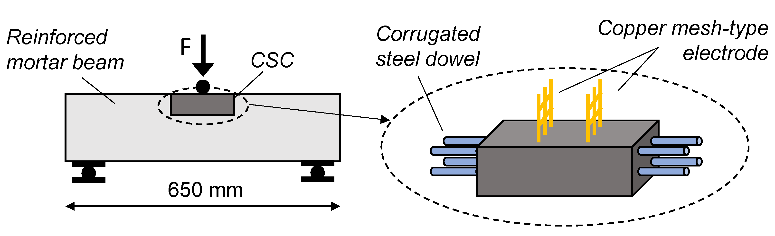
Table 1.
Summary of fabrication parameters of CSCs applied for SHM of structural prototypes 1.
| Filler | Matrix | Electrode | Curing | ||||||||
|---|---|---|---|---|---|---|---|---|---|---|---|
| Ref. | Type | Concentration 2 | Dispersion 3 | Type 4 | w/c | Additive 5 | Type 6 | Nr | Spacing 7 | Type 8 | Duration |
| (-) | (-) | (%) | (-) | (-) | (-) | (-) | (-) | (-) | (mm) | (-) | (d) |
| [71] | CB | 15.00 | MS | C | 0.40 | WR + Df | CN | 4 | 8 | M; OD | 28;2 |
| [72] | CB | 0.50; 1.00; 2.00 | MS | C | 0.35–0.45 | SP + SF | CN | 4 | 10 | S | 28 |
| [73] | Hybrid (CNT + G + CF) | 0.50 | MS + S | M | 0.45 | CG | 2 | 10 | S | 28 | |
| [74] | Hybrid (CNT + CB) | 6.00 | MS | C | 0.50 | FA + WR | SSG | 2 | 10 | S | 28 |
| [75] | CF | 5.00 | MS | RC | 0.48 | SS | 4 | 200 | L | 28 | |
| [76] | CF; SF | 0.70; 18.00 | MS | RC | 0.40–0.50 | FA + WR | CW | 4 | 120 | 28 | |
| [77] | nano CF; CF | 2.00; 1.00 | US; O + S | C | 0.50 | ECW | 4 | 10 | M | 28 | |
| [78] | nano CF | 0.70 | MS | M | 0.42 | WR + SF | CW | 4 | 5 | L; OD | 28; 1 |
| [79] | CF | 1.50 | S | C | 0.38 | WR | ECW | 4 | M; AD | 28 | |
| [53] | MWCNT | 1.50 | S | C | 0.45 | SP | SSM | 4 | 10 | L | 28 |
| [62,80] | MWCNT | 1.50 | S | C | 0.45 | SP | SSM | 4 | 10 | L | 28 |
| [54] | MWCNT | 0.10; 0.25; 0.50; 0.75 | S + ST; S + ST + OH/COOH | C | 0.40 | Df | CWM | 2 | 10 | L; OD | 28; 3 |
| [81] | MWCNT | 0.80 | S + ST | M | 0.33 | CWM | 2 | S | 28 | ||
1 Void cell means that no specific information is provided. 2 Filler concentration expressed as function of weight of cement. 3 Dispersion: Mechanical stirring (MS); Sonication (S); Ultrasonication (US); Oxidation (O); Hydroxyl (OH) or carboxyl (COOH) functionalization; Surfactant (ST). 4 Matrix type: Cement paste (C); Mortar (M); Reinforce concrete (RC). 5 Additive: Water Reducer (WR); Defoamer (Df); Superplasticizer (SP); Silica fume (SF); Fly Ash (FA). 6 Electrode type: Copper net (CN); Copper Gauze (CG); Stainless steel gauze (SSG); Steel stirrups (SS); Copper wire soldered with steel wire mesh (CW); External copper wire connected to conductive paint (ECW); Stainless steel mesh (SSM); Copper wire mesh (CWM). 7 Minimum distance between two consecutive electrodes. 8 Curing type: Moist room (M); Oven-Dry (OD); Laboratory condition (L); Standard condition (S); Air-Dry (AD).
Table 2.
Features of CSC sensors and structural prototypes tested for civil SHM purposes 1.
| Sensor Dimensions | Installation | Prototype | |||||||||
|---|---|---|---|---|---|---|---|---|---|---|---|
| Reference | Bs 2 | Hs 2 | Ls 2 | Type 3 | Number 4 | Member | Bp 5 | Hp 5 | Lp 5 | Material | Loading condition |
| (-) | (mm) | (mm) | (mm) | (-) | (-) | (-) | (mm) | (mm) | (mm) | (-) | (-) |
| [71] | 40 | 30 | 50 | Embedded | 1 | Column | 100 | 100 | 300 | Concrete | Cyclic axial load |
| [72] | 10 | 10 | 30 | Embedded | 1;2 | Beam | 40 | 40 | 160 | Cement paste | Monotonic bending Cyclic bending |
| [73] | 50 | 20 | 50 | Embedded | 1 | Beam Column | 100 | 100 | 500 | Concrete | Monotonic bending Monotonic axial load |
| [74] | 20 | 20 | 50 | Embedded | 1 | Column | 150 | 150 | 300 | Concrete | Monotonic axial load Cyclic axial load |
| [75] | 200 | 30;60;90 | 3000 | Embedded | Beam | RC | Monotonic bending | ||||
| [76] | 305 | 305 | 507 | Embedded | Column | RC | Cyclic lateral load | ||||
| [77] | 20 200 | 20 7 | 80 80 | Attached | 18 8 | Beam | 200 | 300 | 3900 | RC | Cyclic bending |
| [78] | 25.4 | 25.4 | 25.4 | Embedded | 6 | Column | 450 | 450 | 1600 | RC | Cyclic lateral load |
| [79] | 125 | 78 | 350 | Embedded | 2 | Beam | 125 | 350 | 1500 | RC | Monotonic bending |
| [53] | 50 | 50 | 50 | Embedded | 7 | Beam | 250 | 250 | 2000 | RC | Cyclic bending, Vibration |
| [62,80] | 50 | 50 | 50 | Embedded | 7 | Beam | 250 | 250 | 2000 | RC | Vibration test, monotonic bending and environment action |
| [54] | 50 | 50 | 50 | Mechanical | 1 | Beam | 600 | 245 | 4500 | RC | Vibration test |
| [81] | 52 | 52 | 150 | Embedded | 1 | Beam | 130 | 160 | 650 | Reinforced mortar | Monotonic bending |
1 Void cell means that no specific information is provided. 2 Bs, Hs, Ls: cross-section width, cross-sectional depth, length, of the CSC. 3 Installation type: Embedded (E); Attached with a bonding agent (A); Mechanical connected (MC). 4 Number of CSCs installed in each monitored structural prototype. 5 Bp, Hp, Lp: cross-section width, cross-sectional depth, length, of the structural prototype.
Publisher’s Note: MDPI stays neutral with regard to jurisdictional claims in published maps and institutional affiliations. |
© 2021 by the authors. Licensee MDPI, Basel, Switzerland. This article is an open access article distributed under the terms and conditions of the Creative Commons Attribution (CC BY) license (https://creativecommons.org/licenses/by/4.0/).
Share and Cite
MDPI and ACS Style
Cassese, P.; Rainieri, C.; Occhiuzzi, A. Applications of Cement-Based Smart Composites to Civil Structural Health Monitoring: A Review. Appl. Sci. 2021, 11, 8530. https://0-doi-org.brum.beds.ac.uk/10.3390/app11188530
AMA Style
Cassese P, Rainieri C, Occhiuzzi A. Applications of Cement-Based Smart Composites to Civil Structural Health Monitoring: A Review. Applied Sciences. 2021; 11(18):8530. https://0-doi-org.brum.beds.ac.uk/10.3390/app11188530
Chicago/Turabian StyleCassese, Paolino, Carlo Rainieri, and Antonio Occhiuzzi. 2021. "Applications of Cement-Based Smart Composites to Civil Structural Health Monitoring: A Review" Applied Sciences 11, no. 18: 8530. https://0-doi-org.brum.beds.ac.uk/10.3390/app11188530
Note that from the first issue of 2016, this journal uses article numbers instead of page numbers. See further details here.