
A Fast-Reduced Model for an Innovative Latent Thermal Energy Storage for Direct Integration in Heat Pumps


Consiglio Nazionale delle Ricerche (CNR), Istituto di Tecnologie Avanzate per l’Energia “Nicola Giordano” (ITAE), Via Salita S. Lucia sopra Contesse n. 5-98126, 98126 Messina, Italy
*
Author to whom correspondence should be addressed.
Appl. Sci. 2021, 11(19), 8972; https://0-doi-org.brum.beds.ac.uk/10.3390/app11198972
Submission received: 6 September 2021
/
Revised: 17 September 2021
/
Accepted: 23 September 2021
/
Published: 26 September 2021
(This article belongs to the Special Issue Modelling Advanced Materials and Systems for Thermal Energy Storage)
Abstract
:Featured Application
the latent storage unit described in this paper is suitable for application in heat pumps and chillers; either used for space heating/cooling or domestic hot water.
Abstract
In the present paper, the numerical modeling of an innovative latent thermal energy storage unit, suitable for direct integration into the condenser or evaporator of a heat pump is presented. The Modelica language, in the Dymola environment, and TIL libraries were used for the development of a modular model, which is easily re-usable and adaptable to different configurations. Validation of the model was carried out using experimental data under different operating modes and it was subsequently used for the optimization of a design for charging and discharge. In particular, since the storage unit is made up of parallel channels for the heat transfer fluid, refrigerant, and phase change material, their number and distribution were changed to evaluate the effect on heat transfer performance.
1. Introduction
Thermal energy storage is one of the enabling technologies driving the decarbonization of the heating and cooling sector, which, in turn, represents the center of initiatives such as the ‘green deal’ and the ‘renovation wave’, in the view of the massive deployment and integration of renewables in the energy system.
Among the thermal energy storage (TES) technologies employed at a residential level, latent thermal energy storage with the use of phase change materials (PCMs) is not only moving towards commercial maturity [1], but is also the most active segment, with TES systems at research level, as bibliometric analyses of the sector demonstrate [2,3]. However, it still needs to properly address the current challenges that limit its widespread use in buildings and heating/cooling systems. As highlighted in [4,5], application-oriented research should focus on heat transfer enhancement, materials cost reduction, and management/control strategies.
In order to improve the heat transfer within latent TES (LTES), several methods have been proposed, which mainly include an increase of the thermal conductivity of the material itself, the use of extended heat transfer surfaces (e.g., finned structures) in the heat exchanger (HEX), and the application of heat pipes [6,7]. Among these methods, the increase of the thermal conductivity of the material is achieved through the use of highly conductive porous media and the addition of conductive fillers [8,9], which however reduces the overall energy density of the system and can increase the cost of the storage. The use of fins has also been widely investigated [6], and several materials and geometries have been analyzed.
For instance, in [10], a numerical model of a LTES system for solar cooling applications is presented, in which the use of transversal fins was found to be the most effective way to increase heat transfer in a shell-and-tube type heat exchanger. Similarly, in [11] the topology and material of fins in multi-tube LTES units is discussed, and it was found that, through a proper design, the improvement in heat-transfer performance can reach 20%. The design of fins that gives the maximum advantage for the majority of applications at low to mid temperature (i.e., 10 to 100 °C) is a branched design of transversal fins. Aluminum and graphite are materials that allow a fast charge/discharge process. In [12], shell-and-tube and plate fin configurations are compared for medium temperature applications through a numerical study. The results indicate that the advantages of the plate fin configuration are higher flexibility of the design, which can be easily scaled; reliability, since the PCM and heat transfer fluid are completely separated; and a higher amount of exploitable heat during discharge. In [13] and [14], two heat storage configurations for LTES applications are presented, in which the same PCM is used, i.e., a paraffin with a nominal melting temperature of 82 °C. It was found that the use of a plate configuration with short channels enhances heat transfer and, therefore, the achievable power delivered to the user, compared to spaced longitudinal fins.
Such a literature overview demonstrates that the use of finned structures is an effective way to maximize the performance of LTES. However, in order to properly select the most appropriate configuration, the design process has to be carefully defined. This is also a key point in evaluating the different management strategies that can increase the economic profit of latent storage [15]. For this aim, different models can be used. A wide distinction can be made between detailed computational fluid dynamic/finite element models and simplified lumped parameter models that usually simplify the problem in terms of spatial dimensions (i.e., 1D or 2D models against 3D models). The challenges in the modeling of latent storage are mainly linked to the fact that the phase change process is non-linear and, therefore, an exact analytical solution is only possible for extremely simple cases [16]. Moreover, according to the specific layout of the storage, natural convection may occur, which further increases the complexity of the simulation, due to the need for solving a Navier–Stokes equation for the PCM [17]. Finally, PCM properties are temperature-dependent, thus increasing the required number of equations and the computational time to model them. In order to simplify the problem and get accurate, and yet fast, models, suitable for testing different design configurations, different approaches have been proposed.
In [18], a 3D finite element model is developed for a LTES with longitudinal fins using paraffin as the PCM and comparing the numerical results with experimental tests. The model can be simplified during solidification, since during this process natural convection does not occur. In [19], a simplified COMSOL model is implemented, in which a 3D model of only the portion of PCM between the fins is combined with a 1D model of the heat exchanger. The results for paraffin showed a good agreement with the experimental results, during both charge and discharge. In [20], a simplified 3D model is constructed by using an empirical equation for the heat delivered by the PCM, according to the calorimetric measurements at the material level. Another approach, proposed in [21], is the use of a RC model (resistance–capacitance), which was then compared to the 1D–3D coupled model developed in [19]. The deviation of both models from the experiments was in the order of 1 K, but the RC model had a two to three times shorter computational time, which makes it suitable for fast and reliable design. In [22], the simplification assumed is the use of lumped masses for the PCM and the metal of the HEX accuracy. The deviation of the numerical and simulation results was less than 9%; therefore, showing the applicability of such models for design purposes. A simplified model for PCM storages is presented in [23,24], which is realized in Modelica language. The results of the simulations were used to adapt the storage geometry and PCM properties to cover a broad range of applications.
In the present paper, a simplified modelling methodology of LTES is applied to an innovative configuration; i.e., a finned aluminum heat exchanger for refrigeration applications. The novelty of the configuration, whose development is presented in detail in [25,26], is the possibility of directly charging the PCM with the refrigerant of the heat pump cycle, thus, allowing the storage unit to replace the evaporator of a heat pump, while using a separate heat transfer fluid (HTF) during discharge. The model was implemented in the Modelica language using Dymola, and was realized by considering the fluids of the storage (PCM, HTF, refrigerant) as interconnected volumes, according to an array-like fashion, which allows easy scalability of the model. The model was validated under different operating modes using experimental results and then optimization through a parametric analysis was carried out.
2. Latent Thermal Storage Design
The latent thermal energy storage system described in this paper was specifically designed for the integration of PCM into a vapor compression system, in order to reduce the complexity of the integration of such components, as well as the bulkiness of a combined heat pump + TES system. It was manufactured by AKG (Hofgeismar, Germany) and is completely made of dip brazed aluminum 3000 alloy. It mainly consists of a central block, in which the passages for the three fluids are located: the PCM, the HTF, and the refrigerant of the vapor compression system. These consist of an array of parallel channels integrated in a unique container, which removes the need for extra components, as in the case of an external tank. In addition, the distributor for the HTF and the refrigerant are welded. The HTF and refrigerant distributors and manifolds are arranged in order to have a counter flow and, therefore, improve the heat transfer.
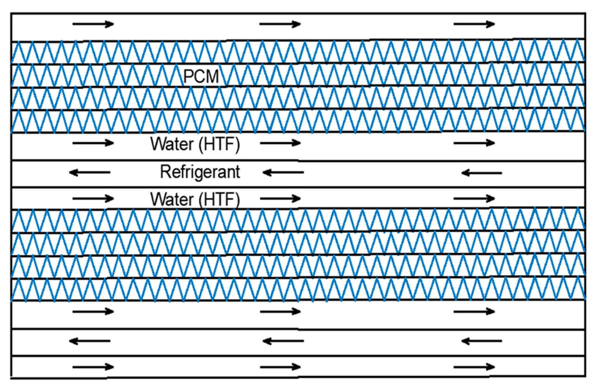
The ordered channel distribution is shown in Figure 1 and was optimized according to the experimental activity described in [25]. The external dimensions of the LTES and the volumes of the fluids for the HEX tested are listed in Table 1. The overall number of channels is 76: 44 for the PCM, 22 for the HTF, and 10 for the refrigerant. The LTES was insulated with 20-mm-thick mineral wool.
3. Model Description
A lumped parameter model was developed in the Modelica language, using the Dymola environment and the commercial TIL libraries for components and media [28]. The following assumptions were made:
- -
- the thermo-physical properties of the refrigerant, the HTF, and the PCM are independent of temperature; however, the properties in the solid phase are different from the properties in the liquid phase;
- -
- HTF is incompressible;
- -
- the temperature of the refrigerant, HTF, and the metal walls varies only in the flow direction (x-direction) along their lengths, which are divided into n nodes;
- -
- radiative heat transfer is not considered;
- -
- the heat loss to the surroundings is negligible;
- -
A schematic view of the model structure is shown in Figure 2, together with the main boundary conditions.
For each cell of refrigerant and HTF, momentum, energy, and mass balance equations are solved. For the refrigerant of the heat pump:
where p (bar) is the pressure, (kg s−1) is the mass flow rate, h (J kg−1) is the specific enthalpy, and (W) is the heat transfer term.
The pressure drop Δp in the refrigerant cell is considered constant and evaluated according to experimental data. The heat transfer term is instead calculated as:
where Uref (W m−2 K−1) is the heat transfer coefficient for the refrigerant cell, A (m2) is the heat transfer area for each cell, k (W m−1 K−1) is the thermal conductivity of the wall material, Dh (m) is the hydraulic diameter of the channel, Re is the Reynolds number, Pr is the Prandtl number, and Nu is the Nusselt number. The friction factor j is calculated as:
with A, B, and C supplied by the heat exchanger manufacturer.
For the HTF:
where cp (J kg−1 K−1) is the specific heat capacity of the heat transfer fluid. Similarly to the case of the refrigerant cell, a constant pressure drop was considered and the heat transfer was calculated as:
The heat transfer coefficient for the HTF cell UHTF was calculated according to a Nu correlation, as in Equation (6), with:
The parameters for the calculation of the friction factor were supplied by the heat exchanger manufacturer.
For the PCM cells, energy balance is implemented as:
The term (W) represents the sum of all the heat flows for the cell, which are due both to the heat transfer within the PCM layer itself, as well as with the HTF. In both cases, only thermal conduction within the PCM cell is considered.
The phase change is modelled using the solid–liquid equilibrium implementation in the TIL media libraries, which makes use of the enthalpy method [10,19]. Accordingly, the phase transition is described by means of effective enthalpy:
where cp,s (J kg−1 K−1) is the specific heat of the solid, cp,l (J kg−1 K−1) is the specific heat of the liquid, L (J kg−1) is the latent heat of melting, T1 (°C) is the onset temperature for melting, T2 (°C) is the offset temperature for the melting process, and γ is the liquid fraction, calculated as:
Initial and Boundary Conditions
A continuity condition between cells (PCM, refrigerant, and HTF) was applied. For each i-th cell:
In addition, the pressure, mass flow rate, and inlet temperature for the refrigerant and the HTF circuits were defined.
Initial conditions applied included a specified uniform temperature for all the refrigerant, HTF, and PCM cells:
Moreover, a steady state condition at the initial point was imposed:
The size of each cell is the core length/10 × core width × fin height. The independence of results from the number of cells considered was verified prior to the simulation under realistic operating conditions.
4. Model Validation
The developed model was validated using the experimental data from a testing campaign carried out for a complete system, including the heat pump and the embedded thermal energy storage. A detailed description of the system, testing conditions, and results is presented in [30]. The testing rig used for the experimental activity consisted of three water storages units connected to different heat sources, to supply the different temperature levels needed for the operation of thermal systems. The inlet and outlet HTF flows of each storage were mixed through the use of high-speed mixing valves to guarantee a constant inlet and the precise regulation of the desired set-point. Heat storage units with charge/discharge power up to 30 kW can be tested. A picture of the system (heat pump + heat storage) connected to the testing rig and the layout of the latent storage are shown in Figure 3. The uncertainty of measurements for this setup was ±0.5 °C for the temperatures and ±700 W for the thermal power [30].
Different operating modes are possible for the storage unit [30]:
- -
- charge mode: the refrigerant of the heat pump is used to solidify the PCM, there is no flow in the HTF circuit;
- -
- discharge mode: the heat pump is off, the HTF is circulated, and the PCM is melted by subtracting the latent heat from the HTF, which is cooled down and delivered to the user;
- -
- parallel charging/discharging mode: the PCM is charged and discharged at the same time. Hence, the heat pump is on and at the same time the HTF circuit is connected to the load.
In order to validate the model, reference tests for each of the investigated operating modes were considered. For the charge process, the case of a test with the PCM starting at an average temperature of 15 °C and fully charged until 0 °C with the heat pump at a part load of 60% was considered. The results are shown in Figure 4a, where a direct comparison between the average measured PCM temperature and the simulated one is presented. It is possible to notice that there was a good agreement between the experiments and the simulation, with deviations lower than 0.5 K. An exception is represented by the temperature range 0–2 °C, corresponding to the material in a fully solid state. In this case, a deviation of 1.2 K was shown, probably due to the enthalpy formulation of the implemented model in Dymola. However, under the designed operating conditions, it is not beneficial to reach such temperatures, also due to a too high reduction in the temperature of the refrigerant of the heat pump, with a, consequently, strong penalization of its efficiency. Accordingly, it is possible to state that the validation in the designed range was successful.
For the discharge process, a test with the PCM starting at −2 °C and ending at 12 °C, with a discharge flow rate of 0.2 kg/s for the HTF was selected. A comparison of the average PCM temperature from the experiments and the simulation is shown in Figure 4b. In this case, the average deviation between the experiments and simulation was about 16%. The larger difference being due to the larger thermal gradient in the heat exchanger, as a consequence of the turbulent flow of the HTF and its uneven distribution, which is more complex to reproduce in lumped parameter modeling. However, considering that this measurement error is in the order of 10%, the error introduced by the simulation for this operating mode can also be considered acceptable for simulation-aided design purposes.
Finally, the validation for parallel operation is shown in Figure 4c. During this operating mode, as described in detail in [30], the temperature of the PCM is almost constant. Therefore, for validation purposes, the temperature of the outlet of the HTF is also shown. It can be seen that the deviation between experiments and simulations is small (1 K), and it is then possible to conclude that the model developed is able to fully describe the operation of the storage under the different operating modes.
The run time was 10 s for 2000 s of storage operation on an Intel i8 laptop.
5. Optimization through Parametric Analysis under Variable Input Conditions
After the model validation, design optimization was carried out through parametric analysis. The main application foreseen for the storage unit is use in residential heat pump systems, and, therefore, only short-term storage periods are foreseen. Accordingly, the main goal of the optimization was the improvement of the heat transfer, rather than the overall amount of energy stored. In order to guarantee that the simulation runs performed for optimization purposes were carried out under realistic operating conditions, the input to the simulations were the measured experimental values (flow rate and temperature of HTF, pressure and temperature in the refrigerant circuit). Therefore, an investigation time range of 4000 s was considered, corresponding to the time range of data availability from the experimental setup.
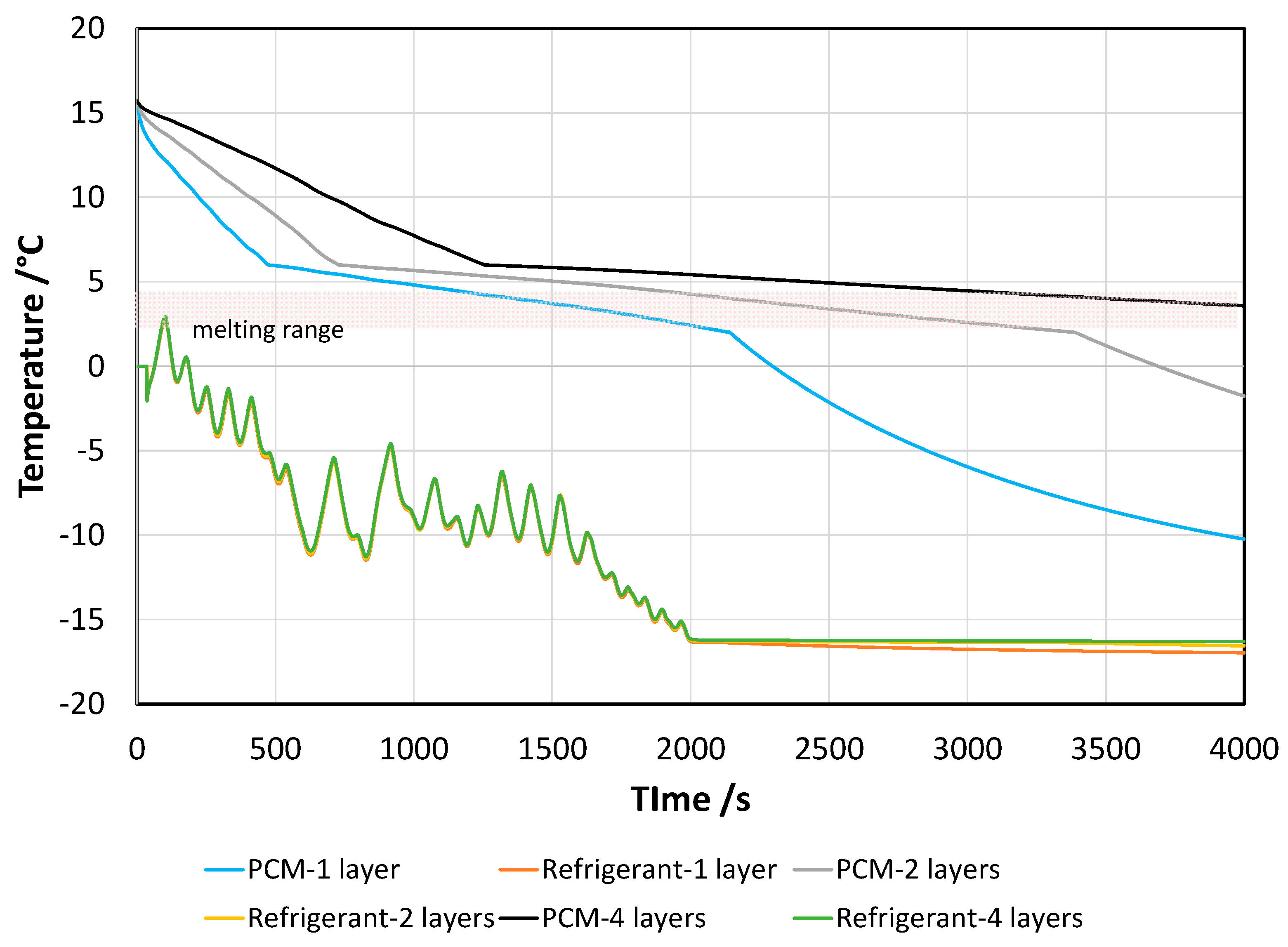
Both charge and discharge processes were investigated. Given the peculiarity of the system, i.e., the charging of the storage directly through the heat exchange between the refrigerant of the compression cycle and the PCM, the main parameter affecting the charge of the storage was the number of stacked PCM layers in between the refrigerant channels. Indeed, as already discussed in [25] for a similar design, since the heat transfer is achieved only through thermal conduction, the main limitation to heat transfer is the thermal conductivity of the PCM. Accordingly, three cases were considered: one, two, and four consecutive PCM layers. For each case, the overall amount of PCM was not changed, only the number of parallel channels was changed. The overall amount of energy that the system can store was then constant for the investigated conditions.
In Figure 5, the results of the parametric analysis are shown; in terms of temperatures in the refrigerant and PCM. The fluctuations in the average temperature of the refrigerant were due to the specific behavior of the heat pump tested in the lab and, more specifically, to the operation of the thermostatic valve. There is a clear difference in the temperature trend for the different cases examined; since the heat transfer for one layer of PCM is better, in the same time-span, all the material in the storage not only completes the phase change, but also sensible heat in the solid phase can be exploited, and the average temperature reached was −10 °C. For the configuration with two PCM layers, the phase change was completed after 3500 s, and a final temperature of −2.5 °C was reached. Instead, in the case of four PCM layers, after 4000 s, not all the material in the storage had completed the phase change, due to the penalization of the heat transfer induced by the low thermal conductivity of the material.
The average thermal power exchanged between the refrigerant and the PCM is reported in Figure 6. For the temperature, during the first part of the charging, the fluctuations in the power are due to the fluctuations in pressure and temperature of the refrigerant, as a consequence of the opening/closing of the thermostatic expansion valve of the heat pump. It is possible to notice that the average power delivered to the user is higher for the case of one layer of PCM and decreases almost linearly with the increase in the number of PCM layers.
It is, however, worth noting that the configuration of one PCM layer, despite being more efficient from the point of view of heat transfer, is also the least advantageous from the point of view of system volume and metal usage. Indeed, in order to keep the same amount of PCM, the amount of metal needed for the one-layer case is much higher than the four-layer, which already amounts to 60% of the overall empty weight of the heat exchanger. In particular, the weight for each additional channel is about 1.2 kg. Accordingly, it is possible to state that, according to the specific application, a good compromise for heat transfer could be a two-layer configuration (in cases where the weight and dimensions are not especially constraining issues) or the four-layer configuration, in which the penalization of heat transfer is compensated by the lower dimensions and weight of the TES.
For the case of discharge, the parameters investigated were the flow rate of the HTF, which was already proven during experiments to be an important parameter in the operation of the system [30], and the number of stacked PCM layers. The results, for the case of four PCM layers and a HTF inlet of 12 °C are shown in Figure 7 and Figure 8. From Figure 7, it is possible to notice that the same trend is observed for all the cases; i.e., a linear temperature increase, with a slope change when the melting process starts. What is interesting to note is that, for all the flow rates investigated, the PCM had still not completed the phase change after 2000 s, and that there was a considerable temperature difference between the PCM and the HTF. Indeed, especially for the case of 0.3 kg/s and 0.5 kg/s, already, after 1000 s the HTF outlet temperature was close to the inlet one (12 °C); thus, indicating that no useful effect can actually be supplied to the user. The average power supplied to the user is shown in Figure 8. During the first seconds, there is a peak, which increases with increasing flow rates, but already after 250 s, there is a strong decrease in the power supplied; down to values of 4 kW to 2 kW, when passing from 1.2 kg/s to 0.3 kg/s. As is common in other latent storage systems, the optimal HTF flow rate depends on the intended application [13,14]; if high power has to be supplied to the user, it is possible to increase the HTF flow rate, whereas to have a more constant supply for a longer time, lower HTF flow rates are needed.
However, as clearly highlighted, the configuration with four PCM layers still has several limitations, in terms of the heat transfer, as proven by the temperature difference between the PCM and the HTF. Such features might be exploited through suitable management strategies, as will be discussed in the next section. However, in order to highlight the effect of the PCM volume in between the HTF channels, the cases of one, two, and four layers were investigated. Figure 9 depicts the average PCM temperature evolution for the layouts chosen. There is a clear effect when reducing the number of layers: the phase transition is completed in less than 500 s for one-layer, 1200 s for two-layers, and almost 2500 s for four-layers. In order for the PCM to reach the temperature of the HTF, and therefore complete the heat exchange, also including the sensible part, it takes 1500 s for the one-layer layout, 2500 s for two-layers, and more than 4000 s for four-layers. Nonetheless, as already stated for the case of charging, reducing the number of layers would strongly increase the weight and dimensions of the heat exchanger, thus penalizing the heat transfer density. Moreover, in all the cases where a longer period of operation disconnected from the grid (i.e., without using a heat pump) is foreseen, the four-layer case can be the most advantageous one. A good compromise can be instead obtained with the two-layer layout.
6. Comparison with the State-of- the-Art
The combination of heat pumps with LTES is gaining interest, due to the possibility of better managing the operation of the heat pump, especially when driven by renewables. A vast review of the possible couplings between heat pumps and LTES is discussed in [31]. However, in the majority of research studies, the integration of the PCM and the heat pump cycle is not direct, but is rather achieved through the use of an external tank. In [32], the use of ice as a PCM for direct embedding in the evaporator of a heat pump is investigated numerically, but no details on the possible layout of the storage are given and the results are reported in terms of exergy analysis and power consumption for the heat pump; showing that a reduction in the electricity consumption of the heat pump is possible. In [33], the experimental evaluation of a PCM (RT42, with melting temperature of 42 °C) for integration in the condenser of a heat pump is discussed. In this case, the optimization of the melting temperature of the paraffin is achieved by switching from air-source to solar-assisted operation. The solar-assisted operation guaranteed lower melting/solidification times, due to the higher temperature difference that was possible. In [34], a three-sleeve HEX design for integration in the heat pump cycle for heating and cooling purposes is discussed. Compared to the design presented in the current paper, the passages for the PCM, refrigerant, and water are concentric annuli. Interestingly, the profiles for the temperature and pressure in the storage are similar to those described for the present design. In particular, similarities include some fluctuations in the evaporator power of the heat pump, due to fluctuations in the temperature of the refrigerant, as well as the general initial rapid decrease in PCM temperature (during charging) or increase (during discharge), followed by a change in the slope of temperature once the melting range is reached, and a slow variation of temperature afterwards. However, compared to the three-sleeve design, the configuration presented here has some advantages, such as the higher storage density, due to the higher packing factor of the HEX, and the easier scalability to larger scales, due to the array-like configuration. A peculiarity of the current configuration, which also simplifies the design and analysis of the HEX, is the thermal conduction dominating the heat transfer mechanism, since, due to the arrangement of channels and their dimensions, convection does not occur. Despite having found that convection can boost the melting process of PCMs [18,35], it was, however, found that, at HEX level, it is still more convenient to use heat transfer enhancement techniques, e.g., through fins or other methods, to increase the heat exchange area rather than exploiting natural convection in the paraffin [36]. This is due to the low thermal conductivity of the paraffin, which causes a slow onset of natural convection during melting, thus increasing the time needed for charging, which is not desirable for applications in heat pumps.
Such a literature overview further reinforces the advancements presented in the current configuration, while showing that the evaluation of systems is still mostly based on experimental measurements; whereas, a more organic design requires suitable tools, such as the one presented here.
7. Conclusions
The present paper describes a reduced numerical model, realized in the Modelica language with Dymola software, for the design of an innovative heat exchanger suitable for application in heat pumps. The peculiarity of this heat exchanger is the possibility of being used, at the same time, as the evaporator of a vapor compression heat pump and a latent thermal energy storage for the same heat pump. It is made of aluminum and includes parallel finned channels for the PCM, the heat transfer fluid, and the refrigerant.
A parametric model was developed, which considers each flow path as a sequence of control volumes, and which is fully parameterized and easily scalable. Validation of the model under different operating conditions (charge, discharge, simultaneous charge/discharge) is presented. Deviations from experimental results were within measurement uncertainty.
Accordingly, a parametric analysis was carried out, by varying the number of layers of PCM between the two refrigerant and heat transfer fluid channels and the flow rate of the heat transfer fluid, with the aim of improving the heat exchange. The results indicated that faster melting/solidification times were achieved for the case of one layer of PCM, but a good compromise between heat transfer performance and system dimensions/weight can be achieved with two PCM layers. Further techno-economic evaluations will be carried out in future works, since this represents the very first prototype of this kind, and, therefore, proper economic evaluations are not possible.
Due to its flexibility and intrinsic reusability, the model here presented can be used for other applications and further enhancements of heat exchanger design, for instance, through a systematic parametric assessment, multi-variable optimization techniques, or the evaluation of different PCMs.
Author Contributions
Conceptualization, methodology, investigation, software, writing: V.P.; Conceptualization, methodology, validation, writing: A.F. All authors have read and agreed to the published version of the manuscript.
Funding
This project was partially funded by the European Union’s Horizon 2020 research and innovation programme under grant agreement No 768824 (HYBUILD).
Institutional Review Board Statement
Not applicable.
Informed Consent Statement
Not applicable.
Data Availability Statement
Data available upon request.
Conflicts of Interest
The authors declare no conflict of interest.
References
- Markets, M. Phase Change Material Market—Global Forecast to 2025. Available online: https://www.marketsandmarkets.com/Market-Reports/advanced-phase-change-material-pcm-market-1087.html (accessed on 1 September 2021).
- Calderón, A.; Barreneche, C.; Hernández-Valle, K.; Galindo, E.; Segarra, M.; Fernández, A.I. Where is Thermal Energy Storage (TES) research going?—A bibliometric analysis. Sol. Energy 2020, 200, 37–50. [Google Scholar] [CrossRef]
- Borri, E.; Zsembinszki, G.; Cabeza, L.F. Recent developments of thermal energy storage applications in the built environment: A bibliometric analysis and systematic review. Appl. Therm. Eng. 2021, 189, 116666. [Google Scholar] [CrossRef]
- Sevault, A.; Vullum-Bruer, F.; Tranås, O.L. Active PCM-Based Thermal Energy Storage in Buildings. Ref. Modul. Earth Syst. Environ. Sci. 2020. [Google Scholar] [CrossRef]
- Yang, L.; Villalobos, U.; Akhmetov, B.; Onn, K.J.; Gil, A.; Tan, W.L.; Romagnoli, A. Active TES With PCM for Refrigeration Applications. Ref. Modul. Earth Syst. Environ. Sci. 2021. [Google Scholar] [CrossRef]
- Li, Z.; Lu, Y.; Huang, R.; Chang, J.; Yu, X.; Jiang, R.; Yu, X.; Roskilly, A.P. Applications and technological challenges for heat recovery, storage and utilisation with latent thermal energy storage. Appl. Energy 2021, 283, 116277. [Google Scholar] [CrossRef]
- Ibrahim, Z.; Newby, S.; Hassani, V.; Ya’akub, S.R.; Bakar, S.A.; Razlan, Z.; Khairunizam, W. A review of the application and effectiveness of heat storage system using phase change materials in the built environment. AIP Conf. Proc. 2021, 2339, 020131. [Google Scholar]
- Mohamed, S.A.; Al-Sulaiman, F.A.; Ibrahim, N.I.; Zahir, M.H.; Al-Ahmed, A.; Saidur, R.; Yılbaş, B.S.B.; Sahin, A.Z.A.; Hasan Zahir, M.; Al-Ahmed, A.; et al. A review on current status and challenges of inorganic phase change materials for thermal energy storage systems. Renew. Sustain. Energy Rev. 2017, 70, 1072–1089. [Google Scholar] [CrossRef]
- Du, K.; Calautit, J.; Wang, Z.; Wu, Y.; Liu, H. A review of the applications of phase change materials in cooling, heating and power generation in different temperature ranges. Appl. Energy 2018, 220, 242–273. [Google Scholar] [CrossRef]
- Palomba, V.; Brancato, V.; Palomba, G.; Borsacchi, S.; Forte, C.; Freni, A.; Frazzica, A. Latent Thermal Storage for Solar Cooling Applications: Materials Characterization and Numerical Optimization of Finned Storage Configurations. Heat Transf. Eng. 2019, 40, 1033–1048. [Google Scholar] [CrossRef]
- Pizzolato, A.; Sharma, A.; Ge, R.; Maute, K.; Verda, V.; Sciacovelli, A. Maximization of performance in multi-tube latent heat storage—Optimization of fins topology, effect of materials selection and flow arrangements. Energy 2020, 203, 114797. [Google Scholar] [CrossRef]
- Riahi, S.; Saman, W.Y.; Bruno, F.; Belusko, M.; Tay, N.H.S. Performance comparison of latent heat storage systems comprising plate fins with different shell and tube configurations. Appl. Energy 2018, 212, 1095–1106. [Google Scholar] [CrossRef]
- Palomba, V.; Brancato, V.; Frazzica, A. Experimental investigation of a latent heat storage for solar cooling applications. Appl. Energy 2017, 199, 347–358. [Google Scholar] [CrossRef]
- Palomba, V.; Brancato, V.; Frazzica, A. Thermal performance of a latent thermal energy storage for exploitation of renewables and waste heat: An experimental investigation based on an asymmetric plate heat exchanger. Energy Convers. Manag. 2019, 200, 112121. [Google Scholar] [CrossRef]
- Arena, S.; Casti, E.; Gasia, J.; Cabeza, L.F.; Cau, G. Numerical analysis of a latent heat thermal energy storage system under partial load operating conditions. Renew. Energy 2018, 128, 350–361. [Google Scholar] [CrossRef]
- Madad, A.; Mouhib, T.; Mouhsen, A. Phase Change Materials for Building Applications: A Thorough Review and New Perspectives. Buildings 2018, 8, 63. [Google Scholar] [CrossRef] [Green Version]
- Charvát, P.; Štětina, J.; Mauder, T.; Klimeš, L. Visual monitoring of the melting front propagation in a paraffin-based PCM. EPJ Web Conf. 2017, 143, 02042. [Google Scholar] [CrossRef]
- Kirincic, M.; Trp, A.; Lenic, K. Influence of natural convection during melting and solidification of paraffin in a longitudinally finned shell-and-tube latent thermal energy storage on the applicability of developed numerical models. Renew. Energy 2021, 179, 1329–1344. [Google Scholar] [CrossRef]
- Neumann, H.; Palomba, V.; Frazzica, A.; Seiler, D.; Wittstadt, U.; Gschwander, S.; Restuccia, G. A simplified approach for modelling latent heat storages: Application and validation on two different fin-and-tubes heat exchangers. Appl. Therm. Eng. 2017, 125, 41–52. [Google Scholar] [CrossRef]
- Pan, C.; Vermaak, N.; Wang, X.; Romero, C.; Neti, S. A fast reduced model for a shell-and-tube based latent heat thermal energy storage heat exchanger and its application for cost optimal design by nonlinear programming. Int. J. Heat Mass Transf. 2021, 176, 121479. [Google Scholar] [CrossRef]
- Neumann, H.; Gamisch, S.; Gschwander, S. Comparison of RC-model and FEM-model for a PCM-plate storage including free convection. Appl. Therm. Eng. 2021, 196, 117232. [Google Scholar] [CrossRef]
- Mehmood, T.; Shah, N.U.H.; Ali, M.; Biwole, P.H.; Sheikh, N.A. Simplified mathematical model and experimental analysis of latent thermal energy storage for concentrated solar power plants. J. Energy Storage 2021, 41, 102871. [Google Scholar] [CrossRef]
- Zauner, C.; Hengstberger, F.; Etzel, M.; Lager, D.; Hofmann, R.; Walter, H. Experimental characterization and simulation of a fin-tube latent heat storage using high density polyethylene as PCM. Appl. Energy 2016, 179, 237–246. [Google Scholar] [CrossRef]
- Zauner, C.; Hengstberger, F.; Mörzinger, B.; Hofmann, R.; Walter, H. Experimental characterization and simulation of a hybrid sensible-latent heat storage. Appl. Energy 2017, 189, 506–519. [Google Scholar] [CrossRef]
- Mselle, B.D.; Vérez, D.; Zsembinszki, G.; Borri, E.; Cabeza, L.F. Performance Study of Direct Integration of Phase Change Material into an Innovative Evaporator of a Simple Vapour Compression System. Appl. Sci. 2020, 10, 4649. [Google Scholar] [CrossRef]
- Zsembinszki, G.; Fernández, A.G.; Cabeza, L.F. Selection of the appropriate phase change material for two innovative compact energy storage systems in residential buildings. Appl. Sci. 2020, 10, 2116. [Google Scholar] [CrossRef] [Green Version]
- Bell, I.H.; Wronski, J.; Quoilin, S.; Lemort, V. Pure and Pseudo-pure Fluid Thermophysical Property Evaluation and the Open-Source Thermophysical Property Library CoolProp. Ind. Eng. Chem. Res. 2014, 53, 2498–2508. [Google Scholar] [CrossRef] [PubMed] [Green Version]
- Palomba, V.; Nowak, S.; Dawoud, B.; Frazzica, A. Dynamic modelling of Adsorption systems: A comprehensive calibrateddataset for heat pump and storage applications. J. Energy Storage 2021, 33, 102148. [Google Scholar] [CrossRef]
- Palomba, V.; Varvagiannis, E.; Karellas, S.; Frazzica, A. Hybrid adsorption-compression systems for air conditioning in efficient buildings: Design through validated dynamic models. Energies 2019, 12, 1161. [Google Scholar] [CrossRef] [Green Version]
- Palomba, V.; Bonanno, A.; Brunaccini, G.; Aloisio, D.; Sergi, F.; Dino, G.E.; Varvaggiannis, E.; Karellas, S.; Nitsch, B.; Strehlow, A.; et al. Hybrid Cascade Heat Pump and Thermal-Electric Energy Storage System for Residential Buildings: Experimental Testing and Performance Analysis. Energies 2021, 14, 2580. [Google Scholar] [CrossRef]
- Pardiñas, Á.Á.; Alonso, M.J.; Diz, R.; Kvalsvik, K.H.; Fernández-Seara, J. State-of-the-art for the use of phase-change materials in tanks coupled with heat pumps. Energy Build. 2017, 140, 28–41. [Google Scholar] [CrossRef] [Green Version]
- Hoseini Rahdar, M.; Emamzadeh, A.; Ataei, A. A comparative study on PCM and ice thermal energy storage tank for air-conditioning systems in office buildings. Appl. Therm. Eng. 2016, 96, 391–399. [Google Scholar] [CrossRef]
- Koşan, M.; Aktaş, M. Experimental investigation of a novel thermal energy storage unit in the heat pump system. J. Clean. Prod. 2021, 311, 127607. [Google Scholar] [CrossRef]
- Niu, F.; Ni, L.; Yao, Y.; Yu, Y.; Li, H. Performance and thermal charging/discharging features of a phase change material assisted heat pump system in heating mode. Appl. Therm. Eng. 2013, 58, 536–541. [Google Scholar] [CrossRef]
- Wang, Y.; Wang, L.; Xie, N.; Lin, X.; Chen, H. Experimental study on the melting and solidification behavior of erythritol in a vertical shell-and-tube latent heat thermal storage unit. Int. J. Heat Mass Transf. 2016, 99, 770–781. [Google Scholar] [CrossRef]
- Frazzica, A.; Palomba, V.; Rosa, D.L.; Brancato, V. Experimental comparison of two heat exchanger concepts for latent heat storage applications. Energy Procedia 2017, 135, 183–192. [Google Scholar] [CrossRef]
Figure 1.
Channel distribution in the latent storage. Coolant indicates the HTF.

Figure 2.
Schematic layout of the lumped model of the three-fluids heat exchanger with latent thermal storage.
Figure 2.
Schematic layout of the lumped model of the three-fluids heat exchanger with latent thermal storage.

Figure 3.
(a) heat pump and latent heat storage system installed in the lab during the testing campaign. (b) schematic representation of the three-fluid heat exchanger.
Figure 3.
(a) heat pump and latent heat storage system installed in the lab during the testing campaign. (b) schematic representation of the three-fluid heat exchanger.

Figure 4.
Model validation for the different operating modes. (a) charge; (b) discharge; (c) parallel operation.
Figure 4.
Model validation for the different operating modes. (a) charge; (b) discharge; (c) parallel operation.


Figure 5.
Temperatures in the PCM and refrigerant circuit during charging for different numbers of stacked PCM layers.
Figure 5.
Temperatures in the PCM and refrigerant circuit during charging for different numbers of stacked PCM layers.

Figure 6.
Thermal power during charging for different numbers of stacked PCM layers.

Figure 7.
Average PCM temperature for different HTF flow rates during discharge for four layers and an HTF inlet at 12 °C.
Figure 7.
Average PCM temperature for different HTF flow rates during discharge for four layers and an HTF inlet at 12 °C.

Figure 8.
Discharge power for different HTF flow rates for four layers and an HTF inlet at 12 °C.

Figure 9.
Average PCM temperature for different numbers of stacked PCM layers during discharge. HTF flow rate 0.5 kg/s, HTF inlet 12 °C.
Figure 9.
Average PCM temperature for different numbers of stacked PCM layers during discharge. HTF flow rate 0.5 kg/s, HTF inlet 12 °C.


Table 1.
Main features of the latent TES investigated.
| PCM | Refrigerant | Coolant | |
|---|---|---|---|
| volume (dm3) | 52.5 | 2.2 | 5.4 |
| hydraulic diameter (m) | 0.0035 | 0.0022 | 0.0024 |
| cross sectional area (m2) | 0.0534 | 0.0021 | 0.0054 |
| heat transfer area (m2) | 57.7 | 3.94 | 8.83 |
| number of passages | 44 | 10 | 22 |
| core length × width × depth (m) | 1 × 0.60 × 0.16 | ||
| empty weight (kg) (Al) | 110 | ||
Table 2.
Properties of the PCM.
| Phase change temperature range (°C) | 2–4 |
| Density (liquid) (kg m−3) | 770 |
| Density (solid) (kg m−3) | 880 |
| Specific heat (kJ kg−1 K−1) | 2 |
| Melting latent heat (kJ kg−1) | 175 |
| Volume expansion (%) | 12.5 |
| Thermal conductivity (W m−1 K—1) | 0.2 |
Publisher’s Note: MDPI stays neutral with regard to jurisdictional claims in published maps and institutional affiliations. |
© 2021 by the authors. Licensee MDPI, Basel, Switzerland. This article is an open access article distributed under the terms and conditions of the Creative Commons Attribution (CC BY) license (https://creativecommons.org/licenses/by/4.0/).
Share and Cite
MDPI and ACS Style
Palomba, V.; Frazzica, A. A Fast-Reduced Model for an Innovative Latent Thermal Energy Storage for Direct Integration in Heat Pumps. Appl. Sci. 2021, 11, 8972. https://0-doi-org.brum.beds.ac.uk/10.3390/app11198972
AMA Style
Palomba V, Frazzica A. A Fast-Reduced Model for an Innovative Latent Thermal Energy Storage for Direct Integration in Heat Pumps. Applied Sciences. 2021; 11(19):8972. https://0-doi-org.brum.beds.ac.uk/10.3390/app11198972
Chicago/Turabian StylePalomba, Valeria, and Andrea Frazzica. 2021. "A Fast-Reduced Model for an Innovative Latent Thermal Energy Storage for Direct Integration in Heat Pumps" Applied Sciences 11, no. 19: 8972. https://0-doi-org.brum.beds.ac.uk/10.3390/app11198972
Note that from the first issue of 2016, this journal uses article numbers instead of page numbers. See further details here.