
Development of Cybersecurity Technology and Algorithm Based on Quantum Computing


Department of Software and Communications Engineering, Hongik University, Sejong 30016, Korea
*
Author to whom correspondence should be addressed.
Appl. Sci. 2021, 11(19), 9085; https://0-doi-org.brum.beds.ac.uk/10.3390/app11199085
Submission received: 31 August 2021
/
Revised: 22 September 2021
/
Accepted: 24 September 2021
/
Published: 29 September 2021
(This article belongs to the Special Issue Emerging Technologies for Next Generation Applied Science System including Selected Papers from ICGHIT 2021)
Abstract
:Many hacking incidents are linked to work files because most companies work with them. However, a variety of file encryption and decryption methods have been proposed. Existing file encryption/decryption technologies are under threat as hacking technologies advance, necessitating the development of stronger encryption algorithms. Therefore, in this study, we propose a modified advanced encryption standard (AES) algorithm and use quantum computing to encrypt/decrypt AES image files. Because the shift is regular during the AES Shift Row procedure, the change technique led the shift to become irregular when using quantum random walk. Computing resources and speeds were simulated using IBM Qiskit quantum simulators for performance evaluation, whereas encryption performance was assessed using number of pixels change rate (NPCR) and unified average changing intensity (UACI).
1. Introduction
Corporate data are frequently stored as files, and encryption techniques have long been required to ensure security. However, as brute-force attacks get more sophisticated, many existing encryption methods are at risk, necessitating the development of a new encryption algorithm.
Therefore, in this study, we used the advanced encryption standard (AES) algorithm, which is a well-known brute force attack-resistant algorithm for file encryption/decryption. In addition, we uniquely used quantum computing to improve the performance of traditional file encryption and decryption algorithms. Quantum computing is expected to take existing information and communication technologies to new levels based on fast computing power and strong security.
We show that the AES algorithm can be implemented using quantum gates and propose that AES be implemented with random number generation. Shift Row moves each data to match in the traditional AES encryption process. Because decryption can reverse the order, this can be anticipated in order. Thus, we modify the shift row’s performance to move randomly, making the order in decryption difficult to predict.
However, knowing the algorithm can predict random numbers in the case of pseudorandom numbers. Therefore, in this paper, we modify the AES algorithm using quantum random walk, which generates random numbers that are unexpected owing to the characteristics of qubits, and compare them to the AES algorithm using pseudorandom numbers.
We target the existing file encryption system [1] in Figure 1, where our quantum-gate-based AES in progress can be applied. The file monitoring system operates in real-time. The file encryption system encrypts the file when an access event (read, write, etc.) to a file is detected. The AES is a symmetric key algorithm; hence, the user decrypts the key used for the encryption and accesses the file. The file restore system restores the file, even if a file is damaged due to a disaster or hacking. It also prevents secondary damage, where internal information is leaked through the encryption system, even if the file is leaked.
The paper is organized as follows: Section 2 describes the architecture of the AES algorithm. Section 3 introduces quantum computing and quantum gate. Section 4 compares the performances of the classical logic gate and the quantum gate used in the quantum simulation. Section 5 explains how random numbers are generated and proposes algorithms that apply them. Section 6 experiments and compares the proposed algorithms. Section 7 describes the conclusion and future work.
2. Advanced Encryption Standard
The AES is a symmetric key algorithm that uses the same key during encryption and decryption. It can have 128 bits, 192 bits, and 256 bits with encryption keys and consists of 10, 12, and 14 rounds running along with the size of the encryption key.
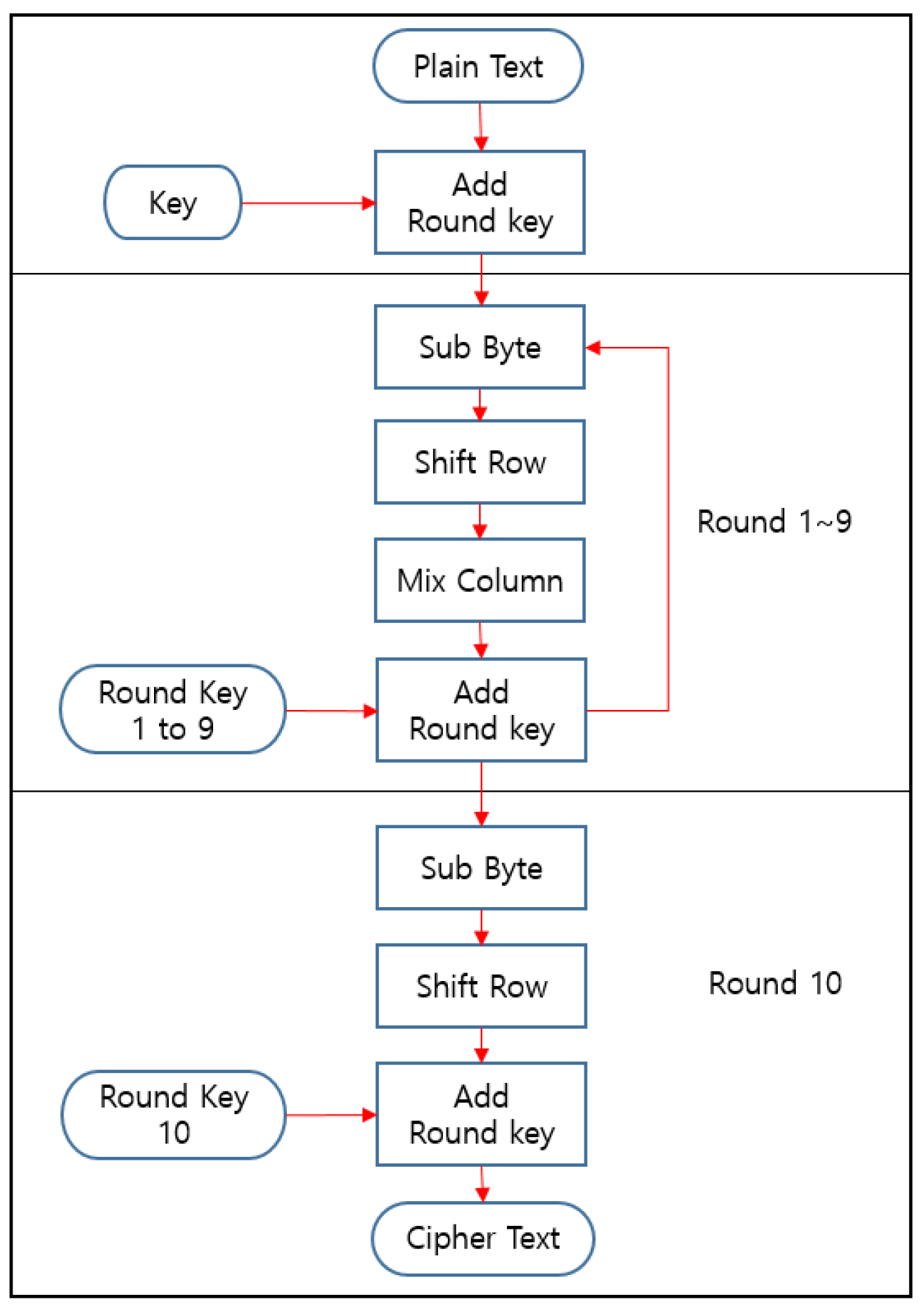
Figure 2 presents AES-128, with the round number as 10. The Add Round Key operation is performed by Plain Text and Key that were first entered. Nine round transformations consisting of Sub Byte, Shift Row, Mix Column, and Add Round Key are then performed. In Round 10, it finally performs Sub Byte, Shift Row, and Add Round Key conversion, except for Mix Column for encryption. Decryption is the opposite process of encryption.
3. Quantum Computing/Quantum Gate
3.1. Quantum Computing and Quantum Simulator
Quantum computing processes information in qubits to use the principles of quantum mechanics. However, the qubit indicating the status of a quantum particle is easily transformed into a decoherence state by the influence of the external environment; hence, it should be kept at a cryogenic state to avoid external influences. Equipment used to maintain cryogenic conditions is also expensive. Therefore, global IT companies developing quantum systems provide quantum simulators.
A quantum simulator is a software program that can run and test quantum algorithms on a classical computer like running quantum algorithms on a quantum computer. In the future, when quantum computers are commercialized, users will be able to run applications on them.
3.2. Quantum Bit(Qubit)
Figure 3 shows the shape of the Qubit. A qubit is the smallest unit of information used in quantum computers. Qubit can have 0 and 1 simultaneously until measurement due to superposition. In the event of measurement or interference, it will have one value as is the classical bit. N qubits are represented by a superposition vector in a 2n dimensional Hilbert space, called an orthonormal basis. For a single qubit, it can be represented as a|0> + b|1>, where a and b are complex numbers satisfying |a|2 + |b|2 = 1.
3.3. Quantum Superposition and Quantum Entanglement
Quantum superposition is a state of having multiple possibilities at the same time. This state exists as a probability until measurement, which allows them to perform operations as fast as 2Qubit times compared to classical computers. Quantum entanglement is a phenomenon in which a particle is split into two and placed at a very long distance. When one side’s state is determined, the other side’s state is also determined. For example, assume that you put one quantum on Earth and the other one entangled to it in a very distant universe. If a quantum state on Earth is determined, a quantum in the distant universe is also determined. Quantum gates are built on these properties, and some quantum gates can replace classical logic gates.
4. Transforming the Classical AES Algorithm into a Quantum-Gate-Based AES Algorithm
4.1. AES Algorithm Analysis
The AES consists of several processes (Figure 2).
4.1.1. Add Round Key
The Add Round Key does the XOR operation of Plain Text and Key. Both Plain Text and Key must be changed to a matrix to perform an XOR operation, in which case, the AND operation is used.
4.1.2. Sub Byte
Sub Byte is an operation that replaces data in 1-byte increments and using S-box tables. The S-box is shown in Figure 4, if the input is 7b (hexadecimal), the result is 21 (hexadecimal).
4.1.3. Shift Row
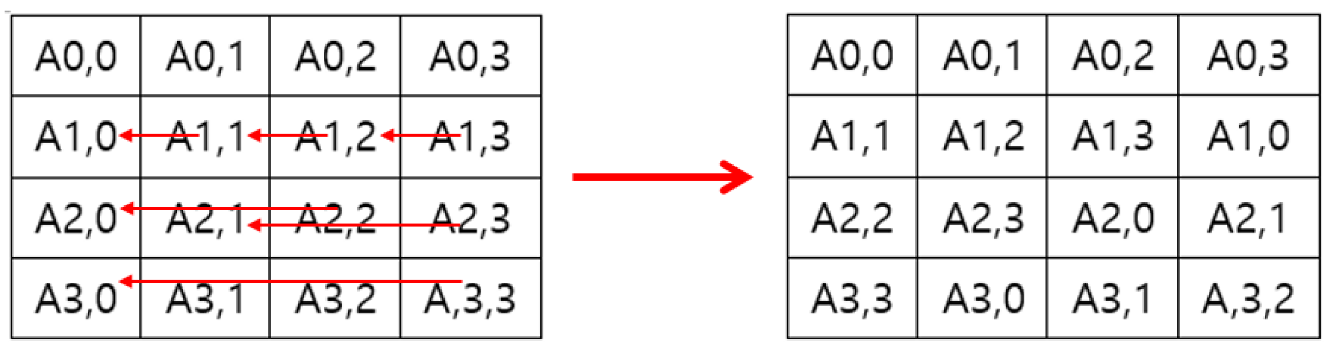
As we can see Figure 5, Shift Row performs shift operations differently on a row basis. Leave the first row. The second row 1 shifts to the left. The third row 2 shifts to the left. The last row 3 shifts to the left.
4.1.4. Mix Column
Each byte proceeds with a specific matrix and multiplication operation. It is a multiplication of the matrix; hence, addition operations occur and the XOR.
4.1.5. Key Schedule
The AES uses a key schedule to expand a short key into a number of separate round keys. The key schedule produces the needed round keys from the initial key. In this process, the Rcon table (Figure 6) is used, and the XOR operation is performed.
4.1.6. Cipher Text
After completing all the processes in the AES, the matrix must be converted back to a ciphertext, where the OR operation is used.
4.2. Quantum Gate to Classical Logic Gate Association
As analyzed in Section 4.1, the AND, OR, and XOR operations are performed during the AES encryption. We tried to implement the required classical logic gate as the quantum gate to utilize quantum computing. The transformation of each gate is as follows:
4.2.1. Classical AND Gate
The classical AND gate is shown in Figure 7. The classical AND gate can be replaced with the Toffoli gate.
The Toffoli gate is shown in Figure 8. The Toffoli gate is a gate in which two qubit states affect one qubit state. In Figure 8, the NOT operation is performed in the third line if both A and B are |1>.
Table 1 compares the classical AND gate and the Toffoli gate.
4.2.2. Classical OR Gate
The classical OR gate can be made from a combination of NOT and classical AND gates. This is represented in Figure 9.
We described the classical AND gate earlier; hence, we will only describe the classical NOT gate here.
The classical NOT gate is shown in Figure 10. The classical NOT gate can be replaced by the Pauli-X gate.
The Pauli-X gate is shown in Figure 11. The Pauli-X gate rotates the qubit to the X-axis and changes it to |0> if the qubit is |1>. It changes the qubit to |1> if it is |0>.
Table 2 compares the classical NOT gate with the Pauli-X gate.
4.2.3. Classical XOR Gate
The classical XOR gate is shown in Figure 12. The classical XOR gate can be replaced with the controlled-NOT (CNOT) gate.
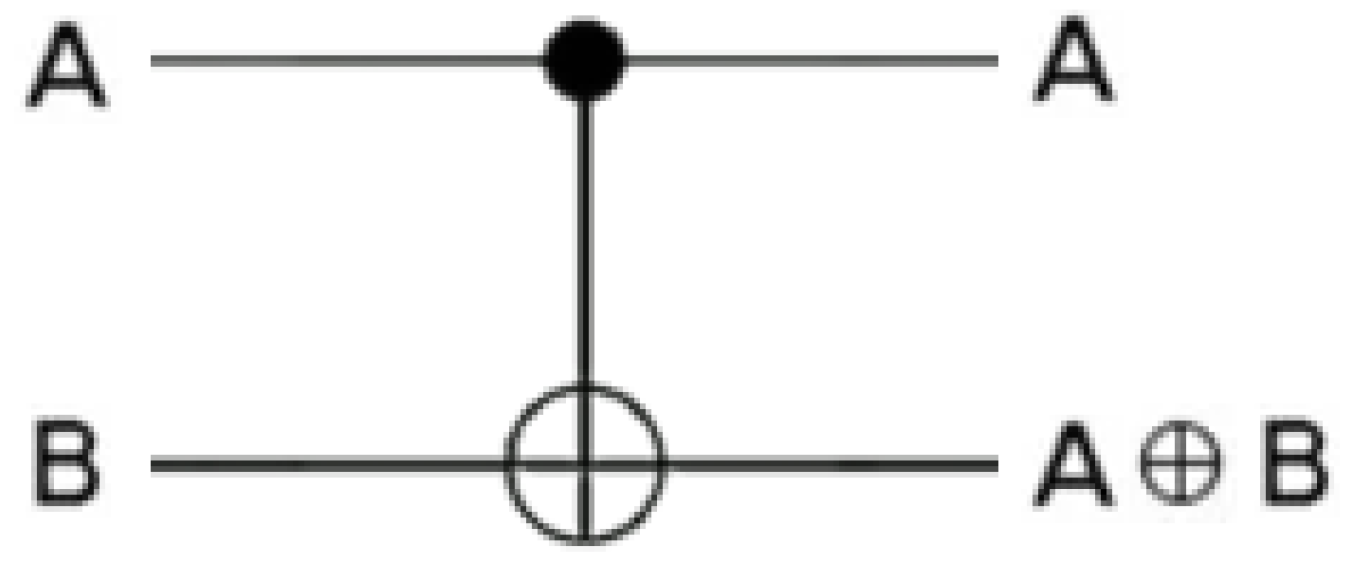
The CNOT gate is shown in Figure 13. The CNOT gate is where you can see the entanglement of two qubits. The state of the first qubit affects that of the second qubit. The CNOT gate performs the NOT operation on B if A is |1>. This is the same as the classical XOR operation (i.e., if the two bits are the same, the result is 0; if the two bits are different, the result is 1). The explanation for this is depicted in Table 3.
4.3. Quantum Computing Programming
Based on Section 4.2, we proceeded herein with Qiskit, a quantum computer platform developed by IBM [2]. We performed the development through a quantum simulator. Let us now see how Section 4.2 is applied.
First, we assign a Quantum Resistor to store the qubit and a Classical Register to store the Classical bit for each bit. The Quantum Register stores all qubits in the form of a list. The Classical Register stores classical bits. These classical bits can only be used if the qubits are measured.
Second, we create a quantum circuit to run each register [3]. A quantum circuit is constructed based on the configured registers. You can also add other registers to the created quantum circuit and visually identify them, if necessary.
Third, the quantum gate corresponding to each classic logic gate operation is applied to the quantum circuit. Inputs are assumed to be Input1 = 1101 and Input2 = 0110.
Further, q424, q431, and q442 can be seen in Figure 14, Figure 15 and Figure 16. They simply mean Qubit and the numbers (424, 431 and 442) do not have meaning.
4.3.1. Classical AND Gate Using Toffoli Gate
Descriptions 1 to 4 below describe Figure 14.
- Initialize qubit’s initial state to |0>.
- Calculate from the last digit (fourth) of the input values. The last digit of Input1 is 1. The last digit of Input2 is 0. That is, qubit_0(q424_0) should be |1>, and qubit_1(q424_1) should be |0> [4]. Therefore, apply the Pauli-X gate to qubit_1. Qubit_2(q424_2) must be |0> because it must satisfy the AND operation. The measurement of qubit_2 returns the result of the AND operation.
- Calculate the third digit of the input values. The third digit of Input1 is 0. The last digit of Input2 is 1. That is, qubit_3(q424_3) should be |0>, and qubit_4(q424_4) should be |1>. Therefore, apply the Pauli-X gate to qubit_4. The measurement then returns the results of the AND operation.
- Iterate this process for each digit.
4.3.2. Classical OR Gate Using Pauli-X and Toffoli Gates
Descriptions 1 to 4 below describe Figure 15.
- Initialize qubit’s initial state to |0>. However, to implement the classical OR gate, the NOT operations must be performed on Input1 and Input2. Therefore, apply the Pauli-X gate to qubit_0 and qubit_1 [4].
- Calculate from the last digit (fourth) of the input values. The last digit of Input1 is 1, while that of Input2 is 0; hence, qubit_0 should be |1>, and qubit_1 should be |0>. Apply the Pauli-X gate to qubit_1.
- Qubit_2 must be |0> because it must be an AND operation with the Toffoli gate. However, apply the Toffoli gate to qubit_2 and then the Pauli-X gate considering that the NOT operation must be performed after the AND operation. The measurement then returns the OR operation results.
- Iterate this process for each digit.
4.3.3. Classical XOR Gate Using the CNOT Gate
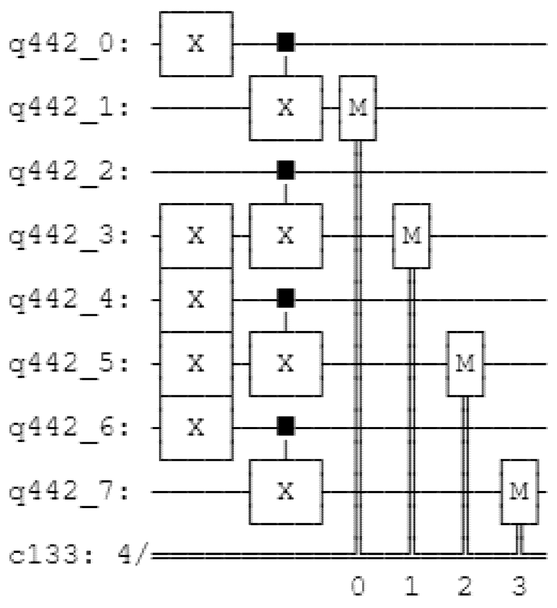
Descriptions 1 to 4 below describe Figure 16.
- Initialize qubit’s initial state to |0>.
- Calculate from the last digit (fourth) of the input values. The last digit of Input1 is 1, while that of Input2 is 0; hence, qubit_0 should be |1>, and qubit_1 should be |0>. Apply the Pauli-X gate to qubit_0 [4].
- The CNOT gate returns the result value in qubit_1, unlike 4.3.1 and 4.3.2. The XOR operation results are returned when it performs a measurement after applying the CNOT gate.
- Iterate this process for each digit.
4.3.4. Performance Evaluation
Multiple file units (e.g., KB, MB, and GB) are used by companies. The AES reads 128 bits (16 bytes) each; hence, it randomly gives input values repeatedly to mimic the encryption of multiple files.
AES-128 reads 16 bytes each and encrypts them, thus it becomes “Iteration = File Size (Byte)/16 (Byte).” Therefore, we can see the iteration according to the file size in Table 4. The experiment was conducted with AES-128 implemented in Python and Qiskit. The time unit was set to minutes. AES-128 in classical computing is implemented in Python because Qiskit consists of Python.
Table 5 shows the performance time for each platform. The performance time showed many variances. In the case of Qiskit, it took a long time to perform as much as each file size. Therefore, we calculated the number of iterations conducted was equal to the file size, based on the time spent per iteration. However, to measure the time taken for the performance comparison would be meaningless, because quantum computing was executed on a simulation basis. The quantum resource estimation would be a fairer comparison.
Table 6 presents the quantum resource estimation per iteration. “Gate” is the number of quantum gates used in the quantum circuit. “Width” is the number of qubits used plus the number of classical bits in the quantum circuit. “Depth” is the length of the critical path in the quantum circuit. “Qubit” is the number of qubits used in the quantum circuit. We plan to investigate a more accurate performance evaluation through quantum resource estimation analysis as an ongoing research.
5. Enhancement of Security
Shift Row is included in the AES algorithm analysis in Section 4.1. The encryption algorithm determines the number of bytes that should be shifted in each row of a matrix by a certain number, determined by the encryption algorithm. Anyone can descript Shift Row (=Inverse Shift Row) since it changes the bytes of each row of the matrix to a given integer. Because one of the decryption processes, inverse shift row, proceeds in the opposite direction of the Shift Row process.
Therefore, in this paper, unlike the existing algorithm, random numbers are generated so that the decryption method is not easily known, and rows can be moved according to the generated random numbers. The security of the system was improved by making the decryption method difficult to predict. We generated random numbers in three ways.
5.1. Linear Congruential Generator
The linear congruential generator is a widely known pseudo-random number generator. Multiply the value of the pseudo-random by a time, add c, divide by m, and choose the next pseudo-random. The linear congruential generator is defined in Equation (1).
X0 refers to the seed values. The generated random number depends on the seed value. However, the linear congruential generator has a maximum number of modulate operations available, and no more periods are available. For example, the maximum period value for a 64-bit machine is 264.
However, random numbers are generated within that period; hence, the smaller the period, the narrower the range of the random numbers generated, making it easier to predict the random numbers. In addition, the linear congruential generator has uniform random number distributions when expressed in one dimension, but not uniform when expressed in the n-dimension, consequently resulting in patterns.
For example, let n be 3 and the random numbers generated by the linear congruential generator be r1, r2, r3, … and rn. The following is defined to express the random numbers generated in three dimensions:
This has the disadvantage of being able to predict, to some extent, the random numbers generated by the occurring pattern.
5.2. Mersenne Twister
The Mersenne Twister [5] is a pseudo-random number generation algorithm created by Makoto Matsumoto and Takuji Nishimura. It is used in several programs, including C++, Excel, MATLAB, Python, and R and generates random numbers using 624 numbers.
The Mersenne Twister uses MT19937 with a random repetition period of 219,937 − 1 and MT19937-64 with 64 bits. This repetition period is the Mersenne prime, which is the number of the Mersenne prime that is the minority of Mersenne number. As you can see from Equation (2), the Mersenne number is a number from the power of two minus one.
The random numbers generated by the Mersenne Twister have a uniform distribution up to 623 dimensions unlike the linear congruential generator. In other words, finding a pattern is difficult, even if a coordinate corresponding to a 623-dimensional hypercube is paired with a random number of 623.
However, the Mersenne Twister also has the disadvantage of being able to predict the current state or the subsequent random numbers with only a finite number of random numbers knowing their period and range.
5.3. Quantum Random Walk
Quantum random walks are the quantum analog of the classical random walks [6]. Quantum random walks [7] execute coin operator and shift operator. The coin operator works by performing an arbitrary unitary transformation in the coin space, which creates a rotation similar to the “coin-flip” in a classical random walk. We use the Hadamard gate (Equation (3)) to execute the coin function because it puts qubits in a state of superposition, allowing for the simulation of a coin-based probability.
The shift operator acts with the coin operator, with unitary gates that combine the probability amplitudes with individual subnodes under each node.
Quantum random walks are studied as continuous- and discrete-time quantum random walks. However, we use herein the discrete-time quantum random walk because we need values to randomize the Shift Row.
The unitary operations in the discrete-time quantum random walk are made of coin and shift operators U = SC that work in a state space. The total state of the system is defined by the Hilbert space as follows:
where Hc is the coin Hilbert space, and Hp is the position Hilbert space. A coin-flip defines the direction in which the particle moves. A subsequent position shift operation moves the particle in the position space. We conducted a quantum random walk on a circular graph and implemented it on the quantum circuit [8].
H = Hc ⊗ Hp
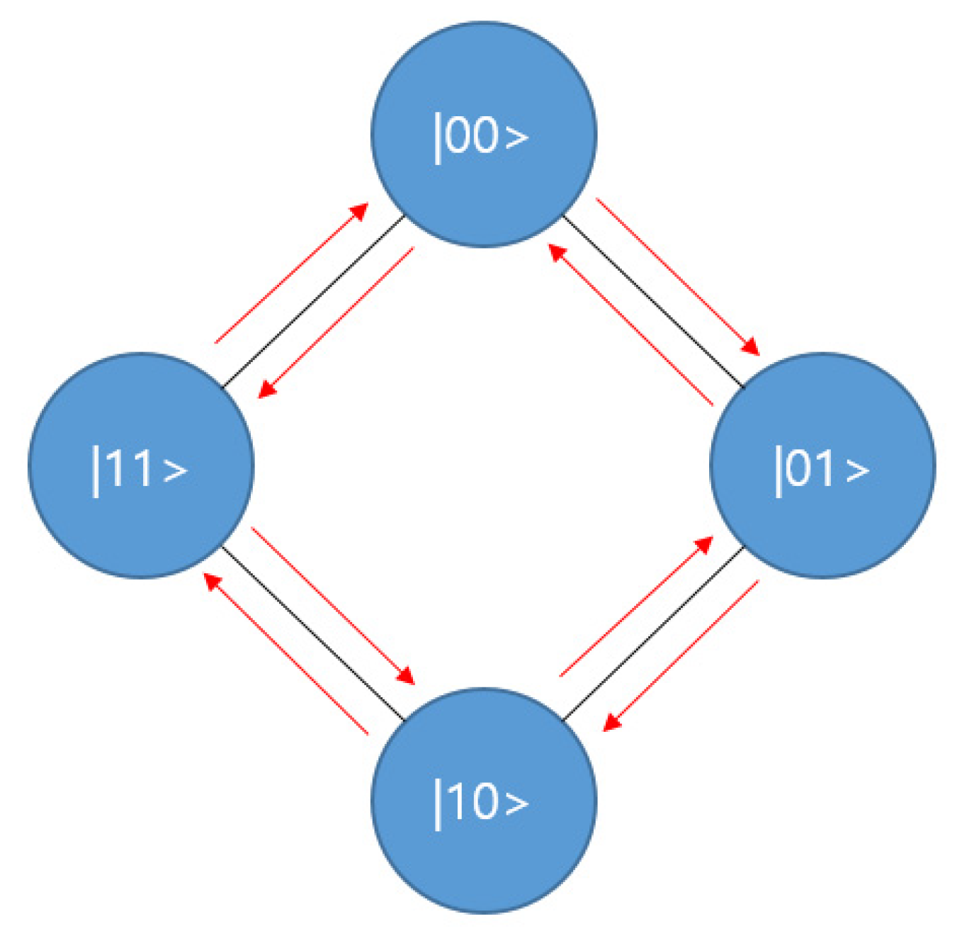
Figure 17 shows the whole process of the quantum random walk on a circular graph with 22 nodes (Figure 18). The gray rectangular frame means a set of coin and shift operators. In this circuit, q[0] and q[1] represent the state of the quantum walker, and q[2] represents the coin operator.
The coin operator decides whether the walker proceeds clockwise or counterclockwise. The INC is the gate that increments the walker state, which is equal to a clockwise rotation in the cycle graph. The DEC is the gate that decrements the walker state, which is equal to a counterclockwise rotation in the cycle graph.
After repeatedly executing the coin and shift(INC, DEC) operators, we can now know the probability of measuring a qubit and the walker position.
Figure 19 shows the probability that the qubit will be measured according to each value. However, a high probability value does not necessarily result in a measurement (=not an output value), and a low probability value can also be an output value.
Random numbers generated using quantum random walk have no repetitive cycles, so there is no correlation between the front and rear numbers, and are unpredictable because they depend on the probability. Therefore, we enhanced security by making estimation of decryption more difficult using quantum random walk.
6. Encryption Evaluation
In this study, we conducted a performance evaluation of images with encryption described in Section 5. We used Python to implement the original AES. Moreover, we proposed a method using the linear congruential generator and the Mersenne Twister using the systems and simulators provided by IBM Quantum using IBM Quantum accounts to implement the proposed method through the quantum random walk.
The experiments were conducted in quantum simulators because the AES proposed in this research is challenging to implement the existing quantum computing environment due to practical restrictions. In addition, IBM quantum computing environments support Qiskit, a quantum programming tool used in this study. However, IBM quantum computing environments with more than six qubits are currently exclusively used collaborative support for joint development. Because the AES described in this research requires more than six qubits, it is practically unavailable to quantum computing environments, so simulation results are reported. Lena, Baboon, and Pepper, which are 256 × 256 pixels, are the plain images shown.
The images in the first row in Figure 20 are plain images; those in the second row are cipher images; and those in the third row are the recovered images from the cipher images.
We used the number of pixel change rate (NPCR) and the unified average changing intensity (UACI) to test the influence of a 1 px change on the whole image encrypted by any encryption algorithm. The higher the NPCR and UACI values, the better the encryption will be.
6.1. Number of Pixels Change Rate
The NPCR [9] is a test used to measure the avalanche effect in image encryption. The avalanche effect is utilized to test the diffusion mechanism efficiency. A single bit change can be made in image P1 to give a modified image, P2. Both P1 and P2 are encrypted to give C1 and C2, respectively. The NPCR is defined as follows:
where D(i,j) is defined in Equation (6). The ciphertext images before and after 1 px change in a plaintext image are defined as C1 and C2. The pixel values at grid (i,j) in C1 and C2 are described as C1(i,j) and C2(i,j), respectively. M and N are the dimensions of the image to be encrypted.
6.2. Unified Average Changing Intensity
The UACI [10] measures the average intensity of the differences between two images and is defined as
where C1(i,j), C2(i,j), M, and N are the same as those in the NPCR described above.
We performed plain image sensitivity analysis through changing 1 px of random location for each experiment for plain images Lena, Baboon, and Pepper, and then calculating NPCR and UACI for all pixels. In addition, 10 experiments were conducted each in plain images of Lena, Baboon, and Pepper, and the results of NPCR and UACI for the plain images are shown in Table 7 and Table 8. The average NPCR was higher 99% and the average UACI was higher 33%.
This means that, even with a slight difference between the two plain images, the two encrypted images are completely different, and the results show that the proposed algorithm is highly sensitive to small changes in the plain image. Thus, the proposed algorithm indicates that it is robust against differential attacks. Differential attack refers to slightly changing the encrypted image (ex: modifying only 1 px) to observe the change in the result, thereby finding a meaningful relationship between the plain image and the encrypted image. However, differential attacks become useless if minor changes in plain images can cause significant changes in encrypted images. Therefore, it can be seen that the algorithm proposed in this paper has improved security compared to the existing algorithm.
Table 9 shows the performance time of the original AES algorithm and the proposed AES algorithm and the time uni. Compared to the existing AES method, the part that increased time complexity is the part that generated random numbers through quantum simulators. Encrypting an image with Original AES took 0.05 min, and 0.05 to 0.07 min to encrypt an image by generating random numbers with the Linear Consequential Generator and Mersenne Twitter. However, the time spent using quantum random walk using the quantum simulator may seem to have increased significantly to about 53–55 min, but this is time-consuming because random numbers were generated in the quantum simulator.
We implemented quantum random walk through quantum superposition using Hadamard gate, which takes a long time to derive computational values assuming that quantum superposed. However, in real quantum computers, quantum computers are performed by directly superposing them, so if quantum computers become common in the future, it will reduce the time required and will not be a big problem.
7. Conclusions and Future Work
In this paper, we proposed quantum computing-based implementations of existing AES algorithms and modified AES and described their performance evaluation.
Our results showed that the quantum computing-based implementation requires approximately 7518 gates and 64 qubits per iteration and the proposed algorithms generally showed good performance. Among them, the quantum random walk method showed the best encryption performance. We also used IBM Quantum accounts to use the systems and the simulators provided by IBM Quantum to implement the proposed method by a quantum random walk.
This research is in progress, thus further investigation into resource consumption and endeavors to reduce resource consumption will continue. Regarding evaluation on real quantum computers, as of now there are only 65 qubits of the latest quantum computers that can be accessed through the IBM Cloud. However, IBM recently announced plans to release the 1121-qubit system by the end of 2023 [11]. Once this system is released, we will compare the simulation results in the paper with those on real quantum computers. We will use quantum superposition to improve the speed side.
Author Contributions
Conceptualization, K.-K.K. and E.-S.J.; methodology, K.-K.K. and E.-S.J.; software, K.-K.K.; validation, K.-K.K. and E.-S.J.; formal analysis, K.-K.K. and E.-S.J.; investigation, K.-K.K.; resources, K.-K.K. and E.-S.J.; writing—original draft preparation, K.-K.K.; writing—review and editing, E.-S.J.; supervision, E.-S.J.; project administration, E.-S.J.; funding acquisition, E.-S.J. All authors have read and agreed to the published version of the manuscript.
Funding
This research was funded by the Ministry of Education (MOE) of Korea and the National Research Foundation (NRF) of Korea, BK21 FOUR.
Institutional Review Board Statement
Not applicable.
Informed Consent Statement
Not applicable.
Acknowledgments
This research was supported by the BK21 FOUR (Fostering Outstanding Universities for Research) funded by the Ministry of Education (MOE) of Korea and the National Research Foundation (NRF) of Korea.
Conflicts of Interest
The authors declare no conflict of interest.
References
- Sepherd, Inc. Available online: www.sepherd.kr/ (accessed on 11 August 2021).
- Morsch, O. Quantum Bits and Quantum Secrets: How Quantum Physics Is Revolutionizing Codes and Computers; John Wiley & Sons: Hoboken, NJ, USA, 2008; pp. 85–101. [Google Scholar]
- Mermin, N.D. From Cbits to Qbits: Teaching Computer Scientists Quantum Mechanics. Am. J. Phys. 2003, 71, 23–30. [Google Scholar] [CrossRef] [Green Version]
- Silva, V. Practical Quantum Computing for Developers: Programming Quantum Rigs in the Cloud Using Python, Quantum Assembly Language and IBM QExperience; Apress: New York, NY, USA, 2018; pp. 154–203. [Google Scholar]
- Matsumoto, M.; Nishimura, T. Mersenne Twister: A 623-Dimensionally Equidistributed Uniform Pseudo-Random Number Generator. ACM Trans. Model. Comput. Simul. 1998, 8, 3–30. [Google Scholar] [CrossRef] [Green Version]
- Travaglione, B.C.; Milburn, G.J. Implementing the quantum random walk. Phys. Rev. A 2002, 65, 032310. [Google Scholar] [CrossRef] [Green Version]
- Aharonov, Y.; Davidovich, L.; Zagury, N. Quantum random walks. Phys. Rev. A 1993, 48, 1687–1690. [Google Scholar] [CrossRef] [PubMed]
- Khan, M.M.M.; Biswas, A.K.; Chowdhury, S.; Hasan, M.; Khan, A.I. Synthesis of GF(3) based Reversible/Quantum Logic Circuits Without Garbage Output. In Proceedings of the 39th International Symposium on Multiple-Valued Logic, Naha, Japan, 21–23 May 2009; pp. 98–102. [Google Scholar]
- El-Samie, F.E.A.; Ahmed, H.E.H.; Elashry, I.F.; Shahieen, M.H.; Faragallah, O.S.; El-Rabaie, E.-S.M.; Alshebeili, S.A. Image Encryption: A Communication Perspective; CRC Press: Boca Raton, FL, USA, 2017; pp. 33–38. [Google Scholar]
- Wu, Y.; Noonan, J.P.; Agaian, S. NPCR and UACI Randomness Tests Image Encryption. J. Sel. Areas Telecommun. 2011, 1, 31–38. [Google Scholar]
- IBM Quantum Computing Roadmap. Available online: https://research.ibm.com/blog/ibm-quantum-roadmap (accessed on 30 August 2021).
Figure 1.
Architecture of the existing file encryption system.

Figure 2.
AES-128 encryption/decryption algorithm.

Figure 3.
Qubit.

Figure 4.
S-box table.

Figure 5.
Shift Row.

Figure 6.
Rcon table.

Figure 7.
Classical AND gate.

Figure 8.
Toffoli gate.

Figure 9.
Classical OR gate.

Figure 10.
Classical NOT gate.

Figure 11.
Pauli-X gate.

Figure 12.
Classical XOR gate.

Figure 13.
CNOT gate.

Figure 14.
Classical AND gate using the Toffoli gate.

Figure 15.
Classical OR gate using the Pauli-X and Toffoli gates.

Figure 16.
Classical XOR gate using the CNOT gate.

Figure 17.
Quantum random walk on a circular graph.

Figure 18.
Circuit with an implemented quantum random walk.

Figure 19.
Result of quantum random walk.

Figure 20.
Result of the encryption/decryption using the proposed methods.


Table 1.
AND Gate vs. Toffoli Gate.
| Input | Output | |||||
|---|---|---|---|---|---|---|
| A | B | C | A | B | A·B | |
| AND (classical) | 0 | 0 | X | X | X | 0 |
| 0 | 1 | X | X | X | 0 | |
| 1 | 0 | X | X | X | 0 | |
| 1 | 1 | X | X | X | 1 | |
| Toffoli (quantum) | 0 | 0 | 0 | 0 | 0 | 0 |
| 0 | 1 | 0 | 0 | 1 | 0 | |
| 1 | 0 | 0 | 1 | 0 | 0 | |
| 1 | 1 | 0 | 1 | 1 | 1 | |
Table 2.
NOT Gate vs. Pauli-X Gate.
| Input | Output | |
|---|---|---|
| NOT (classical) | 0 | 1 |
| 1 | 0 | |
| Pauli-X (quantum) | 0 | 1 |
| 1 | 0 |
Table 3.
XOR Gate vs. CNOT Gate.
| Input | Output | |||
|---|---|---|---|---|
| A | B | A | A ⊕ B | |
| XOR (classical) | 0 | 0 | X | 0 |
| 0 | 1 | X | 1 | |
| 1 | 0 | X | 1 | |
| 1 | 1 | X | 0 | |
| CNOT (quantum) | 0 | 0 | 0 | 0 |
| 0 | 1 | 0 | 1 | |
| 1 | 0 | 1 | 1 | |
| 1 | 1 | 1 | 0 | |
Table 4.
Iteration by file size.
| File Size | Byte | Iteration |
|---|---|---|
| 500 KB | 512,000 | 32,000 |
| 100 MB | 104,857,600 | 6,553,600 |
| 0.5 G | 536,870,912 | 33,554,432 |
| 1 G | 1,073,741,824 | 67,108,864 |
Table 5.
Performance time.
| File Size | Python | Qiskit |
|---|---|---|
| 500 KB | 0.07 | 715,968 (estimated) |
| 100 MB | 14.12 | 147,458,110 (estimated) |
| 0.5 G | 72.77 | 739,875,225 (estimated) |
| 1 G | 146.73 | 1,479,750,448 (estimated) |
Table 6.
Quantum resource estimation per iteration.
| Total | Resources |
|---|---|
| Gates | 7518 |
| Depth | 3452 |
| Width | 96 |
| Qubits | 64 |
Table 7.
NPCR result of the original AES and the proposed methods.
| NPCR (%) | |||||
|---|---|---|---|---|---|
| Image (256 × 256) | Color Channel | Original AES | Method by the LCG | Method by the MT | Method by the QRW |
| Lena | R | 0.0079 | 99.5883 | 99.601 | 99.6214 |
| G | 0.0082 | 99.5972 | 99.588 | 99.6001 | |
| B | 0.0081 | 99.5903 | 99.6222 | 99.6053 | |
| Baboon | R | 0.0081 | 99.6012 | 99.6201 | 99.6144 |
| G | 0.0081 | 99.6097 | 99.6114 | 99.6196 | |
| B | 0.0082 | 99.6105 | 99.6063 | 99.6077 | |
| Pepper | R | 0.0081 | 99.5899 | 99.5972 | 99.5929 |
| G | 0.0079 | 99.5933 | 99.6104 | 99.5944 | |
| B | 0.0081 | 99.6016 | 99.6018 | 99.6022 | |
Table 8.
UACI result of the original AES and the proposed methods.
| NPCR (%) | |||||
|---|---|---|---|---|---|
| Image (256 × 256) | Color Channel | Original AES | Method by the LCG | Method by the MT | Method by the QRW |
| Lena | R | 0.0029 | 33.4453 | 33.451 | 33.4648 |
| G | 0.0026 | 33.4366 | 33.4935 | 33.4796 | |
| B | 0.0028 | 33.3944 | 33.456 | 33.4287 | |
| Baboon | R | 0.0027 | 33.4097 | 33.4058 | 33.4803 |
| G | 0.003 | 33.4201 | 33.4408 | 33.4448 | |
| B | 0.0024 | 33.4096 | 33.4115 | 33.4726 | |
| Pepper | R | 0.0029 | 33.4744 | 33.4787 | 33.4774 |
| G | 0.0029 | 33.4134 | 33.4216 | 33.4609 | |
| B | 0.0028 | 33.4386 | 33.4553 | 33.4736 | |
Table 9.
The performance time of the proposed algorithm.
| Image (256 × 256) | Original AES | Method by the LCG | Method by the MT | Method by the QRW |
|---|---|---|---|---|
| Lena | 0.05 | 0.06 | 0.05 | 53.256 |
| Baboon | 0.04 | 0.06 | 0.06 | 55.729 |
| Pepper | 0.05 | 0.05 | 0.07 | 54.481 |
Publisher’s Note: MDPI stays neutral with regard to jurisdictional claims in published maps and institutional affiliations. |
© 2021 by the authors. Licensee MDPI, Basel, Switzerland. This article is an open access article distributed under the terms and conditions of the Creative Commons Attribution (CC BY) license (https://creativecommons.org/licenses/by/4.0/).
Share and Cite
MDPI and ACS Style
Ko, K.-K.; Jung, E.-S. Development of Cybersecurity Technology and Algorithm Based on Quantum Computing. Appl. Sci. 2021, 11, 9085. https://0-doi-org.brum.beds.ac.uk/10.3390/app11199085
AMA Style
Ko K-K, Jung E-S. Development of Cybersecurity Technology and Algorithm Based on Quantum Computing. Applied Sciences. 2021; 11(19):9085. https://0-doi-org.brum.beds.ac.uk/10.3390/app11199085
Chicago/Turabian StyleKo, Kyung-Kyu, and Eun-Sung Jung. 2021. "Development of Cybersecurity Technology and Algorithm Based on Quantum Computing" Applied Sciences 11, no. 19: 9085. https://0-doi-org.brum.beds.ac.uk/10.3390/app11199085
Note that from the first issue of 2016, this journal uses article numbers instead of page numbers. See further details here.