Article

Study on Soil Displacement Fields around the Expanded Body of Drill-Expanded Concrete Piles Based on DIC Technique

1
School of Transportation Science and Engineering, Jilin Jianzhu University, Changchun 130118, China
2
School of Civil Engineering, Jilin Jianzhu University, Changchun 130118, China
*
Authors to whom correspondence should be addressed.
Submission received: 30 August 2021 / Revised: 23 September 2021 / Accepted: 24 September 2021 / Published: 29 September 2021
(This article belongs to the Special Issue Recent Progress on Advanced Foundation Engineering)

Abstract

:
The soil displacement field around a drill-expanded concrete pile is noticeably different from that of an equivalent section pile placed under axial load due to the mutual embedment between the expanded body and the soil. It is important to study the soil displacement field around drill-expanded concrete piles in order to understand the mechanisms of interaction between the pile and the soil. First, the model test of the half-face pile installed in undisturbed soil and the model test of the half-face pile installed in sand were used to study the soil displacement field around the pile. Then, the entire process of the soil displacement field’s formation and development under the load was observed by using digital image correlation (DIC) techniques. Finally, numerical simulation was used to verify the results of the model tests. The results show that the displacement characteristics of the soil around the pile in the undisturbed soil and sand are basically the same. There is a clear soil compression zone under the expanded body, and the magnitude and density of the displaced soil in the compression zone are much higher than in other areas. Both the vertical displacement and the horizontal displacement gradually decrease as the distance from the expanded body and the burial depth increase. The horizontal displacement of the soil under the expanded body follows a trend of first moving toward the pile body and then moving away from it. The results of the numerical simulation are basically consistent with the results of the model test, indicating that the results of the model test are relatively reliable.

1. Introduction

The drill-expanded concrete pile is a new type of variable cross-section cast-in-place pile based on the expanded pile and which has one or more expanded bodies at the appropriate positions based on the ordinary straight-hole cast-in-place pile created by drilling and expanding equipment. Compared with regular expanded piles, drill-expanded concrete piles have better pile quality and less disturbance of the soil around the pile due to the difference in construction technology. The process of creating a drill-expanded concrete pile is shown in Figure 1. First, the forward rotation is used to start drilling (Figure 1a). When drilling to the specified position, the equipment is reversed to start the diameter expansion, and the drilling-expanding arm gradually expands to cut the soil around the hole wall (Figure 1b). When the diameter is expanded, the drill stops rotating and becomes a reliable support for the diameter expansion operation until the diameter expansion is completed (Figure 1c). Then, the equipment is switched to drilling mode, after which the next diameter expansion is carried out. Finally, the steel cage is placed, and the concrete is poured (Figure 1d). A photo of a real drill-expanded concrete pile is shown in Figure 1e. For drill-expanded concrete piles, the expanded body and the soil are mutually embedded, which can result in the complicated behavior of the interface between pile and soil. Studying the process of soil displacement around the drill-expanded concrete pile is important for improving the interaction between the soil and the pile and to ensuring the long-term safety and stability of the drill-expanded concrete piles used in high buildings, power transmission lines, highways, and large bridges. Improving our understanding of the entire process of soil deformation around the pile is an important step forward for the field.
The problem of the mechanics and deformation characteristics of the soil around the pile has been studied and discussed by many scholars using numerical simulation [1,2,3,4], theoretical model [5,6], and indoor physical test [7,8,9,10,11]. Due to better control of conditions and being more economically viable than in situ tests, physical model studies are being widely used in the study of the interaction between soil and expanded pile. Qian et al. [12,13] used indoor and on-site half-face pile models to obtain the load-bearing performance of a drill-expanded concrete pile under vertical and horizontal loads and analyzed the failure mode of the soil around the expanded pile. Fang et al. [14] simulated variable cross-section piles with extra-large diameters and assessed the effect of several factors on soil deformation characteristics through indoor model tests. Qing et al. [15] analyzed the soil deformation caused by expanded-base pile jacking with casing by particle image velocimetry (PIV). Ju and Chen [16] found that the compressive strength of concrete, the height-to-width ratio of the expanded plate, and the disc diameter ratio of the expanded plate were the major factors affecting the expanded plate’s bearing capacity by using the small-scale model test. However, the displacement value of the soil around the pile cannot be obtained in the traditional indoor physical test, and in the transparent soil test, the transparent soil cannot simulate types of soil. Therefore, it is necessary to find a test method that can not only use the real soil but also reflect the displacement of the soil around the pile.
The development of digital camera and computer analysis technologies enabled the subsequent development and improvement of digital image correlation (DIC) technology. DIC compares two images in order to determine the magnitude and direction of soil displacement. When two images undergo a displacement, the location of the peak of the correlation function determines the location of the best match between the two images, which corresponds to the magnitude and direction of the movement. If the entire image area is divided into numerous small interrogation windows, the displacement field can be obtained by calculating the displacement in each interrogation window [17]. DIC technology has been widely used in geotechnical engineering due to the advantage of allowing high precision and non-contact full-field strain measurement [18,19,20]. Using the DIC technique, Tovar-Valencia et al. [21] determined that an increase in the roughness of the shaft results in an increase in the average unit of shaft resistance and in displacements and strains in the soil next to the pile shaft. Cao et al. [22] determined the distributions of displacement during pile installations with different jacking depths, frictions, and pile shoes. By using an indoor half-face pile model test and DIC technology, Lu [23] was able to determine the law of soil displacement development around the pile during static pressure piling. Galvis-Castro et al. [24] used the digital image correlation technique to generate the displacement and strain fields of sand and determined that reversing the loading direction substantially reduced the units of shaft resistance, which was attributed to a drop in the radial strain exhibited by the soil elements surrounding the model pile shaft. Chen et al. [25] applied digital image correlation throughout the test to better examine the performance of screw–shaft piles. As previous work demonstrates, studying the deformation characteristics of the soil around a pile is important to the ongoing study of the interaction between piles and soil. In the current research, most of the soil used is transparent soil, and most of the research objects are traditional piles. The soil displacement characteristics around the drill-expanded concrete piles are relatively complex, and there are currently no systematic studies on this topic utilizing digital image correlation technology. The introduction of digital image correlation technology into the study of soil displacement fields around expanded bodies can provide valuable data to help reveal the mechanisms of pile–soil interactions.
This study involved tests of small-scale half-face piles in undisturbed soil and sand. The dynamic development process of the soil displacement field around the pile under vertical load was recorded by the VIC-3D non-contact full-field strain measurement system. The soil displacement field information was analyzed using digital image correlation (DIC) technology. The characteristics of the soil around the pile under load were described as they evolved during pile development. The model test was verified by numerical simulation, and the results of the numerical simulation are relatively consistent with those of the physical test. The novelty of this paper is to use the DIC technology to observe the horizontal and vertical displacements of the soil around the expanded body visually, and then the distribution characteristics of the soil around the pile were analyzed, which could provide a new method and idea to study the soil displacement characteristics around the pile and the mechanism of interaction between soil and pile.

2. Materials and Methods

2.1. Test Soil

Undisturbed soil and sand were used for testing and analysis. For indoor model tests, the following assumptions are made:
(1)
The impact of drilling and expanding on the soil around the pile during construction is not considered;
(2)
The non-uniformity of the disturbed soil around the pile is not considered.

2.1.1. Undisturbed Soil

The undisturbed soil used in this experiment was taken from at a depth of 1.5–2.0 m below a foundation pit in Changchun, China. It was clay with a yellowish-brown color, which is a common foundation soil in the Changchun area. The sampling process of the undisturbed soil in the indoor model test is shown in Figure 2. First, the site was excavated and leveled (Figure 2a), then the self-made soil sampler was placed at the designated position (Figure 2b), and the soil sampler was then pressed into the soil with mechanical equipment, including an excavator (Figure 2c). After the soil sampler was completely pressed into the soil, it was dug out (Figure 2d), the excess soil on the outer wall of the soil sampler was cleaned off (Figure 2e), and the soil sampler was sealed with a plastic cloth for standby use and to preserve its moisture content (Figure 2f). The particle size distribution curve, as measured by the BT-9300LD laser particle size distribution analyzer, is shown in Figure 3. The XRD test was carried out using an X-ray diffractometer (PANalytical B.V., Almelo, The Netherlands) to measure the primary mineral components of the soil. The results of the XRD test results are given in Figure 3. The main mineral components of the soil used in the test were quartz, albite, and K-feldspar. The basic physical properties were measured using a geotechnical test, and the results are shown in Table 1.

2.1.2. Sand

The white quartz sand was used as the test soil, which had a hardness of 7, the particle size was 0.425 to 0.85 mm, and the property parameters are shown in Table 2. Black quartz sand was used as the surface speckle material, with a hardness of 7 and a particle size of 2 to 3 mm.

2.2. Model Pile

The model pile is a half-circular steel rod with a diameter of 17 mm and a length of 266 mm (Figure 4a). The expanded body has a diameter of 58 mm, a height of 28 mm, and a slope foot of 35°. The embedding process of the pile in the undisturbed soil is shown in Figure 4b. The undisturbed soil samples retrieved from the site were surface leveled, the model pile was positioned on the soil surface, and then the soil surface was excavated according to the positioning and dug according to the expanded body size of the model pile. Finally, the model pile was gently placed in the soil and constantly trimmed to ensure that there was neither a cavity nor over-extrusion between the model pile and the soil. The embedding process of the pile in the sand is shown in Figure 4c. First, the model pile was placed in a self-made loading box. Then, black sand and white sand were layered and placed in the loading box. After loading and compaction, it was ready to be tested.

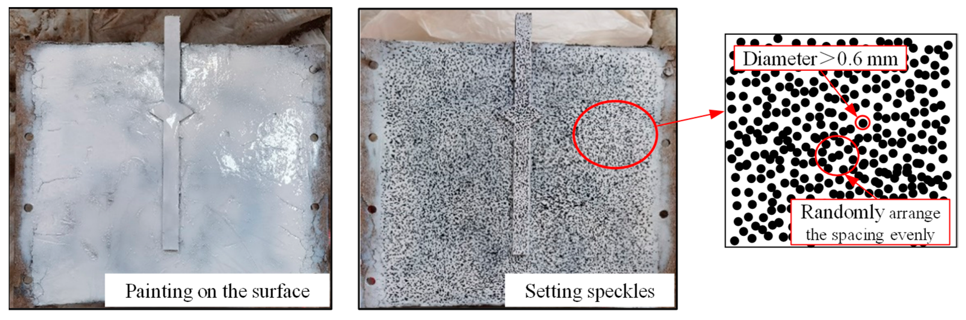
2.3. Painting Preparation for Undisturbed Soil

Since the black sand is set as the scattered spots, the sand does not need to be painted. The undisturbed soil particles are yellow clayey soil, with fine soil particles and no significant texture. To enable subsequent digital image processing, white paint was uniformly sprayed on the collection surface. After the white paint was slightly dry, black speckles were attached to the white paint surface in order to acquire the displacement characteristics of the collected surface soil, as shown in Figure 5. The size of the experimental shooting area was approximately 48 × 36 mm, and the diameter of the scattered points was set to be greater than 0.6 mm. The soil contained water, and the white paint sprayed on the surface was extremely thin, with a thickness of only micrometers. The white paint could thus adhere to the soil surface and maintain consistency with the soil deformation, and its influence on the test results was negligible.

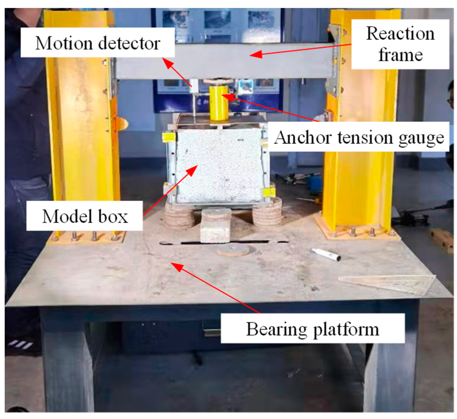
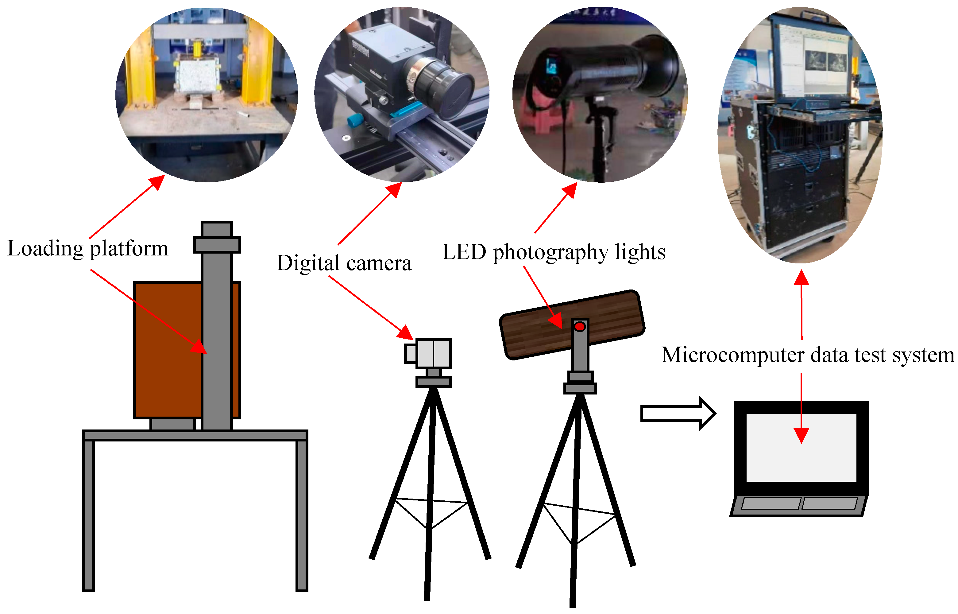
2.4. Experiment Equipment

The loading process employed a loading platform developed by the project team. As shown in Figure 6, the loading platform consisted of a bearing platform, a reaction frame, a ZY anchor rod tension gauge, and a YHD-100 displacement sensor. The camera system was a VIC-3D non-contact full-field strain measurement system provided by Correlated Solutions Inc., the United States. As shown in Figure 7, the test system consists of a VIC-3D measuring head, an LED-2000 photoflood lamp, a tripod, and a microcomputer test system. The digital camera was fixed in front of the acquisition surface, the VIC-3D measuring head had 12.3 million pixels, the resolution was 4096 × 3000 pixels, the sub-area size was 33 pixels, the step size was 8 pixels, the sub-area size was set to approximately 3.795 × 2.846 pixels, and the photographic speed was 1 frame/250 ms. To obtain uniform lighting, an LED-2000 photoflood lamp was arranged directly in front of the collection surface.

3. Digital Image Correlation (DIC) Technology

Digital image correlation (DIC) technology is a non-contact full-field measurement technology, which determines displacement and deformation based on the correlation of the speckle image on the material surface before and after the deformation occurs. Digital image correlation technology can be used to analyze the deformation characteristics of the rock and soil test models and can then study the whole process of the displacement and failure of soil around a pile. In the present experiment, DIC technology was used to analyze the acquired images. The basic principle is to adopt a cross-correlation method in order to expose objects in different motion states at two times and image them on two different pictures. By dividing the image into square sub-areas of suitable size, it is possible to compare the gray-scale feature values of these sub-areas, identify the correlational relationships between specific sub-areas, calculate the displacement of pixels, and thus, access local displacement field data. After completing the analysis of the entire study area, the overall strain and displacement field distribution information is obtained, which is then visually expressed in the form of images [17,26].
We assume that the gray-scale feature functions of the two digital images before and after the deformation are f(x, y) and g(x′, y′), where, x, y and x′, y′ are the positions of a certain pixel before and after the deformation. We use u and v to denote the displacement components of the feature point along the x and y directions. Then:
x = x + u + u x Δ x + u y Δ y
y = y + v + v x Δ x + v y Δ y
After obtaining the gray distribution of the two sub-areas before and after the deformation, the correlation coefficient is used as the standard for evaluating the similarity between the two sub-areas. The correlation coefficient C is defined as:
C = f ( x , y ) g ( x , y ) [ f 2 ( x , y ) g 2 ( x , y ) ] 1 2
In the formula, f and g are the gray-scale feature values of a certain sub-area before and after deformation. When C = 1, the two sub-area are fully correlated; when C = 0, the two sub-areas have no correlation.
Based on the above principles, the built-in DIC analysis software of the VIC-3D non-contact full-field strain measurement system was used to analyze and process the collected images. It was also used to obtain other relevant information, such as the plane displacement field and the displacement of each point.

4. Results and Discussion

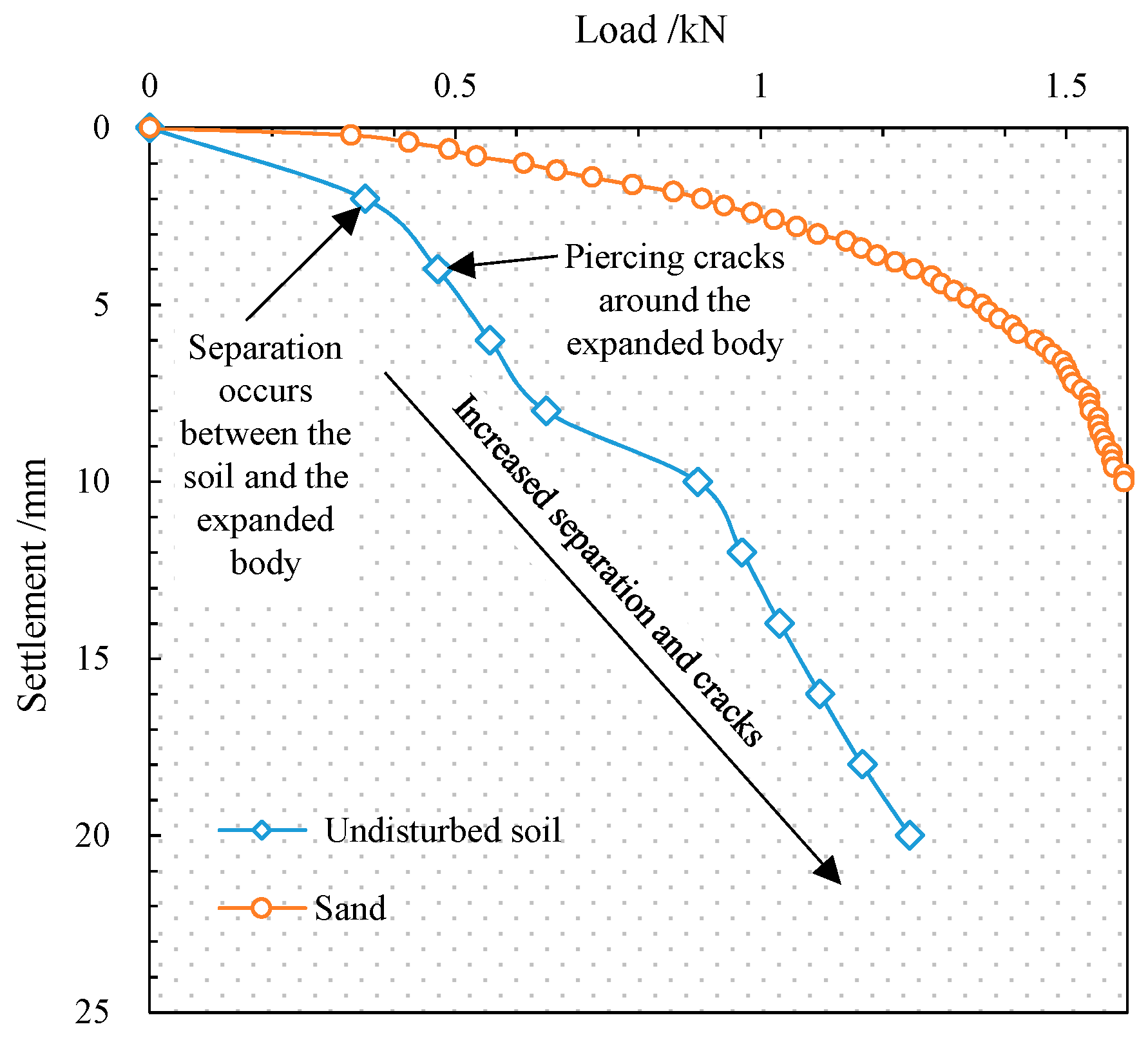
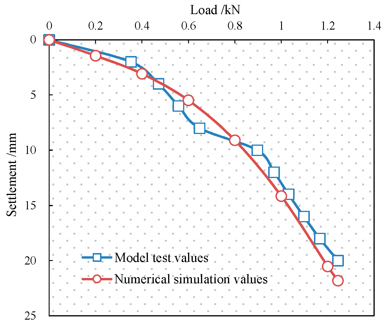
4.1. Load–Settlement Curve

The ZY anchor rod tension gauge was used for manual loading via the displacement control method. That is, for every additional displacement of the pile top (2 mm for undisturbed soil and 0.2 mm for sand), the load value was recorded once, and loads ranging from 0 to 1.224 kN for undisturbed soil and 0 to 1.595 kN for sand were applied. The load-settlement curve obtained through the test is shown in Figure 8.
Figure 8 demonstrates that, as the load increases, the pile top displacement gradually increases as well. For the pile in the undisturbed soil, there are roughly four stages between the start of the loading and the end of the process. The first stage is the initial loading stage (from 0 to 0.352 kN). As the model pile moves downward, the single pile bearing force is borne by the soil around the pile, the soil under the expanded body, and the soil at the end of the pile. At this time, the load is small, so the load–displacement curve changes slightly. In the second stage (from 0.352 to 0.648 kN), as the load continues to increase, the pile top displacement of the model keeps increasing, the soil above the expanded body separates from the pile body, and the frictional resistance between the pile and soil above the expanded body decreases and may even cease to play a role. At this time, the soil below the expanded body is compressed, and the load is borne by both the soil under the expanded body and the soil at the end of the pile. In the third stage (from 0.628 to 0.897 kN), due to the compression of the soil below the expanded body, its strength is improved, and the load-settlement curve changes slightly. In the fourth stage (from 0.897 to 1.244 kN), the load continues to increase, causing the slope of the load–displacement curve to steepen. For the pile in the sand, the curve of load and settlement of the pile top is relatively smooth. As the load increases, the displacement continues to increase, and there is no obvious stage division.

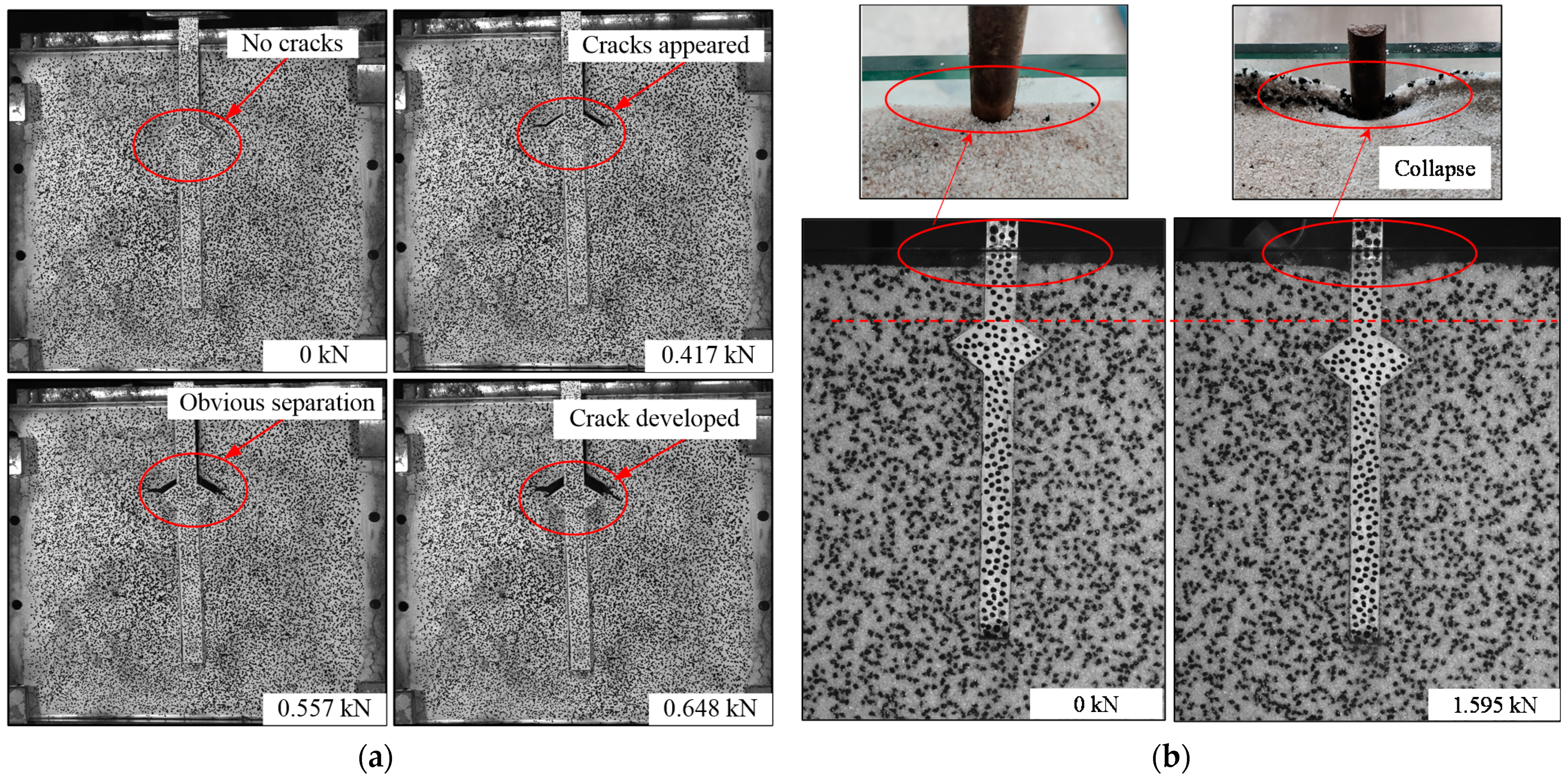
4.2. Pile–Soil Separation Characteristics

In the test, the failure process of the drill-expanded concrete pile and the soil was recorded throughout the entire loading process. Figure 9a shows the failure process of the undisturbed soil around the pile under different loads. At the beginning of the load application, the load was small, and no cracks appeared between the upper part of the expanded body and the soil. As the applied load increased, the model pile moved downwards, and the soil above the expanded body appeared to separate from the pile body. With the continuous increase in the load, the separation width and scope gradually increased as well. The separation became increasingly pronounced, and the cracks penetrated into the soil on either side along the upper edge of the expanded body. The crack depth gradually increased as the applied load increased. However, since the test utilized clayey soil and the entire loading period was short, the soil above the expanded body did not fall significantly. Figure 9b shows the failure process of the sand around the pile. For sand, as the load increases, there is no separation between the upper part of the expanded body and the sand. The sand moves downward with the pile, and at the same time, there is a phenomenon of downward collapse on the surface of the sand around the pile top.
Figure 10 is a schematic diagram of undisturbed soil cracking under force at the tip of the expanded body. Due to the unique features of drill-expanded concrete piles, cracks occur in the soil at the tip of the expanded body. When the pile is subjected to a downward load, the expanded body will exert downward pressure on the soil below it, and the soil at the tip of the expanded body will generate a strong crack propagation force (G) due to the stress concentration. The size of the crack propagation force is relative to the load applied to the pile. The soil at the tip of the expanded body possesses a crack propagations resistance (R). The crack propagation resistance is related to the soil properties, such as the soil’s cohesive force and the angle of its internal friction. Crack propagation resistance also relates to the soil’s stress state. When the crack propagation force exceeds the crack propagation resistance of the soil at the tip of the expanded body, the crack will propagate further and expand (Δa is the newly expanded crack length).

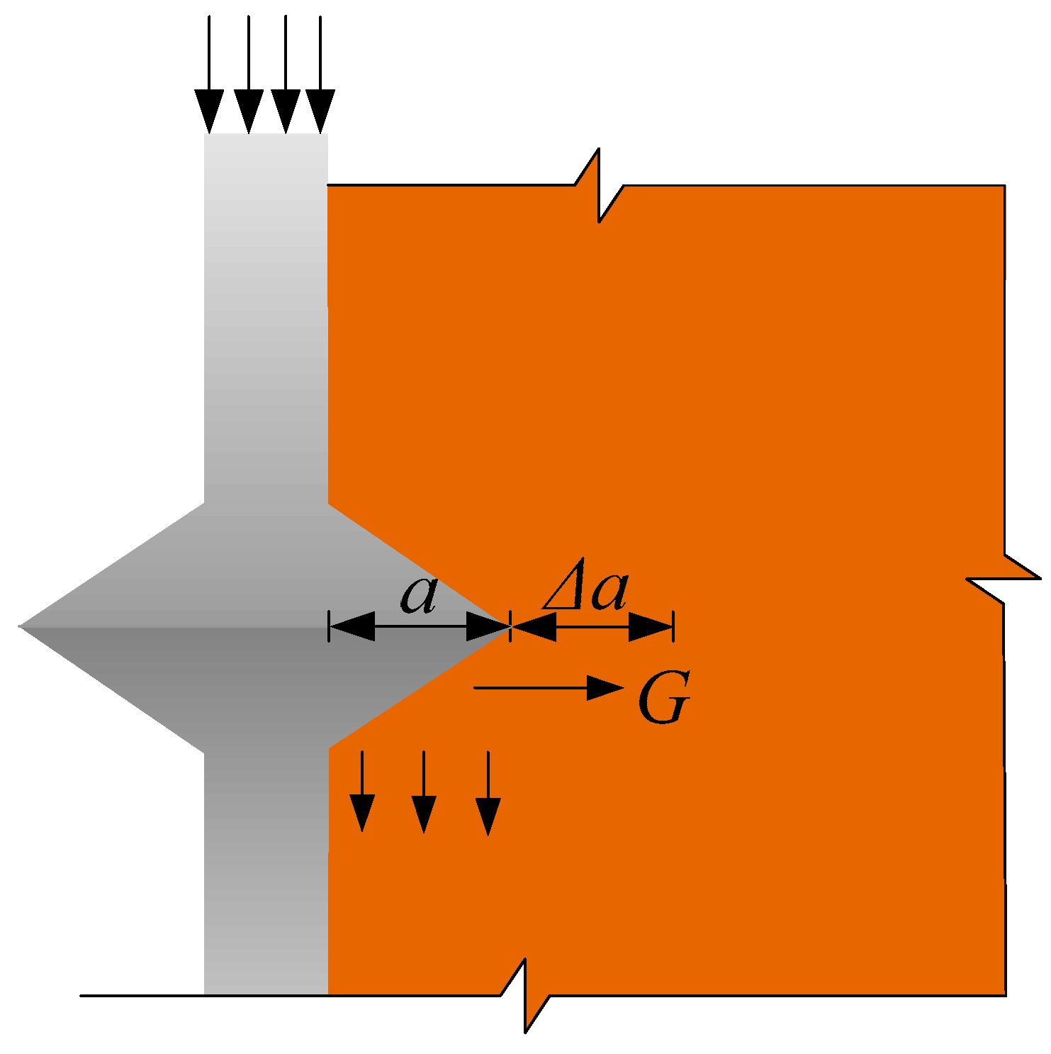
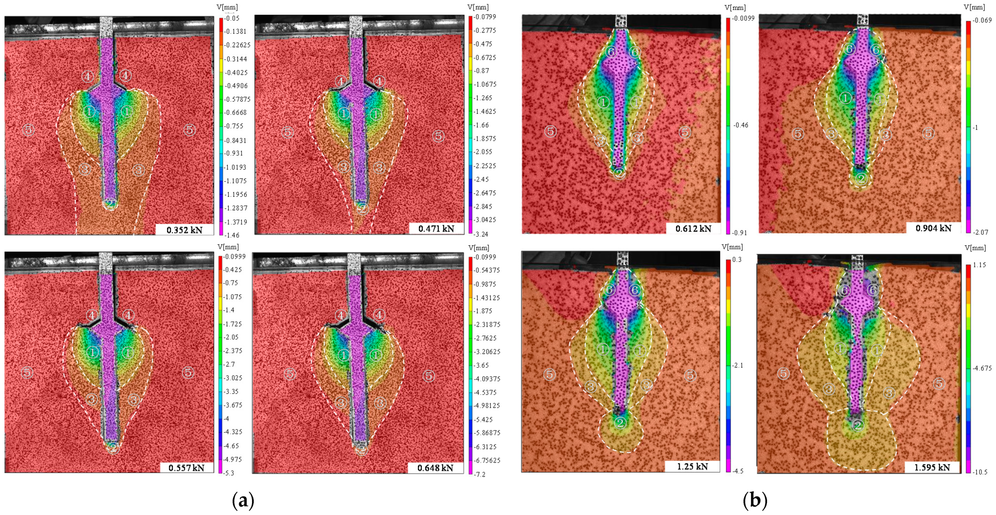
4.3. Soil Displacement Field around Expanded Body

Figure 11 is a cloud diagram of the vertical displacement field of the soil in the model box under the load, according to digital image correlation technology. The soil around the pile in Figure 11a is undisturbed soil, and Figure 11b is sand. It can be seen in Figure 11 that there is clear soil compression under the expanded body (area ①), i.e., that there is significant soil displacement in the compression zone, and the displacement magnitude and density of the soil in the compression zone are much higher compared to other areas. The range of soil compression under the expanded body (area ①) is about 0.5 times the diameter of the expanded body. The displacement occurs around the bottom of the expanded body and increases along its length, while in areas distant from the expanded body, there is only minor or negligible soil displacement. There is also a soil compression zone at the bottom of the pile (area ②). As the load increases, the extent of the compression zone gradually increases, with the degree of soil compression gradually increasing as well. There is a pile influence zone (area ③), and the range of it is about 1.2 times the diameter of the expanded body. Area ④ is a pile-soil separation zone in the undisturbed soil, area ⑥ is the area where the sand moves downward with the pile body in the sand and area ⑤ is the uninfluenced zone. It can be seen that the trend of displacement distribution and development in the sand are the same as in the undisturbed soil. However, there is no obvious separation area between the pile and the sand.

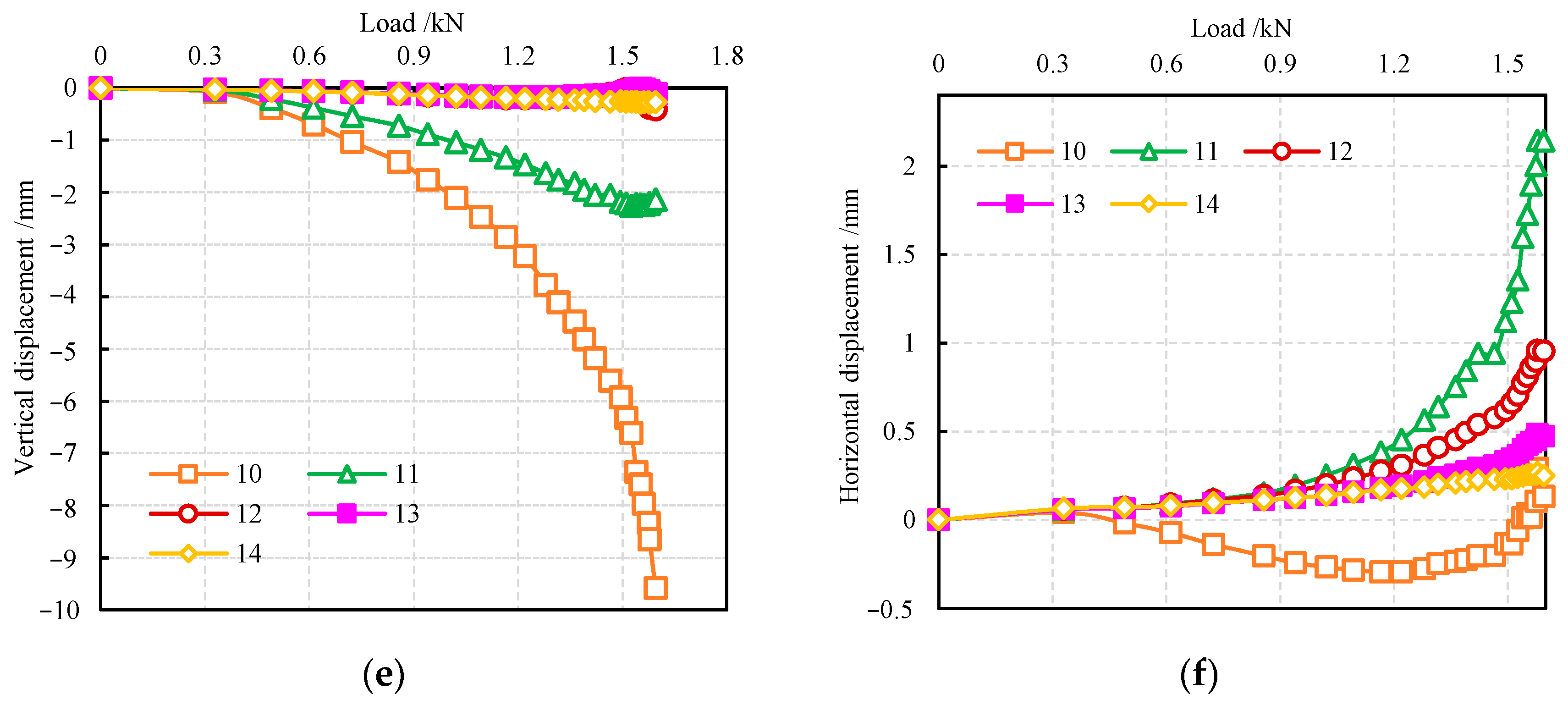
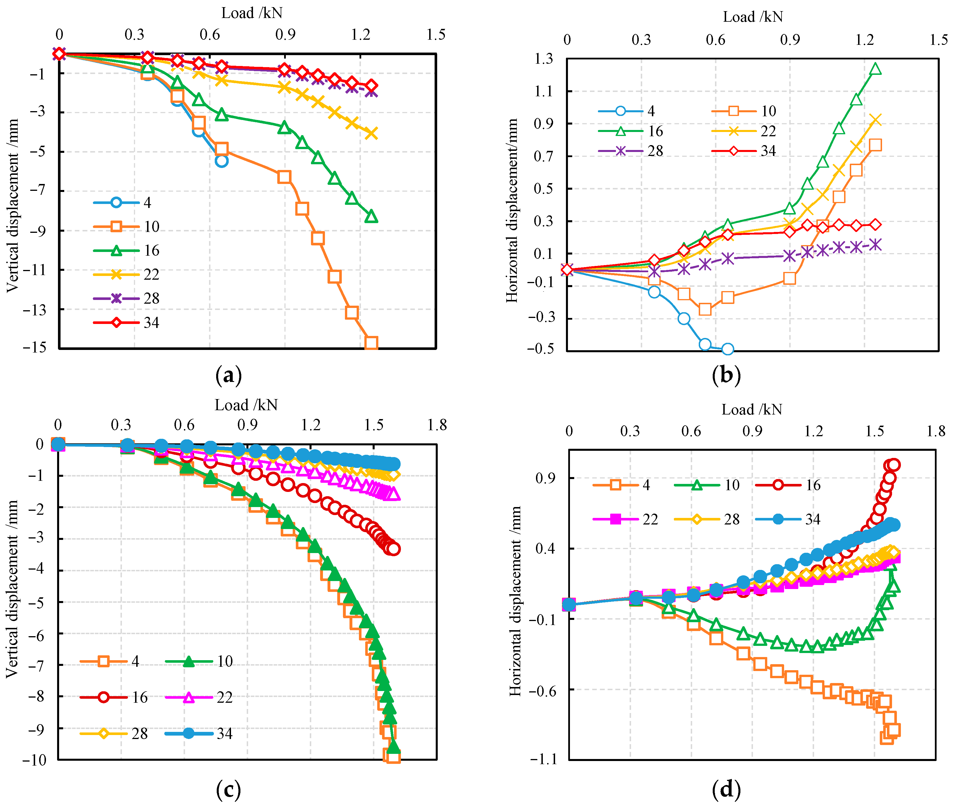
4.4. Relationship between Soil Displacement and Load around the Expanded Body

Data on the soil displacement with different load positions are analyzed in order to determine the displacement distribution of the soil around the pile. The specific data points are distributed as shown in Figure 12.

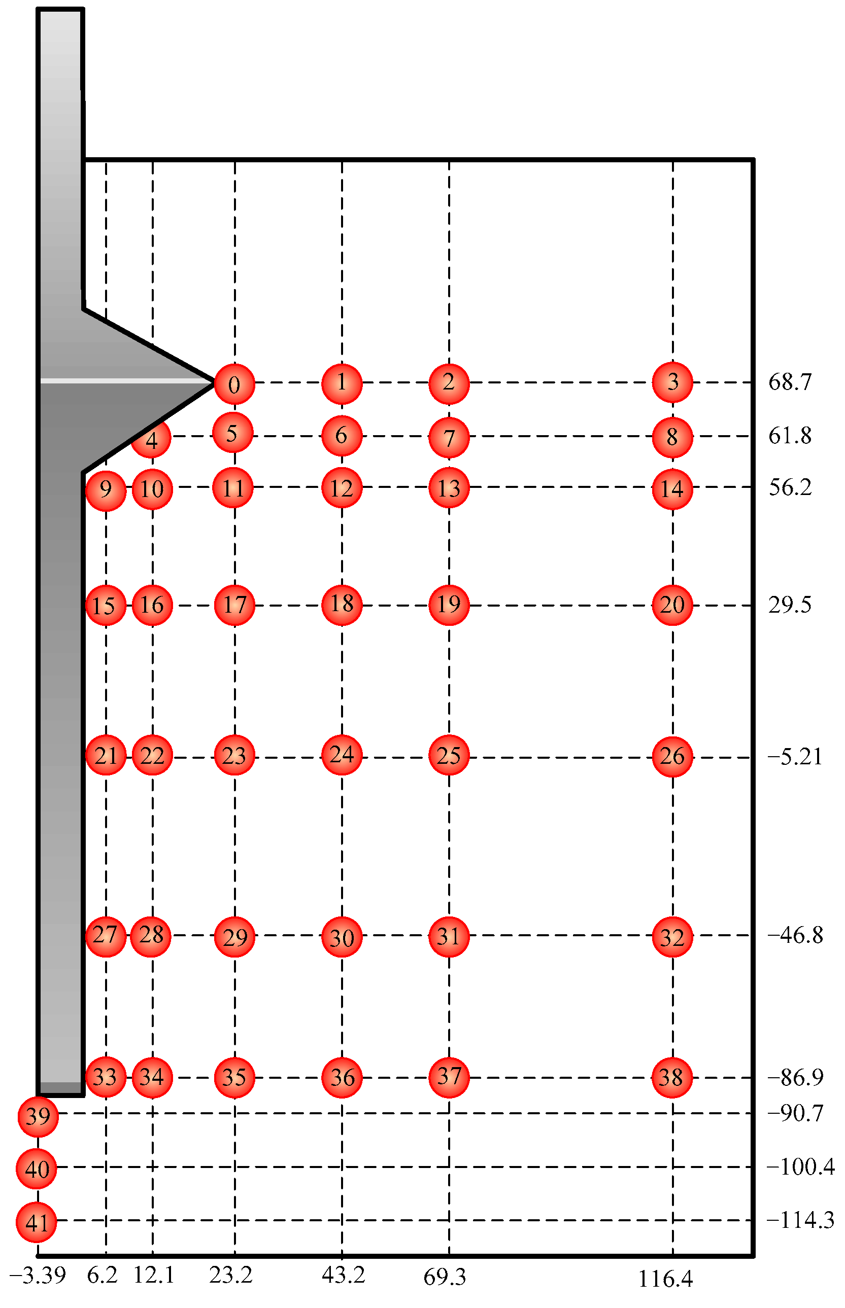
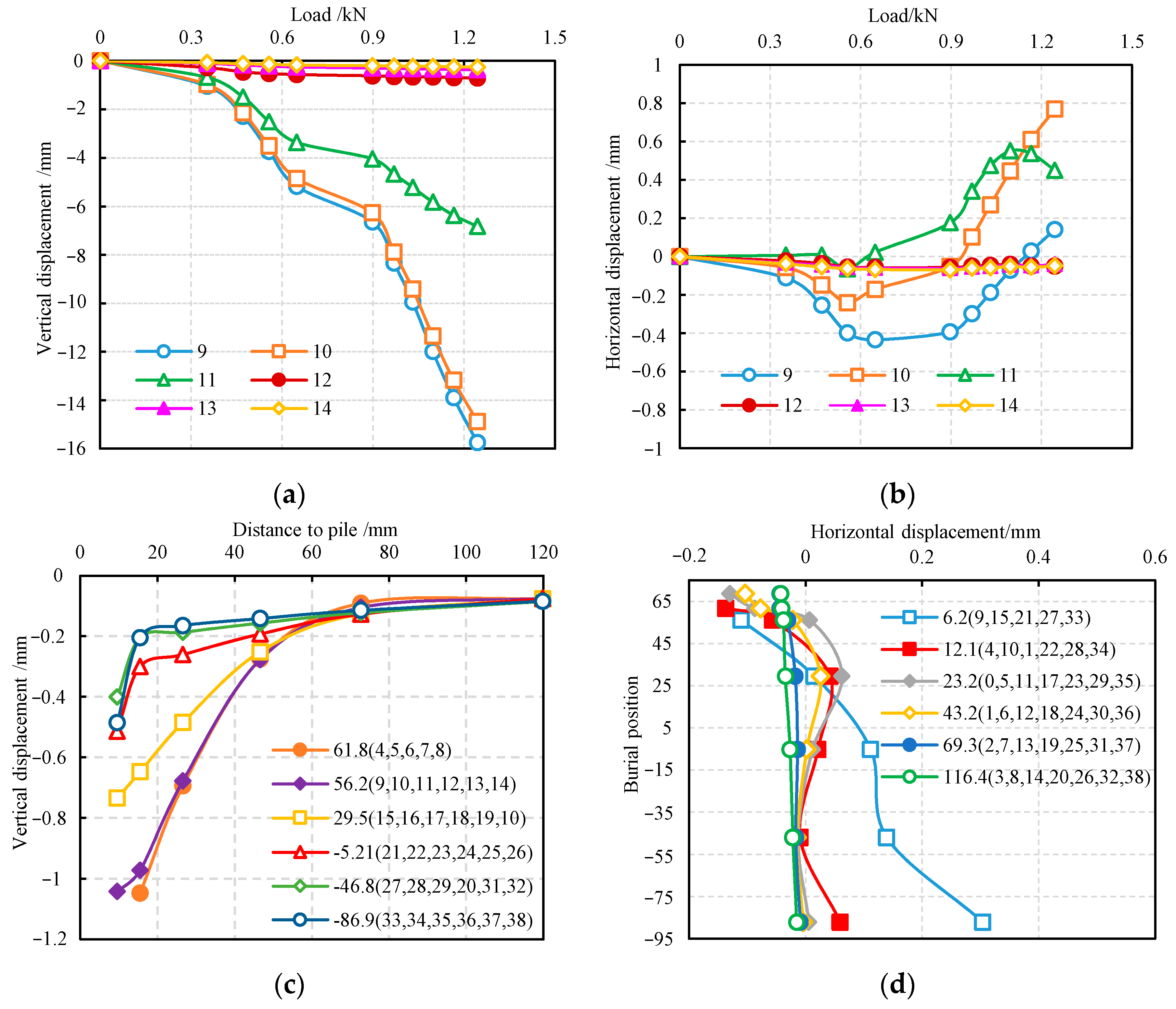
4.4.1. Displacement of the Soil at Different Positions from the Pile

Figure 13 shows the vertical and horizontal displacements of various points at different positions from the pile at the same burial depth. The test soil used in Figure 13a–d are undisturbed soil, and in Figure 13e,f are sand. Figure 13a,e demonstrate that the vertical displacement of the points closer to the pile is consistent with the overall trend of pile displacement, and the soil under the expanded body has a similar vertical displacement (Points 9 and 10). Under the same load, the largest displacements are seen at points closer to the pile body, while the displacement gradually decreases as the points move further away from the pile body. When the distance from the pile body is approximately 1.2 times that of the diameter of the expanded body, the pile body settlement has almost no effect on the soil (Figure 13c). Figure 13b,f illustrate that, under the load, the soil under the expanded body first produces a horizontal displacement toward the pile, and then, as the load increases, it produces a horizontal displacement away from the pile. This phenomenon is more pronounced closer to the pile body. During the downward movement of the pile body under force, the expanded body compresses the soil downward, causing the soil below the body to move horizontally and become denser. As the pile body continuously sinks, the expanded body produces a horizontal extrusion force, which leads to the horizontal movement of the soil away from the pile body. For the soil far away from the expanded body, there is no such phenomenon (Figure 13d).

4.4.2. Soil Displacement at Different Burial Depths

Figure 14 shows the vertical and horizontal soil displacement around the pile at different burial depths under various loads. The test soil used in Figure 14a,b are undisturbed soil, and in Figure 14c,d are sand. Figure 14a,c shows that soil closer to the expanded body has greater vertical displacement, and the displacement curve is consistent with that of the pile. As the burial depth increases, the distance from the expanded body gradually increases, and the vertical soil displacement gradually decreases. The undisturbed soil displacement at Point 4 at the bottom of the expanded body cannot be read at the later stages of loading. This is because the soil at Point 4 is continuously compressed as the load is applied, making speckles on the body surface appear to be squeezed and deformed. Consequently, there is no displacement data for them. Figure 14b,d shows the horizontal soil displacement at different burial depths under various loads. The figures show that the soil under the expanded body (at Points 4 and 10) first moves horizontally toward the pile body and then creates a horizontal displacement away from the pile body. This is because, in the initial stage of loading, the expanded body is squeezed downward under the load, and the soil at Points 4 and 10 under the expanded body moves toward the pile body and soil compaction occurs. As the load continues to increase, the entire pile body sinks. The soil near the pile body under the expanded body is continuously compacted. At the same time the expanded body moves downwards, which causes outward compression and makes the soil at Points 4 and 10 produce horizontal displacement away from the pile body. In instances of deep burial depths, the soil distant from the expanded body undergoes horizontal displacement, moving away from the pile under the load. As the burial depth increases, the horizontal displacement gradually decreases.

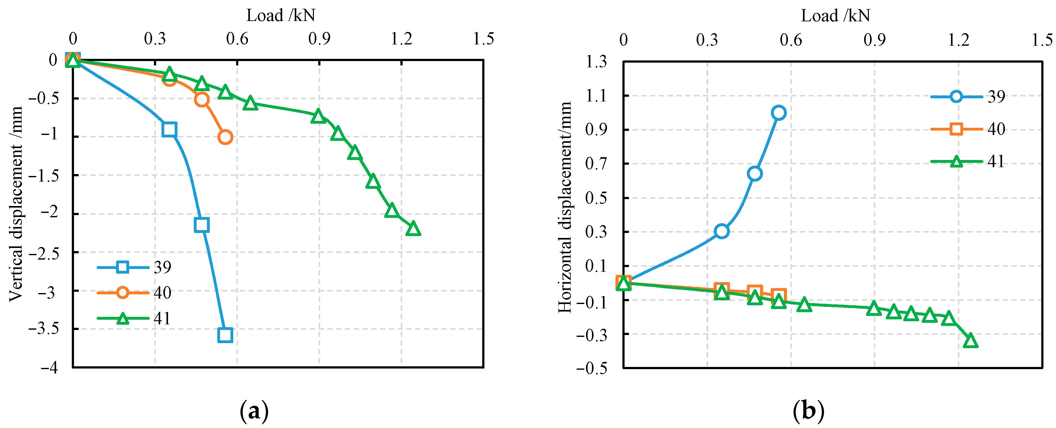
4.4.3. Soil Displacement at Different Burial Depths under the Pile Bottom

Figure 15 shows the relationship between displacement and the load at different burial depths under the bottom of the pile. The test soil used in Figure 15a,b are undisturbed soils, and in Figure 15c,d are sand. It can be seen from Figure 15a,c that the displacement is greater closer to the pile bottom. Figure 15b,d shows the horizontal displacement of the soil at different burial depths under the pile bottom. As the burial depth of the pile bottom increases, the horizontal displacement gradually decreases. In the undisturbed soil, Point 39 is close to the pile bottom, which creates horizontal displacement away from the pile body under the compression of the pile, while Points 40 and 41 are far away from the pile bottom, resulting in a horizontal displacement opposite to that of Point 39.

5. Numerical Simulation

ANASYS was used to simulate the settlement of the pile body and the displacement field of the undisturbed soil around the pile under the loads. The size of the model pile and the range of the soil around the pile were consistent with those in the model test. The parameters of pile and soil in the numerical simulation are shown in Table 3.
Figure 16 shows the relationship between load and settlement of pile top in a numerical simulation and model test. The values in the two curves are very similar. The development trends of the two curves are also relatively consistent. In order to compare the displacement field of the soil around the pile, the vertical displacement cloud picture when the load was 0.557 kN was used for comparative analysis, as shown in Figure 17. From the vertical displacement cloud picture, it can been seen that the displacement field distribution of soil around the pile obtained by numerical simulation and model test is relatively close.
Figure 18 is the vertical displacement of different data points, where the data point positions are as shown in Figure 12. It can be seen that the difference between the vertical displacement of each point in the numerical simulation and the model test is small. The errors of vertical displacement obtained by numerical simulation and experimental tests are mostly within 10%.

6. Conclusions

As described in this paper, we carried out an experimental study on the displacement characteristics of the soil around the drill-expanded concrete pile. The VIC-3D non-contact full-field strain measurement system was used to record and dynamically observe the soil displacement characteristics around the pile under the load in real-time. The soil surface displacement field around the pile was obtained through digital image correlation technology, and then the displacement characteristics of the soil around the pile were analyzed. The following conclusions were drawn:
(1)
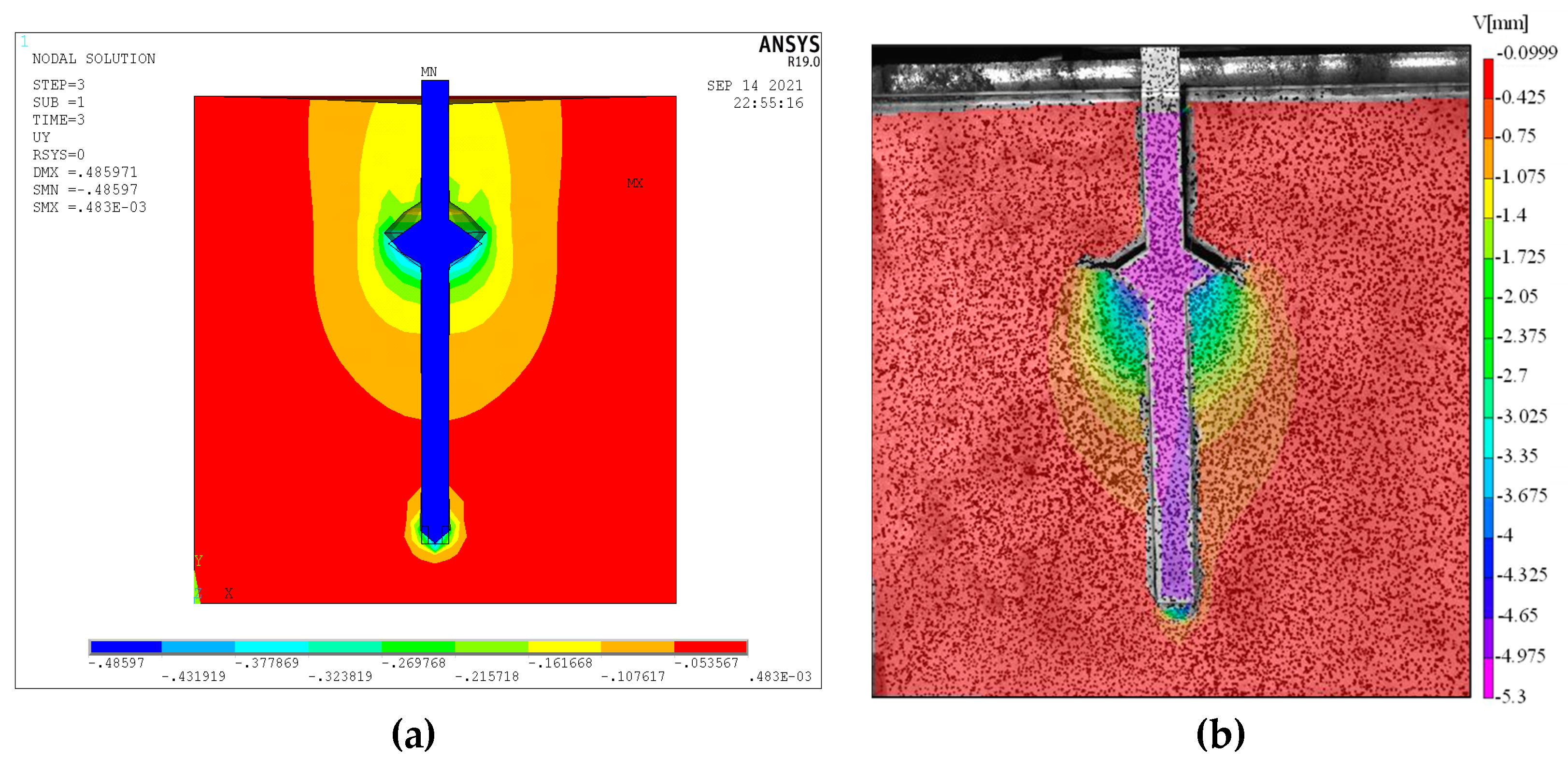
There is a clear compression zone both in the undisturbed soil and sand under the expanded body, and the compression zone has a much higher soil displacement magnitude and density than other areas. In the undisturbed soil, there is an obvious separation area between the expanded body and the soil, which is not obvious in the sand, but there is a collapse area around the pile on the top of the sand.
(2)
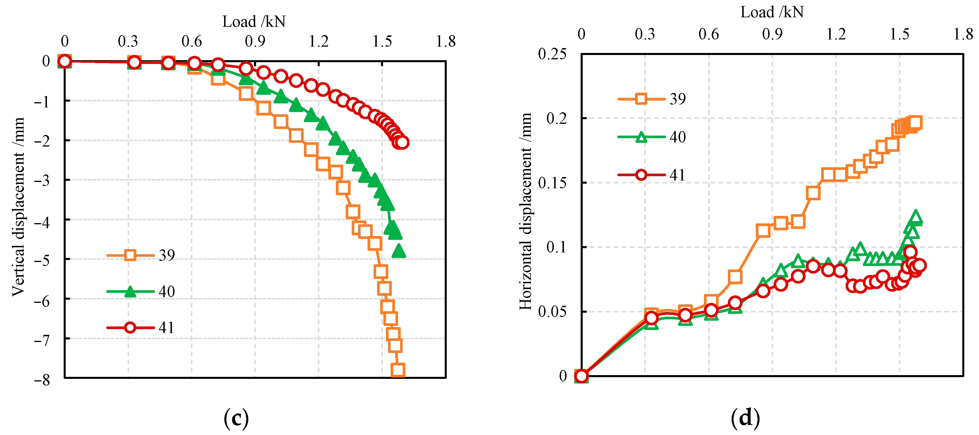
In the undisturbed soil and sand tests, the displacement trend of the soil around the pile is basically the same. The closer the soil is to the expanded body, the greater the vertical displacement, and the variation of vertical displacement with the load is essentially the same as that of the pile. The horizontal soil displacement close to the expanded body first moves towards the pile body and then moves away from the pile body; the horizontal soil displacement far away from the expanded body moves away from the pile. The closer soil is to the pile bottom, the greater the vertical displacement under load. As the depth increases, the displacement gradually decreases.
(3)
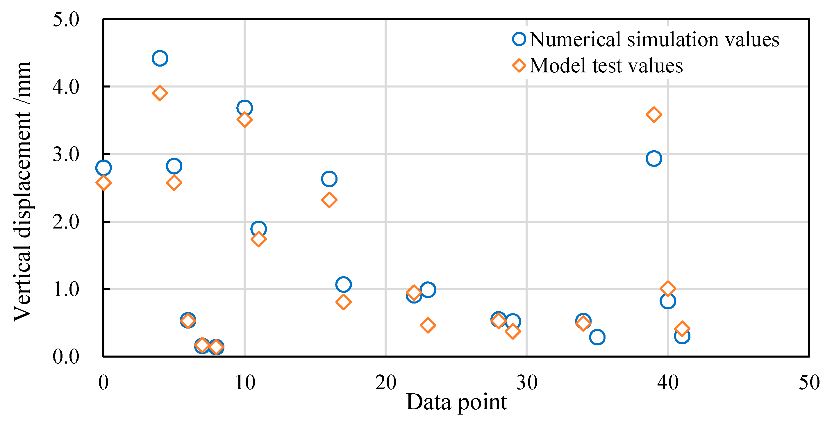
Through numerical simulation, it can be found that the displacement of the soil around the pile is basically consistent with those of the model test, which shows that the model test results are reliable.
(4)
By using a half-face pile model test and digital image correlation technology, it is possible to measure the dynamic deformation process of the soil around the pile under load with greater accuracy, to quickly and effectively obtain the soil displacement field around the pile and to more intuitively display the dynamic changes of soil displacement around the pile with the load.
(5)
For clay, although the surface of the soil around the pile will not significantly collapse under the load, there is a clear separation zone between the soil and the top surface of the expanded body, and the lateral friction resistance of the soil in the separation zone will be reduced. Thereby, the bearing capacity will be affected; but for sand, the soil above the expanded body will move down with the pile under the load, forming a collapse on the surface. Those should be considered in actual engineering construction.

Author Contributions

Conceptualization, L.X. and Y.Q.; methodology, L.X. and L.N.; investigation, L.X. and H.D.; formal analysis, H.D. and D.S.; resources, L.X.; validation, L.X. and L.N.; writing—original draft preparation, L.X.; writing—review and editing, L.X. and Y.Q. All authors have read and agreed to the published version of the manuscript.

Funding

This research was funded by the National Natural Science Foundation of China (No. 52008185 and No. 52078239).

Institutional Review Board Statement

Not applicable.

Informed Consent Statement

Not applicable.

Data Availability Statement

The data are contained within the article.

Conflicts of Interest

The authors declare no conflict of interest.

References

  1. Tamura, S.; Ohno, Y.; Shibata, K.; Funahara, H.; Nagao, T.; Kawaamata, Y. E-Defense shaking test and pushover analyses for lateral pile behavior in a group considering soil deformation in vicinity of piles. Soil Dyn. Earthq. Eng. 2021, 142, 106529. [Google Scholar] [CrossRef]
  2. Yang, J.C.; Ding, X.M.; Wang, C.L.; Wu, D.F.; Xiao, Z.W. Numerical simulation of vibration response of soil around a single pile under traffic load and sloping bedrock condition. J. Cen. S. Univ. 2020, 51, 1575–1583. [Google Scholar] [CrossRef]
  3. Conte, E.; Pugliese, L.; Troncone, A.; Vena, M. A simple approach for evaluating the bearing capacity of piles subjected to inclined loads. Int. J. Geomech. 2021, 21, 04021224. [Google Scholar] [CrossRef]
  4. Achmus, M.; Thieken, K. On the behavior of piles in non-cohesive soil under combined horizontal and vertical loading. Acta Geotech. 2010, 5, 199–210. [Google Scholar] [CrossRef]
  5. Li, L.; Li, J.P.; Sun, D.A.; Yue, Z.W. Pile jacking-in effects considering stress anisotropy of natural clay. Chin. J. Rock. Mech. Eng. 2016, 35, 1055–1064. [Google Scholar] [CrossRef]
  6. Li, L.; Gong, W.B.; Li, J.P. Effects of clay creep on long-term load-carrying behaviors of bored piles: Aiming at reusing existing bored piles. Int. J. Geomech. 2020, 20, 04020132. [Google Scholar] [CrossRef]
  7. Korff, M.; Mair, R.J.; Van, T.F. Pile-soil interaction and settlement effects induced by deep excavations. J. Geotech. Geoenviron. 2016, 142, 04016034. [Google Scholar] [CrossRef] [Green Version]
  8. Yuan, B.X.; Xiong, L.; Zhai, L.H.; Zhou, Y.F.; Chen, G.F.; Gong, X.; Zhang, W. Transparent synthetic soil and its application in modeling of soil-structure interaction using optical system. Front. Earth Sci. 2019, 7, 276. [Google Scholar] [CrossRef]
  9. Ads, A.; Iskander, M.; Bless, S. Soil-projectile interaction during penetration of a transparent clay simulant. Acta Geotech. 2020, 15, 815–826. [Google Scholar] [CrossRef]
  10. Xu, Z.J.; Guo, Z.X. Experimental study on bearing characteristics and soil deformation of necking pile with cap using transparent soils technology. Adv. Civ. Eng. 2021, 2021, 6625556. [Google Scholar] [CrossRef]
  11. Yuan, B.X.; Sun, M.; Xiong, L.; Luo, Q.Z.; Pradhan, S.P.; Li, H.Z. Investigation of 3D deformation of transparent soil around a laterally loaded pile based on a hydraulic gradient model test. J. Build. Eng. 2020, 28, 101024. [Google Scholar] [CrossRef]
  12. Qian, Y.M.; Liu, J.L.; Wang, R.Z.; Jin, Y.J. Position on soil failure state of expanded pile under horizontal force in oceanographic engineering. J. Coastal Res. 2020, 108, 274–282. [Google Scholar] [CrossRef]
  13. Qian, Y.M.; Zhou, T.T.; Tian, W. Anti-Overturning Bearing capacity of rigid and flexible concrete expanded piles subjected to horizontal load. Adv. Civ. Eng. 2020, 2020, 4901069. [Google Scholar] [CrossRef]
  14. Fang, T.; Huang, M.; Tang, K. Cross-section piles in transparent soil under different dimensional conditions subjected to vertical load: An experimental study. Arab. J. Geosci. 2020, 13, 1133. [Google Scholar] [CrossRef]
  15. Zhang, Q.; Chen, Z.; Li, J.; Liu, S. Pressure-cast-in-situ pile with spray-expanded frustum: Construction equipment and process. J. Constr. Eng. Manag. 2021, 147, 06021002. [Google Scholar] [CrossRef]
  16. Ju, Y.; Chen, Y. Experimental study for the bearing capacity calculation of concrete expanded plates in squeezed branch piles. Mater. Test. 2018, 60, 1118–1124. [Google Scholar] [CrossRef]
  17. Omidvar, M.; Chen, Z.; Iskander, M. Image based Lagrangian analysis of granular kinematics. ASCE J. Comput. Civ. Eng. 2015, 29, 04014101. [Google Scholar] [CrossRef]
  18. Qi, C.G.; Iskander, M.; Omidvar, M. Soil deformations during casing jacking and extraction of expanded-shoe piles, using model tests. Geotech. Geol. Eng. 2017, 35, 809–826. [Google Scholar] [CrossRef]
  19. Sato, T.; Onda, K.; Otani, J. Development of a new loading test apparatus for microfocus X-ray CT and its application to the investigation of soil behavior surrounding driven open-section piles. Soil Found. 2018, 58, 776–785. [Google Scholar] [CrossRef]
  20. Arshad, M.I.; Tehrani, F.S.; Prezzi, M.; Salgado, R. Experimental study of cone penetration in silica sand using digital image correlation. Géotechnique 2014, 64, 551–569. [Google Scholar] [CrossRef]
  21. Tovar-Valencia, R.D.; Galvis-Castro, A.; Salgado, R.; Prezzi, M. Effect of surface roughness on the shaft resistance of displacement model piles in sand. J. Geotech. Geoenviron. 2018, 144, 04017120. [Google Scholar] [CrossRef]
  22. Cao, Z.H.; Kong, G.Q.; Liu, H.L.; Zhou, H. Model test on deformation characteristic of pile driving in sand using PIV technique. Eng. Mech. 2014, 31, 168–174. [Google Scholar] [CrossRef]
  23. Lu, Y.; Wang, X.Y.; Sun, H.Q.; Li, X.J. Analyses on soil displacement field caused by press-in process of pile model tests. J. Tongji Univ. 2018, 46, 1366–1373. [Google Scholar] [CrossRef]
  24. Galvis-Castro, A.C.; Tovar-Valencia, R.D.; Salgado, R.; Prezzi, M. Compressive and tensile shaft resistance of nondisplacement piles in sand. J. Geotech. Geoenviron. 2019, 14, 04019041. [Google Scholar] [CrossRef]
  25. Chen, Y.D.; Deng, A.; Wang, A.T.; Sun, H.S. Performance of screw–shaft pile in sand: Model test and DEM simulation. Comput. Geotech. 2018, 104, 118–130. [Google Scholar] [CrossRef]
  26. Lin, L.; Tang, C.S.; Cheng, Q.; Zeng, H.; Shi, B. Desiccation cracking bebavior of soils based on digital image correlation technique. Chin. J. Geotech. Eng. 2019, 41, 1311–1318. [Google Scholar] [CrossRef]
Figure 1. The process of creating a drill-expanded concrete pile and a photo of a real pile: (a) drilling the hole; (b) expanding the hole; (c) expanding completed; (d) pouring concrete; (e) photo of a real drill-expanded concrete pile.
Applsci 11 09097 g001
Figure 2. Soil sample from the undisturbed soil in the half-face pile test.
Applsci 11 09097 g002
Figure 3. Particle size distribution curve.
Applsci 11 09097 g003
Figure 4. Model pile and the pile anchoring process: (a) schematic diagram of model pile; (b) photos of the embedding process of the pile in the undisturbed soil; (c) photos of embedding process of the pile in the sand.
Applsci 11 09097 g004
Figure 5. Collection of surface painting photos.
Applsci 11 09097 g005
Figure 6. Loading platform.
Applsci 11 09097 g006
Figure 7. Loading and VIC-3D test system.
Applsci 11 09097 g007
Figure 8. Load and settlement of pile top curve.
Applsci 11 09097 g008
Figure 9. Surface images of the collection area under different loads: (a) undisturbed soil; (b) sand.
Applsci 11 09097 g009
Figure 10. Schematic diagram of undisturbed soil cracking under force at the tip of the expanded body (a is the length of the expanded body; Δa is the newly expanded crack length; G is crack propagation force).
Applsci 11 09097 g010
Figure 11. Soil deformation field around the expanded body under the load (V represents vertical displacement): (a) undisturbed soil; (b) sand.
Applsci 11 09097 g011
Figure 12. Data point distribution map.
Applsci 11 09097 g012
Figure 13. Relationships between displacement and load at different positions of the same burial depth around the pile: (a) relationship between vertical displacement and loads in the undisturbed soil; (b) relationship between horizontal displacement and loads in the undisturbed soil; (c) relationship between vertical displacement and positions in the undisturbed soil (load: 0.352 kN); (d) relationship between horizontal displacement and burial position in the undisturbed soil (load: 0.352 kN); (e) relationship between vertical displacement and loads in the sand; (f) relationship between horizontal displacement and loads in the sand.
Applsci 11 09097 g013aApplsci 11 09097 g013b
Figure 14. Relationship between displacement and load at different burial depths around the pile: (a) vertical displacement in the undisturbed soil; (b) horizontal displacement in the undisturbed soil; (c) vertical displacement in the sand; (d) horizontal displacement in the sand.
Applsci 11 09097 g014
Figure 15. The relationship between displacement and the load at different burial depths under the pile bottom: (a) vertical displacement in the undisturbed soil; (b) horizontal displacement in the undisturbed soil; (c) vertical displacement in the sand; (d) horizontal displacement in the sand.
Applsci 11 09097 g015aApplsci 11 09097 g015b
Figure 16. Relationship between load and settlement of pile top in numerical simulation and model test.
Applsci 11 09097 g016
Figure 17. The vertical displacement cloud picture (0.557 kN): (a) numerical simulation; (b) model test.
Applsci 11 09097 g017
Figure 18. Vertical displacement of different data points.
Applsci 11 09097 g018
Table 1. Physical properties of the undisturbed soil.
ParametersValues
Density (g/cm3)1.61
Liquid limit water content (%)36.9
Plastic limit water content (%)20.06
Plasticity Index16.84
Natural water content (%)22
Table 2. Physical properties of white quartz sand.
ParametersValues
Particle size (mm)0.425–0.85
Minimum dry density (g/cm3)1.1
Maximum dry density (g/cm3)1.75
Silica content (%)99
Internal friction angle (°)45.17
Table 3. The parameters of pile and soil in the numerical simulation.
MaterialsPileSoil
Density (×103 kg/m3)7.851.8
Elastic Modulus (MPa)20e425
Poisson’s ratio0.20.35
Cohesion (MPa)0.04355
Internal friction angle (°)10.7
Expansion angle (°)10.7
Pile-soil friction coefficient0.3
Publisher’s Note: MDPI stays neutral with regard to jurisdictional claims in published maps and institutional affiliations.

