Selected Aspects of Designing Modular PEMFC Stacks as Power Sources for Unmanned Aerial Vehicles


Abstract
:1. Introduction
2. Experimental Parts
2.1. Description of Designed and Assembled Modular PEMFC Stacks
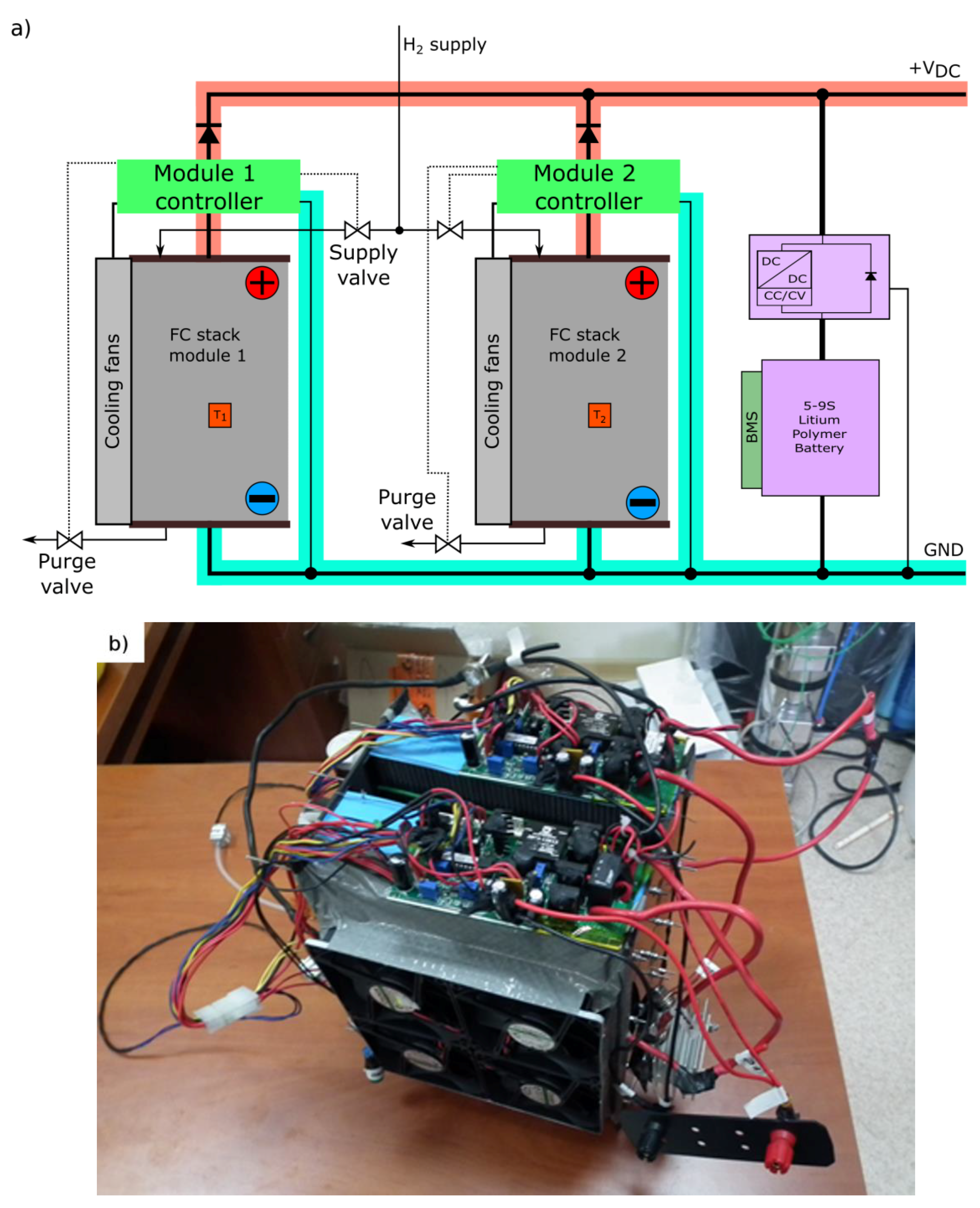
2.1.1. First Power Source: A 2000-W PEMFC Stack Constructed from Two 1-kW Modules Electrically Connected in Parallel
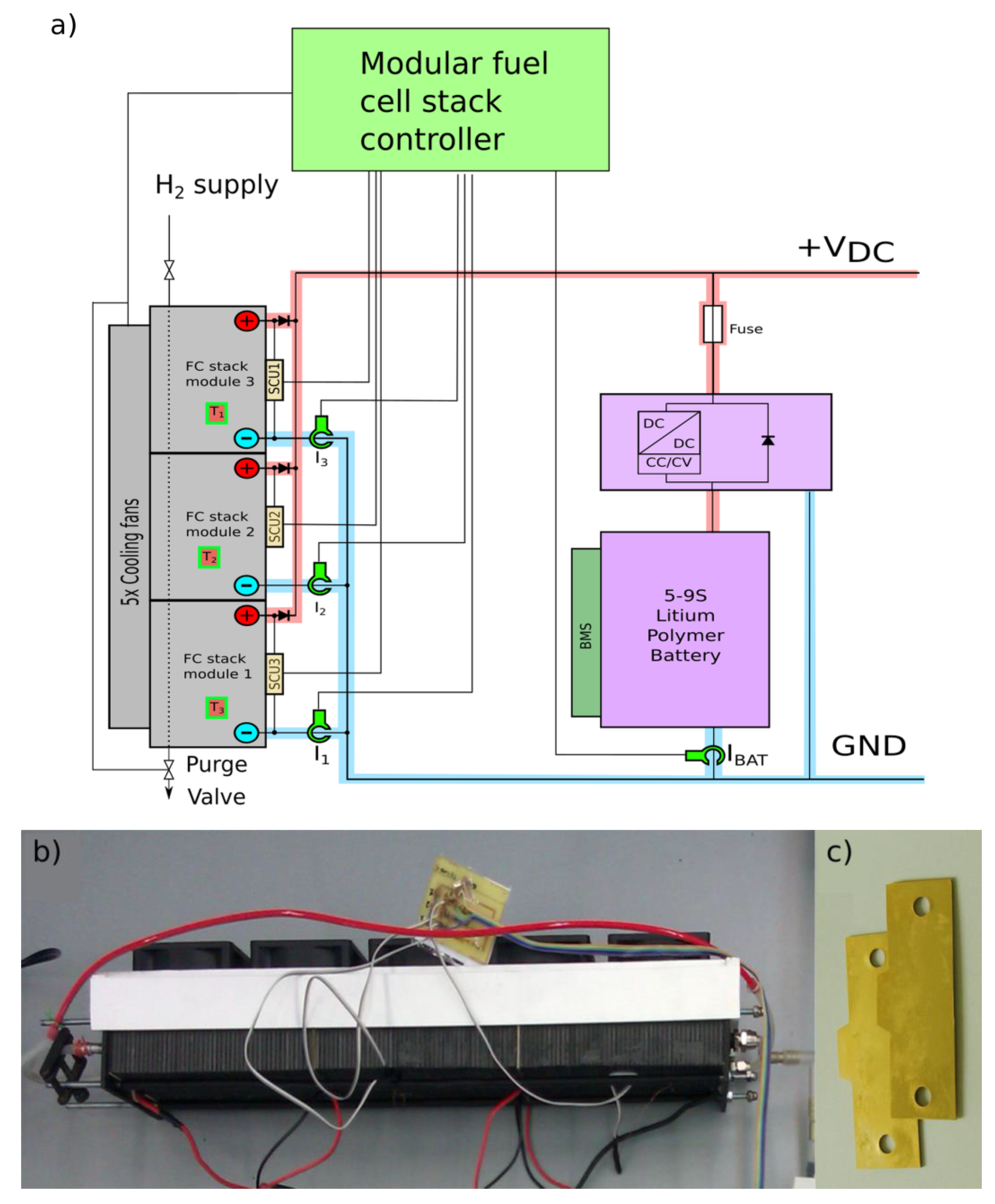
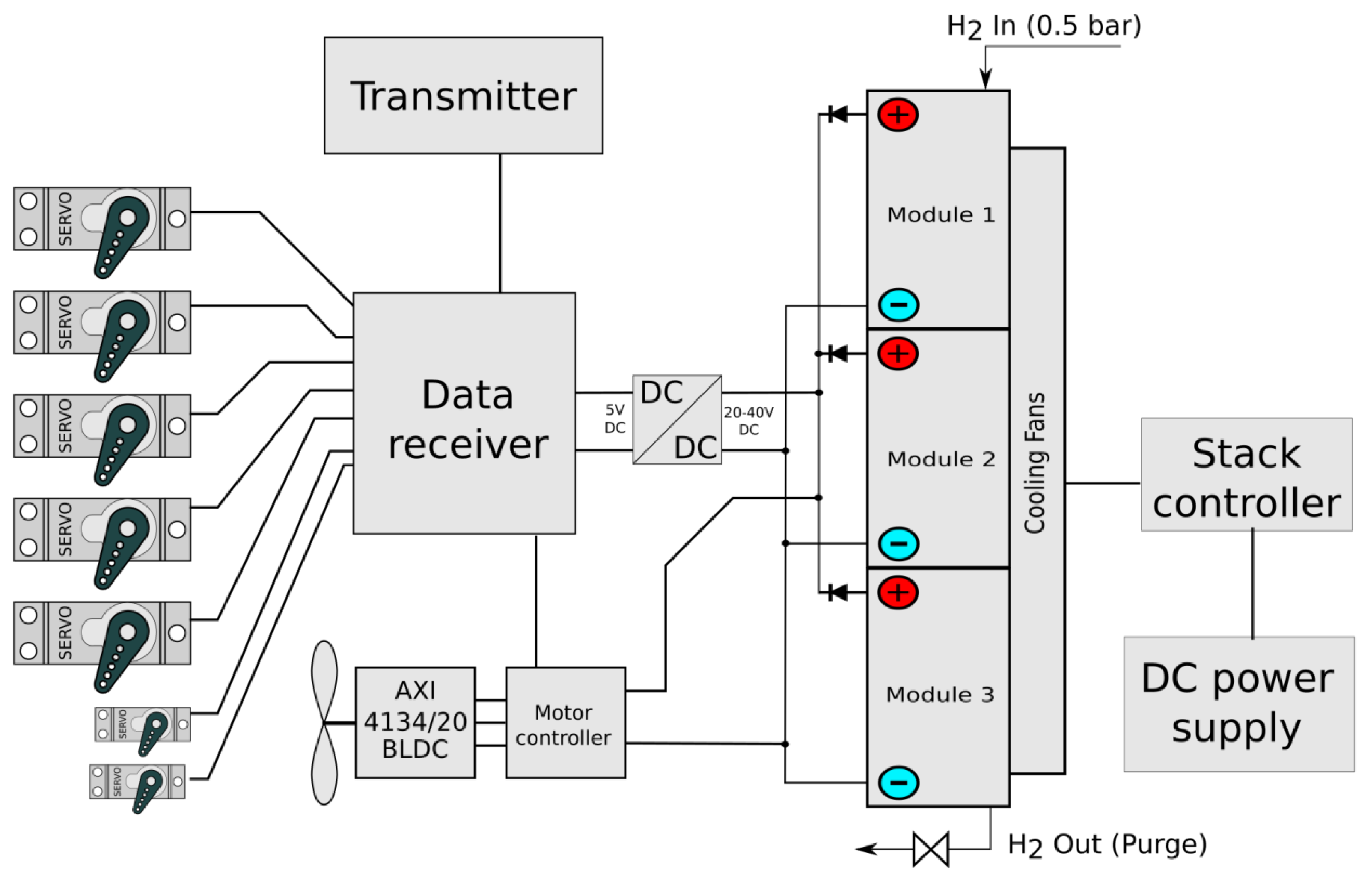
2.1.2. Second Power Source: A 500-W PEMFC Stack with Three Modules Connected in Parallel
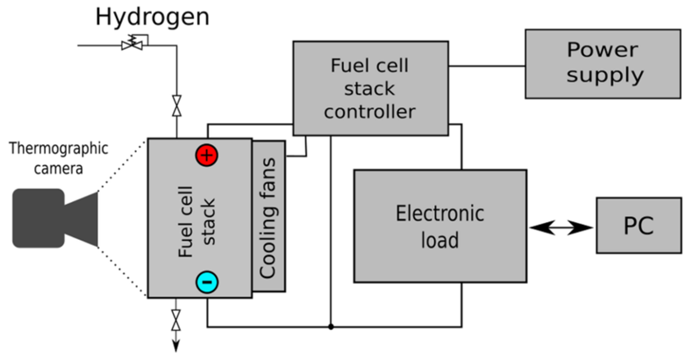
2.2. Method of Measurement and Measuring Equipment Used
3. Results
3.1. Electrical Tests of the Designed Two-Module 2-kW PEMFC Stack
3.1.1. Comparison of Electrical Performance of the Designed Two-Module PEMFC Fuel Cell Stack with Other Commercial PEMFC Fuel Cell Stacks
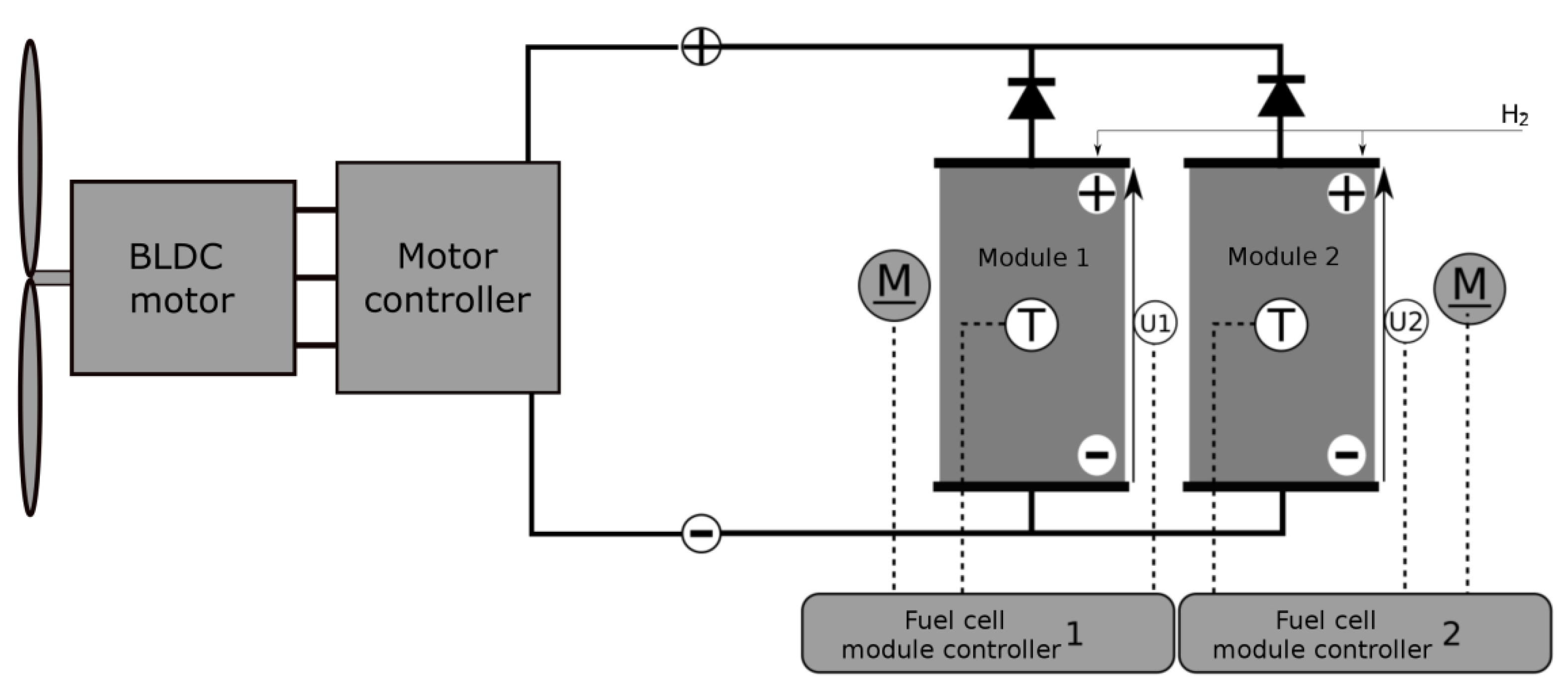
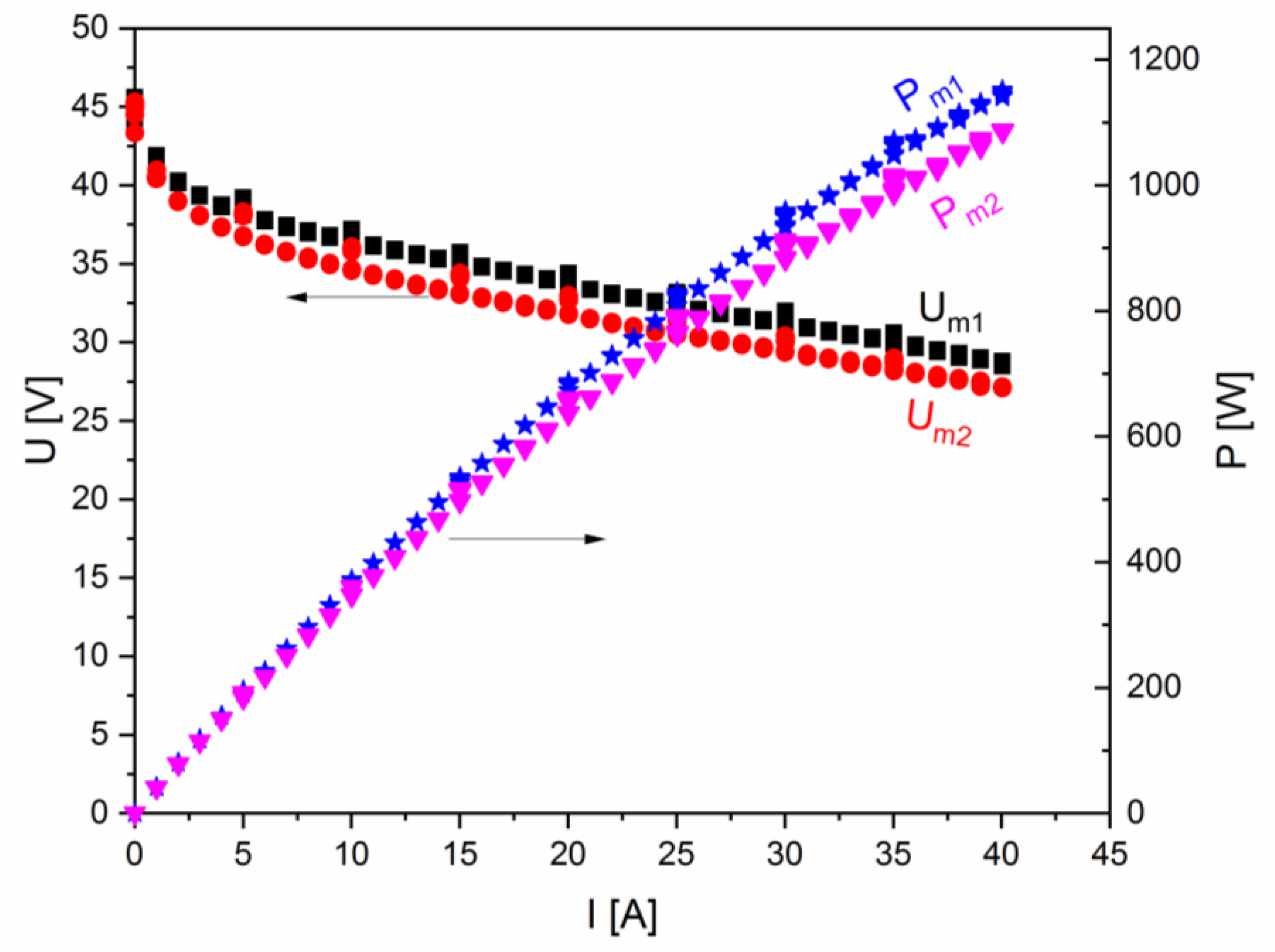
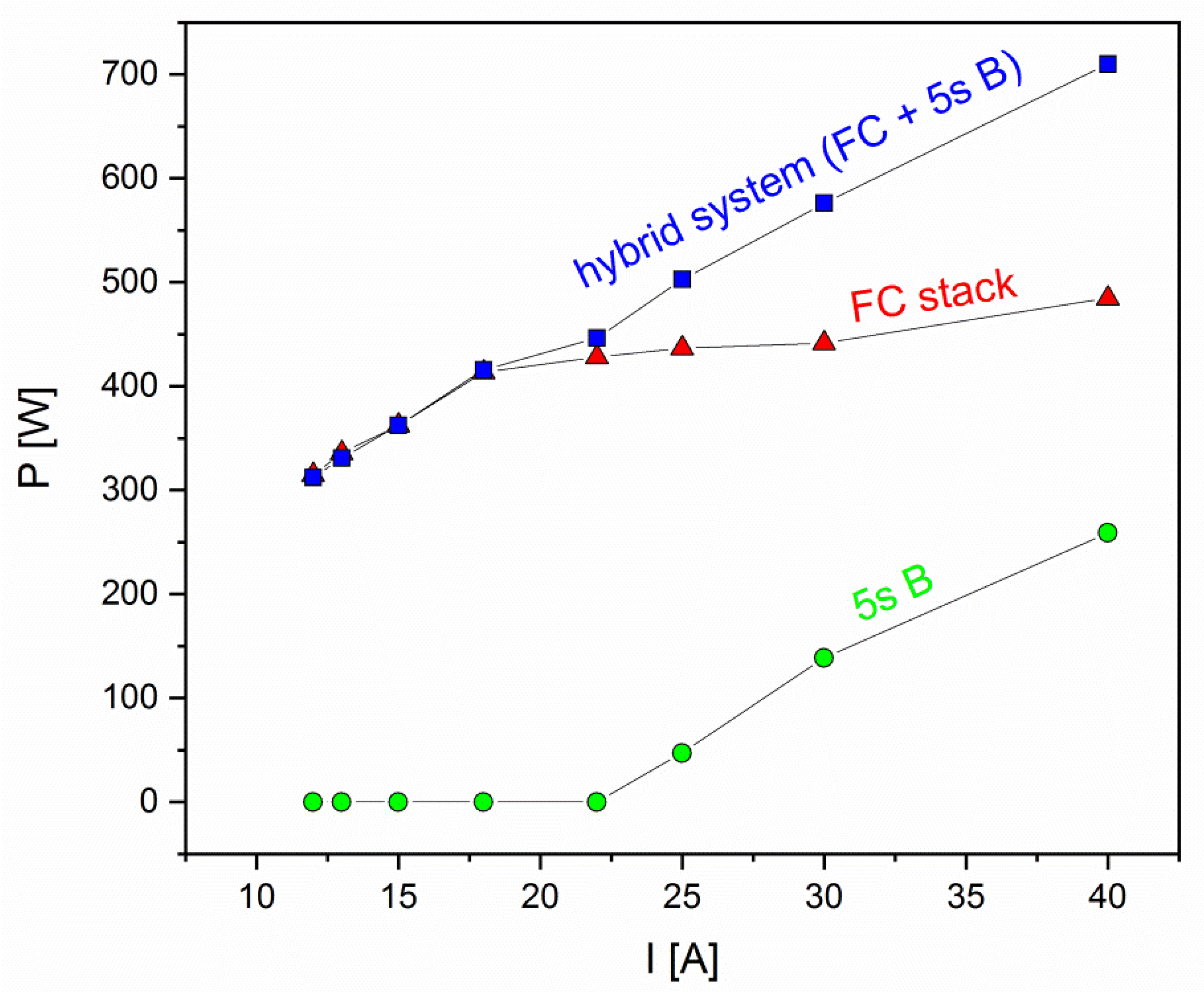
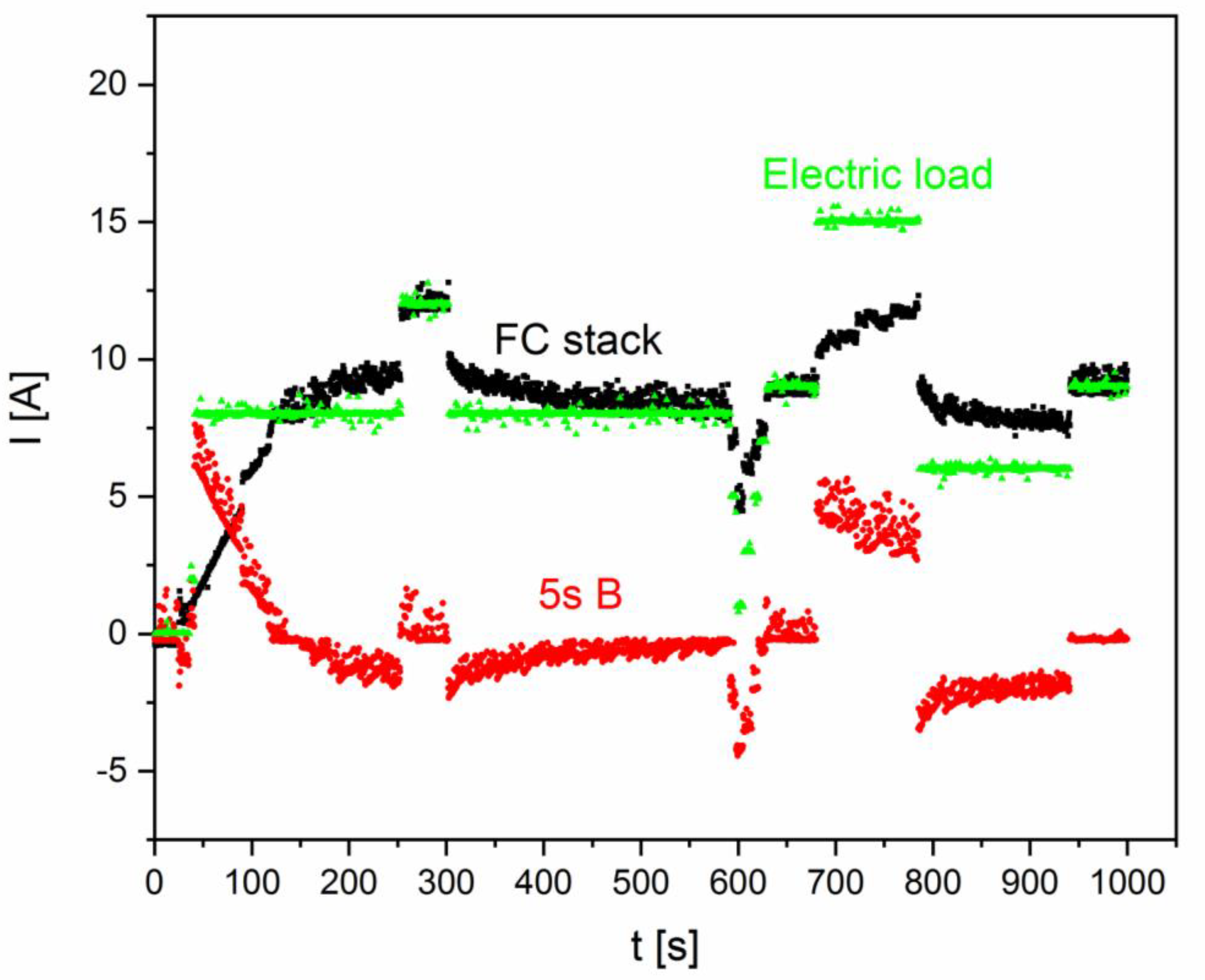
3.1.2. Test of the Electrical Performance of the Designed Two-Module PEMFC Fuel Cell Stack with a Propeller Connected to a BLDC Motor
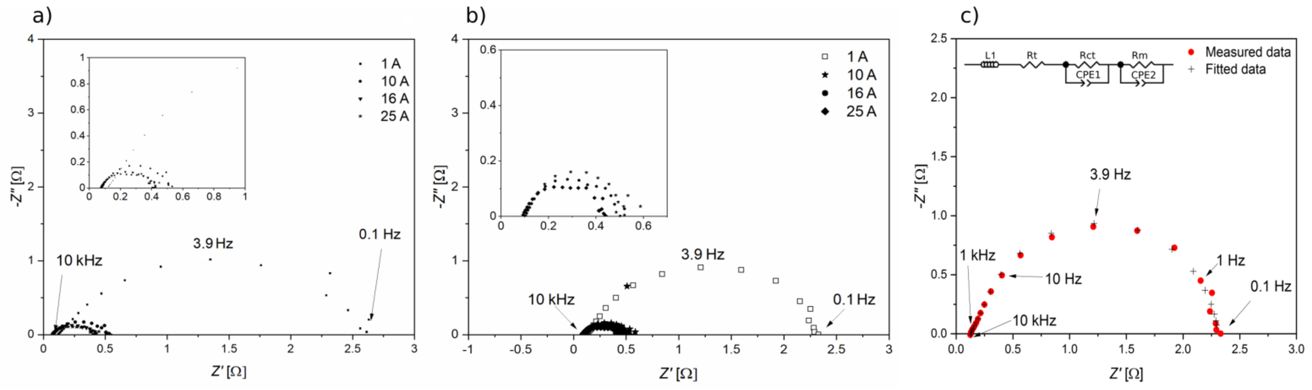
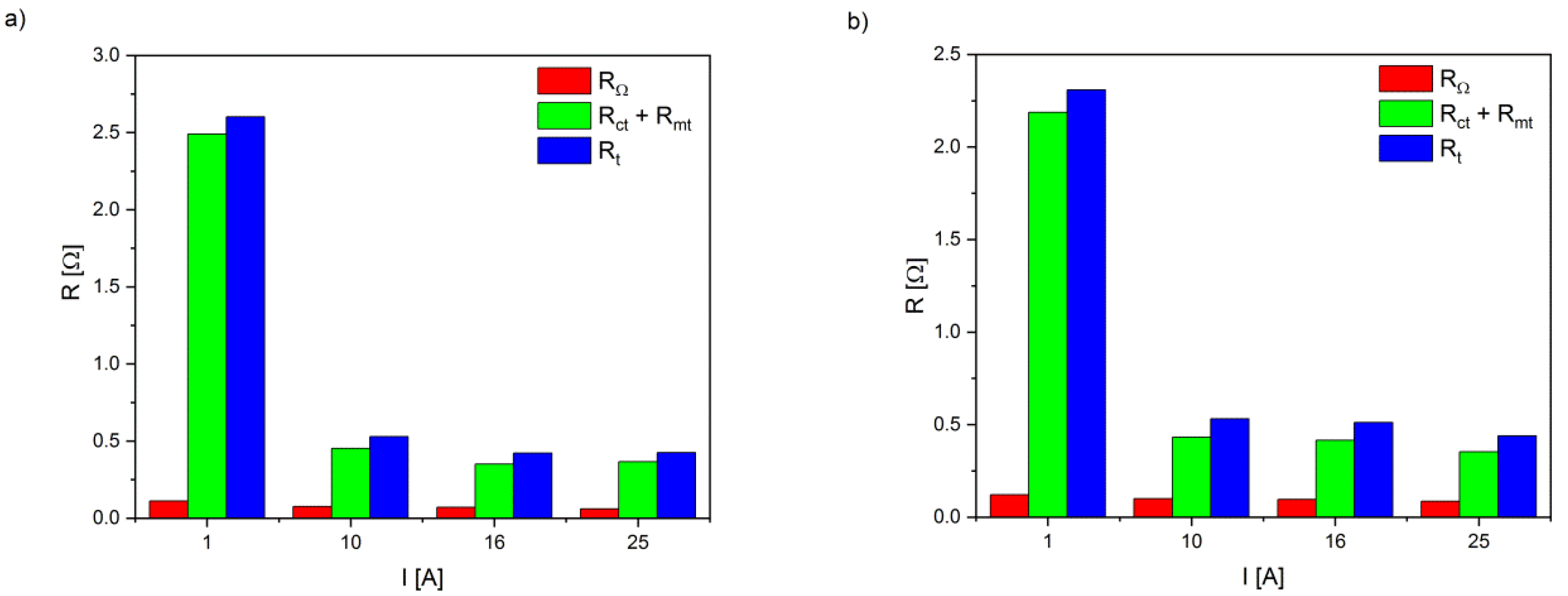
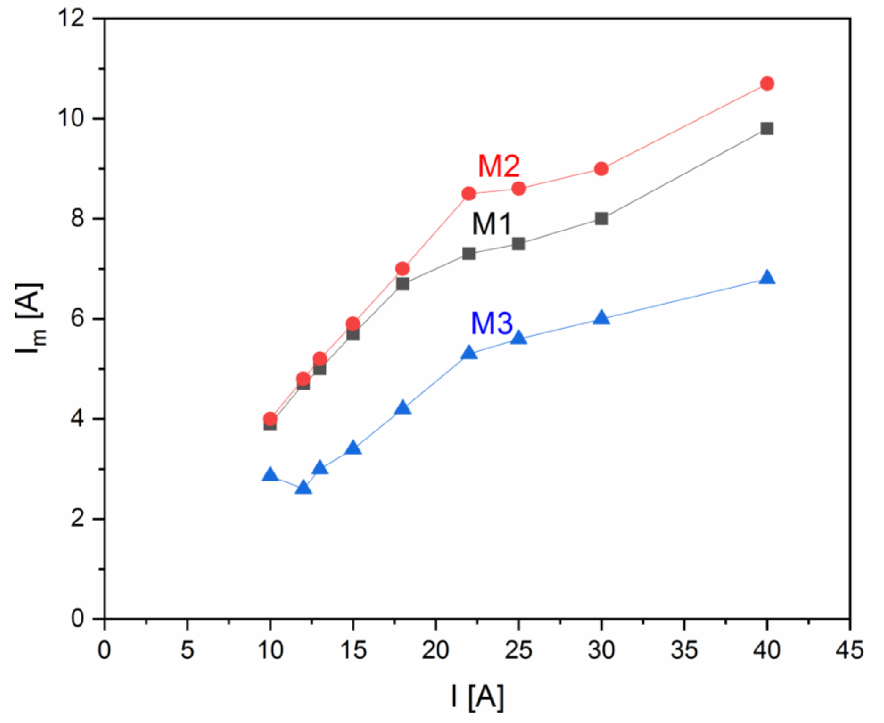
3.2. Electrical Tests of the 500-W PEMFC Stack
4. Conclusions
Author Contributions
Funding
Institutional Review Board Statement
Informed Consent Statement
Data Availability Statement
Acknowledgments
Conflicts of Interest
Nomenclature
| FC | fuel cells |
| Mi | PEMFC module; i = 1; 2; 3 |
| PEMFC | polymer membrane fuel cells |
| 5s Li-Pol | lithium polymer battery contained 5 cells connected in series |
| UAVs | unmanned aerial vehicles |
| MEA | membrane electrode assembly |
| GDL | gas diffusion layers |
| SOC | state of charge |
| MCFC | multistack fuel cell |
| DC | direct constant current |
| EIS | electrochemical impedance spectroscopy |
| EEC | equivalent electrical circuit |
| CPE | constant phase element |
| BOP | balance of fuel cell power plant |
| FH2 | hydrogen intensity flow (Ndm3/min) |
| RΩ | ohmic resistance spectroscopy |
| Rct | charge transfer resistance |
| Rm | mass transport resistance |
| Rt | total electrical resistance |
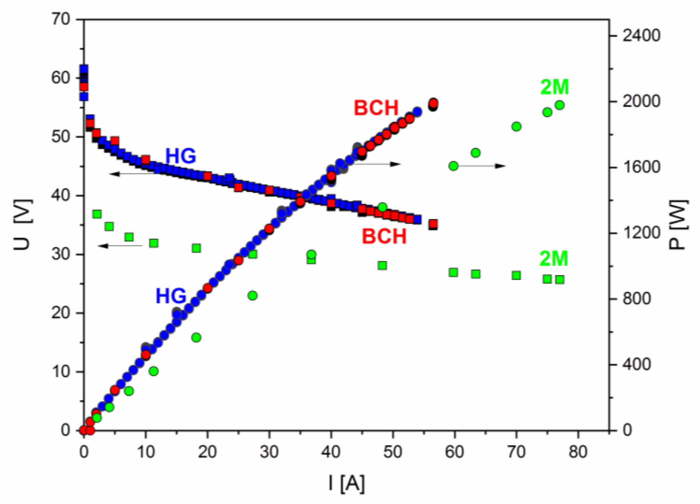
| HG | 2-kW PEMFC stack with graphite bipolar plate (product H series, Horizon Fuel Cell Technologies Pte Ltd; Singapore) |
| BCH | 2 kW BCH Energy (Jiangsu Ice-City Hydrogen Energy Technology Co., Ltd., Danyang, China) |
| 2M | 2-kW PEMFC stack consisting of two fuel cell modules, |
| BLDC | brushless direct-current motor |
| MCU | microcontroller system units |
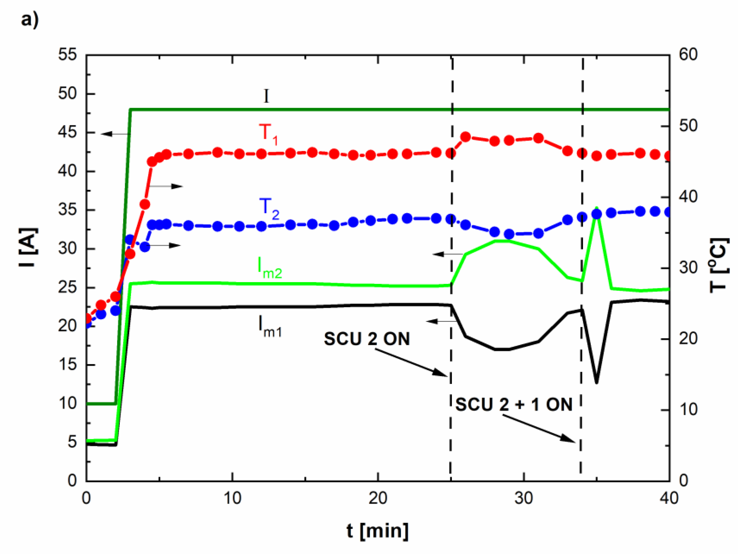
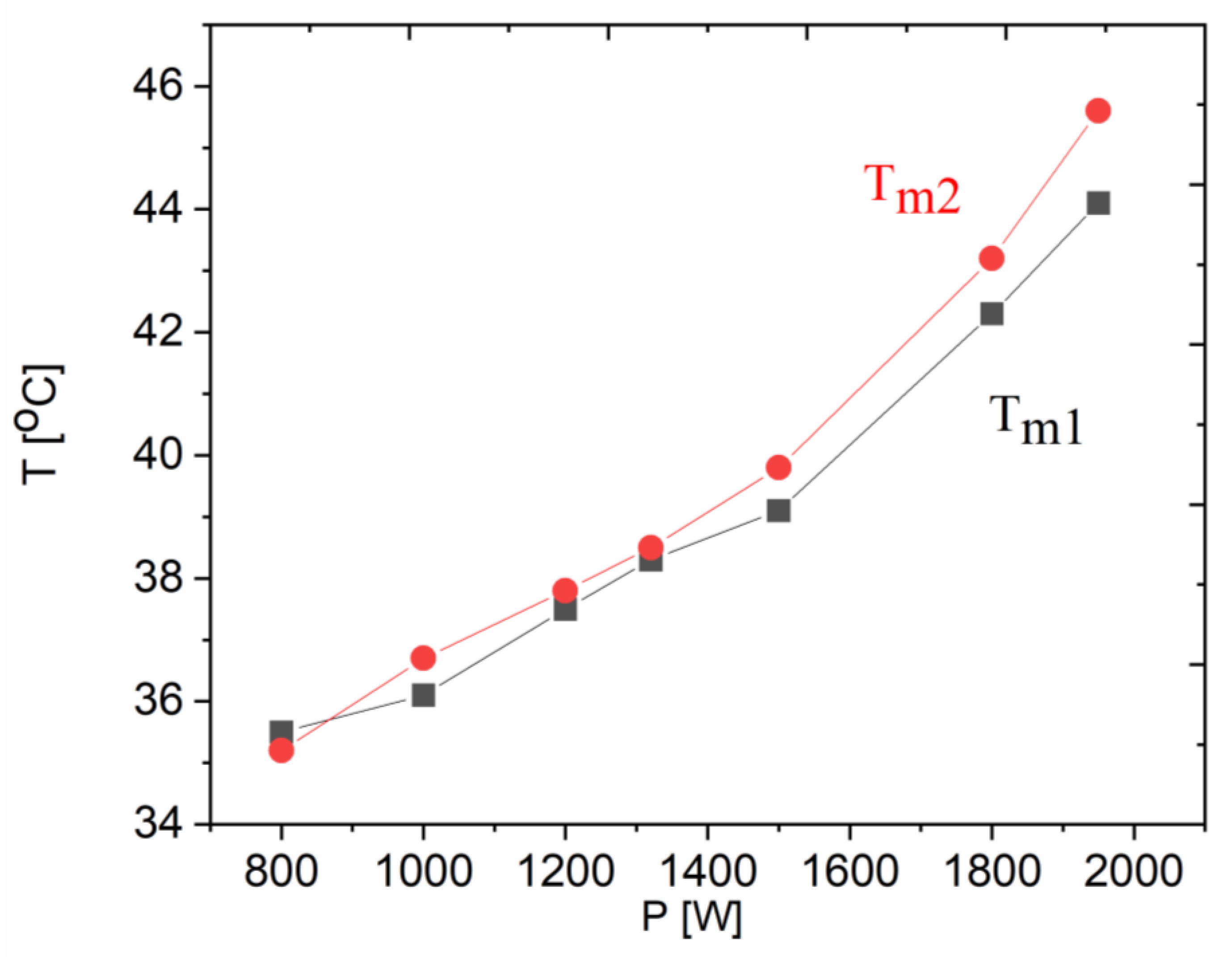
| Tm1 | temperature; PEMFC module 1 |
| Tm2 | temperature; PEMFC module 2 |
| Pfan | electrical power needed to supply the cooling system |
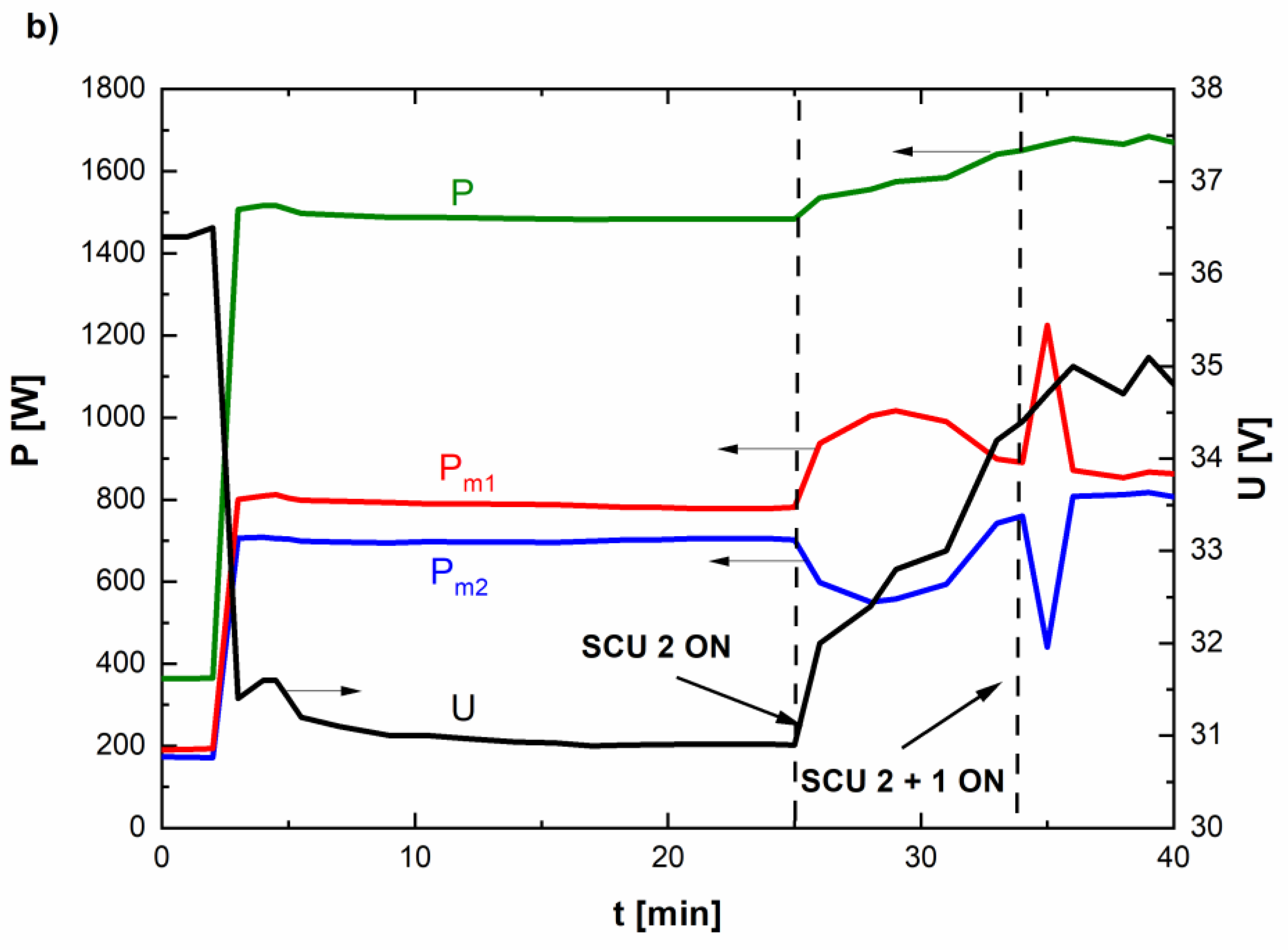
| U | voltage |
| I | current |
| Im | current of PEMFC module fuel cell stack |
| Um1 | voltage, PEMFC module 1 |
| Um2 | voltage, PEMFC module 2 |
| Pm1 | power, PEMFC module 1 |
| Pm2 | power, PEMFC module 2 |
| Q | heat |
| V | stream of air |
| ρ | the air density |
| Cpp | the specific heat of the air |
| SCU | short-circuit units |
| PC | personal computer |
| Z’ | real part of impedance plot |
| Z” | imaginary part of impedance plot |
References
- Hassanalian, M.; Abdelkefi, A. Classifications, applications, and design challenges of drones: A review. Prog. Aerosp. Sci. 2017, 91, 99–131. [Google Scholar] [CrossRef]
- Outay, F.; Mengash, H.A.; Adnan, M. Applications of unmanned aerial vehicle (UAV) in road safety, traffic and highway infrastructure management: Recent advances and challenges. Transp. Res. Part A Policy Pract. 2020, 141, 116–129. [Google Scholar] [CrossRef] [PubMed]
- Mishra, B.; Garg, D.; Narang, P.; Mishra, V. Drone-surveillance for search and rescue in natural disaster. Comput. Commun. 2020, 156, 1–10. [Google Scholar] [CrossRef]
- Alzahrani, B.; Oubbati, O.S.; Barnawi, A.; Atiquzzaman, M.; Alghazzawi, D. UAV assistance paradigm: State-of-the-art in applications and challenges. J. Netw. Comput. Appl. 2020, 166, 10270. [Google Scholar] [CrossRef]
- Aydin, B. Public acceptance of drones: Knowledge, attitudes, and practice. Technol. Soc. 2019, 59, 101180. [Google Scholar] [CrossRef]
- Nouacer, R.; Hussein, M.; Espinoza, H.; Ouhammou, Y.; Ladeira, M.; Castiñeira, R. Towards a framework of key technologies for drones. MiCrop. Microsyst. 2020, 77, 103142. [Google Scholar] [CrossRef]
- Vilbig, J.M.; Sagan, V.; Bodine, C. Archaeological surveying with airborne LiDAR and UAV photogrammetry: A comparative analysis at Cahokia Mounds. J. Archaeol. Sci. Rep. 2020, 33, 102509. [Google Scholar]
- Zhang, M.; Li, S.; Yu, F.; Tian, X. Image fusion employing adaptive spectral-spatial gradient sparse regularization in UAV remote sensing. Signal Process. 2020, 170, 107434. [Google Scholar] [CrossRef]
- Kim, S.J.; Lim, G.J.; Cho, J. Drone flight scheduling under uncertainty on battery duration and air temperature. Comput. Ind. Eng. 2018, 117, 291–302. [Google Scholar] [CrossRef]
- Sato, M.; Nirei, M.; Yamanaka, Y.; Suzuki, T.; Bu, Y.; Mizuno, T. Increasing the efficiency of a drone motor by arranging magnetic sheets to winding. Energy Rep. 2020, 6, 439–446. [Google Scholar] [CrossRef]
- UAV—Fuel Cell Solutions Ballard Power. Available online: https://www.ballard.com/markets/uav (accessed on 20 November 2020).
- Osenar, P.; Sisco, J.; Reid, C. Advanced Propulsion for Small Unmanned Aerial Vehicles—The Role of Fuel Cell-Based Energy Systems for Commercial UAVs; Protonex Technology Corporation: Southborough, MA, USA, 2017. [Google Scholar]
- Depcik, C.; Cassady, T.; Collicott, B.; Burugupally, S.P.; Li, X.; Alam, S.S.; Arandia, J.R.; Hobeck, J. Comparison of lithium ion Batteries, hydrogen fueled combustion Engines, and a hydrogen fuel cell in powering a small Unmanned Aerial Vehicle. Energy Convers. Manag. 2020, 207, 112514. [Google Scholar] [CrossRef]
- Bayrak, Z.U.; Kaya, U.; Oksuztepe, E. Investigation of PEMFC performance for cruising hybrid powered fixed-wing electric UAV in different temperatures. Int. J. Hydrog. Energy 2020, 45, 7036–7045. [Google Scholar] [CrossRef]
- Giacoppo, G.; Barbera, O.; Briguglio, N.; Cipitì, F.; Ferraro, M.; Brunaccini, G.; Erdle, E.; Antonucci, V. Thermal study of a SOFC system integration in a fuselage of a hybrid electric mini UAV. Int. J. Hydrog. Energy 2017, 42, 28022–28033. [Google Scholar] [CrossRef]
- Dudek, M.; Raźniak, A.; Lis, B.; Siwek, T.; Adamczyk, B.; Uhl, D.; Kalawa, W.; Uhl, T. Monitoring of the operating parameters a low-temperature fuel-cell stack for applications in unmanned aerial vehicles: Part I. E3S Web Conf. 2019, 108, 01029. [Google Scholar] [CrossRef]
- Dudek, M.; Raźniak, A.; Lis, B.; Siwek, T.; Adamczyk, B.; Uhl, D.; Kalawa, W.; Uhl, T. Monitoring of the operating parameters a low-temperature fuel-cell stack for applications in unmanned aerial vehicles: Part II. E3S Web Conf. 2019, 108, 01030. [Google Scholar] [CrossRef]
- Kwon, S.; Kang, S.; Kim, T. Development of NaBH4-Based Hydrogen Generator for Fuel Cell Unmanned Aerial Vehicles with Movable Fuel Cartridge. Energy Procedia 2019, 158, 1930–1935. [Google Scholar] [CrossRef]
- Gong, A.; Verstraete, D. Fuel cell propulsion in small fixed-wing unmanned aerial vehicles: Current status and research needs. Int. J. Hydrog. Energy 2017, 42, 21311–22133. [Google Scholar] [CrossRef]
- Wang, B.; Zhao, D.; Li, W.; Wang, Z.; Huang, Y.; You, Y.; Becker, S. Current technolgies and challenges of applying fuel cell hybrid propulsion systems in unmanned aerial vehicles. Prog. Aerosp. Sci. 2020, 116, 100620. [Google Scholar] [CrossRef]
- Boukoberine, M.N.; Zhou, Z.; Benbouzid, M. A critical review on unmanned aerial vehicles power supply and energy management: Solutions, strategies, and prospects. Appl. Energy 2019, 255, 113823. [Google Scholar] [CrossRef]
- Verstraete, D.; Lehmkuehler, K.; Gong, A.; Harvey, J.R.; Brian, G. Characterisation of a hybrid, fuel-cell-based propulsion system for small unmanned aircraft. J. Power Sources 2014, 250, 204–211. [Google Scholar] [CrossRef]
- Dudek, M.; Tomczyk, P.; Wygonik, P.; Korkosz, M.; Bogusz, P.; Lis, B. Hybrid Fuel Cell—Battery System as a Main Power Unit for Small Unmanned Aerial Vehicles (UAV). Int. J. Electrochem. Sci. 2013, 8, 8442–8463. [Google Scholar]
- Lei, T.; Yan, Z.; Lin, Z.; Zhang, X. State of art on energy management strategy for hybrid-powered unmanned aerial vehicle. Chin. J. Aeronaut. 2019, 32, 1488–1533. [Google Scholar] [CrossRef]
- Zhang, X.; Liu, L.; Dai, Y.; Lu, T. Experimental investigation on the on line fuzzy energy management of hybrid fuel cell/battery power system for UAVs. Int. J. Hydrog. Energy 2018, 43, 10094–10103. [Google Scholar] [CrossRef]
- Ballard turnkey fuel cell solutions to power commercial UAVs. Fuel Cells Bull. 2019, 5, 6. Available online: https://www.ballard.com/about-ballard/newsroom/news-releases/2019/04/29/ballard-launches-turnkey-fuel-cell-solutions-to-power-commercial-unmanned-aerial-vehicles (accessed on 11 January 2021).
- Horizon–Raptor UAS tie-up aims for 300 km fuel cell UAV flight. Fuel Cells Bull. 2015, 9, 3.
- Intelligent Energy launches 2.4 kW fuel cell module for UAVs. Fuel Cells Bull. 2019, 5, 6.
- Energy or fuel cell multirotor drone in 2 h flight with camera. Fuel Cells Bull. 2016, 2, 3–4. Available online: https://0-www-sciencedirect-com.brum.beds.ac.uk/science/article/abs/pii/S146428591670006X (accessed on 11 January 2021).
- Chinese UAV maker MMC flies hydrogen fuel cell drone for 4 h. Fuel Cells Bull. 2016, 6, 4–5.
- Li, M.; Bai, Y.; Zhang, C.; Song, Y.; Jiang, S.; Grouset, D.; Zhang, M. Review on the research of hydrogen storage system fast refueling in fuel cell vehicle. Int. J. Hydrog. Energy 2019, 44, 10677–10693. [Google Scholar] [CrossRef] [Green Version]
- Oh, T.K. Concepual design of small unmanned aerial vehicle with proton exchange membrane fuel cell system for long endurance mission. Energy Convers. Manag. 2018, 17, 6349–6356. [Google Scholar]
- Renau, J.; Schanzes, S.; Lozzano, A.; Barroso, J.; Barreras, F. Analysis of the performance of a passive hybrid power plant to power a lightweight unmanned aerial vehicle for a high altitude mission. J. Power Sources 2017, 356, 124–132. [Google Scholar] [CrossRef] [Green Version]
- Kang, H.; Kim, S.Y. Thermal design analysis of a 1 L cryogenic liquid hydrogen tank for an unmanned aerial vehicle. Int. J. Hydrog. Energy 2014, 39, 20009–20016. [Google Scholar] [CrossRef]
- Palma, L.; Enjeti, P.N. A modular fuel cell, modular DC–DC converter concept for high performance and enhanced reliability. IEEE Trans. Power Electron. 2009, 24, 1437–1443. [Google Scholar] [CrossRef]
- Marx, N.; Boulon, L.; Gustin, F.; Hissel, D.; Agbossu, K. A review of multi stack and modular fuel cell systems: Inteterest, application area and on-going research activities. Int. J. Hydrog. Energy 2014, 39, 12101–12111. [Google Scholar] [CrossRef]
- Giacoppo, G.; Hovland, S.; Barbera, O. 2 kW Modular PEM fuel cell stack for space applications: Development and test for operation under relevant conditions. Appl. Energy 2019, 242, 1683–1696. [Google Scholar] [CrossRef]
- Segura, F.; Andújar, J.M. Modular PEM Fuel Cell SCADA & Simulator System. Resources 2015, 4, 692–712. [Google Scholar]
- Dudek, M.; Raźniak, A.; Rosół, M.; Siwek, T.; Dudek, P. Design, development, and performance of a 10 kW polymer exchange membrane fuel cell stack as part of a hybrid power source designed to supply a motor glider. Energies 2020, 13, 4393. [Google Scholar] [CrossRef]
- Rathke, P.; Thalau, O.; Kallo, J.; Schirmer, J.; Stephan, T. Long distance flight testing with the fuel cell powered aircraft Antares DLR-H2. In Proceedings of the Deutscher Luft und Raumfahrtkongress 2013, Stuttgart, Germany, 10–12 September 2013; Available online: https://www.dglr.de/publikationen/2014/301219.pdf (accessed on 18 December 2020).
- Jiangsu Ice-City Hydrogen Energy Technology Co., Ltd. Available online: http://www.hydrogenpowered-fuelcells.com/aboutus.html (accessed on 18 December 2018).
- Air Cooled Stacks Horizon Fuel Cell Technologies. Available online: http://www.horizonfuelcell.com/hseries (accessed on 25 December 2020).
- Yan, X.; Hou, M.; Sun, L.; Liang, D.; Shen, Q.; Xu, H.; Ming, P.; Yi, B. AC impedance characterisation of a 2 kW PEM fuel cell stack under different operation conditions and load changes. Int. J. Hydrog. Energy 2007, 32, 4358–4364. [Google Scholar] [CrossRef]
- Seed, A.; Mokmelii, A.; Samavati, M. Study of PEM fuel cell performance by electrochemical impedance spectroscopy. Int. J. Hydrog. Energy 2010, 35, 9283–9290. [Google Scholar]
- Chen, C.Y.; Huang, K.P.; Yan, W.M.; Lai, M.P.; Yang, C.C. Development and performance diagnosis of a high power air-cooled PEMFC stack. Int. J. Hydrog. Energy 2016, 41, 11784–11793. [Google Scholar] [CrossRef]
- Bradley, T.; Moffitt, B.; Parekh, D.; Mavris, D. Flight test results for a fuel cell unmanned aerial vehicle. In Proceedings of the 45th AIAA Aerospace Sciences Meeting, Reno, NV, USA, 8–11 January 2007; pp. 254–261. [Google Scholar]
- Shen, J.; Xu, L.; Chan, H.; Tu, Z.; Chan, S.H. Partial flooding and its effect on the performance of a proton exchange membrane fuel cell. Energy Convers. Manag. 2020, 207, 112537. [Google Scholar] [CrossRef]
- Nishizawa, A.; Kallo, J.; Garrot, O.; Weiss-Ungethüm, J. Fuel cell and Li-ion battery direct hybridization system for aircraft applications. J. Power Sources 2013, 222, 294–300. [Google Scholar] [CrossRef]


Publisher’s Note: MDPI stays neutral with regard to jurisdictional claims in published maps and institutional affiliations. |
© 2021 by the authors. Licensee MDPI, Basel, Switzerland. This article is an open access article distributed under the terms and conditions of the Creative Commons Attribution (CC BY) license (http://creativecommons.org/licenses/by/4.0/).
Share and Cite
Dudek, M.; Lis, B.; Raźniak, A.; Krauz, M.; Kawalec, M. Selected Aspects of Designing Modular PEMFC Stacks as Power Sources for Unmanned Aerial Vehicles. Appl. Sci. 2021, 11, 675. https://0-doi-org.brum.beds.ac.uk/10.3390/app11020675
Dudek M, Lis B, Raźniak A, Krauz M, Kawalec M. Selected Aspects of Designing Modular PEMFC Stacks as Power Sources for Unmanned Aerial Vehicles. Applied Sciences. 2021; 11(2):675. https://0-doi-org.brum.beds.ac.uk/10.3390/app11020675
Chicago/Turabian StyleDudek, Magdalena, Bartłomiej Lis, Andrzej Raźniak, Mariusz Krauz, and Michał Kawalec. 2021. "Selected Aspects of Designing Modular PEMFC Stacks as Power Sources for Unmanned Aerial Vehicles" Applied Sciences 11, no. 2: 675. https://0-doi-org.brum.beds.ac.uk/10.3390/app11020675