Article

Evaluation of the Seismic Retrofitting of Mainshock-Damaged Reinforced Concrete Frame Structure Using Steel Braces with Soft Steel Dampers

1
State Key Laboratory of Coastal and Offshore Engineering, Dalian University of Technology, Dalian 116024, China
2
Institute of Earthquake Engineering, Faculty of Infrastructure Engineering, Dalian University of Technology, Dalian 116024, China
3
Shandong Provincial Key Laboratory of Civil Engineering Disaster Prevention and Mitigation, Shandong University of Science and Technology, Qingdao 266590, China
*
Author to whom correspondence should be addressed.
Submission received: 21 December 2020 / Revised: 11 January 2021 / Accepted: 12 January 2021 / Published: 18 January 2021
(This article belongs to the Special Issue Seismic Assessment and Retrofit of Reinforced Concrete Structures)

Abstract

:
Most reinforced concrete (RC) frames would exhibit different degrees of damage after mainshock excitations, and these mainshock-damaged RC (MD-RC) frames are highly vulnerable to severe damage or even complete collapse under aftershock excitations. In the present study, the effectiveness of utilizing soft steel damper (SSD) as a passive energy dissipation device for seismic retrofitting of MD-RC frame under aftershock actions was investigated. A common three-story RC frame in the rural area was employed and a numerical evaluation framework of retrofitting analysis of the MD-RC frame was also proposed. Based on proposed evaluation framework, nonlinear dynamic time history analysis of the MD-RC frame with and without retrofitting schemes was conducted to evaluate the retrofit effect of the retrofitting schemes on the MD-RC frame. The results revealed that the retrofitting schemes could effectively improve the natural vibration characteristics of the MD-RC frame, especially the first-order natural frequency with a maximum increase of nearly four times. The retrofit effect of the MD-RC frame under pulse-like aftershocks is better than non-pulse-like aftershocks and the retrofit effect of minor damage MD-RC frame is slightly better than that of severe damage. In addition, only retrofitting the bottom story of MD-RC frame might cause aggravate structural damage.

1. Introduction

Post-earthquake disaster surveys have shown that numerous building structures might suffer from different levels of damage after mainshock excitations, and these mainshock-damaged (MD) structures will face the threat of frequent aftershocks again, which could cause serious failures or even complete collapse [1,2]. Especially for the widely used reinforced concrete (RC) frame structures, they easily form a weak-story mechanism during mainshocks. In that case, the concrete covers fall off, steel rebars yield, and RC frames will produce large story drift, which results in the loss of structural bearing capacity. Nevertheless, some seismic disaster investigations have found that most RC frames still have a certain residual capacity to resist collapse after mainshocks [1,3]. For example, about 60% of RC frames could continue to be used and 32% of RC frames needed to be reinforced before use after the 2008 Wenchuan earthquake [3]. In addition, due to the uncertainty of earthquake occurrence, these mainshock-damaged RC (MD-RC) frames might be further damaged by aftershocks. Consequently, these MD-RC frames that still have retrofitting significance and they should be strengthened as soon as possible to improve their seismic capacity and prevent them from further damage during aftershocks, and then ensure the safety of people in the disaster area and reduce the waste of resources caused by the demolition of structures.
In recent years, various seismic retrofitting technologies for RC frames have been proposed in order to ensure structural seismic safety [1,4], such as replacing concrete, enlarging section, bonded steel plate, external encased steel, fiber-reinforced polymer (FRP) [5,6,7,8] composites or carbon/glass fiber reinforced polymers (CFRP/GFRP) composites [9,10,11,12,13], and so on. More efforts have also been devoted to the investigation of seismic performance of retrofitted structure while using either model tests or numerical modeling in such researches. The results have shown that the use of these retrofitting technologies can significantly improve the strength, stiffness, and ductility of RC frame or their members. However, there still existed some insufficiencies for these retrofitting measures and evaluation methods. For example, some conventional retrofitting measures, like replacing concrete and enlarging section, would cost much time to reach the target strength of concrete materials, and other retrofitting techniques, like bonded steel plate, external encased steel, and FRPs, are also relatively complex and time-consuming [1]. In addition, due to the time of aftershocks occurrence being usually short and frequent, quickly and effectively strengthen the mainshock-damaged structure is more helpful in reducing the further damage during aftershocks. Recently, several passive energy dissipation devices (PEDD), such as metallic dampers, friction dampers, viscoelastic dampers [4], viscous fluid dampers [14,15,16], and buckling-restrained braces dampers [17,18,19], have been widely used as global (i.e., structure-level) modification strategy [20,21,22]. Among these PEDDs, metallic dampers have attracted increasing attention and have become the favorite damping device for seismic retrofitting due to the following advantages, e.g., inexpensive, easy fabrication, and stable hysteretic behavior, etc. [20,23,24]. In addition, metallic dampers devices could dissipate the most input energy of earthquake through excellent plastic deformation potential under seismic excitation, thereby reducing seismic action on structures. The research on metallic dampers originated from the works of Kelly et al. [25] and Skinner et al. [26]. Subsequently, different types of metallic damper devices have been proposed and tested, such as shear yielding damper (e.g., shear links [21,27,28,29,30], steel shear wall damper (SSWD) [31], slit damper (SD) [32,33,34], dual-function metallic damper (DFMD) [35], etc.), flexural yielding damper (e.g., added damping and added stiffness (ADAS) [36,37,38], pipe damper (PD) [39,40], U-shaped energy dissipation damper (UEDD) [41,42,43], etc.), and combined metallic hysteretic dampers [22,25,26,44], etc. The literature reviews show that metallic dampers with steel brace could significantly enhance the lateral stiffness, strength, and deformation capacity of RC frames, which indicates that these metallic dampers could play a positive role in strengthening RC frames [22,23]. However, some researchers [45,46] also found that it is precisely due to the increase in structural overall stiffness that these retrofitting devices might have a potential adverse effect on the structure. To this end, a novel adaptive hysteretic damper has been developed by Gandelli et al. [46], and it effectively improved this unacceptable situation.
Nonetheless, it is worth noting that the aforementioned studies mainly conducted the retrofitting analysis of new-built or existing structures or structural members, and few studies for the post-mainshock damaged structures [20,22]. In other words, most of experimental or numerical studies focused on structural members, and the retrofit effect of the entire structures was rarely investigated, especially for MD-RC frames that might suffer from adverse failure or collapse under aftershocks. It is generally believed that retrofitting analysis of the damaged structure belongs to the category of secondary force, and the stiffness and strength of the structural material will decrease significantly after the first excitation (i.e., mainshock). Because of the randomness of earthquakes (or aftershocks), it is obviously insufficient to only consider the perfect structures, which might overestimate the actual bearing capacity of structure. To this end, some investigations [1,20,22] have aimed at the retrofitting study of earthquake-damaged structures through experiments or numerical simulation techniques in recent years.
The objective of this research aims at studying the retrofitting analysis of the MD-RC frames under aftershock excitations. In order to understand the seismic performance of MD-RC frames with and without retrofitting schemes, a typical low-standard designed RC frame in the rural area is taken as the research object and a numerical evaluation framework of retrofitting analysis of MD-RC frame is also proposed that is based on the “element live and death” technology of ABAQUS program [47]. In addition, a retrofitting device that is based on combined soft steel dampers (CSSD) and three layout schemes is designed for MD-RC frames. Finally, through nonlinear dynamic time history analysis of MD-RC frame with and without retrofitting schemes, the retrofit effects of the CSSD retrofitting devices on MD-RC frames under three layout schemes are evaluated in terms of natural frequency, displacement response, interstory drift response, and shock absorption rate of MD-RC frames.

2. Methodology

Numerical analysis of post-mainshock retrofitting of mainshock-damaged structure can be broadly classified into two commonly used methods, namely the strength reduction (SR) method [23,48] and stepwise (SW) method [20,22]. As the name implies, the SR method is to artificially reduce the strength of structural materials or the performance level of structure in order to promote the structure to reach a target damage state. Although SR method is simple and direct, damaged structure that is obtained by artificially setting the strength reduction is more or less different from the real damage state of the structure after earthquakes excitation. However, the SW method is to make the intact structure reach a specific damage state by performing a single earthquake excitation. Obviously, the SW method is more consistent with the actual earthquake process, and it is more reasonable to perform subsequent aftershock response analysis by adding retrofit members. Therefore, this study will adopt SW method in the post-earthquake retrofitting research of earthquake-damaged structure under aftershocks. In the SW method, the ‘element birth and death’ technology of numerical software is adopted in order to realize the modelling of retrofitting devices for MD-RC frames. Furthermore, because the interstory drift ratio (IDR) is an appropriate indicator of structural damage levels for RC or steel frame, the maximum IDR is selected as the evaluating indicator of structural damage state in the present study. Table 1 summarizes the structural damage states corresponding to the IDR limit values, according to China seismic code [49].
Based on previously mentioned method and technology, a post-earthquake retrofitting evaluation framework of MD-RC frame is proposed (Figure 1) and the detailed steps are summarized, as follows: (a) build the intact structural model and perform gravity analysis (i.e., applying gravity acceleration to structural model) to simulate the real force balance state of structures in the first step; (b) determine the target damage states of MD-RC frame that are to be analyzed and perform nonlinear dynamic time history analysis of intact structure under the excitations of mainshock with different intensity to make the intact structure enter target damage states (step 2); (c) design retrofitting schemes for MD-RC frame and retrofit the MD-RC frame by designed retrofitting schemes (step 3); (d) perform a nonlinear dynamic time history analysis of the MD-RC frame with and without retrofitting schemes under aftershock excitations in step 4; and, (e) evaluate the seismic performance of the MD-RC frame under given retrofitting schemes and analyze the retrofit effect of the retrofitting schemes on the MD-RC frames under aftershock excitations (step 5).

3. Building System under Investigation

3.1. Intact RC Frame Structure

A typical three-story, two-span RC frame building that is located in a high-seismicity site (Fortification Intensity VIII and Site Class II) of China is considered in this research (see Figure 2). The case-building is representative of the typical low-rise RC frame with low-standard seismic design in the rural area of China [49,50], which has a 12 m × 12 m rectangular plan and a total height of 11.5 m (among that the first-floor height is 4.5 m and the others are 3.5 m). The cross-section size of columns and beams are 0.3 m × 0.3 m and 0.5 m × 0.3 m, respectively. More specifically, the thickness of the slabs and cover concrete is 0.12 m and 0.03 m, respectively. The design dead load (DL) and live load (LL), excluding floor slab self-weight, are considered to be 3.00 kN/m2 and 0.5 kN/m2 on the roof, 2.25 kN/m2 and 2.0 kN/m2 on typical floors respectively and the representative value of gravity load is combined by 1.0 × DL + 0.5 × LL according to China load design code [51]. All of the concrete materials of the RC frame are the C30 grade, and the longitudinal rebars and stirrup are HRB335 and HPB300 grade. Figure 2 shows the geometries and reinforcement details of this RC frame.

3.2. Numerical Model and Material Paramters

In this research, structural modeling is performed while applying the ABAQUS nonlinear finite element software [47]. The middle frame (see Figure 2) is selected for planar modeling due to the symmetry of the analyzed structure. In the numerical, the concrete and rebars are modelled separately, and concrete and rebars of beam, column, and joint are simulated while using the Solid (C3D8R) and Truss (T3D2) elements, respectively. The rebars are embedded in the concrete to simulate the interaction between rebars and concrete, meanwhile the ideal bond is assumed and the influence of bond-slip between rebars and concretes is neglected. In addition, the influence of infill wall and soil-structure interaction are also neglected. It should be mentioned that the representative values of slab weight and gravity load are converted into the model density, in order to simplify the modeling of the RC frame. Figure 3 shows the planar three-dimensional (3D) numerical model of intact RC frame. In this numerical model, the total number of structural elements is 43,863, which includes 37,125 C3D8R elements and 6738 T3D2 elements.
In the numerical analysis, the rebars material adopt the dynamic hardening bilinear elastoplastic constitutive model based on the Von–Mises yield criterion. The concrete damage plasticity (CDP) constitutive model in ABAQUS material library is employed to take into account the strain hardening/softening behavior of concrete materials. The CDP model is based on the isotropy assumptions, while using elastic damage combined with tensile and compressive plasticity in order to replace the inelastic behavior of concrete, and considers the degradation of elastic stiffness, due to plastic strain in the process of tension or compression and the stiffness recovery under cyclic loading [52]. Figure 4 shows the stress–strain relations of CDP model under uniaxial cycle loading. Their constitutive relations under uniaxial tension and compressive can be expressed, respectively, by the following Formula [52],
σ t = ( 1 d t ) E 0 ( ε t ε t p l ) σ c = ( 1 d c ) E 0 ( ε c ε c p l )
where, σ t and σ c are the tensile and compressive stress of concrete. respectively; E 0 is the initial (undamaged) elastic stiffness; ε t p l and ε c p l are equivalent plastic strain tensors in tensile and compressive conditions; d t and d c are the tensile and compressive damage factors respectively, where their values range from 0 (undamaged) to 1 (complete damaged). The two damage variables could consider the strength degradation of concrete materials [4] and they can be computed according to China current code [50].
In addition, in order to consider the complex degradation mechanisms of concrete materials under uniaxial cyclic conditions, the weight factors (stiffness recovery factor) w t and w c , which can control the recovery of the tensile and compressive stiffness upon load reversal are defined in the CDP model. The default values for the stiffness recovery factors w t and w c are 0 and 1 in ABAQUS program, respectively [52], which means that the tensile stiffness does not recover and the compressive stiffness completely recovers under reverse loading.
Table 2 summarizes the material input parameters of concrete and rebars constitutive models. In addition, the five plasticity parameters of the CDP model [52], such as dilation angle (ψ), eccentricity (ε), strength ratio (fb0/fc0), K, and viscosity parameter, are set to 30.0, 0.1, 2/3, 1.16, and 0.0005, respectively. Moreover, the Rayleigh damping ratio of 5% is employed to account for the energy dissipation in structural system.

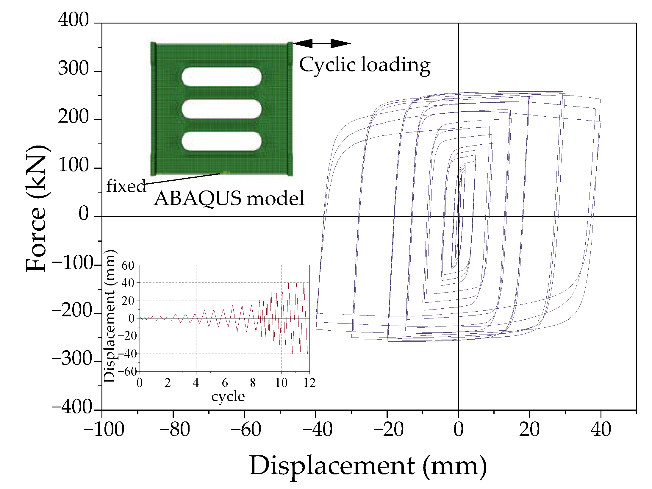
3.3. Verification of Numerical Model

The natural vibration characteristics of planar and spatial 3D frame structure are compared in order to verify the applicability of the planar 3D numerical model of this study. Table 3 shows the first three frequencies of two frame systems in the x-direction. It is evident that the natural frequencies of the planar 3D frame model are in good agreement with the spatial 3D model, except the third-order frequency, which has a large difference of 5%. However, the seismic response of low-rise buildings is mainly controlled by low-order modals. Therefore, the planar 3D frame structure modeling will be used to carry out the retrofit analysis of the damaged frame structure subjected to the unidirectional earthquake in order to reduce the computational time cost.

4. Modeling of MD-RC Frame
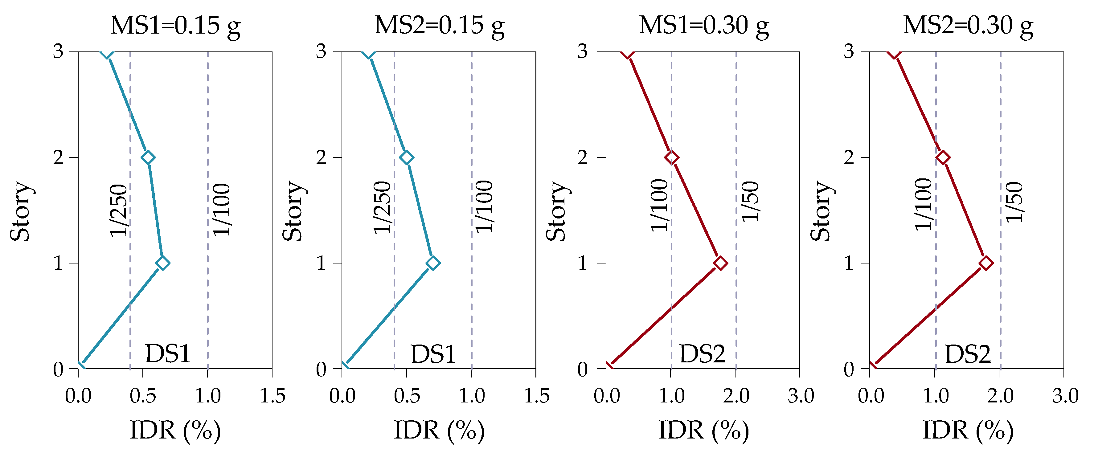
4.1. Input Motions

According to the methodology that is introduced in Section 2, the MD-RC frame models with different damage states (DS) can be obtained through the excitation of mainshocks with different intensities. Subsequently, the seismic performance analysis of the MD-RC frames with and without retrofitting schemes that are subjected to aftershocks is performed. For this purpose, the mainshock-aftershock (MS-AS) seismic sequences should be chosen before the retrofit analysis of the MD-RC frame. More specifically, in order to investigate the influence of earthquake type on retrofit effect, a widely used artificial seismic sequence method (i.e., randomized approach) introduced in literature [53] will be employed in this study. In the randomized approach, irrespective of the source distance (R) and earthquake magnitude (M), the ratios between the peak ground accelerations (PGA) for the two event cases are given by,
P G A ( 2 - E V E N T S ) P G A ( 1 E V E N T ) = P G A ( M 0.3010 ) P G A ( M ) = 10 0.49 + 0.23 ( M 6 0.3010 ) log R 2 + 8 2 0.0027 R 2 + 8 2 10 0.49 + 0.23 ( M 6 ) log R 2 + 8 2 0.0027 R 2 + 8 2 = 0.8526
Furthermore, in order to construct near-fault MS-AS seismic sequences, six recorded near-fault strong ground motions (include four pulse-like and two non-pulse-like ground motions) are selected from the Pacific Earthquake Engineering Research Center (PEER) NGA-West2 ground motion database as the input motions of the numerical simulation, according to the reference [54]. Table 4 summarizes the information of these selected recorded near-fault ground motions. In this table, the pulse-like ground motion recorded at SVC station in the 1989 Loma Prieta earthquake and JGB station in the 1994 Northridge earthquake are regarded as the mainshock ground motions (remark MS1 and MS2, respectively). Meanwhile, in order to investigate the impact of aftershock types, two pulse-like and two non-pulse-like motion records (i.e., do not contain strong velocity pulses.) are selected as the aftershock ground motions (remark AS1, AS2, AS3, and AS4, respectively). Furthermore, the peak values (i.e., PGA) of the mainshocks and aftershocks are unified as the same sign in order to avoid the polarity influence of MS-AS seismic sequence on the response and behavior of MD-RC frame. In this study, the peak values of mainshocks and aftershocks are uniformly set to be positive in the constructed artificial near-fault seismic sequence.

4.2. Numerical Modeling of MD-RC Frame

In order to obtain the numerical modeling of MD-RC frame, the initial damage state (DS) of MD-RC frame after mainshock should be first defined, as was mentioned previously. Severe damaged structures might be demolished and lose possibility of repair, according to the definition of structural damage state classification (see in Table 1). In addition, disaster investigation found that most of the earthquake-damaged structures are in a moderately damaged state or below [3]. To this end, two damage states (i.e., minor and moderate damage) of MD-RC frames are considered to investigate the damping effect of the retrofitting schemes on MD-RC frame under different damage levels in the present study. In the first damage state (remark DS1), the maximum IDR of intact structure should be in the range of 1/250 to 1/100. In the second damage state (remark DS2), the maximum IDR of intact structure should be in the range of 1/100 to 1/50. By the trial calculation, the intact structure will enter the above damage state (i.e., DS1 and DS2) when the PGA of the MS1 and MS2 mainshock were both 0.15 g and 0.30 g, respectively. Figure 5 presents the IDR distribution and damage limitation value under MS1 and MS2 mainshock excitation. In Figure 5, it is evident that the maximum IDR values of MD-RC frame fall within the range of minor and moderate damage under MS1 and MS2 mainshock excitation. In addition, all of the maximum IDR occur on the structural bottom floors, so the bottom floors must be retrofitted. Finally, four numerical models of MD-RC frame containing two damage states (i.e., DS1 and DS2) are obtained.
Table 5 lists the natural frequencies of the intact RC frame and four MD-RC frames. It is clear that the natural frequencies of the intact frame are significantly reduced, which indicates that the stiffness and strength of the structural materials have decreased to varying degrees.

5. Strengthening for MD-RC Frame Structure

5.1. Metallic Energy Dissipator

Soft steel damper (SSD) has high plastic deformation ability and low cycle fatigue resistance, which can enter the plastic energy dissipation stage earlier than structural members during an earthquake. Therefore, SSD could reduce the structural damage by dissipating part of the seismic input energy, and it has been widely used as the metallic energy dissipator (MED) for structural retrofitting [20,55]. Generally, typical SSD is designed to shear yielding mode (e.g., shear link or slit damper), because shear yielding dampers could provide higher initial stiffness under small earthquakes and significant energy dissipation potential during large earthquakes by inelastic deformation [28,30,55]. In addition, some studies have adopted opening-hole (or window) shaped SSD [30,35,55,56,57] or combined shear-and-flexural [44] SSD in order to limit stress concentration and out-of-plane buckling of SSD. Accordingly, a combined strip-shaped shear-and-flexural SSD (CSSD) MED has been designed and improved in this research by drawing on the above MEDs. This CSSD device consists of a strip-shaped SSD [35,55,57] (shear) and two flange plates (flexure) on the end of the SSD. A displacement-based design procedure has been used in order to design the capacity of the CSSD. The similar design process of these properties and capacity of the CSSD can be referred to following literature works [35,55,57]. The same capacity of the CSSD (i.e., designed according to maximum story yielding force) is employed for all stories in order to simplify the calculation. Figure 6 illustrates the configuration information of the CSSD device used in this research. As shown in Figure 6, all SSDs with an overall size of 400 × 400 mm2 and 12 mm thickness (ts) has been used in this study. Two flange plates of 12 mm thickness (tf) are welded to both ends of the SSD. Table 6 shows the material properties used in the CSSD device.
Because the CSSD device has two kinds of steel materials and complex geometric shapes, it is difficult to obtain a simplified calculation formula for computing the yield displacement, yield, and ultimate force of the CSSD device [55]. To this end, elastoplastic pseudo-static numerical analysis of the CSSD device under cyclic loadings is conducted while using the ABAQUS program to obtain the capacity of the CSSD device. Figure 7 shows the hysteretic curves of the CSSD numerical model under cyclic loadings. From this figure, it is clearly that CSSD device has larger initial stiffness and the hysteresis loop has a plump shape, which means that the CSSD has a higher ductility and a better energy dissipation performance after yielding.

5.2. Layout Scheme of CSSD Retrofitting Device

CSSD is usually installed between the braces and the beam, forming the CSSD brace (CSSDB) system [55]. In this study, the CSSDB system is composed of the CSSD device and chevron steel brace. During an earthquake, the CSSD device could provide significant energy dissipation potential through inelastic deformation and the steel braces could provide the lateral stiffness in order to prevent large deformation of the structural system. However, when subjected to strong ground motion, the brace buckling might lead to the degradation of lateral strength and stiffness of the structural system [58,59]. Thus, the braces should be designed to remain elastic for an axial force that is greater than corresponding to the failure strength of the CSSD device [60]. Hence, a simple H-shaped Beam (H-Beam, H150 × 150 × 10 × 7 mm) of steel bracing system is employed based on the design-criterion available in literature [35,55,57] in this study. In addition, three layout schemes (LS) of CSSDB systems are considered in this study in order to evaluate different CSSDB retrofitting schemes in terms of structural seismic performance. It should be noted that the same CSSD and steel braces are employed in these CSSDB systems. The specific LSs are introduced, as follows:
  • LS-1: Arranged CSSDB system on the bottom floor of MD-RC frame (Figure 8a);
  • LS-2: Arranged CSSDB system on the first and second floors of MD-RC frame (Figure 8b); and,
  • LS-3: Arranged CSSDB system on all floors of MD-RC frame (Figure 8c).
Figure 8 shows the layout information and detailed size of CSSDB system. In all of the CSSDB systems, the CSSD device is attached to the steel plates at the top and bottom using the welded connections. The steel plates and H-beams are made of Q345 steel with a Young’s modulus of 206 GPa, yielding strength of 345 MPa, and Poisson’s ratio of 0.3. In these retrofitting systems, the connections of steel plates and beam-column are welding. Rigid connection between CSSDB systems and concrete beam-column is assumed, and the influence of slippage and peeling between steel plates and concretes are neglected.

6. Analysis of Retrofit Effect of SSDB Systems

In this section, nonlinear dynamic time history analysis of MD-RC frames with and without retrofitting schemes are performed under four aftershocks for the purpose of evaluating the retrofit effect of the CSSDB systems on MD-RC frames under different layout schemes. Four MD-RC frames that contain two kinds damage states (DS1 and DS2) according to Section 4 are considered (i.e., corresponding MS amplitude is 0.15 g and 0.30 g, respectively). The AS amplitudes are scaled using the artificial seismic sequence method. In addition, the natural vibration characteristics, story displacement response, maximum IDR, and shock absorption rate are chosen as the indicators of structural seismic performance.

6.1. Natural Vibration Characteristic

The natural frequency of structure is an important parameter that reflects the dynamic characteristics of structures, and it is also related to the structural mass and stiffness. In general, during strong motions, concrete cracking and rebars yield might induce the stiffness of structure decrease and make the structure lose its bearing capacity, further leading to the change of natural vibration characteristics of structure. Therefore, the effects of CSSDB systems on the dynamic characteristics of MD-RC frames under different layout schemes are investigated in this section. For this purpose, frequency ratio (FR) factor is defined as FR = fr/fur, where fur is the frequency of MD-RC frame without retrofitting (i.e., un-retrofitted) and fr is the frequency of retrofitted MD-RC frame under three layout schemes. Figure 9 shows the natural frequencies ratio (FR) of retrofitted MD-RC frame and un-retrofitted MD-RC frame under DS1 and DS2 damage states. All FR values exceed 1.0, and the maximum value of FR is about 4.0 and the minimum value of FR is about 1.5, indicating that retrofitting systems have effectively improved the overall stiffness of MD-RC frames, as shown in Figure 9, intuitively. In addition, no matter which mainshock (i.e., MS1 and MS2) induced MD-RC frame, the FR value increase with the order of layout schemes (i.e., LS-1, LS-2, and LS-3). Especially for the first-order frequency, the amplitude of FR significantly increases. For the second- and third-order frequency, the changes in FR is not evident from LS-1 to LS-2, while both retrofitting schemes are different from LS-3. The results indicate that, with the increase of the number of retrofitted stories of MD-RC frame, the structural stiffness increases more obviously. Furthermore, for MD-RC frame with different damage states (i.e., DS1 and DS2), the natural frequency of moderate damaged structures (DS2) has significantly increased than that of minor damage (DS1), and with the decrease of modal order, the difference between DS1 and DS2 becomes increasingly obvious.

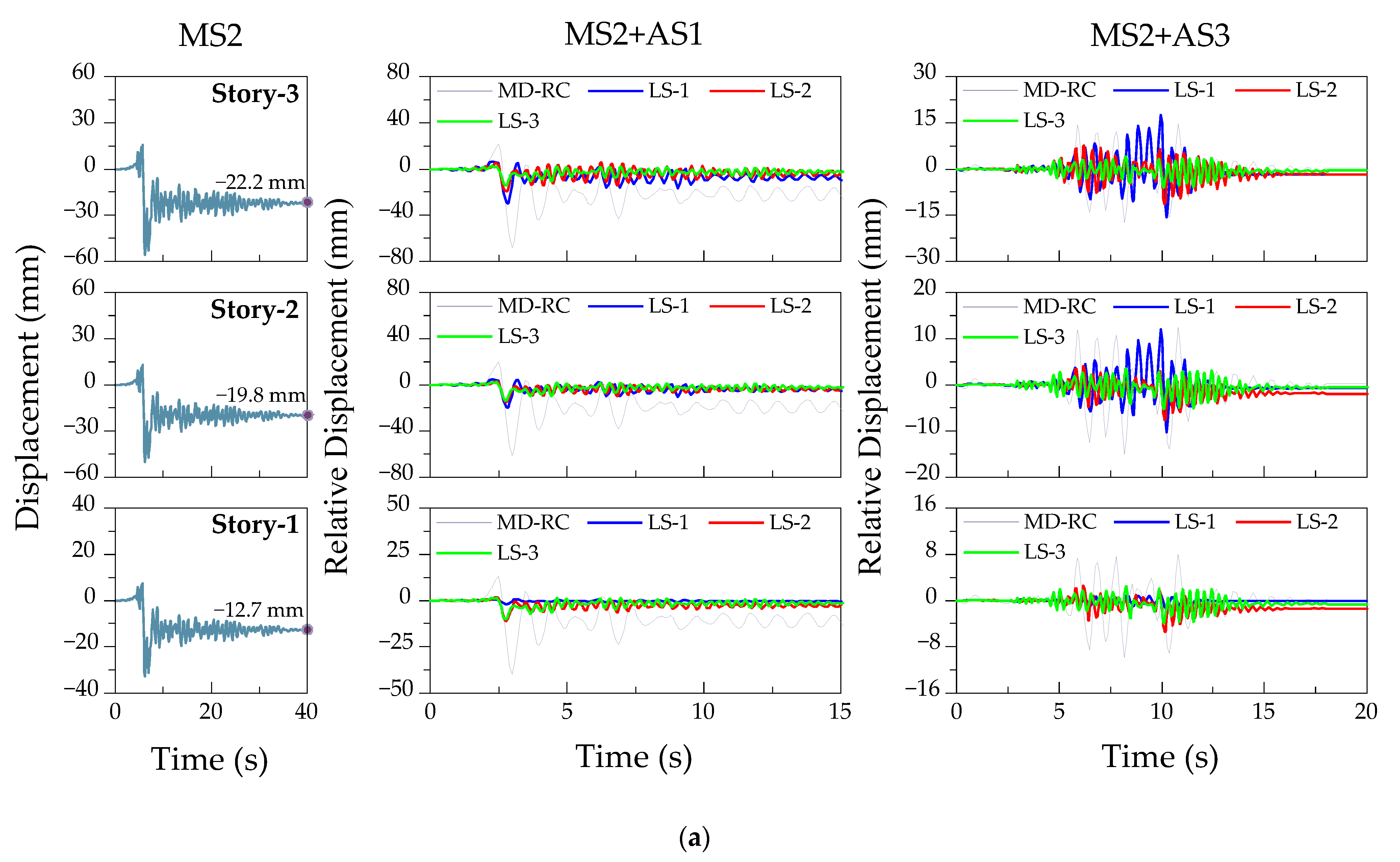
6.2. Story Displacement Response

In this section, story displacement response analysis of MD-RC frames with and without retrofitting schemes is carried out for the purpose of evaluating the retrofit effect of CSSDB systems under three layout schemes. As was mentioned previously, two damage states (i.e., DS1 and DS2) of the MD-RC frame after MS1 and MS2 excitations are considered. Meanwhile, four aftershocks, including near-fault pulse-like earthquakes (AS1 and AS2) and non-pulse-like earthquakes (AS3 and AS4), are selected as secondary excitation. As an example, Figure 10 and Figure 11 show the story displacement responses of retrofitted and un-retrofitted MD-RC frames subjected to AS1 and AS3 aftershock. In Figure 10 and Figure 11, the first column shows the displacement time histories of the intact frame under the mainshock excitations, the second and third columns show the relative displacement during aftershocks with respect to the residual displacement after mainshock excitations. From the overall view of Figure 10 and Figure 11, the peak story displacement of MD-RC frame after retrofitting significantly drops when compared with un-retrofitted MD-RC frame, which indicates that CSSDB systems can effectively control the peak displacement response of MD-RC frame. In addition, the peak story displacement of retrofitted MD-RC frame under AS1 aftershock decrease more significantly than that of AS3 aftershock. This result indicates CSSDB systems are more effective in controlling the dynamic response under pulse-like aftershock.
Similar to the above conclusion, the residual displacement of MD-RC frames under pulse-like aftershocks also decreases significantly. As the number of retrofitted floors increases (i.e., from LS-1 to LS-3), the decrease of residual displacement becomes more obvious. However, for non-pulse-like aftershocks, the residual displacement of MD-RC frame slightly and irregularly changes. Especially for moderate damaged (DS2) structures (see Figure 10b and Figure 11b), the retrofitting devices caused a greater permanent displacement for MD-RC frames. The reason may be that the retrofit of MD-RC frame will cause the redistribution of internal force in the structure, which results in the change of structural natural period and mode shape. When non-pulse-like aftershocks (containing rich high-frequency components) act, the presence of high-frequency components will excite high-order mode shapes of the MD-RC frame, resulting in a complex displacement response and permanent displacement. Especially when the mainshock damage state of MD-RC frame is more serious, this phenomenon is more obvious. Therefore, in the retrofit design of seismic-damaged structures, it is necessary to ensure that the retrofitted structure has a reasonable internal force distribution form. In addition, the above results also indicate that both of retrofitting schemes and aftershock types have a significant influence on displacement response of MD-RC frame. Furthermore, when comparing the mainshock damage state of MD-RC frame, the retrofit effect of CSSDB systems on the MD-RC frame with minor damage (DS1) is slightly better than that of moderate damage (DS2) no matter that aftershock types. A similar conclusion could be observed from the results of other aftershocks listed in Table 4.
Moreover, in order to quantitative assess the retrofit effect of CSSDB systems under three layout schemes on MD-RC frame, the peak displacement degradation percentage (PDDP) is defined by,
P D D P = d u r i d r i d u r i × 100 %
where, d u r i and d r i are the maximum displacement at ith story of un-retrofitted and retrofitted MD-RC frame, respectively. Table 7 presents PDDP values (%) of MD-RC frame under different retrofit schemes for each story. Intuitively, the mean values of PDDPs under pulse-like aftershocks (i.e., AS1 and AS2) are generally greater than that of non-pulse-like aftershocks (i.e., AS3 and AS4) no matter which retrofitting schemes. It indicates that CSSDB retrofitting systems have a better damping effect for pulse-like aftershocks than non-pulse-like aftershocks. In addition, when comparing the three layout schemes, LS-1 can significantly control the maximum bottom story displacement of MD-RC frame, and the maximum PDDP is as high as 94.8%. However, the effect of LS-1 on the other floors of MD-RC frame is obviously not as good as other retrofitting schemes. Especially for the top displacement response of MD-RC frame induced by MS2 mainshock decreased by −2.3% and −24% under AS3 and AS4 aftershock, respectively. This observation indicates that only retrofitting the bottom story (i.e., LS-1) of MD-RC frame might have an adverse effect on damaged frame, especially with non-pulse-like aftershocks excitation. This can be explained in that the structural beam-column joints have been various damaged after the mainshock excitation, especially the beam-column joints damage of structural bottom story will be more serious. In this case, only reinforcing the bottom story of MD-RC frame will cause the stiffness of the structural bottom story to be significantly increased when compared to the upper stories, which results in an obvious weak story mechanism, causing structural damage to move to the upper stories.
In addition, when comparing the results of LS-2 and LS-3, it can be found that most of the mean PDDPs under LS-3 are greater than LS-2, and the difference between them under pulse-like aftershocks is not higher than 17%, while the difference under the non-pulse-like aftershocks is up to 34%. For the LS-3 retrofitting scheme, the story displacements of the MD-RC frame have been effectively controlled and the peak displacement degradation range from 40~80%. In general, the greater numbers of reinforced structural stories, the more obvious retrofit effect, and the story number with the maximum PDDP is equal to the number of strengthened stories (i.e., bold font in Table 7). However, as the number of reinforced stories increases, both construction and economy will worsen, so it is necessary to seek a balance between economy and retrofit effect.

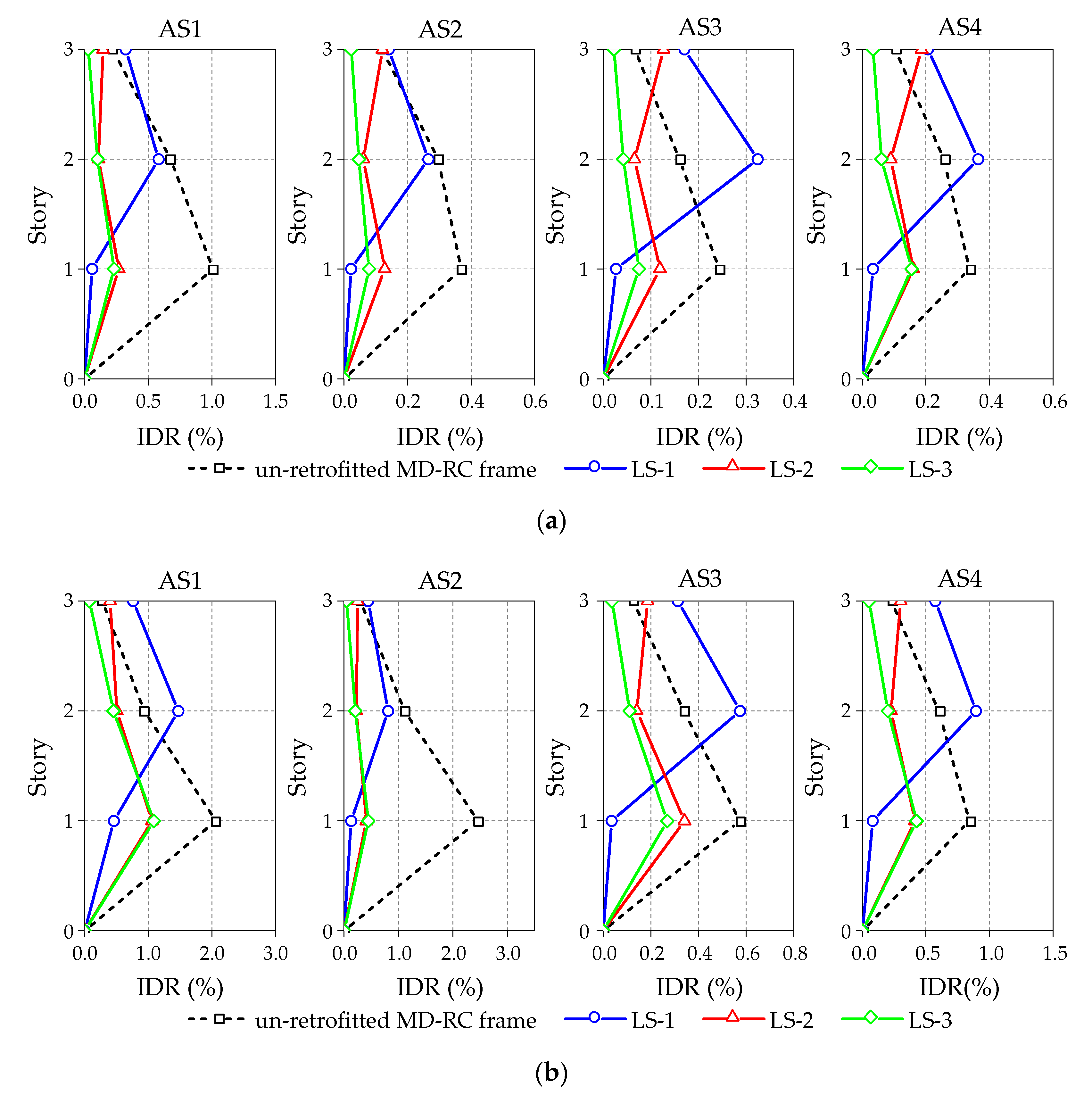
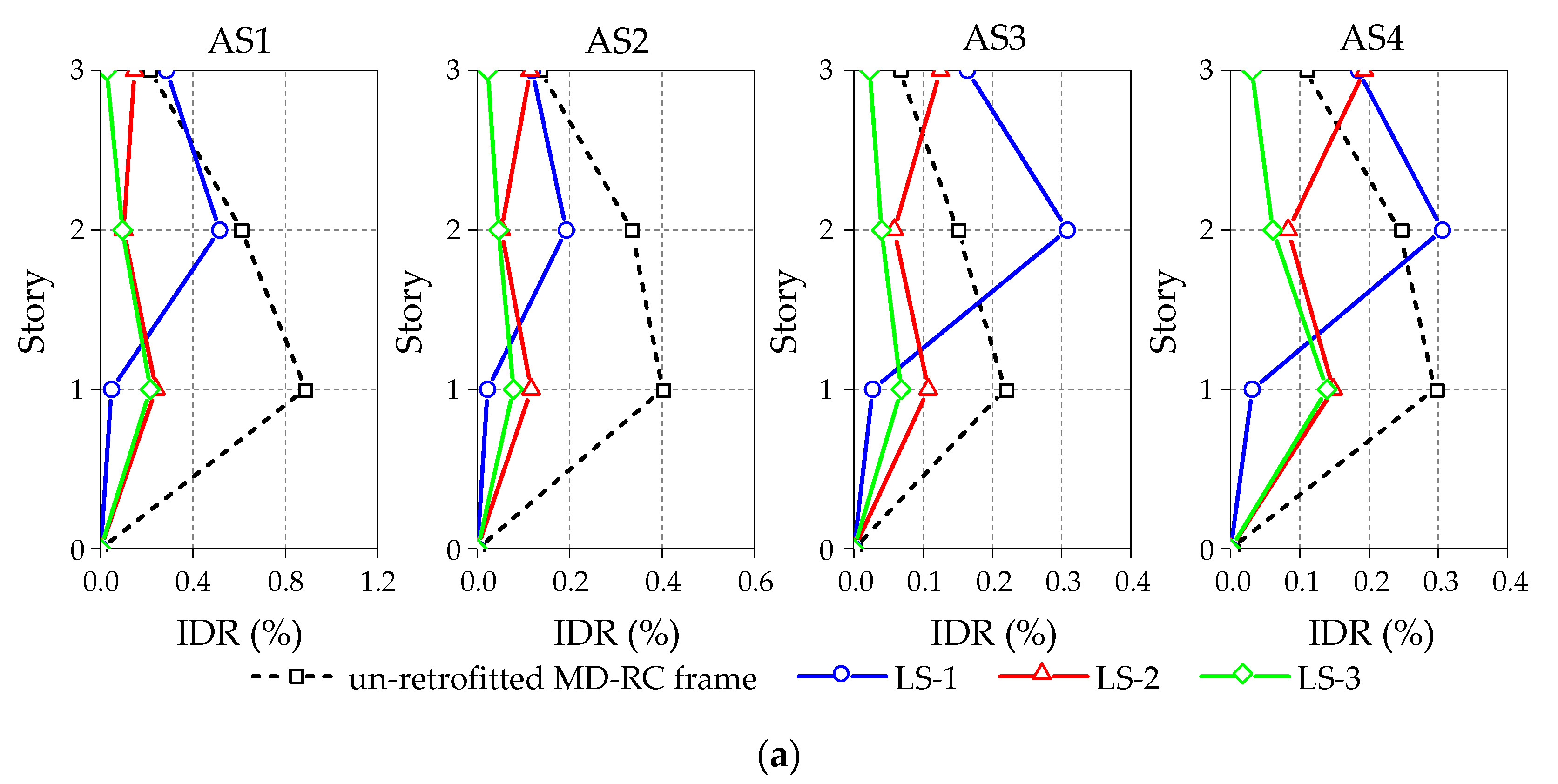
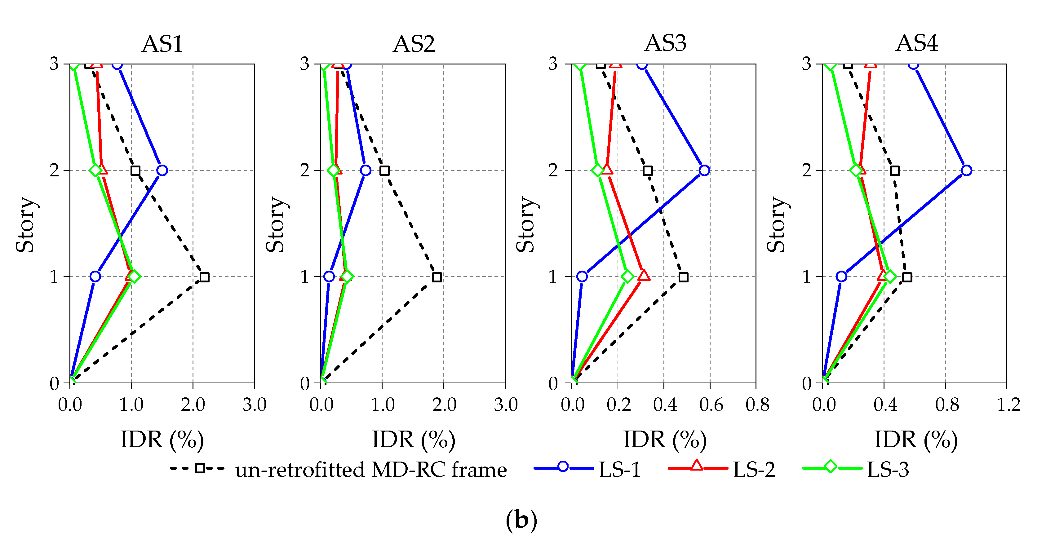
6.3. Interstory Drift Ratio (IDR)

IDR is one of the macroscopic parameters reflecting the structural story deformation and stiffness, and it is also one of the important indicators for judging the structural damage levels in engineering, as was mentioned previously. To this end, Figure 12 and Figure 13 shows the IDR distribution along with the height of MS1 and MS2 MD-RC frame with minor (DS1) and moderate (DS2) damage state before and after retrofitting under aftershocks excitations, respectively. From these figures, it can be initially observed that, in the case of LS-1, the maximum IDR reduction rate is up to 97.7% (first story) when compared with un-retrofitted MD-RC frame. LS-1 has a better performance in reducing the IDR of the first story of MD-RC frame structure as compared with other retrofitting schemes. However, the IDR reduction rate of second and third story of MD-RC frame is lower than other schemes. Especially for the non-pulse-like aftershocks scenarios, in some MD-RC frames retrofitted while using LS-1, the IDRs of second and third story even exceed those of un-retrofitted structure. The maximum IDR is 276.6% (third story) as large as the un-retrofitted case. It further illustrates that the LS-1 retrofitting scheme is not suitable for the retrofitting of MD-RC frame in this study. For the LS-2 retrofitting scheme, it is evident that the IDRs are lower than un-retrofitted MD-RC frame, except for the top story. Especially for the LS-3 retrofitting scheme, the IDR of each story of MD-RC frame are significantly reduced no matter the damage state. More specifically, the lowest reduction rate of IDR is 18.6%, and the highest reduction rate of IDR is up to 87.9%, which indicates that LS-3 plays a more positive effect on the seismic performance of MD-RC frame as compared with other retrofitting schemes. Moreover, when comparing the results of LS-2 and LS-3, although LS-2 does not reinforce the top story of MD-RC frame, the maximum IDR of the first and second story are relatively close under LS-2 and LS-3 schemes. Although the IDR of the top story under the LS-2 retrofitting scheme exceeds other stories, the maximum IDRs are significantly lower than the un-retrofitted case. Therefore, with the comprehensive consideration of economy and installation portability, the engineering applicability of LS-2 scheme is better than LS-3 scheme.
In addition, to quantitatively analyze the retrofit effect of these CSSDB systems on MD-RC frame, in this study the shock absorption rate (SAR) index is used and it is defined as,
S A R = M I D R u r M I D R r M I D R u r × 100 %
where, M I D R u r and M I D R r are the maximum IDR (MIDR) of un-retrofitted and retrofitted MD-RC frame, respectively.
Table 8 summarizes the MIDR and SAR values of MD-RC frame before and after retrofitting under different LSs. From this table, it is evident that the MIDR of retrofitted MD-RC frame has dropped significantly for LS-2 and LS-3 schemes, the maximum drop is nearly 5.6 times. However, for the LS-1 scheme, similar to the previous observations, the MIDRs of some retrofitted MD-RC frames even exceed that of un-retrofitted structures, especially under non-pulse-like aftershocks. More specifically, for the minor damage MD-RC frame, the MIDR under LS-1 scheme is usually 2.0~4.0 times as large as that of LS-2 and LS-3 schemes; for the moderate damage MD-RC frame, the MIDR under LS-1 scheme is usually 1.4~2.2 times as large as that of LS-2 and LS-3 schemes. In terms of SAR; it is evident that the SAR under LS-1 is usually the lowest and even negative under non-pulse-like aftershocks, with a maximum SAR of −74.1%. Obviously, it is not sufficient to carry out only retrofit on structural bottom story for MD-RC frame due to the randomness and uncertainty of ground motion. Furthermore, no matter the mainshock excitation or mainshock damage state, the SAR under LS-2 and LS-3 schemes ranges from 47.1% to 83.3% during pulse-like aftershocks, and ranges from 18.5% to 68.2% during non-pulse-like aftershocks, which further proves that the retrofit effect of CSSDB systems under pulse-like aftershocks is significantly better than that of the non-pulse-like. Overall, there is no noticeable difference in the SAR of MD-RC frames that were retrofitted by LS-2 and LS-3 schemes. However, the LS-2 scheme is more suitable for the retrofit of MD-RC frame in this research, due to the fact that LS-2 scheme retrofits less stories when compared with LS-3 scheme.

7. Conclusions

This paper mainly conducted the post-earthquake retrofitting analysis of the mainshock-damaged RC (MD-RC) frame while using soft steel damper as the passive energy dissipation device under near-fault aftershocks excitation. Firstly, a numerical evaluation framework for post-earthquake retrofitting of the MD-RC frame was proposed. Subsequently, three retrofitting schemes based on soft steel dampers and steel brace were designed for the MD-RC frame structure. Finally, through the nonlinear dynamic time history analysis of the MD-RC frame structure with and without retrofitting schemes, the retrofit effect of the three retrofitting schemes on the MD-RC frame was evaluated, and some conclusions were obtained, as follows:
(1)
The CSSDB retrofitting systems have effectively improved the natural frequency (stiffness) of the MD-RC frame. The first-order natural frequency has a largest increase, with a maximum increase of nearly four times and the second and third-order natural frequencies have a maximum increase of three times. In addition, with the increase of the number of retrofitted stories of the MD-RC frame, the structural stiffness increases more obviously. The natural frequency of moderate damaged structures has increased significantly than that of minor damage. Especially for the first-order mode, the frequency increase in moderately damaged structures is more significant.
(2)
The reduction of the maximum story displacement and residual displacement of the retrofitted MD-RC frame under pulse-like aftershocks is more obvious than that under non-pulse-like aftershocks, which indicates that aftershock type has an important influence on the retrofit effect of CSSDB systems for the MD-RC frame. In addition, the retrofit effect of CSSDB systems on the MD-RC frame with minor damage is slightly better than that of the structure with severe damage, indicating that the damage state of the MD-RC frame should also be considered when carrying out the seismic retrofitting design of earthquake-damaged structures.
(3)
In the case of LS-1 scheme, the maximum IDR reduction rate is up to 97.7% (first story) when compared with un-retrofitted MD-RC frame. LS-1 scheme has better performance in reducing the IDR of the first story of MD-RC frame structure as compared with the other retrofitting schemes. However, the IDR reduction rate of the second and third story of MD-RC frame is lower than other schemes. Especially for the non-pulse-like aftershocks scenarios, in some MD-RC frames that were retrofitted using LS-1 scheme, and the IDRs of second and third story even exceed those of un-retrofitted MD-RC frame. The maximum IDR is 276.6% (third story) as large as the un-retrofitted case. For the LS-2 scheme, it is evident that the IDRs are lower than un-retrofitted MD-RC frame, except for the top story. Especially for LS-3, the IDR of each story of the MD-RC frame are significantly reduced no matter which damage state. Therefore, it can be seen that LS-3 plays a more positive effect on the seismic performance of the MD-RC frame.
(4)
The shock absorption rate (SAR) under only retrofitting bottom story (i.e., LS-1) of the MD-RC frame is lower than that of retrofitting more stories, and the difference is approximately 1.2~2.0 times lower than other retrofitting schemes for pulse-like aftershocks. However, under non-pulse-like aftershocks, the SAR of only retrofitting the structural bottom story is negative with a maximum amplitude of −74.1%. It indicates that only retrofitting the bottom story of the structure is not usually sufficient, especially for the non-pulse-like aftershocks., In addition, there is no noticeable difference in the SAR of MD-RC frames between retrofitting two stories (LS-2) and three stories (LS-3). In contrast, LS-2 might have a better economy and installation portability in engineering applications in this research.
It should be noted that the above conclusions are based on the results of a three-story building and, when only one SSD retrofitting configuration is used, the influence of the geometric sizes of SSD device on the retrofit effect are ignored in this study. In addition, a limited set of earthquakes inputs is considered in the numerical investigation (i.e., two mainshocks and four aftershocks earthquakes). However, due to the randomness of a future earthquake, the main conclusions of the present study are only valid for the examined earthquake scenarios. Therefore, the generalization of these conclusions for other buildings and more seismic inputs still needs greater investigations. Moreover, a more thorough life-cycle cost analysis needs to be conducted in order to select the most optimal retrofitting scheme for an earthquake-damaged building.

Author Contributions

Conceptualization, F.Y. and G.W.; methodology, F.Y. and G.W.; software, F.Y. and M.L.; validation, F.Y. and M.L.; investigation, F.Y. and G.W.; writing—original draft preparation, F.Y.; writing—review and editing, F.Y. and G.W. All authors have read and agreed to the published version of the manuscript.

Funding

This research was funded by the Ministry of Science and Technology of China (National Key R&D Program), grant number 2018YFD1100405 and the National Natural Science Foundation of China, grant number 51578113.

Institutional Review Board Statement

Not applicable.

Informed Consent Statement

Not applicable.

Data Availability Statement

The ground-motion records used in this study were retrieved from the PEER NGA-West2 database (http://ngawest2.berkeley.edu, last accessed December 2018). The results presented in this study are available on request from the corresponding author. The data are not publicly available due to the reason that the authors are conducting further analysis on the same structural model.

Acknowledgments

The authors would like to thank Wang Rui and Ding Yang for their suggestions on numerical analysis and paper writing. The authors also would like to thank the editor-in-chief and four anonymous reviewers for their constructive comments that have helped improve this paper substantially.

Conflicts of Interest

The authors declare no conflict of interest.

References

  1. Liu, R.Y.; Yang, Y. Experimental study on seismic performance of seismic-damaged RC frame retrofitted by prestressed steel strips. Bull. Earthq. Eng. 2020, 18, 6475–6486. [Google Scholar] [CrossRef]
  2. Di Sarno, L. Effects of multiple earthquakes on inelastic structural response. Eng. Struct. 2013, 56, 673–681. [Google Scholar] [CrossRef]
  3. Tsinghua University; Southwest Jiaotong University; Beijing Jiaotong University. Analysis of Building Damage in Wenchuan Earthquake. J. Build. Struct. 2008, 29, 1–9. (In Chinese) [Google Scholar]
  4. Dong, Y.R.; Xu, Z.D.; Li, Q.Q.; Xu, Y.S.; Chen, Z.H. Seismic behavior and damage evolution for retrofitted RC frames using haunch viscoelastic damping braces. Eng. Struct. 2019, 199, 109583. [Google Scholar] [CrossRef]
  5. Di Ludovico, M.; Prota, A.; Manfredi, G.; Cosenza, E. Seismic strengthening of an under-designed RC structure with FRP. Earthq. Eng. Struct. Dyn. 2008, 37, 141–162. [Google Scholar] [CrossRef]
  6. Sasmal, S.; Novák, B.; Ramanjaneyulu, K. Numerical analysis of fiber composite-steel plate upgraded beam-column sub-assemblages under cyclic loading. Compos. Struct. 2011, 93, 599–610. [Google Scholar] [CrossRef]
  7. Sasmal, S.; Khatri, C.P.; Karusala, R. Numerical simulation of performance of near-surface mounted FRP-upgraded beam–column sub-assemblages under cyclic loading. Struct. Infrastruct. Eng. 2015, 11, 1012–1027. [Google Scholar] [CrossRef]
  8. Mostofinejad, D.; Hosseini, S.M.; Tehrani, B.N.; Eftekhar, M.R.; Dyari, M. Innovative warp and woof strap (WWS) method to anchor the FRP sheets in strengthened concrete beams. Construct. Build. Mater. 2019, 218, 351–364. [Google Scholar] [CrossRef]
  9. Le-Trung, K.; Lee, K.; Lee, J.; Lee, D.H.; Woo, S. Experimental study of RC beam-column joints strengthened using CFRP composites. Compos. B Eng. 2010, 41, 76–85. [Google Scholar] [CrossRef]
  10. Singh, V.; Bansal, P.P.; Kumar, M.; Kaushik, S.K. Experimental studies on strength and ductility of CFRP jacketed reinforced concrete beam-column joints. Construct. Build. Mater. 2014, 55, 194–201. [Google Scholar] [CrossRef]
  11. Esmaeeli, E.; Barros, J.A.; Sena-Cruz, J.; Fasan, L.; Prizzi, F.R.L.; Melo, J.; Varum, H. Retrofitting of interior RC beam-column joints using CFRP strengthened SHCC: Cast-in-Place Solution. Compos. Struct. 2015, 122, 456–467. [Google Scholar] [CrossRef] [Green Version]
  12. Hsieh, C.T.; Lin, Y. Detecting debonding flaws at the epoxy-concrete interfaces in near-surface mounted CFRP strengthening beams using the impact-echo method. NDT E Int. 2016, 83, 1–13. [Google Scholar] [CrossRef]
  13. Prado, D.M.; Araujo, I.D.G.; Haach, V.G.; Carrazedo, R. Assessment of shear damaged and NSM CFRP retrofitted reinforced concrete beams based on modal analysis. Eng. Struct. 2016, 129, 54–66. [Google Scholar] [CrossRef]
  14. Reinhorn, A.M.; Li, C.; Constantinou, M.C. Experimental and Analytical Investigation of Seismic Retrofit of Structures with Supplemental Damping: Part 1-Fluid Viscous Damping Devices; Report No. NCEER-95-0001; National Center for Earthquake Engineering Research: Buffalo, NY, USA, 1995. [Google Scholar]
  15. Lin, W.H.; Anil, K.C. Earthquake response of elastic SDF systems with non-linear fluid viscous dampers. Earthq. Eng. Struct. Dyn. 2002, 31, 1623–1642. [Google Scholar] [CrossRef]
  16. Goel, R.K. Effects of supplemental viscous damping on seismic response of asymmetric-plan systems. Earthq. Eng. Struct. Dyn. 1998, 27, 125–141. [Google Scholar] [CrossRef]
  17. Di Sarno, L.; Manfredi, G. Experimental tests on full-scale RC unretrofitted frame and retrofitted with buckling-restrained braces. Earthq. Eng. Struct. Dyn. 2012, 41, 315–333. [Google Scholar] [CrossRef] [Green Version]
  18. Di Sarno, L.; Manfredi, G. Seismic retrofitting with buckling restrained braces: Application to an existing non-ductile RC framed building. Soil Dyn. Earthq. Eng. 2010, 30, 1279–1297. [Google Scholar] [CrossRef]
  19. Takeuchi, T.; Nakamura, H.; Kimura, I.; Hasegawa, H.; Saeki, E.; Watanabe, A. Buckling Restrained Braces and Damping Steel Structures. U.S. Patent US20050055968A1, 17 March 2005. [Google Scholar]
  20. Vafaei, M.; Sheikh, A.M.O.; Alih, S.C. Experimental study on the efficiency of tapered strip dampers for the seismic retrofitting of damaged non-ductile RC frames. Eng. Struct. 2019, 199, 109601. [Google Scholar] [CrossRef]
  21. Sahoo, D.R.; Rai, D.C. Design and evaluation of seismic strengthening techniques for reinforced concrete frames with soft ground story. Eng. Struct. 2013, 56, 1933–1944. [Google Scholar] [CrossRef]
  22. Oinam, R.M.; Sahoo, D.R. Seismic rehabilitation of damaged reinforced concrete frames using combined metallic yielding passive devices. Struct. Infrastruct. Eng. 2017, 13, 816–830. [Google Scholar] [CrossRef]
  23. Lee, C.H.; Ryu, J.; Kim, D.H.; Ju, Y.K. Improving seismic performance of non-ductile reinforced concrete frames through the combined behavior of friction and metallic dampers. Eng. Struct. 2018, 172, 304–320. [Google Scholar] [CrossRef]
  24. Morelli, F.; Piscini, A.; Salvatore, W. Seismic behavior of an industrial steel structure retrofitted with self-centering hysteretic dampers. J. Construct. Steel Res. 2017, 139, 157–175. [Google Scholar] [CrossRef]
  25. Kelly, J.M.; Skinner, R.I.; Heine, A.J. Mechanisms of energy absorption in special devices for use in earthquake resistant structures. Bull. N. Z. Soc. Earthq. Eng. 1972, 5, 63–88. [Google Scholar]
  26. Skinner, R.I.; Kelly, J.M.; Heine, A.J. Hysteretic dampers for earthquake-resistant structures. Earthq. Eng. Struct. Dyn. 1974, 3, 287–296. [Google Scholar] [CrossRef]
  27. Durucan, C.; Dicleli, M. Analytical study on seismic retrofitting of reinforced concrete buildings using steel braces with shear link. Eng. Struct. 2010, 32, 2995–3010. [Google Scholar] [CrossRef]
  28. Rai, D.C.; Annam, P.K.; Pradhan, T. Seismic testing of steel braced frames with aluminum shear yielding dampers. Eng. Struct. 2013, 46, 737–747. [Google Scholar] [CrossRef]
  29. Dusicka, P.; Itani, A.M.; Buckle, I.G. Cyclic behavior of shear links of various grades of plate steel. J. Struct. Eng. 2010, 136, 370–378. [Google Scholar] [CrossRef]
  30. Nuzzo, I.; Losanno, D.; Caterino, N.; Serino, G.; Rotondo, L.M.B. Experimental and analytical characterization of steel shear links for seismic energy dissipation. Eng. Struct. 2018, 172, 405–418. [Google Scholar] [CrossRef]
  31. Hitaka, T.; Matsui, C. Experimental study on steel shear wall with slits. J. Struct. Eng. 2003, 129, 586–595. [Google Scholar] [CrossRef]
  32. Chan, R.W.; Albermani, F. Experimental study of steel slit damper for passive energy dissipation. Eng. Struct. 2008, 30, 1058–1066. [Google Scholar] [CrossRef]
  33. Tagawa, H.; Yamanishi, T.; Takaki, A.; Chan, R.W. Cyclic behavior of seesaw energy dissipation system with steel slit dampers. J. Construct. Steel Res. 2016, 117, 24–34. [Google Scholar] [CrossRef]
  34. Saffari, H.; Hedayat, A.A.; Nejad, M.P. Post-Northridge connections with slit dampers to enhance strength and ductility. J. Construct. Steel Res. 2013, 80, 138–152. [Google Scholar] [CrossRef]
  35. Li, H.; Li, G. Experimental study of structure with “dual function” metallic dampers. Eng. Struct. 2007, 29, 1917–1928. [Google Scholar] [CrossRef]
  36. Martinez-Romero, E. Experiences on the use of supplementary energy dissipators on building structures. Earthq. Spectra 1993, 9, 581–625. [Google Scholar] [CrossRef]
  37. Perry, C.L.; Fierro, E.A.; Sedarat, H.; Scholl, R.E. Seismic upgrade in San Francisco using energy dissipation devices. Earthq. Spectra 1993, 9, 559–579. [Google Scholar] [CrossRef]
  38. Tsai, K.C.; Chen, H.W.; Hong, C.P.; Su, Y.F. Design of steel triangular plate energy absorbers for seismic-resistant construction. Earthq. Spectra 1993, 9, 505–528. [Google Scholar] [CrossRef]
  39. Mahjoubi, S.; Maleki, S. Seismic performance evaluation and design of steel structures equipped with dual-pipe dampers. J. Construct. Steel Res. 2016, 122, 25–39. [Google Scholar] [CrossRef] [Green Version]
  40. Maleki, S.; Bagheri, S. Pipe damper, Part II: Application to bridges. J. Construct. Steel Res. 2010, 66, 1096–1106. [Google Scholar] [CrossRef]
  41. Tena-Colunga, A.; Pérez-Moreno, D. Seismic upgrading of a nine-story building at Mexico City’s lake-bed zone using U-Shaped energy dissipation devices. In Proceedings of the 9th International Seminar on Earthquake Prognostics, San Jose, Costa Rica, 19–23 September 1994; Volume 10, pp. 1991–9684. [Google Scholar]
  42. Tena-Colunga, A.; Del Valle, E.; Pe’rez-Moreno, D. Issues on the seismic retrofit of a building near resonant response and structural pounding. Earthq. Spectra 1996, 12, 567–597. [Google Scholar] [CrossRef]
  43. Rahnavard, R.; Rebelo, C.; Craveiro, H.D.; Napolitano, R. Numerical investigation of the cyclic performance of reinforced concrete frames equipped with a combination of a rubber core and a U-shaped metallic damper. Eng. Struct. 2020, 225, 111307. [Google Scholar] [CrossRef]
  44. Sahoo, D.R.; Singhal, T.; Taraithia, S.S.; Saini, A. Cyclic behavior of shear-and-flexural yielding metallic dampers. J. Construct. Steel Res. 2015, 114, 247–257. [Google Scholar] [CrossRef]
  45. Gandelli, E.; Taras, A.; Distl, J.; Quaglini, V. Seismic retrofit of hospitals by means of hysteretic braces: Influence on acceleration-sensitive non-structural components. Front. Built Environ. 2019, 5, 100. [Google Scholar] [CrossRef]
  46. Gandelli, E.; Chernyshov, S.; Distl, J.; Dubini, P.; Weber, F.; Taras, A. Novel adaptive hysteretic damper for enhanced seismic protection of braced buildings. Soil Dyn. Earthq. Eng. 2020, 141, 106522. [Google Scholar] [CrossRef]
  47. ABAQUS. Version ABAQUS. 6.14 Document; ABAQUS Inc.: Johnston, RI, USA, 2014. [Google Scholar]
  48. Imjai, T.; Setkit, M.; Garcia, R.; Figueiredo, F.P. Strengthening of damaged low strength concrete beams using PTMS or NSM techniques. Case Stud. Construct. Mater. 2020, 13, e00403. [Google Scholar] [CrossRef]
  49. Ministry of Housing and Urban-Rural Development of the People’s Republic of China. Code for Seismic Design of Buildings; GB50011-2010; Ministry of Housing and Urban-Rural Development of the People’s Republic of China: Beijing, China, 2010. (In Chinese) [Google Scholar]
  50. Ministry of Housing and Urban-Rural Development of the People’s Republic of China. Code for Design of Concrete Structures; GB50010-2010; Ministry of Housing and Urban-Rural Development of the People’s Republic of China: Beijing, China, 2010. (In Chinese) [Google Scholar]
  51. Ministry of Housing and Urban-Rural Development of the People’s Republic of China. Load Code for the Design of Building Structures; GB50009-2010; Ministry of Housing and Urban-Rural Development of the People’s Republic of China: Beijing, China, 2012. (In Chinese) [Google Scholar]
  52. ABAQUS. ABAQUS Theory Manual, “Version 6.13”; ABAQUS Inc.: Johnston, RI, USA, 2014. [Google Scholar]
  53. Hatzigeorgiou, G.D.; Beskos, D.E. Inelastic displacement ratios for SDOF structures subjected to repeated earthquakes. Eng. Struct. 2009, 31, 2744–2755. [Google Scholar] [CrossRef]
  54. Yang, F.; Wang, G.; Ding, Y. Damage demands evaluation of reinforced concrete frame structure subjected to near-fault seismic sequences. Nat. Hazards 2019, 97, 841–860. [Google Scholar] [CrossRef]
  55. Li, H.N.; Li, G.; Li, Z.; Xing, F. Earthquake-Resistant design of reinforced concrete frame with metallic dampers of “dual function”. J. Build. Struct. 2007, 28, 36–43. (In Chinese) [Google Scholar]
  56. Nuzzo, I.; Losanno, D.; Serino, G.; Bozzo, L. A Seismic-resistant Precast r.c. system equipped with shear link dissipators for residential buildings. In Proceedings of the Second International Conference on Advances in Civil, Structural and Environmental Engineering-ACSEE 2014, Zurich, Switzerland, 25–26 October 2014; Volume 2. [Google Scholar]
  57. Li, G. Theoretical and Experimental Research on the Structure with New Type of Metallic Dampers. Ph.D. Thesis, Dalian University of Technology, Dalian, China, 2006. (In Chinese). [Google Scholar]
  58. Dicleli, M.; Mehta, A. Seismic retrofitting of chevron-braced steel frames based on preventing buckling instability of braces. Int. J. Struct. Stab. Dyn. 2009, 9, 333–356. [Google Scholar] [CrossRef]
  59. Li, G.; Dong, Z.Q.; Li, H.N. Simplified collapse-prevention evaluation for the reserve system of low-ductility steel concentrically braced frames. J. Struct. Eng. 2018, 144, 04018071. [Google Scholar] [CrossRef]
  60. Sahoo, D.R.; Rai, D.C. Seismic strengthening of non-ductile reinforced concrete frames using aluminum shear links as energy-dissipation devices. Eng. Struct. 2010, 32, 3548–3557. [Google Scholar] [CrossRef]
Figure 1. Post-earthquake retrofitting evaluation framework of the mainshock-damaged reinforced concrete (MD-RC) frame.
Applsci 11 00841 g001
Figure 2. Geometries and reinforcement details for RC frame (all dimensions in mm): (a) plan view; (b) reinforcement details of the beam and column section; (c) elevation view.
Applsci 11 00841 g002
Figure 3. The planar three-dimensional (3D) numerical model of intact RC frame.
Applsci 11 00841 g003
Figure 4. Stress-strain relations under uniaxial cycle loading of concrete damage plasticity (CDP) model.
Applsci 11 00841 g004
Figure 5. IDR distribution and damage limitation value under MS1 and MS2 mainshock excitation.
Applsci 11 00841 g005
Figure 6. Configuration of the combined soft steel dampers (CSSD) device (all dimensions in mm): (a) soft steel damper (SSD); (b) flange; (c) CSSD device.
Applsci 11 00841 g006
Figure 7. Hysteresis loop of the CSSD numerical model under cyclic loadings.
Applsci 11 00841 g007
Figure 8. Layout schemes (ac) and detailed size (d) of CSSDB systems for MD-RC frame (all dimensions in mm).
Applsci 11 00841 g008
Figure 9. Frequency ratios (FR) of DS1 and DS2 damage states MD-RC frames with and without retrofitted by three layout schemes: (a) MS1 mainshock; and, (b) MS2 mainshock.
Applsci 11 00841 g009
Figure 10. Displacement time histories of DS1 (a) and DS2 (b) damage states MD-RC frame due to MS1 mainshock before and after retrofitting subjected to AS1 and AS3 aftershocks.
Applsci 11 00841 g010aApplsci 11 00841 g010b
Figure 11. Displacement time histories of DS1 (a) and DS2 (b) damage states MD-RC frame due to MS2 mainshock before and after retrofitting subjected to AS1 and AS3 aftershocks.
Applsci 11 00841 g011aApplsci 11 00841 g011b
Figure 12. IDR distribution of MS1 MD-RC frame with DS1 (a) and DS2 (b) damage state before and after retrofitting.
Applsci 11 00841 g012
Figure 13. IDR distribution of MS2 MD-RC frame with DS1 (a) and DS2 (b) damage state before and after retrofitting.
Applsci 11 00841 g013aApplsci 11 00841 g013b
Table 1. Structural damage states corresponding to the interstory drift ratio (IDR) limit values.
Damage StatesDescriptionIDR 1 (%)
NeglectedNo damage or localized minor cracking<0.4
Minor damageSlight cracking throughout0.4~1.0
Moderate damageSevere cracking, localized spalling1.0~2.0
Severe damageCrushing of concrete, reinforcement exposed2.0~4.0
CollapseCollapsed>4.0
1 IDR: Maximum interstory drift ratio.
Table 2. Material input parameters of concretes and rebars in this study.
Material TypesConstitutive ModelInput ParametersValues
Concretes (C30)CDPMass density, ρc (kg/m3)2400
Elastic modulus, Ec (MPa)30,000
Poisson’s ratio, ν0.2
Compressive strength, fc (MPa)20.1
Tensile strength, ft (MPa)2.01
Rebars HRB335 (HPB300)Bilinear ElastoplasticMass density, ρs (kg/m3)7830
Elastic modulus, Es (GPa)200 (210)
Poisson’s ratio, ν0.3
Yield Strength, fy (MPa)335 (300)
Ultimate strength, fu (MPa)450 (345)
Table 3. The first three frequencies of the planar and spatial 3D frame model.
ModeNatural Frequency (Hz)
Planar 3D Frame ModelSpatial 3D Frame ModelError (%)
11.231.240.80
24.054.001.25
37.036.714.77
Table 4. Information of selected recorded near-fault ground motions in this study.
No.EarthquakeYearMw 1Station and Comp. 2RRUP3VS304Pulse
MS1Loma Prieta19896.9SVC2709.3347.9yes
MS2Northridge19946.7JGB0225.4525.8yes
AS1Northridge19946.7RRS2286.5282.3yes
AS2Imperial Valley19796.5E062301.4203.2yes
AS3Gazli, USSR19766.8GAZ0905.5259.6no
AS4Loma Prieta19896.9BRN09010.7462.2no
1 Moment magnitude; 2 Ground motion components; 3 Closest distance to rupture plane, unit: km; 4 Average shear velocity of top 30 m, unit: m/s.
Table 5. Natural frequencies of the intact RC frame and MD-RC frame (Hz).
ModeIntact StructureAfter MS1After MS2
DS1DS2DS1DS2
11.230.990.761.110.93
24.053.623.133.803.46
37.046.395.866.656.22
Table 6. Material properties of the CSSD device in this study.
Material TypesElastic Modulus Es (GPa)Yield Strength fy (MPa)Ultimate Strength fu (MPa)
SSD210100350
Flange210235441
Table 7. Peak displacement degradation percentage (PDDP) (%) of MD-RC frames under different retrofitting schemes.
MS DSStoryAS1AS2AS3AS4
LS-1LS-2LS-3LS-1LS-2LS-3LS-1LS-2LS-3LS-1LS-2LS-3
DS1(MS1)193.872.576.593.964.076.689.945.259.291.049.142.1
266.776.479.160.770.778.627.349.264.741.556.451.8
355.772.679.950.560.679.43.434.765.223.644.355.2
Mean72.173.878.568.465.178.240.243.063.052.049.949.7
DS1(MS2)194.872.275.294.369.479.787.244.760.390.345.652.8
267.576.378.374.175.681.620.549.364.745.851.963.4
356.271.879.265.167.182.12.333.065.630.835.166.8
Mean72.873.477.677.870.781.135.142.363.555.644.261.0
DS2(MS1)175.244.141.193.682.581.893.827.025.988.338.531.2
241.045.344.576.883.182.242.032.233.139.946.043.1
326.040.146.768.980.982.521.625.535.818.742.447.7
Mean47.443.244.179.882.282.252.528.231.649.042.340.7
DS2(MS2)179.750.852.192.177.977.290.634.649.474.726.618.6
247.851.754.573.379.078.033.540.754.56.734.833.8
333.746.256.565.176.578.510.534.156.724.022.838.2
Mean53.749.654.476.877.877.944.936.553.519.128.130.2
Table 8. Maximum IDR and shock absorption rate (SAR) of MD-RC frame before and after retrofitting.
AftershocksSchemesDS1 (MS1)DS1 (MS2)DS2 (MS1)DS2 (MS2)
MIDRSAR (%)MIDRSAR (%)MIDRSAR (%)MIDRSAR (%)
AS1 (Pulse-like)UR0.0101 0.0089 0.0206 0.0219
LS-10.005842.40.005241.80.014728.60.015031.4
LS-20.002773.50.002473.00.010648.80.010054.4
LS-30.002377.30.002175.80.010947.20.010552.1
AS2 (Pulse-like)UR0.0037 0.0040 0.0246 0.0188
LS-10.002727.00.001952.10.008167.10.007361.3
LS-20.001364.90.001271.00.004183.30.004078.5
LS-30.000878.40.000880.70.004482.10.004377.2
AS3 (Non-pulse-like)UR0.0024 0.0022 0.0057 0.0048
LS-10.0032−33.30.0031−41.10.00570.00.0058−19.9
LS-20.001250.00.001142.90.003440.40.003134.6
LS-30.000866.70.000768.90.002752.60.002449.4
AS4 (Non-pulse-like)UR0.0034 0.0029 0.0084 0.0054
LS-10.0036−8.80.0031-3.80.0089−6.10.0094−73.2
LS-20.001944.10.001934.50.004151.20.004026.6
LS-30.001555.90.001451.70.004348.80.004418.6
Publisher’s Note: MDPI stays neutral with regard to jurisdictional claims in published maps and institutional affiliations.

