Article

Comparative Analysis of Healthy and Cam-Type Femoroacetabular Impingement (FAI) Human Hip Joints Using the Finite Element Method

by
Rubén Lostado Lorza
1,*,
Fátima Somovilla Gomez
1,*,
Marina Corral Bobadilla
1,
Saúl Íñiguez Macedo
2,
Asier Rodríguez San Miguel
2,
Enrique Fernández Martínez
2,
Manuel Rubio Sampedro
2,
Álvaro Pérez Sala
3,
Rafael Peláez Cristóbal
3 and
Ignacio M. Larráyoz
3
1
Mechanical Engineering Department, University of La Rioja, C/Luis de Ulloa, 4, 26004 Logroño, La Rioja, Spain
2
Footwear Technology Center of La Rioja (CTCR), Calle Raposal, 65, 26580 Arnedo, La Rioja, Spain
3
Biomarkers and Molecular Signaling, Center for Biomedical Research of La Rioja (CIBIR), Pl. San Pedro, 3, 26006 Logroño, La Rioja, Spain
*
Authors to whom correspondence should be addressed.
Submission received: 1 October 2021 / Revised: 16 November 2021 / Accepted: 17 November 2021 / Published: 23 November 2021
(This article belongs to the Special Issue New Trends in Design Engineering II)

Abstract

:
In this study, a human hip joint with Cam-type Femoroacetabular Impingement (FAI) is studied by the Finite Element Method (FEM). This pathology consists of a malformation that causes a lack of sphericity of the head of the femur. In turn, this causes wear and tear of the cartilage, a cause of early osteoarthritis of the hip. The objective is to use the FEM to analyze and compare the increase in the von Mises stress and displacement of the cartilage in healthy and damaged (with Cam-type) human hip joints that this syndrome affects. The 3D models were reconstructed from two medical CT scans of a healthy and a damaged hip joint that were obtained, five years apart, for a male of 80 kg in weight. The 3D models were reconstructed using 3D Slicer software. The cortical and trabecular bone, as well as the cartilage, were segmented. The defects were corrected by MesMixer software that generated STL files. Both models were imported into the Marc Mentat® software for the Finite Element Analysis (FEA). It was noted that the thickness of the cartilage decreased enormously during the five years, which suggests imminent mechanical contact between the head of the femur and the acetabulum of the pelvis. The FEA results showed an excessive increase in the stress and displacement of the cartilage. This will certainly result in a condition of osteoarthritis for the patient in the future years.

Graphical Abstract

1. Introduction

The hip joint is one of the most important joints in the human anatomy. It is the largest joint that the human beings have and is the one of greatest bone contact. It connects two bones, the coxal (acetabulum) and the femur (femoral head) that join the trunk to the lower extremities [1]. In turn, the hip joint is surrounded by muscles and ligaments that support the body’s weight. This enables the legs to move from side to side and front to back. The contact surface between the head of the femur (convex) and the acetabulum (concave) is covered by tissue called cartilage. Within the joint is the synovial fluid that acts as a lubricant, facilitating movement and avoiding friction between the bones. Femoroacetabular impingement (FAI) is a pathology that consists of a malformation of the head of the femur due to its lack of sphericity. It causes mechanical conflict between the femur and the acetabulum of the pelvis [2]. This results in wear and tear, a reduction in cartilage, and pain. Femoroacetabular impingement has recently been recognized as a cause of hip pain and early hip osteoarthritis [3]. FAI causes premature mechanical contact between both structures, the femur and the acetabulum, but mainly in flexion and internal rotation movements, although there is also adduction in some cases [4]. There are three types of FAI: Cam, Pincer, and Mixed. Cam-type impingement is often seen in young, athletic men [5]. It is caused by a non-spherical femoral head. Pincer-type impingement is more common in middle-aged and older women. It is caused by excessive acetabular covering [6]. Mixed-type impingement is a variant of the previous two FAI types [7]. An understanding of the impact of Cam-type FAI on mechanical hip joint loading was sought by several studies involving the Finite Element Method (FEM). The studies also sought to provide information on the relationship between cartilage degeneration and mechanical stimulus [8]. One of the first efforts to use the FEM was a study of the Cam-type impingement that focused on impingement and dysplasia during sitting and walking [9]. The research considered, for the femur head and cartilage, a parameterized spherical ball-and-cup FE model with uniform cortical shell, to study different alpha and lateral center-edge angles according to the degree of Cam FAI severity. The mechanical properties considered were isotropic and linear elastic for the bone and cartilage. Both activities produced von Mises stresses and contact pressures in the acetabular cartilages. The contact pressures and von Mises stresses ranged from 3.67 to 12.84 MPa and from 9.70 to 27.20 MPa, respectively, during stand-to-sit. In [10] the depths of penetration of the acetabular cartilage and labrum were examined. This suggested an extremely high curvilinear and radial penetration as a result of the idealized geometries. The FE model proposed in this case considered the same mechanical properties as in [9]. However, no von Mises stresses information was provided regarding the acetabular cartilage. Other authors [11] analyzed two patients with severe Cam FAI. These included Cam deformities. The latter demonstrated the load’s adverse effect on the hip joint when standing or squatting. The hip joint geometry of the FE models proposed in this case were obtained from subject-specific computed tomography (CT) scan data for a variable cartilage thickness with orthotropic elastic modulus for the bone and isotropic behavior for the cartilage. The anterosuperior bone surface experienced the highest stress. This occurred beneath the acetabular cartilage when patients who had severe Cam FAI (15.2 ± 1.8 MPa) sat or squatted. This contrasted with healthy control participants (4.5 ± 0.1 MPa). In [12], an FE model of a Cam FAI caused von Mises stress and contact pressure in the anterosuperior cartilage (14.4 and 11.6 MPa, respectively) and labrum (14.7 and 16.4 MPa, respectively) during hip flexion. However, von Mises stress (28.2 MPa) and a peak contact pressure (20.6 MPa) were obtained during partial and full internal rotation of the hip. In this case, the subject’s specific hip geometry was obtained by MR. Linear-elastic and isotropic were considered for the soft tissues. A later FE study [13] modified the parametric hip model [8] for an examination of the cartilage stresses that Cam FAI produces. It parameterized two conditions that compared a healthy control hip (an alpha angle of 40°) and a hip with Cam FAI (an alpha angle of 74°). The proposed FE model’s cartilage component was created with a poroelastic, orthotropic material in order to simulate biphasic properties. As in previous parametric studies [9,10], stand-to-sit actions and walking were simulated. Thus, the peak contact pressures on the normal hip occurred in the superior cartilage while walking (2.87 MPa) and also in the posteromedial cartilage while engaging in stand-to-sit movements (3.58 MPa). The peak pore pressure in the control model (0.42 MPa in the posterior cartilage) and the FAI model (3.76 MPa in the anterosuperior cartilage) differed noticeably. A recent study of mechanical factors that enable Cam-type deformities to develop [14] was conducted. A proximal femur model was constructed from CT data that had been parameterized with three different growth plate shapes. It simulated four activities, which were internal rotation, external rotation, hip flexion, and normal walking. In vivo instrumented prostheses provided the loading data. The growth plate was modeled with a constant elastic modulus. Heterogeneous femur bone material properties were provided by CT data. This enabled the varying densities to better reflect reality. External rotation produced an osteogenic index of 0.7 MPa. This index was noticeably higher during external rotation and flexion. The objective of the current study was to analyze and compare the von Mises stress and displacements of the cartilage of the healthy and damaged (with CAM) hip joints of a patient while considering an alpha angle of 50° and the patient’s body weight in both cases. The healthy hip joint was obtained when the patient (male) was 22 years old and 80 kg in weight, whereas the damaged hip joint was obtained five years later, when the cartilage was severely damaged. The paper is organized as follows. Section 2 introduces the terminology that is used throughout this paper and describes the different types of hip joint with femoroacetabular impingement. Section 3 describes the CT scan acquisition, the segmentation, the image reconstruction process and the proposed FE models. Section 4 presents an analysis of the detailed the results for the healthy and Cam-type femoroacetabular impingement hip joint FE models. Finally, Section 4 and Section 5 provide the discussion and conclusions.

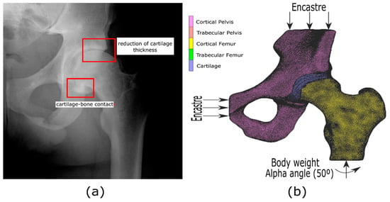
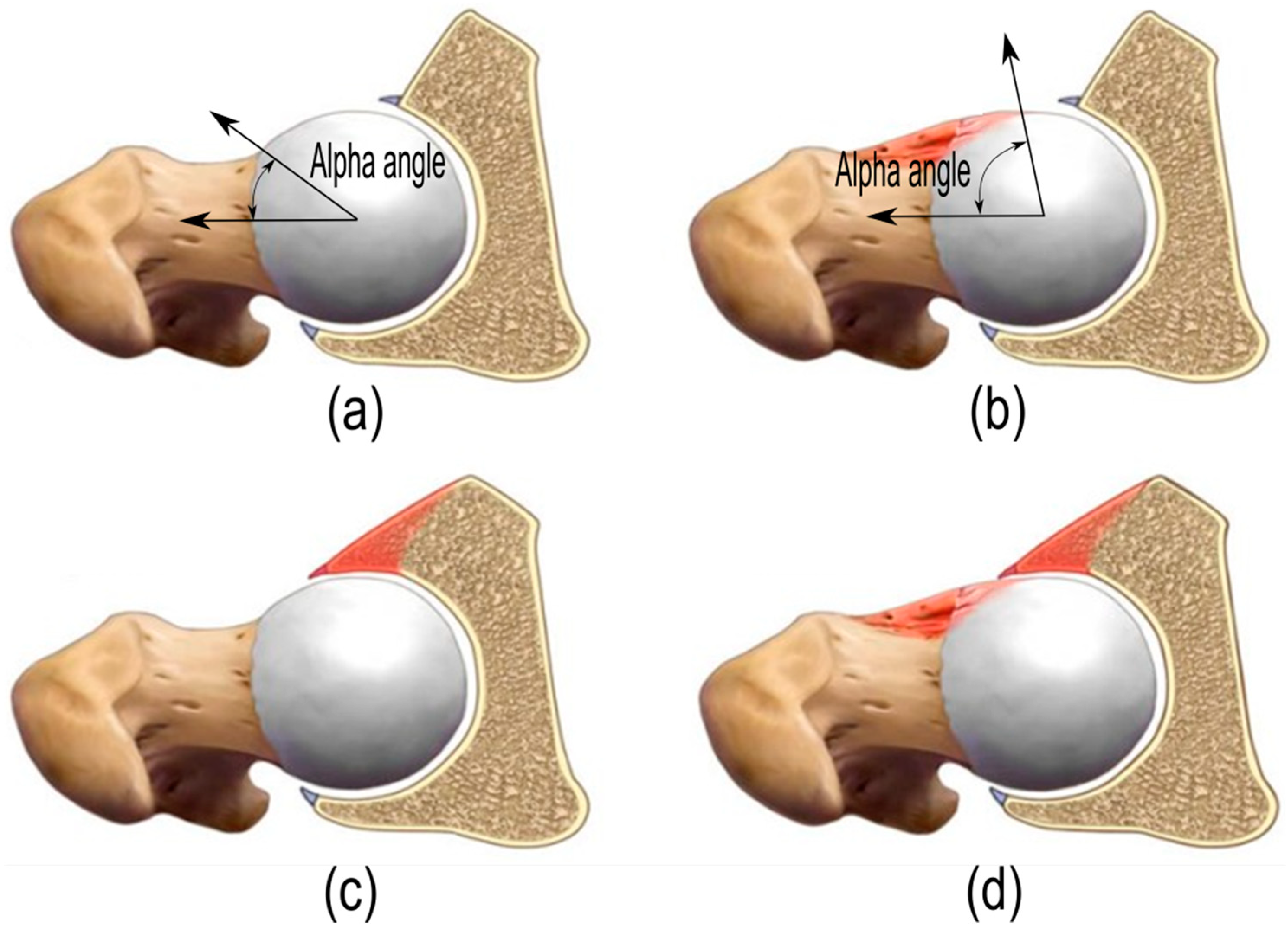
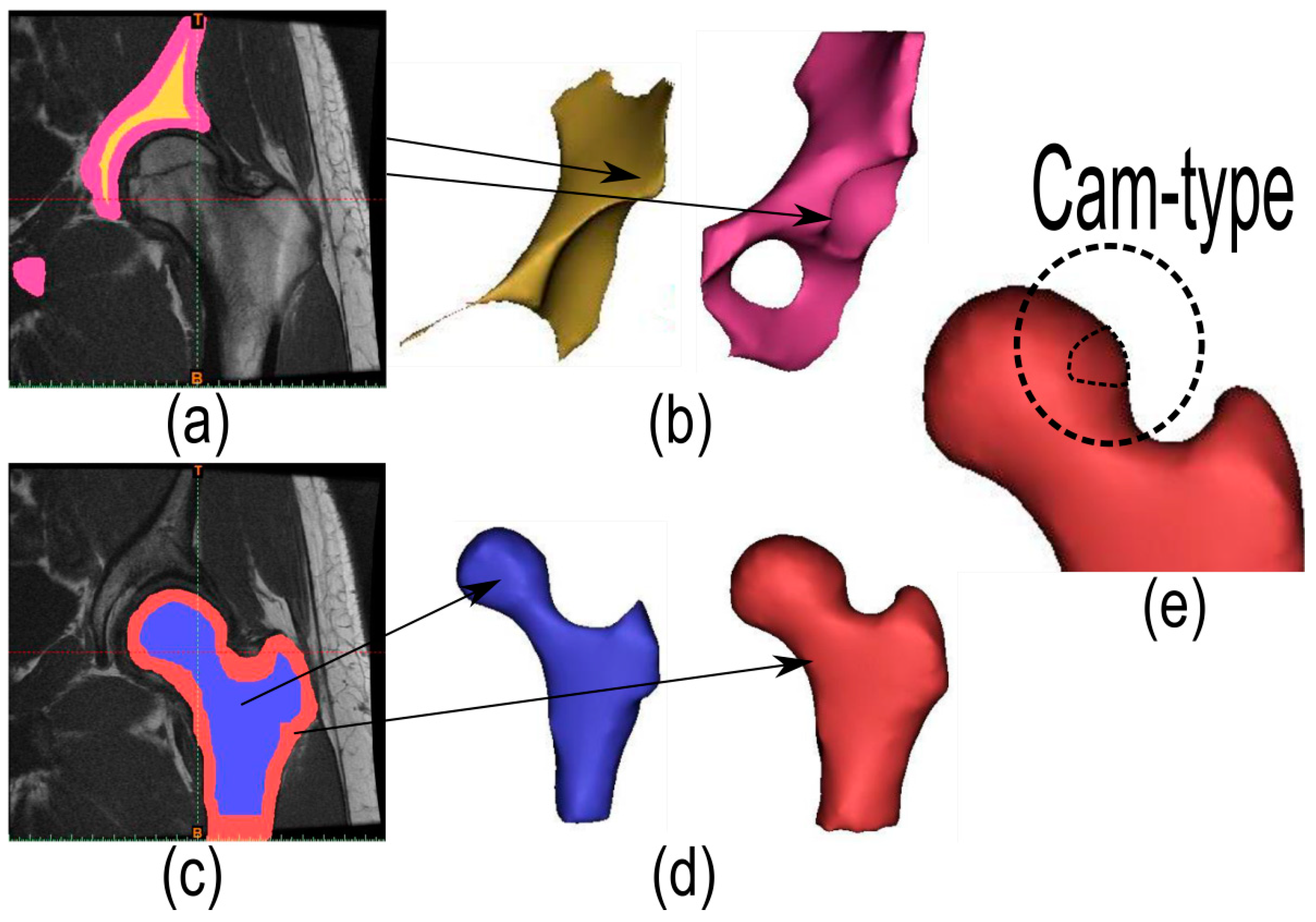
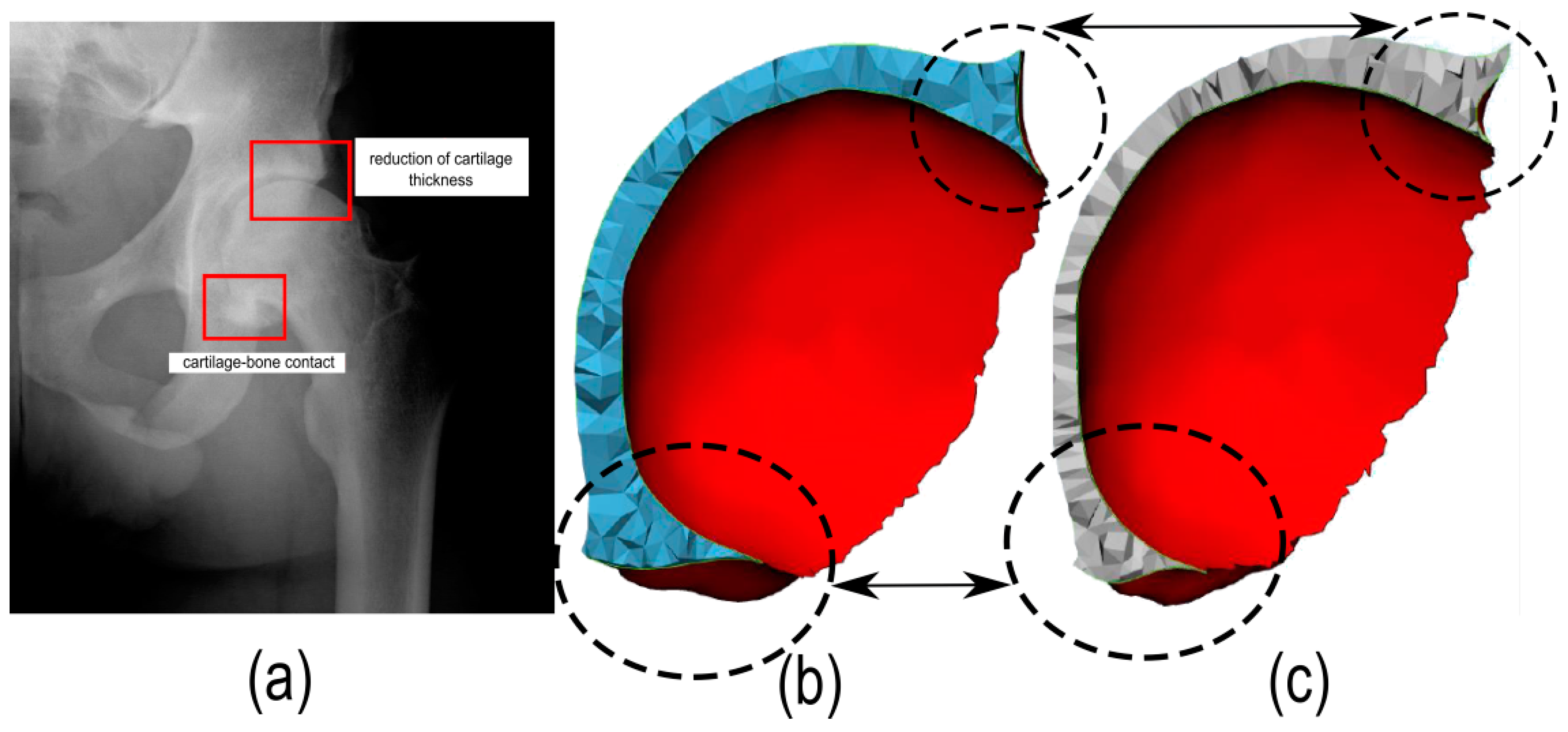
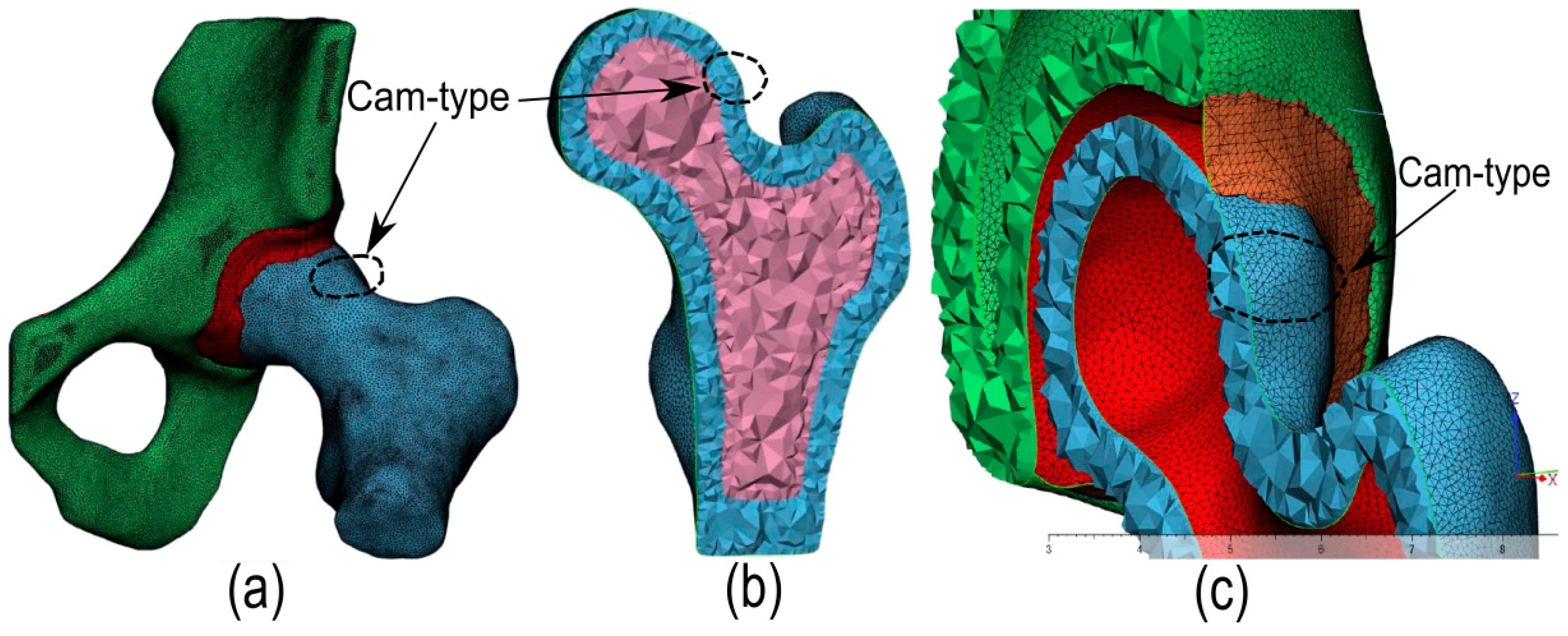
2. Femoroacetabular Impingement in Human Hip Joint

The morphologies that result in mechanical FAI can be Cam (an enlarged femoral head deformity), Pincer (an acetabular over-coverage), or a combination of both. These deformities, which appear as bumps, are characterized by a greater localized head radius. A variety of techniques have been used to quantify them. These include the alpha angle. Figure 1 shows the three types of FAI, in which the incongruity between the head of the femur and the acetabulum is visible [15,16]. Figure 1a shows the healthy hip joint, in which the alpha angle can be seen. The Cam-type deformity (Figure 1b) is identified by a decreased headneck offset. This leaves a pronounced anterolateral bump without a con-cavity at the femoral head and neck [17,18,19,20]. This has been ascribed to a number of factors. These include adverse hip trauma and loading [14,17,20], excessive athletic activity [14,21,22] and contact sports [23,24,25] before skeletal maturation. Persons who have a larger Cam deformity (i.e., greater alpha angle) [26], face a greater risk of anterosuperior femoral head obstruction with the acetabulum. This can occur during motions that combine hip flexion, rotation [9,20,21,27,28,29,30] and squatting [9,11,29,30,31]. The result can be early adult cartilage degeneration [3,15,28,32]. The early stages of FAI are seldom painful. Consequently, it may not be recognized during its preliminary asymptomatic settling-in phase [33,34,35,36]. However, early diagnosis of FAI and treatment are important to minimize the risk of severe irreversible damage to the hip cartilage, and osteoarthritis (OA). Pincer-type describes the condition in which the socket or acetabulum for the ball or femoral head is over-covered (Figure 1c). This over-coverage typically appears along the front-top rim of the socket (acetabulum). Pincers occur more frequently in women who are in in their 30s and 40s and are athletically active [18,37]. Finally, Figure 1d shows the FAI mixed-type [38,39].

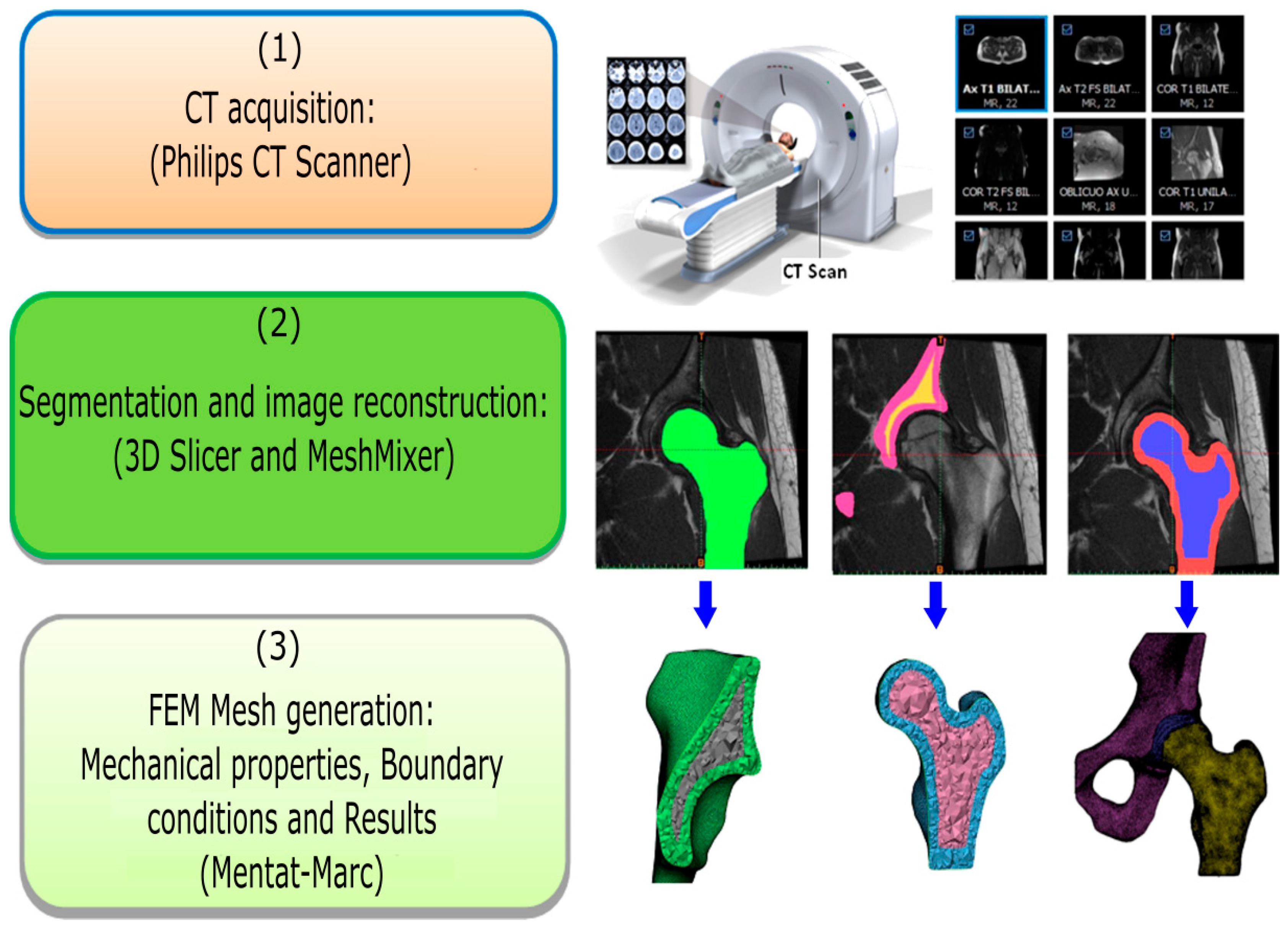
3. Materials and Methods

The methodology used to obtain the FE models and their subsequent numerical simulation appears below. It is based on the following steps: (1) CT scan acquisition, (2) segmentation and image reconstruction, and (3) FEM models. Figure 2 summarizes the steps followed to obtain the FE models from the patient’s CT scan.

3.1. CT Acquisition, Segmentation, and Image Reconstruction

FE models for biomechanical studies are usually constructed by means of patient-specific geometry (X-ray, Tomography, Computerized Axial Tomography (CT), Magnetic Resonance Imaging (MRI)), or by computer-aided design software [9,11,40,41,42,43,44]. Computerized Axial Tomography or CT scan is one of the tests that are commonly used for medical imaging diagnosis [45]. In the present case, two medical CT scans of the same patient (male, 80 kg in weight), obtained five years apart, were conducted. The older CT scan corresponds to the healthy hip joint when the patient was 22 years old, whereas the most recent CT scan corresponds to the hip joint with Cam-type femoroacetabular impingement (when the patient was 27 years old). In this case, a Philips CT Scanner was used to obtain the CT scans for both hip joints. Its configuration was: 512 × 512 matrix size, 168 mm window width, 0.32 mm pixel pitch, 5 mm cutoff pitch, 120 kVp, and 80 mA. Both medical CT scans provided DICOM files (.DCM) of the healthy and Cam-type femoroacetabular impingement patient’s hip joints. The segmentation process was conducted with the free 3D software Slicer [46]. To ensure that the cortical and cancellous bone were considered as independent parts of the hip and femur, the segmentation process was based on the threshold values of Hounsfield units (HU). Two different masks were created for the cortical and cancellous bone. A threshold with values that ranged from 700 Hu to 3070 Hu was used for the cortical bone mask. A threshold with a range of values from 150 HU to 700 HU was used for the trabecular bone and cartilage. Smoothing and repairing the defects of the segmentation process was conducted with free MeshMixer software. It generated both models in STL files format [47]. Figure 3 shows the segmentation process using the free 3D Slicer software and the smoothing and repairing of defects, generating the masks of the damaged hip joint using the MeshMixer software. Figure 3a shows the pelvic segmentation process, whereas Figure 3b shows the pelvic cancellous and cortical bone masks. The femur segmentation appears in Figure 3c, and Figure 3d shows the femur cancellous and cortical bone masks, in which, the Cam-type can be seen.
In addition, Figure 4a shows a radiograph of the patient at age 27 years. The reduction in the cartilage since the patient was 22 years of age is apparent. Furthermore, it can be seen that contact between the head of the femur and the acetabulum of the pelvis is imminent. It will cause a condition of arthrosis. Figure 4b shows, respectively, the masks obtained for the patient’s healthy cartilage and the masks for the damaged cartilage (Figure 4c, obtained recently with the Cam-type) in which a severe reduction in the thickness of the cartilage is visible, especially in the outer areas. This last figure indicates that the cartilage has been damaged and is smaller. Thus, less of the head of the femur is covered by cartilage.

3.2. Finite Element Models Proposed

After both STL files were generated (for the healthy and Cam-type hip joints), they were imported into the Marc Mentat® software [48] for the generation of the mesh of the cortical and cancellous bone and cartilage, and their subsequent FE analysis. The mesh for both hip joints FE models was created by 4-node tetrahedral elements with linear formulation. After each FE model was generated, an analysis of sensibility was conducted. The reason for this analysis was to determine the correct size of the elements used to ensure good results at the lowest computational cost. For all the FE models, element sizes of 0.32, 0.65, 1.0, 1.2, and 1.6 mm were used. A compression test was applied for each proposed FE model, with their different sizes of proposed elements. This test consisted of the application of a load of 40 kg in the longitudinal direction of the femur (not including its rotation of this bone). All the proposed FE models with all the different mesh sizes were simulated in computers with by Xeon processor, CPU 2.2 GHz (two processors) and 128.00 GB (random access memory (RAM)). The maximum values for the von Mises stresses from all the FE models and their computational cost were obtained, and appear in Table 1. The table indicates that, as the mesh size decreased, the computational cost increased, and the difference between the von Mises stresses between each mesh sizes analyzed was smaller. For example, the von Mises stresses obtained when the mesh size was 0.65 mm hardly differed from the stresses obtained for a mesh size of 0.32 mm (0.98 MPa vs. 0.96 MPa for healthy; and 2.28 MPa vs. 2.27 MPa for Cam-type), whereas the computational cost was notably greater (2184 min vs. 1718 min for healthy; and 2319 min vs. 1987 min for Cam-type). Once the results obtained were analyzed according to the von Mises stresses and the required computational cost, a mesh size of 0.65 mm was selected to carry out the study of a healthy and Cam-type hip joint considering an alpha angle of 50° and the patient’s body weight of 80 kg.
Figure 5 shows the mesh that was generated with the MeshMixer software after it was imported into the Mentat-Marc® software, considering a mesh size of 0.65 mm. Figure 5a shows the FE model with the damaged hip joint (of the Cam-type), whereas Figure 5b,c shows, respectively and in detail, the femur and the pelvis with the cartilage. In addition, Table 2 summarizes the number of elements and nodes of the pelvis, femur, and cartilage of the healthy and Cam-type hip joints when the mesh size considered is 0.65 mm.

3.2.1. Mechanical Properties and Material Behavior

As described in the introduction, several authors have considered both linear and non-linear behavior for the study of Cam-type hip joints by means of the FEM. For example, in [9] an isotropic and linear elastic FE model of the bone and cartilage was considered. In this case, the Young’s modulus (E) and Poisson’s ratio (ν) considered for the cartilage were 12 MPa and 0.45 MPa respectively. However, for the cortical and cancellous bone, the values were 20 MPa and 100 MPa respectively. In [10], the cartilage was also modeled as a linear elastic material with E = 12 MPa and ν = 0.45. In this study, both the cortical and cancellous bone of the hip and femur were considered to be rigid elements. In a very similar way, other authors [12] considered the behavior of cartilage as linear elastic and isotropic behavior with E = 12 MPa and ν = 0.4, whereas the bony components were assumed to be rigid. Other authors [49] have concentrated on the Cam-type hip joint. In doing so, they have taken into account the age of the patient and assumed an isotropic behavior and linear elastic material properties for the cortical and trabecular bones. For example, for an age range of 30 to 35 years, the authors considered E = 1 GPa for the cancellous bone and 17 GPa for the cortical bone. The Poisson’s ratio was 0.4 for both. For older patients (of 70 to 79 years of age) the authors considered E = 1 GPa for the cancellous bone and 15.4 GPa for the cortical bone, with a Poisson’s ratio of 0.4 for both. In a similar way to [9], other authors [50] have considered cartilage to be isotropic and linear elastic with a Young’s modulus of 12 MPa and Poisson’s ratio of 0.42 and 0.495 (for linear elastic and neo-Hookean behavior). The cortical and trabecular bones for the femur and hip were modeled as rigid. On the other hand, some authors have considered non-isotropic and non-linear FE models for the bone and cartilage. For example [31,51] considered an orthotropic behavior for the bones and isotropic for the cartilage. They assumed that E1 = 11.6 GPa, E2 = 12.2 GPa, E3 = 19.9 GPa, shear moduli G12 = 4.0 GPa, G13 = 5.0 GPa, G23 = 5.4 GPa and Poisson’s ratio ν12 = 0.42 and ν13 = ν23 = 0.23 for the femur and hip. However, for cartilage E = 12 MPa and ν = 0.4. Other authors [14] considered the material properties of bones to be based on empirical formula and subject to subject specific bone material properties using the Hounsfield units. The elastic modulus considered for the cortical bone was calculated according to E = 12,900.ρ (MPa), where ρ was the bone density, the Poisson’s ratio was assumed to be 0.3 and the cartilage was modeled with a constant Young’s modulus of 6 MPa and with a Poisson’s ratio of 0.49. More recently [52], the authors assumed an elastoplastic and isotropic behavior for the bones (E = 17,000 MPa and ν = 0.3 for the cortical bone; E = 150 MPa and ν = 0.3 for the cancellous bone) and linear elasticity for the cartilage (E = 12 MPa and ν = 0.4).
In the current paper, and according to the considerations made by the aforementioned authors, an isotropic and linear elastic behavior of the bone and cartilage was considered. For the cortical and trabecular bone, 17,000 MPa and 150 MPa were assumed for the Young’s modulus, whereas the Poisson ratio was 0.3 for both. Finally, it was assumed that E = 12 MPa and ν = 0.4 for the cartilage.

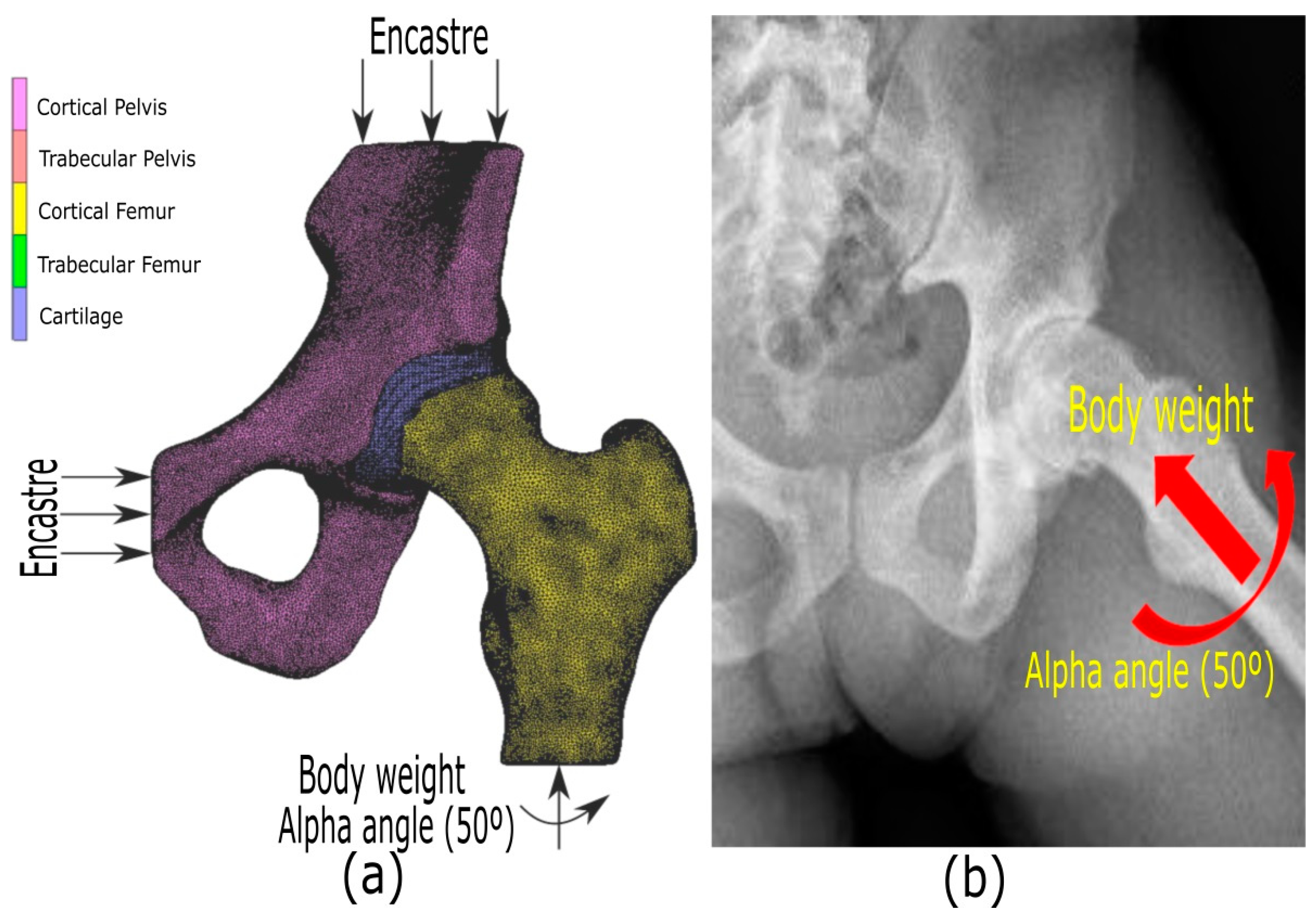
3.2.2. Boundary Conditions for the Proposed FE Models

The proposed boundary conditions for both healthy and Cam-type hip joints were an encastre condition on the pelvis (in the area away from the cartilage to be studied), and a vertical load of 80 kg (the patient’s body weight) that is combined with an alpha angle of 50° (counterclockwise) of the femur. This rotation of 50° must ensure that, for the Cam-type joint studied, the malformation in the head of the femur will come into contact with the inside of the cartilage, thereby causing an overload on the latter. Both loads (80 kg and 50°) were applied as follows on the proposed FEM models: first, a local polar coordinate system that was centered on the head of the femur was defined. The objective was simply to orient the nodes to where the vertical load of 80 kg and the alpha angle of 50° was to be applied according to this polar system. Next, the femur was rotated at an alpha angle of 50° in the counterclockwise direction (to the raised angular axis). Once this angle was rotated and the position of the rotated femur was maintained, the load of 80 kg was applied in the longitudinal direction of the femur (according to the raised radial axis). Similarly, a mechanical contact between the head of the femur and the cartilage of the sliding type was considered. It permitted the mobility of the femur with respect to the remaining joints. For both of the proposed FE models, the contact considered was the “Stick-Slip” type, with a frictional coefficient of 0.01 [52]. Figure 6 shows the proposed FE models in which the applied boundary conditions appear (Figure 6a). Figure 6 also includes a radiograph of the patient’s hip joint. It shows that, for an alpha angle of 50° combined with the body weight, the irregularity of the Cam-type in the femur head could make contact with the cartilage (Figure 6b).

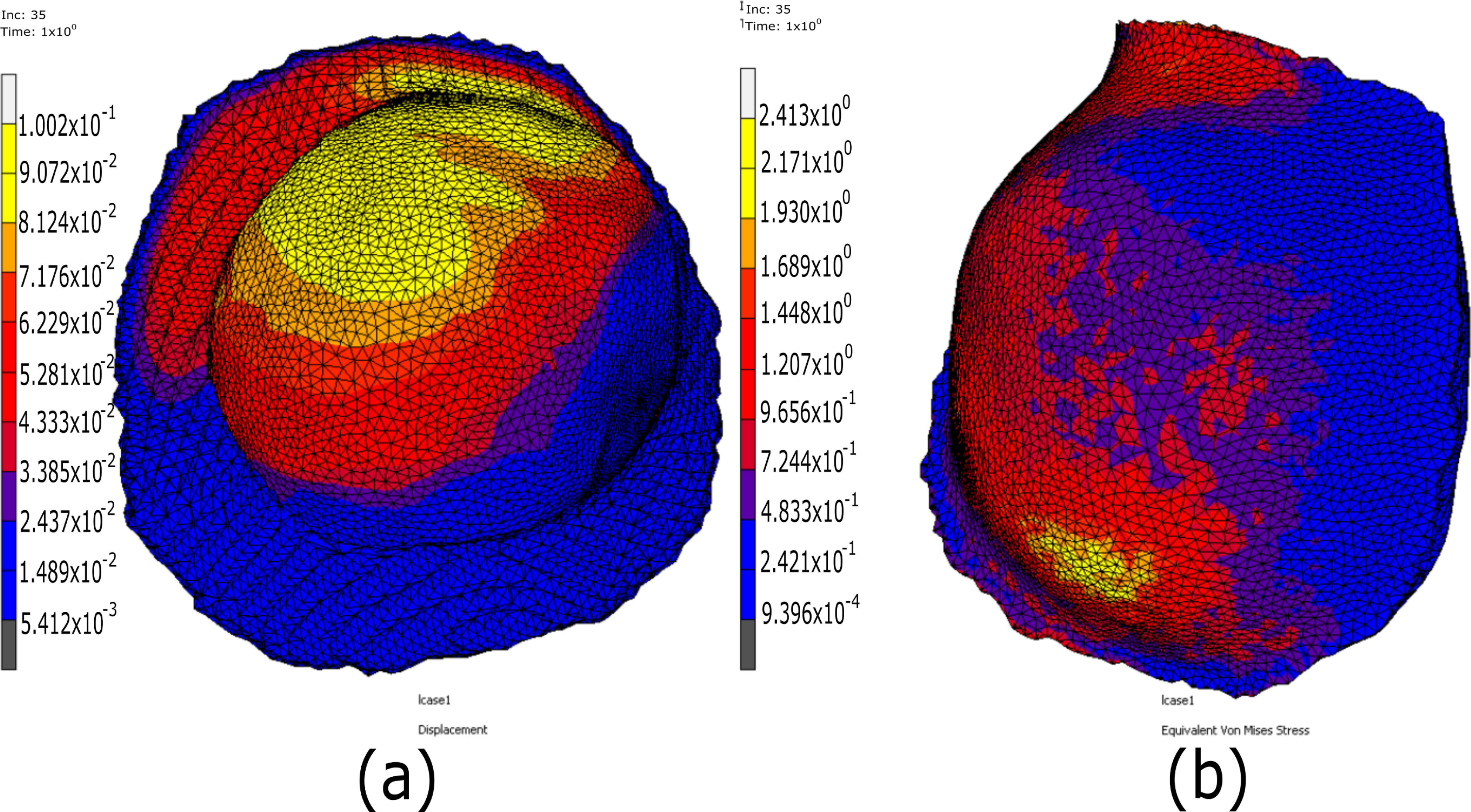
4. Results and Discussion

Figure 7, Figure 8 and Figure 9 show the results for the healthy and Cam-type femoroacetabular impingement hip joints FE models with a vertical load of 80 kg combined with an alpha angle of 50°. Figure 7a,b shows, respectively, the maximum displacement and the von Mises stresses in the cartilage of the healthy hip joint FE model. It can be seen that the displacement and the von Mises stresses were, respectively, 0.1 mm and 2.41 MPa. In addition, Figure 8a,b shows, respectively, the maximum displacement and the von Mises stress on the cartilage of the Cam-type hip joint FE model. The results indicate that the maximum displacement of the cartilage was 0.437 mm, whereas the maximum von Mises stress was 6.9 MPa. The latter occurred on the anterosuperior bone surface, beneath the acetabular cartilage. This difference in the displacements experienced by the two FE models suggests that damaged cartilage undergoes a greater displacement of cartilage mass than healthy cartilage, which can produce direct contact between the femur bone and the pelvic bone. The damage that this type of pathology can cause over time can be significant. It can even result in direct contact between the head of the femur and the acetabulum of the pelvis, causing the patient to develop arthrosis. As has been observed, the malformation of the femur head (Cam-type) is the main cause of the increase in displacement and stresses on the cartilage. In normal conditions of the femur, this pathology should not occur.
Figure 9a,b shows, respectively, the contact pressure distribution on the acetabular cartilages of both the healthy and the Cam-type femoroacetabular impingement hip joint. These figures show peaks of contact pressures in the superior region of the cartilage with values of 2.24 MPa and 9.65 MPa, respectively. for the healthy and the damaged cartilage. This difference in the localized contact pressures in the superior region of the cartilage is largely due to the fact that the head of the femur is not fully covered by the cartilage (femoral head coverage).
The values of the stresses and contact pressures of the damaged FE model when the pathology is of the Cam-type are very similar to those that other researchers obtained when the applied load and alpha angle were similar to those in this paper (6.9 MPa). In [9], the authors obtained slightly higher von Mises stress values while patients were sitting and walking at 9.70 and 27.20 MPa, respectively. In the same way, the contact pressures obtained by the same researchers were also very similar to those obtained in the current work. The contact pressure peaks obtained by these researchers for the walking condition, with an alpha angle of 50° and a femoral head coverage angle of 0° (totally damaged cartilage) or 30° (undamaged cartilage), were 9.92 MPa and 3.55 MPa when walking. These are similar to the values obtained in this paper (9.65 MPa and 2.24 MPa MPa).
Other authors [11] obtained von Mises stress values that were more in line with the results obtained in the current work, with 15.2 ± 1.8 MPa while squatting for patients with the severe Cam type. For healthy patients, the stresses were 4.5 ± 0.1 MPa. In this case, the maximum stress occurred on the surface of the anterosuperior bone, below the acetabular cartilage. Some authors [12] obtained an elevated peak of von Mises stress in the anterosuperior cartilage 14.4 MPa and labrum 14.7 MPa, during hip flexion. During partial and full internal rotation, the von Mises stress was 28.2 MPa. These same authors obtained values for the contact pressure on the femoral cartilage of 8.6 MPa with an alpha angle of 32°, but when the alpha angle was 90°, the contact pressure reached values of 13.3 MPa. As a general rule, it can be stated that, in all of the work analyzed, cartilage stresses were higher for damaged cartilage than for healthy cartilage. Similarly, in all the cases analyzed, the damaged cartilage became thinner while the maximum stresses occurred on the anterosuperior bone surface, beneath the acetabular cartilage. In both the FE models that were studied in the current work, it was observed that the accumulated damage of the oldest cartilage was the greatest. This cartilage exhibited a notable reduction in the thickness of its outer areas. Our findings agree with clinical observations. They indicate that the area of damage and high von Mises stress and contact pressures are related. Further, the area of delamination of the cartilage for a femoroacetabular impingement of the Cam type and the data that our FE simulations produced are consistent with the loads that included a 50° alpha angle and the patient’s body weight (Figure 6). Cartilage damage in early hip osteoarthritis is the result of dysplasia or impingement and may require surgery. Surgery is usually undertaken to preserve the hip before severe osteoarthritis becomes evident and a resection or reorientation osteotomy [9,16] is necessary. This usually restores the joint’s geometry to normal. As a result, impingement or addressing dysplasia is prevented. Furthermore, the range of motion without pain is increased. There is only limited clinical information about the acetabulum’s normal shape, or the alpha angle and the coverage angle of the femoral head coverage. Our data show that, for daily walking activities, in which the load applied to the cartilage can be one’s own weight and the rotation of the femoral head (which can be around 50°), the stresses and contact pressures reach very high values for both healthy and damaged cartilage. This is due to Cam-type femoroacetabular impingement. These contact stresses and pressures, when acting on healthy cartilage for a period of five years, caused substantial damage. These results could be used to prevent cartilage degradation in young patients by limiting their mobility and not overloading their cartilage with rotations that approach 50°, along with a load on one leg of one’s entire body weight, in cases where the patient has not undergone surgical interventions such as resection or reorientation osteotomy, in view of the limitations of the FE proposed models. These FE models help to increase our understanding of joint degeneration etiology and the relationship between stress, displacement, and contact pressures on the cartilage; we should ensure that our assumptions simplify our work. Although cartilage is highly structured, biphasic anisotropic material, accounting for these aspects and also the tribological aspects of joint degeneration of how would be the increase our understanding of load sharing between the solid phase and interstitial synovial fluid in cartilage. In future work, it would be advisable to update the mechanical behavior of both cartilage and bone, and to examine models that consider non-linearities for both. Our work concentrated only on one study patient (a healthy young man), which limited the findings of our study. Consequently, it would be of great interest to conduct a much larger study that considers older age ranges, and even a consideration of sex.

5. Conclusions

Cam-type femoroacetabular impingement (FAI) is a serious problem. It restricts mobility and greatly reduces the quality of life of patients who suffers from it. The objective of this work has been to analyze and compare the increase in the von Mises stress distribution and displacement of the cartilage of healthy and damaged human hip joints with Cam-type using the FEM. The FE models of both hip joints were obtained in an interval of five years, using medical CT scans in both cases to obtain the DICOM files first. Next, a segmentation process was conducted using the free Slicer software. Based on the thresh-old values of Hounsfield units (HU), masks corresponding to the cortical and spongy bone of the femur and pelvis, as well as the cartilage, were generated. The smoothing and repairing these masks was accomplished using the free MeshMixer software, generating both models in the STL file format. Finally, the Marc Mentat software imported these STL models, in which the FE simulations were conducted, to obtain the displacements and von Mises stresses on the cartilage for both hip joints. The results of the FE analysis showed that the displacement and the von Mises stress obtained in the cartilage of the healthy hip joint were 0.1 mm and 2.41 MPa, respectively. For the cartilage of the Cam-type hip joint, they were 0.437 mm. and 6.9 MPa. This increase in displacement and stress experienced by the cartilage of the Cam-type hip joint, as well as the reduction in thickness of this cartilage, suggests that there is mechanical contact between the head of the femur and the acetabulum of the pelvis. This will certainly result in a condition of osteoarthritis for the patient in future years.

Author Contributions

Conceptualization, R.L.L., F.S.G. and M.C.B.; methodology, R.L.L., F.S.G. and S.Í.M.; software, R.L.L., F.S.G. and S.Í.M.; formal analysis, Á.P.S., I.M.L. and R.P.C.; investigation, R.L.L., F.S.G. and M.C.B.; resources, A.R.S.M., E.F.M. and M.R.S.; data curation, Á.P.S., I.M.L. and R.P.C.; writing—original draft preparation, M.C.B., S.Í.M., A.R.S.M., E.F.M. and M.R.S.; writing—review and editing, Á.P.S., I.M.L. and R.P.C.; supervision, R.L.L. and F.S.G. All authors have read and agreed to the published version of the manuscript.

Funding

This work was supported for publication by the “Conselleria de Innovación, Universidades, Ciencia y Sociedad Digital” of the Generalitat Valenciana through the GVA 2021 project. The authors would like to thank also to the INGEGRAF association.

Institutional Review Board Statement

The study was conducted according to the guidelines of the Declaration of Helsinki, and approved by the Ethics Committee of the University of La Rioja.

Informed Consent Statement

Informed consent was obtained from all subjects involved in the study.

Acknowledgments

The authors would like to thank the anonymous reviewers for their insightful, relevant and valuable comments.

Conflicts of Interest

The authors declare no conflict of interest.

References

  1. Navarro-Zarza, J.E.; Villaseñor-Ovies, P.; Vargas, A.; Canoso, J.J.; Chiapas-Gasca, K.; Hernández-Díaz, C.; Saavedra, M.Á.; Kalish, R.A. Clinical anatomy of the pelvis and hip. Reumatol. Clin. 2012, 8, 33–38. [Google Scholar] [CrossRef] [PubMed]
  2. Bogunovic, L.; Nho, S.J. Femoroacetabular impingement. In Orthopaedic Knowledge Update: Sports Medicine; Wolters Kluwer Health: Philadelphia, PA, USA, 2018; Volume 5, pp. 127–140. [Google Scholar]
  3. Beck, M.; Kalhor, M.; Leunig, M.; Ganz, R. Hip morphology influences the pattern of damage to the acetabular cartilage. Femoroacetabular impingement as a cause of early osteoarthritis of the hip. J. Bone Jt. Surg. 2005, 87, 1012–1018. [Google Scholar] [CrossRef] [PubMed] [Green Version]
  4. Bedi, A.; Kelly, B.T. Femoroacetabular impingement. JBJS 2013, 95, 82–92. [Google Scholar] [CrossRef] [Green Version]
  5. Lavigne, M.; Parvizi, J.; Beck, M.; Siebenrock, K.A.; Ganz, R.; Leunig, M. Anterior femoroacetabular impingement: Part I. Techniques of joint preserving surgery. Clin. Orthop. Relat. Res. 2004, 418, 61–66. [Google Scholar] [CrossRef]
  6. Konan, S.; Rayan, F.; Haddad, F.S. Is the frog lateral plain radiograph a reliable predictor of the alpha angle in femoroacetabular impingement? J. Bone Jt. Surg. 2010, 92, 47–50. [Google Scholar] [CrossRef]
  7. Eijer, H.; Leunig, M.; Mahomed, M.N.; Ganz, R. Cross-table lateral radiographs for screening of anterior femoral head-neck Offset in patients with femoro-acetabular impingement. HIP Int. 2001, 11, 37–41. [Google Scholar] [CrossRef]
  8. Ng, K.G.; Lamontagne, M.; Labrosse, M.R.; Beaulé, P.E. Hip joint stresses due to cam-type femoroacetabular impingement: A systematic review of finite element simulations. PLoS ONE 2016, 11, e0147813. [Google Scholar] [CrossRef] [PubMed]
  9. Chegini, S.; Beck, M.; Ferguson, S.J. The effects of impingement and dysplasia on stress distributions in the hip joint during sitting and walking: A finite element analysis. J. Orthop. Res. 2009, 27, 195–201. [Google Scholar] [CrossRef]
  10. Arbabi, E.; Chegini, S.; Boulic, R.; Tannast, M.; Ferguson, S.J.; Thalmann, D. Penetration depth method—Novel real-time strategy for evaluating femoroacetabular impingement. J. Orthop. Res. 2010, 28, 880–886. [Google Scholar] [CrossRef]
  11. Ng, K.G.; Rouhi, G.; Lamontagne, M.; Beaulé, P.E. Finite element analysis examining the effects of cam FAI on hip joint mechanical loading using subject-specific geometries during standing and maximum squat. HSS J. 2012, 8, 206–212. [Google Scholar] [CrossRef] [Green Version]
  12. Jorge, J.P.; Simões, F.M.F.; Pires, E.B.; Rego, P.A.; Tavares, D.G.; Lopes, D.S.; Gaspar, A. Finite element simulations of a hip joint with femoroacetabular impingement. Comput. Methods Biomech. Biomed. Eng. 2014, 17, 1275–1284. [Google Scholar] [CrossRef] [PubMed]
  13. Hellwig, F.L.; Tong, J.; Hussell, J.G. Hip joint degeneration due to cam impingement: A finite element analysis. Comput. Methods Biomech. Biomed. Eng. 2016, 19, 41–48. [Google Scholar] [CrossRef] [PubMed]
  14. Roels, P.; Agricola, R.; Oei, E.H.; Weinans, H.; Campoli, G.; Zadpoor, A. Mechanical factors explain development of cam-type deformity. Osteoarthr. Cartil. 2014, 22, 2074–2082. [Google Scholar] [CrossRef] [Green Version]
  15. Ganz, R.; Parvizi, J.; Beck, M.; Leunig, M.; Nötzli, H.; Siebenrock, K.A. Femoroacetabular impingement: A cause for osteoarthritis of the hip. Clin. Orthop. Relat. Res. 2003, 417, 112–120. [Google Scholar]
  16. Beck, M.; Leunig, M.; Parvizi, J.; Boutier, V.; Wyss, D.; Ganz, R. Anterior femoroacetabular impingement: Part II. Midterm results of surgical treatment. Clin. Orthop. Relat. Res. 2004, 418, 67–73. [Google Scholar] [CrossRef]
  17. Kim, K.C.; Hwang, D.S.; Lee, C.H.; Kwon, S.T. Influence of femoroacetabular impingement on results of hip arthroscopy in patients with early osteoarthritis. Clin. Orthop. Relat. Res. 2007, 456, 128–132. [Google Scholar] [CrossRef]
  18. Tannast, M.; Siebenrock, K.A.; Anderson, S.E. Femoroacetabular impingement: Radiographic diagnosis—What the radiologist should know. AJR Am. J. Roentgenol. 2007, 188, 1540–1552. [Google Scholar] [CrossRef] [Green Version]
  19. Ito, K.; Minka-II, M.A.; Leunig, M.; Werlen, S.; Ganz, R. Femoroacetabular impingement and the cam-effect: A MRI-based quantitative anatomical study of the femoral head-neck offset. J. Bone Jt. Surg. 2001, 83, 171–176. [Google Scholar] [CrossRef]
  20. Siebenrock, K.A.; Wahab, K.A.; Werlen, S.; Kalhor, M.; Leunig, M.; Ganz, R. Abnormal extension of the femoral head epiphysis as a cause of cam impingement. Clin. Orthop. Relat. Res. 2004, 418, 54–60. [Google Scholar] [CrossRef]
  21. Agricola, R.; Heijboer, M.P.; Ginai, A.Z.; Roels, P.; Zadpoor, A.A.; Verhaar, J.A.; Weinans, H.; Waarsing, J.H. A cam deformity is gradually acquired during skeletal maturation in adolescent and young male soccer players: A prospective study with minimum 2-year follow-up. Am. J. Sports Med. 2014, 42, 798–806. [Google Scholar] [CrossRef]
  22. Philippon, M.; Schenker, M.; Briggs, K.; Kuppersmith, D. Femoroacetabular impingement in 45 professional athletes: Associated pathologies and return to sport following arthroscopic decompression. Knee Surg. Sports Traumatol. Arthrosc. 2007, 15, 908–914. [Google Scholar] [CrossRef] [Green Version]
  23. Laude, F.; Boyer, T.; Nogier, A. Anterior femoroacetabular impingement. Jt. Bone Spine 2007, 74, 127–132. [Google Scholar] [CrossRef]
  24. Myers, S.R.; Eijer, H.; Ganz, R. Anterior femoroacetabular impingement after periacetabular osteotomy. Clin. Orthop. Relat. Res. 1999, 363, 93–99. [Google Scholar] [CrossRef]
  25. Amanatullah, D.F.; Antkowiak, T.; Pillay, K.; Patel, J.; Refaat, M.; Toupadakis, C.A.; Jamali, A.A. Femoroacetabular impingement: Current concepts in diagnosis and treatment. Orthopedics 2015, 38, 185–199. [Google Scholar] [CrossRef] [PubMed]
  26. Nötzli, H.P.; Wyss, T.F.; Stoecklin, C.H.; Schmid, M.R.; Treiber, K.; Hodler, J. The contour of the femoral head-neck junction as a predictor for the risk of anterior impingement. J. Bone Jt. Surg. 2002, 84, 556–560. [Google Scholar] [CrossRef]
  27. Kapron, A.L.; Anderson, A.E.; Aoki, S.K.; Phillips, L.G.; Petron, D.J.; Toth, R.; Peters, C.L. Radiographic prevalence of femoroacetabular impingement in collegiate football players: AAOS Exhibit Selection. JBJS 2011, 93, e111. [Google Scholar] [CrossRef]
  28. Heijboer, M.P.; Bierma-Zeinstra, S.M.; Verhaar, J.A.; Weinans, H.; Waarsing, J.H. Cam impingement causes osteoarthritis of the hip: A nationwide prospective cohort study (CHECK). Ann. Rheum. Dis. 2013, 72, 918–923. [Google Scholar]
  29. Lamontagne, M.; Brisson, N.; Kennedy, M.J.; Beaulé, P.E. Preoperative and postoperative lower-extremity joint and pelvic kinematics during maximal squatting of patients with cam femoro-acetabular impingement. JBJS 2011, 93 (Suppl. 2), 40–45. [Google Scholar] [CrossRef]
  30. Lamontagne, M.; Kennedy, M.J.; Beaulé, P.E. The effect of cam FAI on hip and pelvic motion during maximum squat. Clin. Orthop. Relat. Res. 2009, 467, 645–650. [Google Scholar] [CrossRef] [Green Version]
  31. Ng, K.G.; Lamontagne, M.; Adamczyk, A.P.; Rahkra, K.S.; Beaulé, P.E. Patient-specific anatomical and functional parameters provide new insights into the pathomechanism of cam FAI. Clin. Orthop. Relat. Res. 2015, 473, 1289–1296. [Google Scholar] [CrossRef] [Green Version]
  32. Speirs, A.D.; Beaulé, P.E.; Rakhra, K.S.; Schweitzer, M.E.; Frei, H. Increased acetabular subchondral bone density is associated with cam-type femoroacetabular impingement. Osteoarthr. Cartil. 2013, 21, 551–558. [Google Scholar] [CrossRef] [PubMed] [Green Version]
  33. Jaberi, F.M.; Parvizi, J. Hip pain in young adults: Femoroacetabular impingement. J. Arthroplast. 2007, 22, 37–42. [Google Scholar] [CrossRef] [PubMed]
  34. Standaert, C.J.; Herring, S.A. Expert opinion and controversies in musculoskeletal and sports medicine: Stingers. Arch. Phys. Med. Rehabil. 2009, 90, 402–406. [Google Scholar] [CrossRef]
  35. Ergen, F.B.; Vudalı, S.; Şanverdi, E.; Dolgun, A.; Aydıngöz, Ü. CT assessment of asymptomatic hip joints for the background of femoroacetabular impingement morphology. Diagn. Interv. Radiol. 2014, 20, 271. [Google Scholar] [CrossRef] [PubMed]
  36. Jung, K.; Restrepo, C.; Hellman, M.; AbdelSalam, H.; Morrison, W.; Parvizi, J. The prevalence of cam-type femoroacetabular deformity in asymptomatic adults. J. Bone Jt. Surg. 2011, 93, 1303–1307. [Google Scholar] [CrossRef] [Green Version]
  37. Camacho-Alvarez, D.; Mardones-Peterman, R. Femoroacetabular impingement: Association between the overcoverage and acetabular cartilage delamination areas. Rev. Esp. Cir. Ortop. Traumatol. Engl. Ed. 2013, 57, 111–116. [Google Scholar] [CrossRef]
  38. Souza, B.G.S.; Cardoso, R.M.; Loque, R.S.; Monte, L.F.R.; Sabino, J.P.; de Oliveira, V.M. Mixed-type femoroacetabular impingement associated with subspine impingement: Recognizing the trifocal femoropelvic impingement. Rev. Bras. Ortop. Engl. Ed. 2018, 53, 389–394. [Google Scholar] [CrossRef]
  39. İnan, U.; Harmanşa, S.; Ömeroğlu, H. Treatment of mixed type femoroacetabular impingement using safe surgical hip dislocation in adults. Jt. Dis. Relat. Surg. 2016, 27, 160–166. [Google Scholar] [CrossRef]
  40. Cavas, F.; Piñero, D.; Velázquez, J.S.; Mira, J.; Alió, J.L. Relationship between corneal morphogeometrical properties and biomechanical parameters derived from dynamic bidirectional air applanation measurement procedure in keratoconus. Diagnostics 2020, 10, 640. [Google Scholar] [CrossRef]
  41. Velázquez, J.S.; Cavas, F.; Piñero, D.P.; Cañavate, F.J.; Del Barrio, J.A.; Alio, J.L. Morphogeometric analysis for characterization of keratoconus considering the spatial localization and projection of apex and minimum corneal thickness point. J. Adv. Res. 2020, 24, 261–271. [Google Scholar] [CrossRef] [PubMed]
  42. Alifa, R.; Piñero, D.; Velázquez, J.; Alió del Barrio, J.L.; Cavas, F.; Alió, J.L. Changes in the 3D corneal structure and morphogeometric properties in keratoconus after corneal collagen crosslinking. Diagnostics 2020, 10, 397. [Google Scholar] [CrossRef]
  43. Toprak, I.; Cavas, F.; Vega, A.; Velázquez, J.S.; Alio del Barrio, J.L.; Alio, J.L. Evidence of a down syndrome keratopathy: A three-dimensional (3-D) morphogeometric and volumetric analysis. J. Pers. Med. 2021, 11, 82. [Google Scholar] [CrossRef]
  44. Toprak, I.; Cavas, F.; Velázquez, J.S.; Del Barrio, J.L.A.; Alió, J.L. Three-dimensional morphogeometric and volumetric characterization of cornea in pediatric patients with early keratoconus. Am. J. Ophthalmol. 2021, 222, 102–111. [Google Scholar] [CrossRef]
  45. Goerne, H.; Rajiah, P. Computed tomography. In Right Heart Pathology: From Mechanism to Management; Springer International Publishing: Cham, Switzerland, 2018; pp. 601–612. [Google Scholar]
  46. Fedorov, A.; Beichel, R.; Kalpathy-Cramer, J.; Finet, J.; Fillion-Robin, J.-C.; Pujol, S.; Bauer, C.; Jennings, D.; Fennessy, F.; Sonka, M.; et al. 3D Slicer as an image computing platform for the Quantitative Imaging Network. Magn. Reson. Imaging 2012, 30, 1323–1341. [Google Scholar] [CrossRef] [PubMed] [Green Version]
  47. Autodesk Meshmixer. Available online: http://www.meshmixer.com/ (accessed on 7 May 2019).
  48. MSC Mentat Marc [Software]; MSC Software Corporation: Newport Beach, CA, USA, 2014.
  49. Rothenfluh, E.; Zingg, P.; Dora, C.; Snedeker, J.G.; Favre, P. Influence of resection geometry on fracture risk in the treatment of femoroacetabular impingement: A finite element study. Am. J. Sports Med. 2021, 40, 2002–2008. [Google Scholar] [CrossRef] [PubMed]
  50. Liechti, E.F.; Ferguson, S.J.; Tannast, M. Protrusio acetabuli: Joint loading with severe pincer impingement and its theoretical implications for surgical therapy. J. Orthop. Res. 2015, 33, 106–113. [Google Scholar] [CrossRef] [Green Version]
  51. Ng, K.G.; Mantovani, G.; Lamontagne, M.; Labrosse, M.R.; Beaulé, P.E. Cam FAI and smaller neck angles increase subchondral bone stresses during squatting: A finite element analysis. Clin. Orthop. Relat. Res. 2019, 477, 1053. [Google Scholar] [CrossRef] [PubMed]
  52. Alonso-Rasgado, T.; Jimenez-Cruz, D.; Bailey, C.G.; Mandal, P.; Board, T. Changes in the stress in the femoral head neck junction after osteochondroplasty for hip impingement: A finite element study. J. Orthop. Res. 2012, 30, 1999–2006. [Google Scholar] [CrossRef] [PubMed]
Figure 1. Types of hip joint with femoroacetabular impingement: (a) healthy hip joint, (b) Cam-type, (c) Pincer-type and (d) mixed-type [7,25].
Applsci 11 11101 g001
Figure 2. Steps followed to obtain the FE models from the patient’s CT scan.
Applsci 11 11101 g002
Figure 3. Segmentation process and generation of the masks: (a) pelvic segmentation, (b) pelvic cancellous and cortical bone masks, (c) femur segmentation and (d) femur cancellous and cortical bone masks (with Cam-type), (e) detail of the cam-type on the head of the femur.
Applsci 11 11101 g003
Figure 4. Reduction of the cartilage: (a) radiograph of the patient at age 27, (b) masks obtained for the patient’s healthy cartilage and (c) masks obtained for the patient’s damaged cartilage.
Applsci 11 11101 g004
Figure 5. Mesh imported into the Mentat-Marc® software: (a) FE model with hip joint damaged (with CAM), (b) details of the femur and (c) details of the pelvis and cartilage.
Applsci 11 11101 g005
Figure 6. (a) Proposed Cam-type FE model with the applied boundary conditions and (b) radiograph of the patient´s hip joint including a displacement and rotation of 50° of the femur in the Cam-type hip joints.
Applsci 11 11101 g006
Figure 7. FE results for the cartilage of the healthy hip joint: (a) displacement and (b) von Mises stresses.
Applsci 11 11101 g007
Figure 8. FE results for the cartilage of the Cam-type femoroacetabular impingement hip joint: (a) displacement and (b) von Mises stresses.
Applsci 11 11101 g008
Figure 9. Contact pressures distribution obtained in the cartilage: (a) healthy hip joint (b) Cam-type femoroacetabular impingement hip joint.
Applsci 11 11101 g009
Table 1. Computational cost and maximum von Mises Stress for the element sizes of healthy and Cam-type hip joint FE models.
Element Size [mm]Comp. Cost Healthy [Min.]von Mises Healthy [MPa]Comp. Cost Cam-Type [Min.]von Mises Cam-Type [MPa]
1.610570.5211771.09
1.214280.7714921.83
1.015750.8916622.14
0.6517180.9619872.27
0.3221840.9823192.28
Table 2. The number of elements and nodes of the pelvis, femur, and cartilage of the healthy and Cam-type hip joints, considering a mesh size of 0.65 mm.
Healthy Hip JointCam-Type Hip Joint
ElementsNodesElementsNodes
Pelvis285,78566,477285,64966,474
Cartilage46,28513,28545,84913,159
Femur186,26542,121186,19842,105
Publisher’s Note: MDPI stays neutral with regard to jurisdictional claims in published maps and institutional affiliations.

