
Examination of Viscosity Effect on Cavitating Flow inside Poppet Valves Based on a Numerical Study

1
College of Mechanical and Automotive Engineering, Zhaoqing University, Zhaoqing 516260, China
2
School of Mechanical Engineering and Automation, Northeastern University, Shenyang 110819, China
*
Authors to whom correspondence should be addressed.
Appl. Sci. 2021, 11(23), 11205; https://0-doi-org.brum.beds.ac.uk/10.3390/app112311205
Submission received: 30 October 2021
/
Revised: 19 November 2021
/
Accepted: 19 November 2021
/
Published: 25 November 2021
(This article belongs to the Special Issue New Insights into Hydropower and Hydraulic Machinery)
Abstract
:Featured Application
Fluid machinery.
Abstract
The higher susceptibility to cavitation in poppet valves due to the lower viscosity of water than the traditionally used mineral oil poses a challenge in fluid transmission technology. To reveal the underlying mechanism of cavitating flow physics associated with the variation in viscosity effect, the current paper examines both the water and oil cavitating flow dynamics inside poppet valves with varied structures through a numerical study. The simulation results are validated with a comparison to previous experimental data in terms of cavitation morphology and pressure distribution. According to the predicted cavitation distribution, three kinds of cavitation occurred at separated positions in both water- and oil-flow cases. The vortex cavitation, which in the oil-flow case displays a remarkable paired structure with favorable coherence, is featured with a scattered dispersion in the water-flow case, while the profound attached cavitation at the poppet trailing edge in the water-flow case almost disappears in the oil-flow case. Furthermore, the attached cavitation within the chamfered groove has higher stability in the oil-flow case, compared to the thorough detachment behavior featured with profound 3-dimensionality in the water-flow case. According to the potential core and vortex evolution, the strong 3-dimensionality due to the violent laminar-turbulent transition in the water-flow case together with the produced puff pattern of the potential core, to a large extent, interrupts the periodic behavior of cavitation, which is essentially preserved in the oil-flow case featured with favorable coherence.
1. Introduction
Traditionally, mineral oil is used extensively as fluid medium in hydraulic transmission due to its favorable properties. Recently, water hydraulics has aroused persistently growing attention due to its potential in a variety of engineering application, including mining engineering, underwater vehicle, and shipping industry. However, the viscosity of common mineral oil is larger than water with a factor over 10, contributing to a significant difference in the overall performance between water- and oil-hydraulic components. Most findings in previous research on hydraulic transmission were achieved with mineral oil as working fluid, and thus might be inappropriate for water hydraulics. In addition to the deteriorated lubrication and higher Reynolds Number, water hydraulics is subjected to a higher risk of cavitation than oil hydraulics, and the potential cavitation erosion poses a great challenge for life span of water hydraulic components, particularly for poppet valves, which widely serve as pressure regulator and suffer from an extremely huge pressure drop on the order up to 107 Pa.
The explicit acknowledgement of cavitation inside water- or oil-poppet valves was achieved for decades. Oshima and Ichikawa [1,2] performed the first systematic investigation on cavitating flow through an oil poppet valve with a half-cut prototype. The experimental results revealed that the occurrence of cavitation leads to remarkable variation in flow performance and flow force. Okajima et al. [3] investigated the flow structure inside an oil-poppet valve by means of high-speed images and CFD analysis. An optimization strategy with superior cavitation suppression was proposed based on the obtained findings. In the recent years, the progress in water hydraulic transmission inspired studies on cavitation inside water poppet valves. Oshima et al. [4] revealed the cavitation morphology at varied pressure drop based on high speed images, and investigated the difference in flow discharge coefficient for water poppet valves with different structures. Liu et al. [5] proposed a novel poppet valve structure with improved cavitation suppression. Nie et al. [6] conducted a CFD analysis of a water poppet valve with a two-step valve seat structure and established an optimal design with criteria in terms of cavitation suppression based on pressure distribution. Liang et al. [7] examined the influence of inlet pressure fluctuation on cavitation and flow structure inside water poppet valves with varied structures. Han et al. [8] studied the cavitation effect on flow force for water poppet valves with different valve seat structures. Such non-exhaustive list of literatures reveals the higher cavitation intensity in water poppet valves under the same operating condition. But most of the prior studies were only concerned with cavitation of either water- or oil-poppet valves. To the best knowledge of the authors, Oshima et al. [4] contributed to the only study that involved a comprehensive comparison between water- and oil-cavitating flow inside poppet valves. The comparative study quantified the difference in terms of pressure distribution and variation in flow discharge coefficient with pressure drop. Such difference is undeniably correlated with alteration in flow structure due to viscous property. However, the small dimension on the order of 10−3 or less, the transient evolving dynamics, and strong 3-dimensionality cause great difficulties in exploring the governing mechanism solely based on experimental methods.
With the continual development of computer technology and CFD method, numerical simulation becomes an alternative for analysis of micro-scale flow dynamics and finds wide application in jet flow through small-size orifice, contributing to fundamental examination of viscosity-relevant effects on a series of jet flow cases. Saha et al. [9] investigated the changes of cavitation distribution with viscosity in the pilot stage of deflector servo-valve. Chen et al. [10] carried out a simulation on cavitating flow through the flapper-nozzle valve and exhibited the viscous effect on transient cavitation distribution and small-scale vortex, which in return enhances the pressure pulsation and noise level. Agarwal et al. [11] compared the nozzle atomization of several liquids and confirmed the influence of fuel viscosity on the spreading of cloud cavitation.
The recent progress in numerical method in simulating the cavitating jet inside an oil-poppet valve by Yuan et al. [12,13] clarified the underlying mechanism of cavitation dynamics, which involves a complicated inter-relationship between vortex and cavitation. Enlightened by such findings, it is reasonable to speculate that the vortex evolution might vary significantly for the two fluids with quite different viscosity property, since the vortex evolution process depends largely on local Reynolds number. Although the difference in the overall behavior, such as flow discharge variation between oil- and water-poppet valves, which was widely reported in previous studies, the physical process behind remains a vital but unclear issue. Undoubtedly, the governing mechanism involves the alteration of both micro- and macro-scale flow structure due to viscous effect, which in combination with cavitation further contributes to the overall influence on the cavitating jet, as widely reviewed in transitional cavitating flow of circular jet [14]. However, the issue associated with the transient cavitating flow is seldom addressed in previous studies, leading to insufficient basis to predict accurately the detailed changes due to such significant difference in viscosity. Considering the strong shearing effect of the jet potential core through the poppet valve due to the viscosity of selected mineral oil #46 with a factor over 40 larger than water, cavitation in oil-poppet valves might be produced as a consequence of the strong shearing stress, which ruptures the liquid straightforward along the maximum principal stress [15]. Besides, according to previous investigations, cavitation could occur at several separated regions inside practical poppet valves, which might be governed by quite varying flow physics. Under condition of high cavitation intensity, it might involve a potential interaction between cavitation initiated at quite distanced regions by varying mechanism, producing a further degree of complexity to the cavitating flow. Particularly, the variation in viscosity effect between oil- and water-hydraulics possibly produces a remarkable influence on such interactive behavior, which is an untouched problem with both scientific and industrial interest.
Motivated by such hypotheses, a 3-dimensional and transient simulation is performed for both water- and oil-cavitating flow inside poppet valves with the following investigation strategy. Firstly, the cavitation morphology is compared between the water- and oil-flow case individually for each of the three kinds of cavitation structures that originates from separated regions, to analyze the cavitation triggering mechanism and generalize the difference in cavitation structure. Subsequently, several crucial variations in the associated flow dynamics are established based on the potential core and the vortex structure, which shed some light on the mechanism underlying the generalized difference in cavitation structure. On such a basis, the unsteady cavitation behaviors including the interactive evolution between cavitation structures arising from different regions and the overall periodic performance are examined with the obtained cavitation mechanisms. With the listed investigation strategy, the current study aims at a comprehensive understanding on the mechanism how the variation in viscosity changes the cavitating flow inside a poppet valve.
2. Materials and Methods
The employed numerical method involves the VOF (volume of fluid) algorithm [16] with incorporation of an extra cavitation model, which is responsible for prediction of cavitation evolution. Since two phases are present inside the poppet valve, only one single phase transport equation is required to represent the cavitating flow.
The third term on the left-hand side of Equation (1) consists of relative velocity between the liquid and vapor phases indicated by Ur, for the sake of achieving a thin interface between phases [16]. The expression for such relative velocity is given by
The local velocity is determined by pressure, viscous shearing effect and surface tension, given by
The third term on the right-hand side of Equation (3) is used to model the surface tension effect, and the curvature of interface is approximated with the phase gradient as
Establishment of the pressure equation [17] first involves a discretization of the momentum equation.
A divergence procedure is performed to Equation (5). In conjunction with the velocity divergence obtained from the phase transport equations, the following pressure equation is derived.
The compressibility of both phases in the pressure equation assumes an implicit treatment to enable the transonic calculation of the mixture region.
where, the perfect fluid assumption is applied. Compressibility assumes a constant value.
The Schnerr–Sauer model, derived from generalized Rayleigh–Plesset equation [18], is applied for evaluation of interphase mass transfer.
In the listed equations, the subscript l and v indicate water phase and vapor phase, respectively. The designation of the variables in the mathematical model is provided in Table 1. More details of the numerical method could be found in a previous study [13].
The mathematical model is implemented on open-source platform OpenFOAM. Crank-Nicolson method with two-order accuracy is used for discretization of the temporal terms, while the divergence term utilizes the limited Linear method with a factor of 1. The phase transport equation is solved with MULES algorithm, and time advancement is addressed with PIMPLE loop, a combination of PISO and SIMPLE method.
According to previous studies on oil cavitating jet through small-size orifices, employment of turbulence model might eliminate the small-size vortex structure, causing inappropriate representation of vortex-cavitation inter-relationship [19]. The current simulation assumes the direct simulation strategy, for the sake of a correct representation of the cavitation phenomenon, even though the spatial resolution is insufficient to capture accurately the smallest turbulent structures. Therefore, the current turbulence treatment is a compromise between disadvantages of current turbulence models and deficient computation resource.
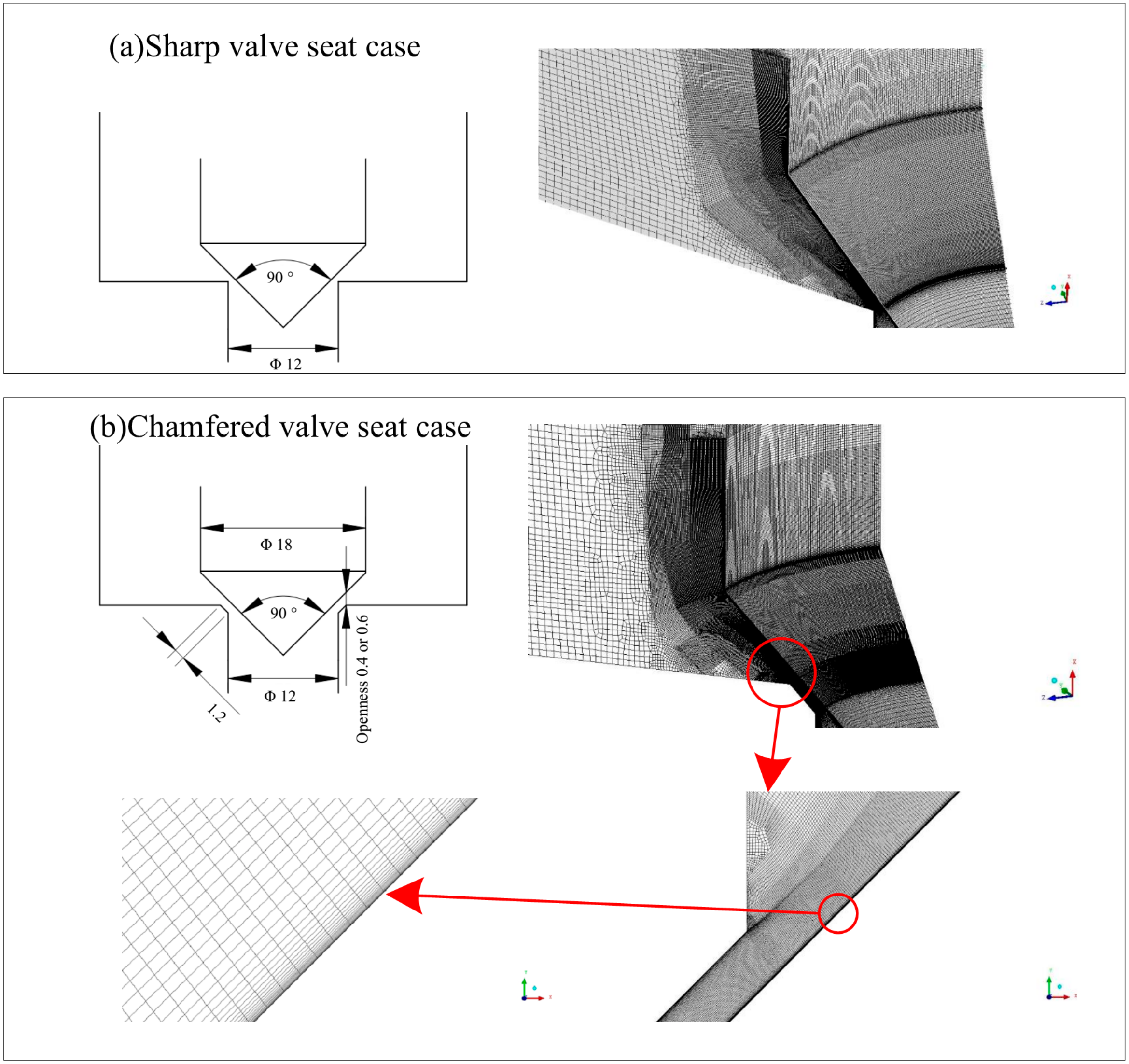
The geometric structure of the poppet valve is offered by Figure 1, which also includes the grid model. The computational domain covers a sector of 90 or 45 degrees depending on used fluid medium and valve seat structure. In the current investigation, the openness is set as 0.4 mm only in Section 3.2, which offers a validation study for the numerical method by means of time-average pressure distribution. And in the other cases, the openness is 0.6 mm. The total amount of calculation grid is approximately 5 million and 4.8 million for the water-flow case in poppet valves with sharp and chamfered valve seat, respectively. To resolve the critical vortex dynamics on the wall shearing layer, the region neighboring to poppet wall is given specific treatment with a minimum thickness of 0.2 μm, which also ensures yplus < 1. The experimental data used for validation of the simulation results comes from a previous study with a half-cut prototype [4]. The fluid properties are listed in Table 2.
3. Results
3.1. Cavitation Morphology
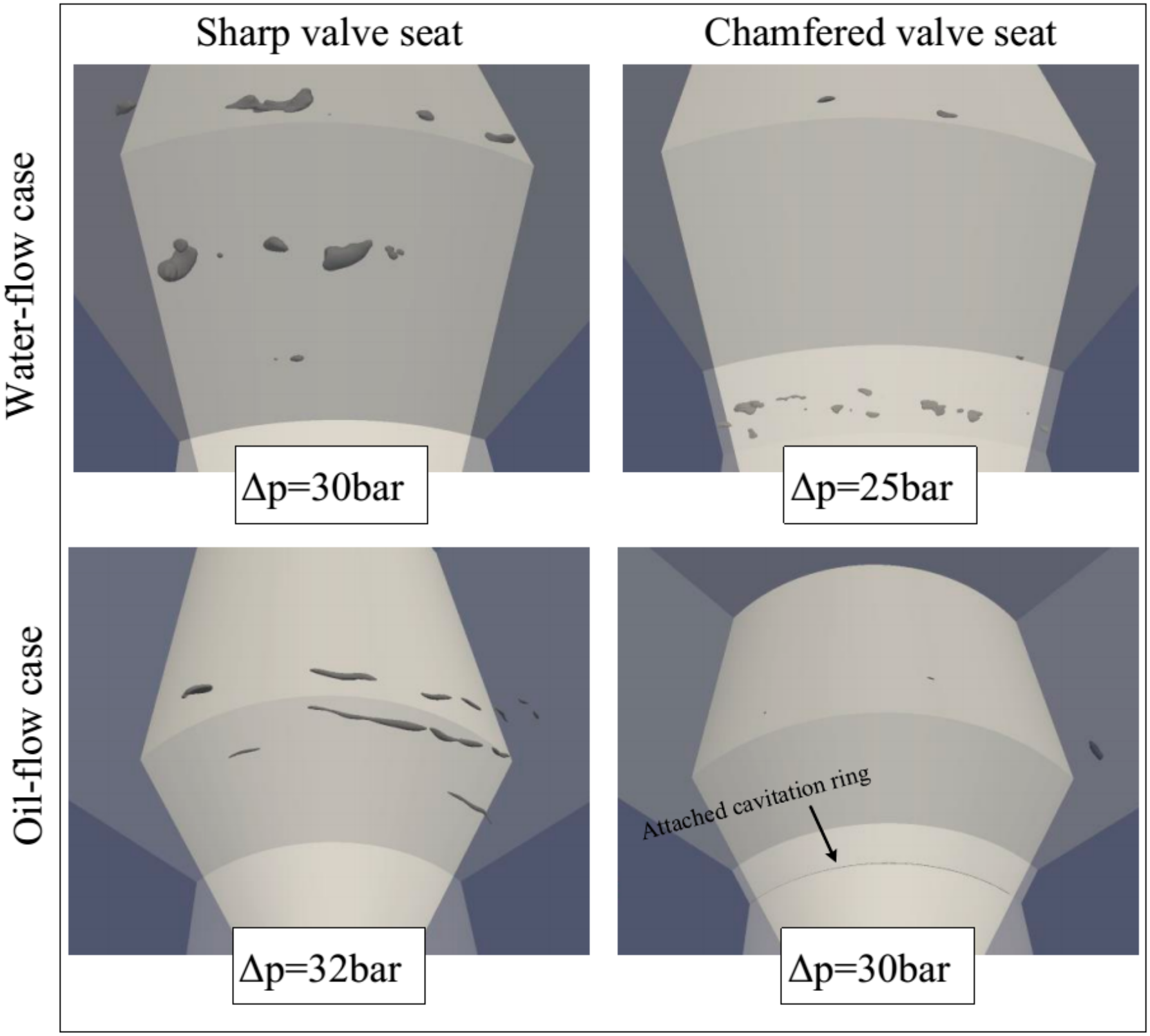
Figure 2 and Figure 3 provides the predicted cavitation morphology of water-flow case as well as the experimental images obtained under the same operating condition. For poppet valves with a sharp valve seat, cavitation is mainly triggered at two quite distanced positions at pressure drop of 40 bar, including the vortex cavitation within the shearing layer of potential core and the attached cavitation beyond the poppet trailing edge, as shown in Figure 2a. At a pressure drop of 45 bar, the cavitation intensity is substantially elevated, according to the dense distribution of cavitation structure. In experimental images, the cavitation within the shearing layer is initiated at a short distance of approximately 0.2 mm from the sharp valve seat, while the distance in the numerical prediction is approximately 0.2–0.3 mm, indicating a close agreement. The cavitation structure beyond the poppet trailing edge exhibits a sparse and scattered distribution and covers a region of 4.1 × 3.5 mm in simulation results, with an approximation to the experimental image of 3.9 mm × 4.0 mm, as shown in Figure 1b. In the chamfered valve seat configuration, cavitation as well occurs inside the chamfered groove at 30 bar pressure drop, besides the free shearing region of potential core and the poppet trailing edge, as shown in Figure 3. As the pressure drop is increased to 44 bar, the cavitation structure at the shearing layer of potential core extends upstream to the attached cavitation within the chamfered groove, and such phenomenon is present in both simulation and experiment images. The cavitation beyond the poppet trailing edge at 44-bar pressure drop covers an area of 4.3 × 3.0 mm in the simulation result, rather consistent with the experimental image of 4.4 × 3.4 mm.
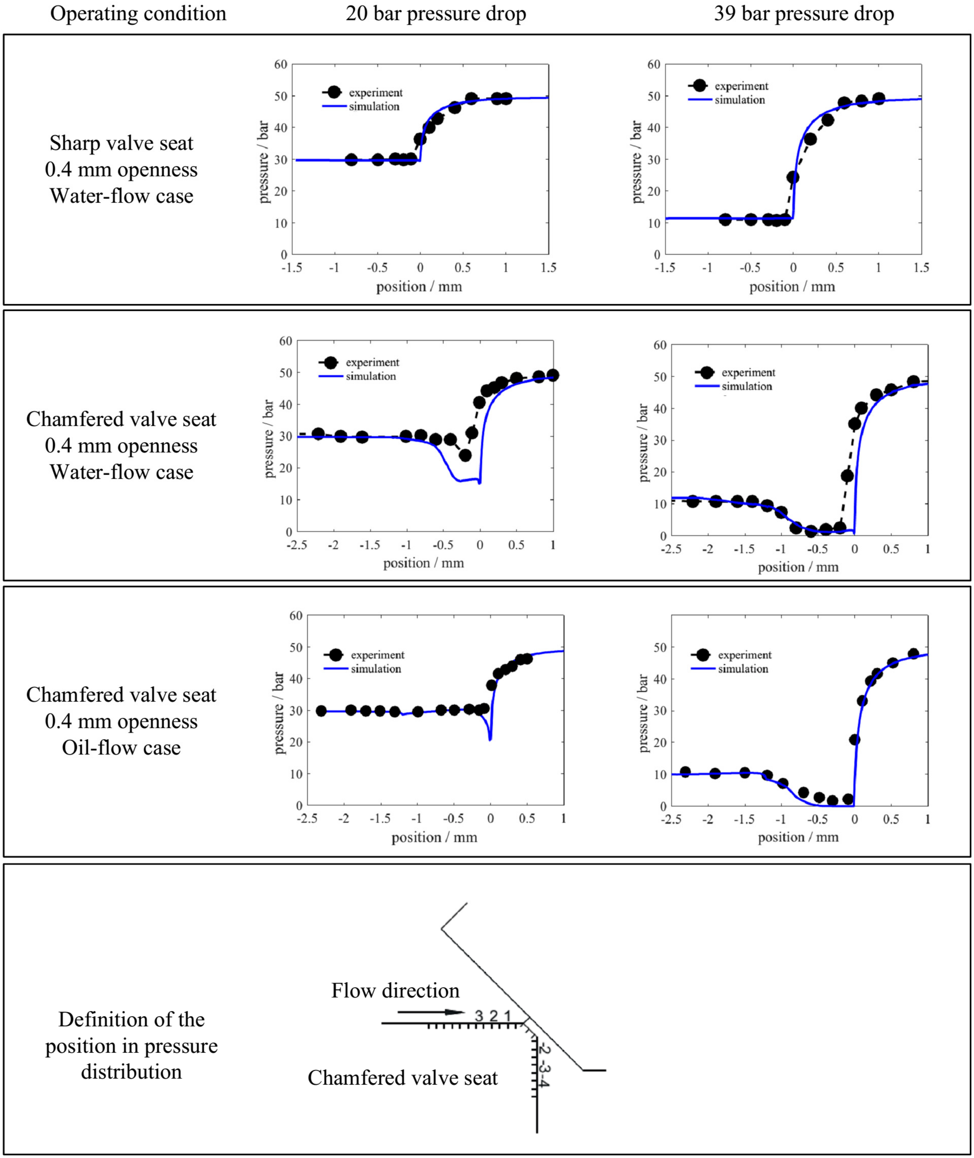
3.2. Pressure Distribution
The pressure drop on the valve seat wall is recorded with an openness of 0.4 mm. The operating condition of 20- and 39-bar pressure drop corresponds to the noncavitating case and cavitating case, respectively. In the sharp valve seat configuration, the water flow case presents a pressure drop at the sharp corner point, but the pressure drop thereby has a magnitude insufficient to induce cavitation even at the cavitating flow with 39-bar pressure drop, which is reproduced by the numerical method. The chamfered valve seat configuration also involves the oil flow case. Both the water-flow case and the oil-flow case exhibit a low-pressure region within the chamfered groove immediately neighboring to the inlet corner, such flow feature is recovered in the numerical method. The lowered precision in water-flow case in Figure 4 is mainly attributed the experimental prototype inevitably having a minor rounding at the inlet corner of chamfered groove, since the water flow case has a higher Re number, and consequently, increased sensitivity to the deviation in geometric structure. Such a rounding structure was reported as an effective method for cavitation suppression, particularly for the stably attached cavitation [20].
4. Discussion
4.1. Viscosity Effect on Vortex Cavitation and Potential Core
4.1.1. Difference in Vortex Cavitation and Potential Core in the Sharp Valve Seat Configuration
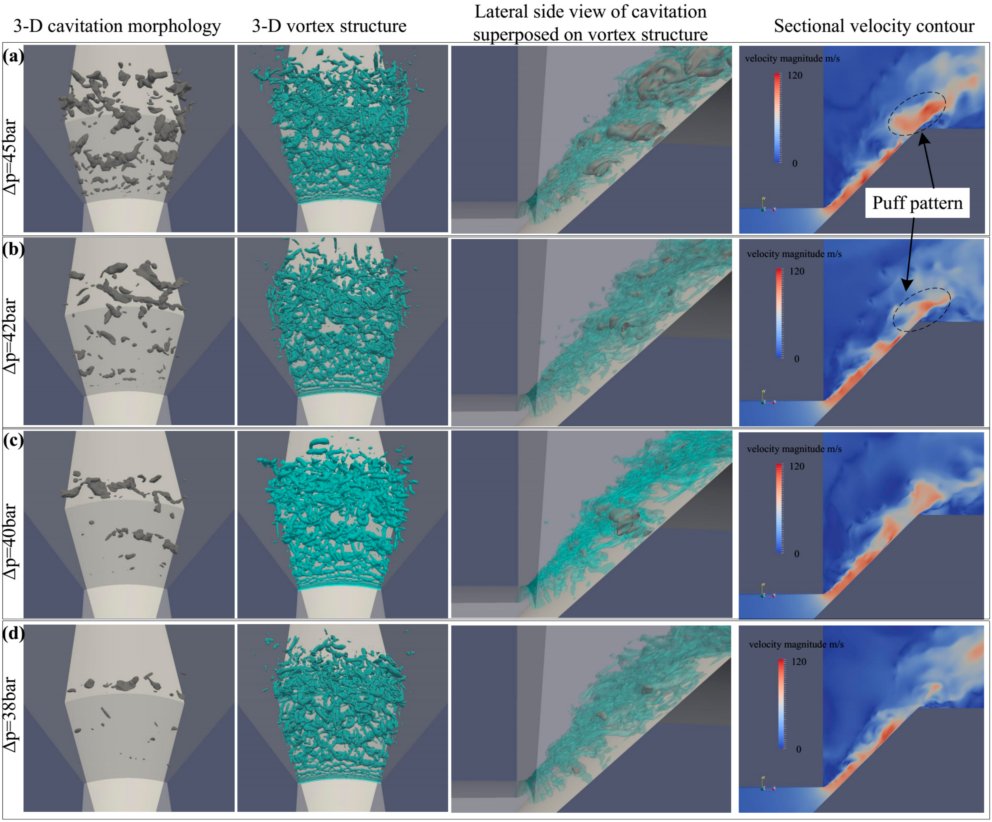
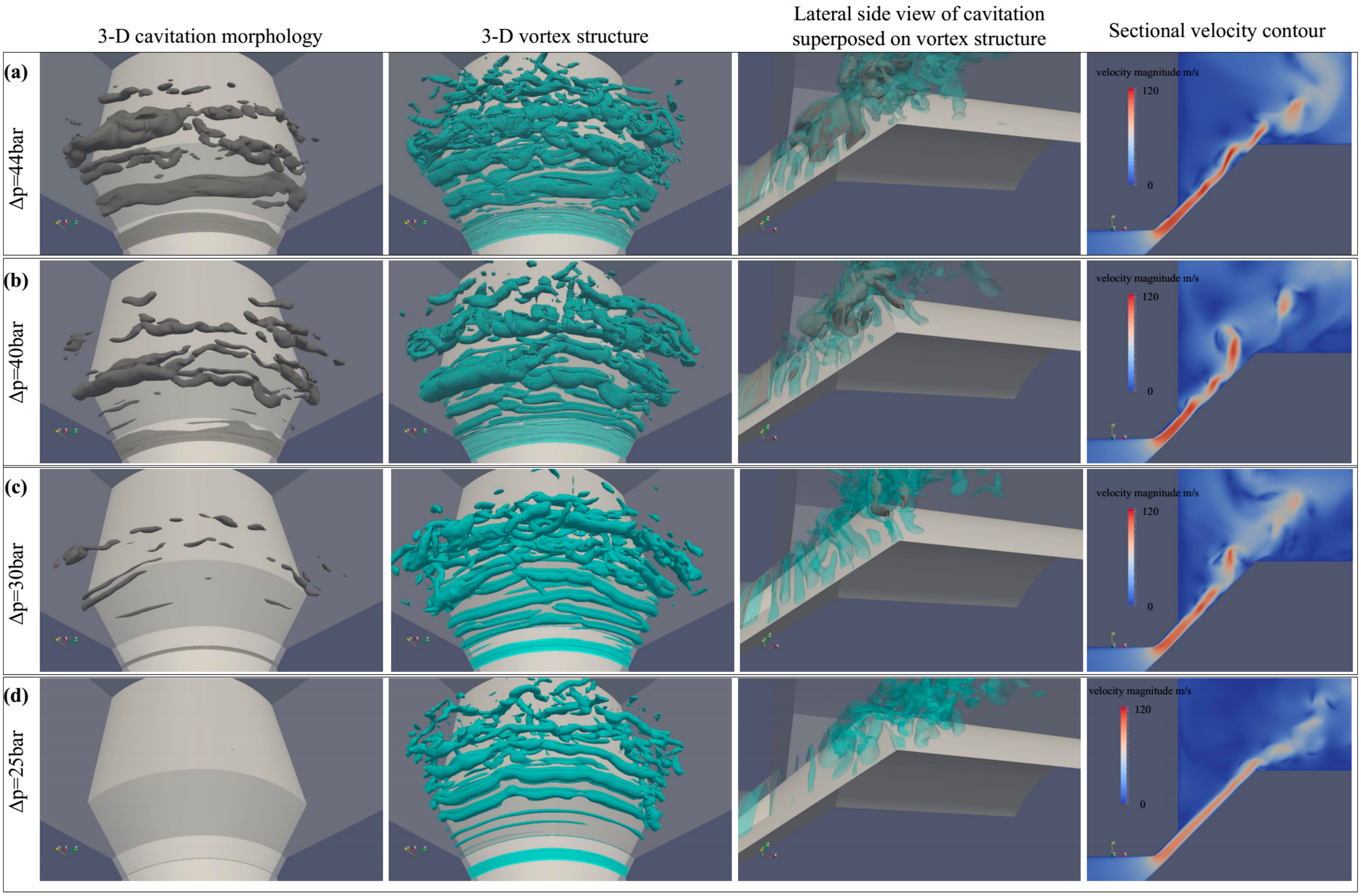
As shown in Figure 5, cavitation morphology is mainly located at two positions for water-flow inside the poppet valve with a sharp valve seat, categorized as vortex cavitation in the shearing region of the potential core and attached cavitation at the poppet trailing edge, respectively. The vortex cavitation, according to simulation results of Figure 5, follows a discontinuous distribution, while the continuous cavitation morphology in experimental images of Figure 5b might be misguiding due to the background blurring of super-imposed cavitation structure at varied azimuthal angles. In the oil-flow case, attached cavitation at the poppet trailing edge becomes almost negligible even at pressure drop of 45 bar, as shown in Figure 6. The vortex cavitation is closely correlated with vortex dynamics, and specifically with the coherent structure in the case of jet flow [14]. In contrast, the attached cavitation is mainly governed by inertial factor or flow separation, as in the typical case of circular nozzle cavitation and hydrofoil cavitation. The potential core undergoes a more aggressive break-up behavior prior to the poppet trailing edge in the water-flow case, contributing to the puff structure, in comparison to the waving pattern in the oil flow case, as indicated by the sectional velocity contour in Figure 5 and Figure 6.
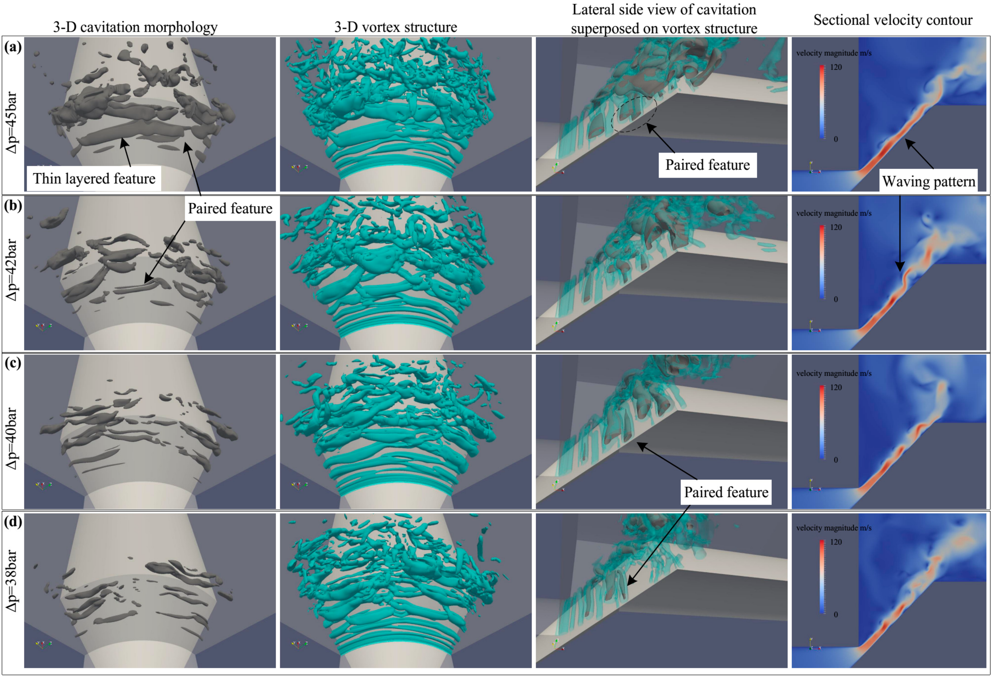
With a careful examination of the two cases, several discrepancies regarding vortex cavitation could be generalized as follows. Firstly, vortex cavitation is incepted earlier in the water flow at approximately 0.2 mm (quite close to the value 0.2–0.3 mm in experimental images as in Figure 2) after the inlet clearance at 45-bar pressure drop, while vortex cavitation is incepted at approximately 1.3 mm in oil flow case. The difference is mainly due to the higher Reynolds number in water flow, which leads to a stronger laminar-turbulent transition process of the jet flow. Consequently, vortex structure is developed quicker for water jet flow, and the induced pressure drop at the vortex core with a sufficient level to trigger cavitation occurs closer to the clearance, causing an earlier cavitation inception for the water-flow case. Secondly, the vortex cavitation is primarily limited to the free shearing side of the potential core for the water-flow case, whereas the oil-flow case also exhibits cavitation structure with a comparable size at the wall shearing side, and such delicately arranged vortex cavitation rings constitute a distinctive paired structure. Furthermore, the vortex cavitation in the oil-flow case has stronger axis-symmetry, and thus enhanced circumferential coherence. Thirdly, the vortex cavitation at the free shearing side in oil-flow case tends to assume a thin layer feature as shown in Figure 6a, which might be a result of the higher shearing intensity from the larger liquid viscosity. Fourthly, through multiple pairing mechanism of vortex cavitation, vortex cavitation in the form of a large bubble cluster is created at the rear part close to the poppet trailing edge at pressure drop of 45 bar in both water- and oil-flow case. However, the bubble cluster in water-flow consists of several separated bubbles with relatively small size and high 3-dimensionality as shown in Figure 5a, while the bubble cluster in oil-flow case involves several interconnected cavities of relatively large size, which preserves essential coherence as exhibited in Figure 6a.
4.1.2. Difference in Vortex Cavitation and Potential Core in the Chamfered Valve Seat Configuration
As shown in Figure 7 and Figure 8, for both water- and oil-flow case, cavitation morphology is also present inside the chamfered groove due to the vena-contracta phenomenon, contributing to increased volume of the vortex cavitation, particularly the bubble cloud in the water-flow case, as shown in Figure 7a. Consequently, the jet potential core is fragmented more violently than that in the poppet with a sharp valve seat. However, the puff feature in the water-flow case and the waving pattern in the oil-flow case are both distinguishable, as indicated by the sectional velocity contour in Figure 7 and Figure 8.
The most significant difference between the two cases in terms of vortex cavitation refers to the thin layer feature of the vortex cavitation ring within the free shearing layer and the paired vortex cavitation in oil flow case. The thin layer feature is a result of the strong shearing intensity, as mentioned in the sharp valve seat case. The persistent presence of paired configuration of vortex cavitation in both sharp and chamfered valve seat confirms that such discrepancy is a common flow phenomenon as a result of the viscosity effect irrespective of the valve seat configuration. As mentioned earlier, the vortex cavitation of water-flow case at 44 bar pressure drop could extend upstream to the attached cavitation within the chamfered groove, as shown in Figure 7a,b. Due to the detached cavitation from the chamfered groove, the vortex cavitation at the free shearing layer exhibits a clearly larger volume, with the appearance of a circumferentially-aligned bubble cloud with strong 3-dimensionality, as shown in Figure 7a,b. In contrast, the oil-flow case presents vortex cavitation with favorable circumferential symmetry, as exhibited in Figure 8a,b.
4.1.3. Discussion on Viscosity Effect on Vortex Cavitation and Potential Core
Difference in Circumferential Coherence and 3-Dimensionality
As a conclusion from the above analysis in terms of vortex cavitation, the evolution of vortex cavitation in the water-flow case generally is accompanied by a fast development process of 3-dimensionality, while vortex cavitation in oil flow retains preferable circumferential coherence, as shown in Figure 5, Figure 6, Figure 7 and Figure 8. It seems that the viscosity effect tends to retard the evolution of vortex cavitation. Such difference is highly correlated with the vortex dynamics and could be reasonably explained with the corresponding vortex structure. Figure 5, Figure 6, Figure 7 and Figure 8 also include the 3-D view of the vortex cavitation and vortex structure identified with Q-criterion. Due to the higher Re Number in water flow case, the laminar–turbulent transition process is rather fierce and fast. The coherent vortex structure originating from the Kelvin-Helmholtz instability inside the poppet valve with a sharp valve seat achieves a sufficiently high intensity. In the water-flow case, the fast-evolving vortex triggers cavitation at a more upstream region as a result of the pressure drop at vortex core. Subsequently, the vortex-cavitation interaction also facilitates the development of 3-dimensional vortex structure, conducive to the further break-up of vortex ring into several segments. Consequently, the downstream bubble cloud appears as several separated 3-dimensional bubble clusters. On the contrary, the transition process is delayed by the higher viscosity of mineral oil, which also contributes to the stronger stretching effect imposed on the cavitating vortex. Consequently, the vortex cavitation at the free shearing layer assumes a thin layer feature with favorable coherence. For the poppet valve with a chamfered valve seat, the vortex or cavitation structure at the free shearing layer originates from the chamfered groove. As a consequence of the uniform/concurrent detachment behavior of attached cavitation within the chamfered groove, the water-flow case occasionally exhibits vortex cavitation with an extremely huge volume and a circumferential alignment. Similarly, due to the deviation in viscous effect, the vortex cavitation generally displays stronger 3-dimensionality in the water-flow case, as indicated by the comparison between Figure 7a,b and Figure 8a,b.
By comparing the vortex structure evolution between water- and oil-flow case in Figure 5, Figure 6, Figure 7 and Figure 8, another important fact could be confirmed. The oil-flow case only involves the cross-linking feature with the formation of bubble cloud, which is categorized as an intermediate state between growth and break-down of coherent structure. Meanwhile, it also should be mentioned that either 3-dimensional vortex structure or cavitation structure only appears at the rear region corresponding to the collapse of cavitation. Thus, it could be concluded that the 3-dimensionality mainly comes from the collapse of vortex cavitation. On the contrary, the vortex in the water-flow case exhibits significant 3-dimensionality at the region immediately downstream of valve seat, even at the case of Figure 5d, where cavitation is absent thereby with the development of streamwise vortex. Consequently, the 3-dimensional vortex in the water-flow case primarily comes from the vortex evolution process, indicating the prevalent role of vortex dynamics in the vortex-cavitation interaction.
Paired Vortex Cavitation in Oil-Flow Case
Another interesting problem is raised regarding the paired configuration only in the oil-flow case. As shown in Figure 6 and Figure 8, in both sharp and chamfered valve seat, the water-flow case mainly exhibits cavitation in the free shearing side, while the oil-flow case also produces profound cavitation in the wall shearing side, which together with the vortex cavitation in the free shearing side constitutes the paired configuration. According to the detailed vortex structure in poppet valves with either sharp or chamfered valve seat in Figure 9a–d, a same phenomenon in each exhibited oil-flow case refers to the large-scale vortex structure within the wall shearing layer of the potential core. In the water-flow case, small-size vortex structures with a thin layer feature are developed within the thin shearing layer in the poppet valve with a sharp valve seat, as shown in Figure 9e. For poppet valves with a chamfered valve seat as exhibited in Figure 7a and Figure 9f, the thin layered vortex even triggers a thin cavity, probably due to the imposed chamfered groove, which confines the viscous diffusion of the jet potential core and contributes to an enhanced shearing intensity within the wall shearing layer. However, due to the diverging potential core and limited thickness of wall shearing layer, the thin layered vortex fails to achieve a size comparable to the counterpart in the oil case. In contrast, in the oil-flow case, the wall shearing layer has a thickness comparative to the free shearing layer. And the mild laminar-turbulent transition process conduces to the gradual growth of the vortex ring within the free shearing layer into larger size comparable to the potential core thickness before saturation, which facilitates the vortex development across the potential core at the wall shearing side. Therefore, the two vortexes at either side of potential core exert an interactive effect to each other, and constitute the paired configuration across the potential core, which is responsible for the waving pattern of the potential core in the oil-flow case. Such an interaction could be explained according to Kutta–Joukowski theorem [21]. The counter-rotating vortexes at either side of the potential core give rise to the opposite forces exerted on the two vortexes and further to the produced waving pattern. The persistent presence of paired configuration of vortex cavitation in oil-flow case suggests that such discrepancy is a common flow phenomenon as a result of the viscosity effect, irrespective of the valve seat structure. Figure 9 also includes a sensitivity study concerning viscosity effect on flow dynamics such as jet potential core pattern and vortex structure organization. As shown in Figure 9g, the waving pattern is created at kinematic viscosity of 2.2 × 10⁻⁵, and obvious paired structure appears at kinematic viscosity of 3.2 × 10⁻⁵.
Thin Layer Feature
In the oil-flow case, the vortex cavitation within the free shearing layer displays more evidently the feature as a thin layer. Such a difference could be interpreted by the higher viscosity of mineral oil, which contributes to a stronger shearing effect under condition of the same velocity gradient. Actually, the thin layer feature is also quite evident in the water-flow case for incepting vortex cavitation at both free shearing layer as shown in Figure 5a and wall shearing layer as shown in Figure 7a. But the fast development of 3-dimensional vortices significantly attenuates the shearing intensity on the cavity structure. Such thin layered feature of vortex cavitation bears great resemblance to the stress-induced cavitation proposed by Joseph [22]. Joseph stated a case of cavitation inception through direct rupturing of a liquid by sufficiently strong shearing. However, the vortex cavitation in the current study cases exhibits a bit difference that a vortex is created first with the subsequent development to trigger cavitation in the core. It should be mentioned that the vortex structure is visualized with different magnitude for oil and water case (in Figure 5, Figure 6, Figure 7 and Figure 8), indicating the higher velocity gradient, i.e., circulating strength, in the water-flow case. But the wall-shearing-induced cavitation is primarily more evident in the oil-flow case, as a consequence of the higher viscosity.
Potential Core Pattern
The last issue associated with the viscosity effect refers to Re Number effect. According to the evolution of potential core, the water-flow case of higher Re produces disruption of the potential core at the rear part, contributing to the puff pattern as proposed by Crow and Champagne (1971). In comparison, the oil case of low Re produces waving of the potential core at the rear part, contributing to the waving pattern as proposed by Crow and Champagne (1971). Such a difference of potential core is a result of the advancing Re Number effect, or specifically the shearing layer thickness and transition process. It also could be noticed that flow separation at poppet wall side is quite evident in the oil-flow case for both sharp and chamfered valve seat structure. But in the water case, such flow separation is negligible even in the case of chamfered valve seat structure due to the much smaller size of the vortex at the wall shearing layer. In the water-flow case, the stronger transition process disrupts the coherent vortex ring, and the produced highly 3-dimensional bubble cluster tends to tears the potential core apart, responsible for the establishment of the puff-like potential core at the rear region. As reported by Hussain [23], the water-flow case with puff pattern is similar to the jet column mode with penetration of the vortex through the jet potential core, while the oil-flow case of waving pattern shares similitude to the shear layer mode without an overall disruption of the potential core by the vortex, as explained in the aforementioned interaction between the two paired vortexes. Such difference in vortex cavitation as a consequence of Re Number variation is found in a previous investigation regarding to circular jet flow by Gopalan et al. [24]. Potential core dynamics could be fundamentally explained as a consequence of Re Number effects.
4.2. Viscosity Effect on Cavitation Inception
The difference in flow dynamics also leads to variation in the inceptive cavitation morphology. Figure 10 illustrates the cavitation inception for the four cases. For the poppet valve with a sharp valve seat, cavitation inception occurred approximately at pressure drop of 30 bar and 32 bar for the water- and oil-flow, respectively. The first appearance of cavitation in the oil-flow is located within the free shearing layer as transitory vortex cavitation, while the inceptive cavitation in the water-flow case involves additionally the attached cavitation at the poppet trailing edge with a comparable size. It suggests that under the operating condition of cavitation inception, the attached cavitation at the poppet trailing edge, which in the water-flow case has a size comparable to the vortex cavitation within the free shearing layer, is absent in the oil-flow case. For the poppet valve with a chamfered valve seat, the earliest traces of cavitation are mainly initiated as attached cavitation within the chamfered groove at pressure drop of 25 and 30 bar for water- and oil-flow case, respectively. However, the inceptive cavitation morphology is stably organized as an attached cavity ring, while that in the water-flow case displays the feature as detached vortex cavitation, as shown in Figure 10. And the attached cavitation at the poppet trailing edge is evidently present neither in the water- nor the oil-flow case. The difference in either susceptibility to cavitation or inceptive cavitation morphology is undeniably correlated with flow dynamics. Due to higher viscosity, the oil-flow case tends to facilitate shearing strength at the free shearing layer, and suppress flow separation and the resulted detached vortex, interpreting the deviation in inceptive cavitation morphology.
4.3. Viscosity Effect on Attached Cavitation
4.3.1. Attached Cavitation at the Poppet Trailing Edge
Concerning the attached cavitation at the poppet trailing edge, there are also two discrepancies between the water- and oil-flow case. Firstly, in oil cavitating flow, the attached cavitation at the poppet trailing edge is essentially negligible even at pressure drop over 40 bar, where vortex cavitation assumes a profound volume, as shown in Figure 6 and Figure 8. In contrast, the attached cavitation at the poppet trailing edge displays a comparable size to either vortex cavitation or attached cavitation within the chamfered groove. Such difference is demonstrated by the time-mean vapor distribution in Figure 11 and could be interpreted according to the flow velocity contour. As shown in Figure 5, Figure 6, Figure 7 and Figure 8, the potential core of oil jet flow has a wall shearing layer with larger thickness due to the higher viscous effect. The time-mean velocity distribution presented by Figure 12 indicates the oil-flow case has a smaller gradient at the poppet trailing edge, conducive to the suppression of the flow separation. Furthermore, the oil jet potential core follows a waving pattern at the poppet trailing edge, while the water potential core assumes a puff pattern, as analyzed above incorporating the summary of jet flow by Crow and Champagne [25]. The intermittently-passing puff structure leads to stronger alternating velocity pulsation than the waving potential core, as shown in Figure 5, Figure 6, Figure 7 and Figure 8. Both factors in oil flow case, including the thick wall shearing layer thickness and the waving pattern, tend to suppress the flow separation beyond the trailing edge as well as the induced attached cavitation.
Secondly, due to the involvement of vortex cavitation from upstream, the attached cavitation in either water- or oil-flow case could not be fully developed independently to display the self-resonant unsteady behavior as widely observed in foil cavitation. The whole process involves an interaction between the two kinds of cavitation. The evolution between the attached cavitation and vortex cavitation follows a quite different pattern for the two cases. In water jet flow, when passing across the trailing edge, the created cavitating vortex lumps also involves vortex cavities almost neighboring to the poppet wall surface. Consequently, the wall side vortex cavity gets in direct contact with the attached cavitation, and produces a mergence with the attached cavitation straightforward, facilitating detachment of the cavity initiated at the poppet trailing edge. Meanwhile, the detached cavitation tends to draw the shed cavitating vortex towards to the poppet wall, further contributing to the growth of the amalgamated cavitation. As shown in Figure 13a, the attached cavitation at the poppet trailing edge with only an originally small size undergoes an aggressive expansion with the involvement of the shed cavitating vortex, producing a detached cavity with a massive volume. Comparing Figure 5 and Figure 7, the shed vortex cavitation has a larger volume for the poppet with a chamfered groove, and the larger entrained cavitating vortex produces a higher contribution to the growth of the detached cavitation at the poppet trailing edge. Therefore, the attached cavitation at the poppet trailing edge has larger size in Figure 3a than in Figure 2. In the oil-flow case, only non-cavitating vortex is created at the poppet trailing edge, most of the time. And the shed vortex cavitation from upstream favors the detachment of the vortex due to flow separation at the poppet trailing edge. In return, the detached vortex gets entrained by the shed cavitating vortex. Consequently, the shed cavitating vortex experiences a secondary growth beyond the poppet trailing edge, as shown in Figure 14b. Originally, the vortex at the wall side has a smaller size than the paired counterpart at the free shearing side. However, as a result of the secondary growth, the wall side vortex beyond the poppet trailing edge becomes stronger than the other side, as indicated by the time-mean vapor distribution in Figure 11 and the pressure contour in Figure 13. In summary, the shed cavitating vortex entraps the detached vortex in the oil-flow case, whereas the shed cavitating vortex is entrained by the attached cavitation at the poppet trailing edge in the water-flow case. Therefore, the cavitation distribution as well as the low-pressure region biases towards to the poppet wall in the water-flow case, as shown in Figure 13.
4.3.2. Attached Cavitation within the Chamfered Groove
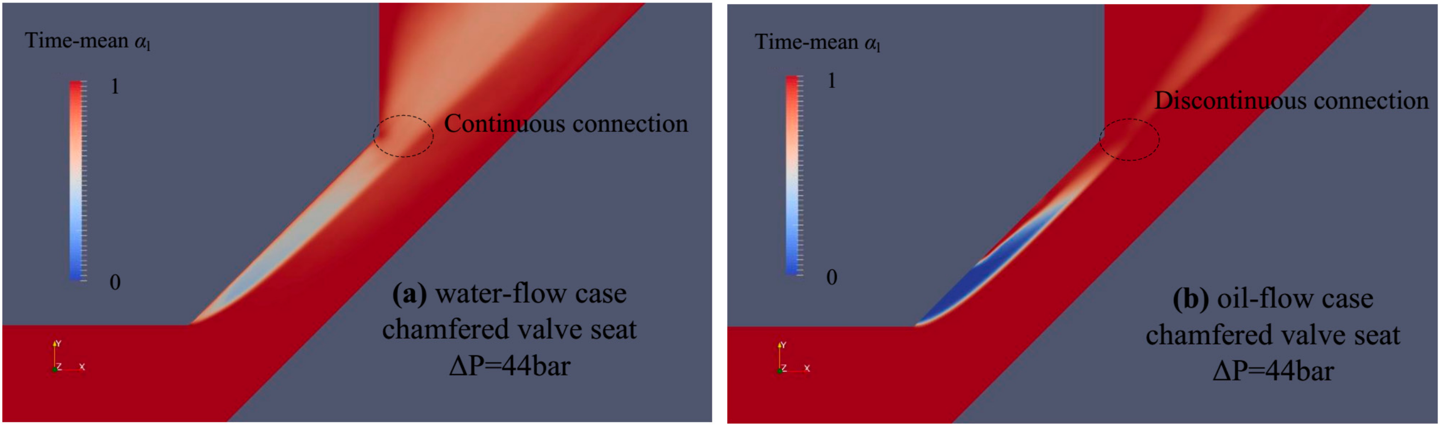
Figure 15 presents the time-mean cavitation inside the chamfered groove with a partial enlarged view of Figure 12. The oil-flow case is featured with an extremely high vapor content within the first half of the chamfered groove, indicating the constant presence of attached cavitation at the immediate downstream of the inlet corner. On the contrary, the water-flow case displays a more dispersive distribution of vapor. Figure 16 offers the transient evolution of cavitation within the chamfered groove. The attached cavity in the oil-flow case, featured with a sheet appearance, adheres constantly to the first half of the chamfered groove regardless of the transient variation. In contrast, the attach cavitation in the water flow case exhibits a more consecutive detachment behavior, instead of a persistent attachment to the inlet corner of the chamfered groove. The increased stability of the attached cavity at the inlet corner in the oil-flow case is associated with the elevated shearing intensity due to high viscosity, which produces a lasting rupture of the fluid and contributes to a high liquid tension even at the rear part. Such a phenomenon is consistent with the theory of shearing-stress-induced cavitation developed by Joseph [22]. As reported by Egerer et al. [26], the flow through a rectangle orifice produces stable sheet cavity persistently attached on the wall surface under choking condition, and periodic shedding cavity under non-choking condition, respectively. Either increase in velocity gradient and viscosity contributes to the shearing effect, and thus, the attached cavitation inside the chamfered groove in the oil-flow case appears as a sheet.
In addition, in water-flow case, the downstream vortex cavitation at the free shearing side extends to the dispersive distributed cavitation within the chamfered groove, as shown in Figure 15a. However, a clear discontinuity in the oil-flow case could be identified between the cavitation within the chamfered groove and the downstream vortex cavitation at the free shearing layer. Such difference suggests a stronger detachment behavior in the water-flow case. As shown in Figure 16a, due to the stronger shedding of cavity, the detachment behavior involves almost the whole attached cavitation in the water-flow case. As shown in Figure 16a, the scattered vortex structure at the rear part is distributed with chaotic orientation, similar to the case of detached cavitation in a rectangle orifice attributed by Egerer et al. [26] to vortex dynamics. Thus, the rear part of attached cavitation in water-flow case that consists of several separated cavitating vortex structures, is featured with high incoherence. As a comparison, merely the rear attached cavity is occasionally shed outside the groove into the downstream free shearing layer in the oil-flow case, as shown in Figure 16b, and only noncavitating vortex is shed downstream at the rest time. The corresponding vortex structure reveals the presence of detached vortex in the form of circumferential ring with favorable coherence irrelevant of the presence of detached cavitation, indicating the orderly state of the flow. The shed cavitation inside the chamfered groove from the attached cavitation may be governed by detached vortex dynamics from the groove inlet in the water flow case, which is featured with strong 3-dimensionality. In the oil flow case, the stable sheet cavitation produces a source of instability at the rear part, responsible for the generation of shed vortex ring with preservation of high coherence.
The final conclusion drawn from these analyses is that the difference of attached cavitation is a combined effect of both Re number and shearing strength. In the water flow case, the weaker shearing effect produces a detachment of the whole cavity, and the higher Re Number contributes to a faster evolution of 3-dimensional vortex. Consequently, the detached cavity is featured with strong streamwise-aligned vortex. In the oil flow case, the stronger shearing effect produces stable sheet cavity, and the detached vortex structure preserves favorable 2-dimensional symmetry partly due to the mild transition process. Consequently, the detached cavity is featured with axis-symmetry or coherence.
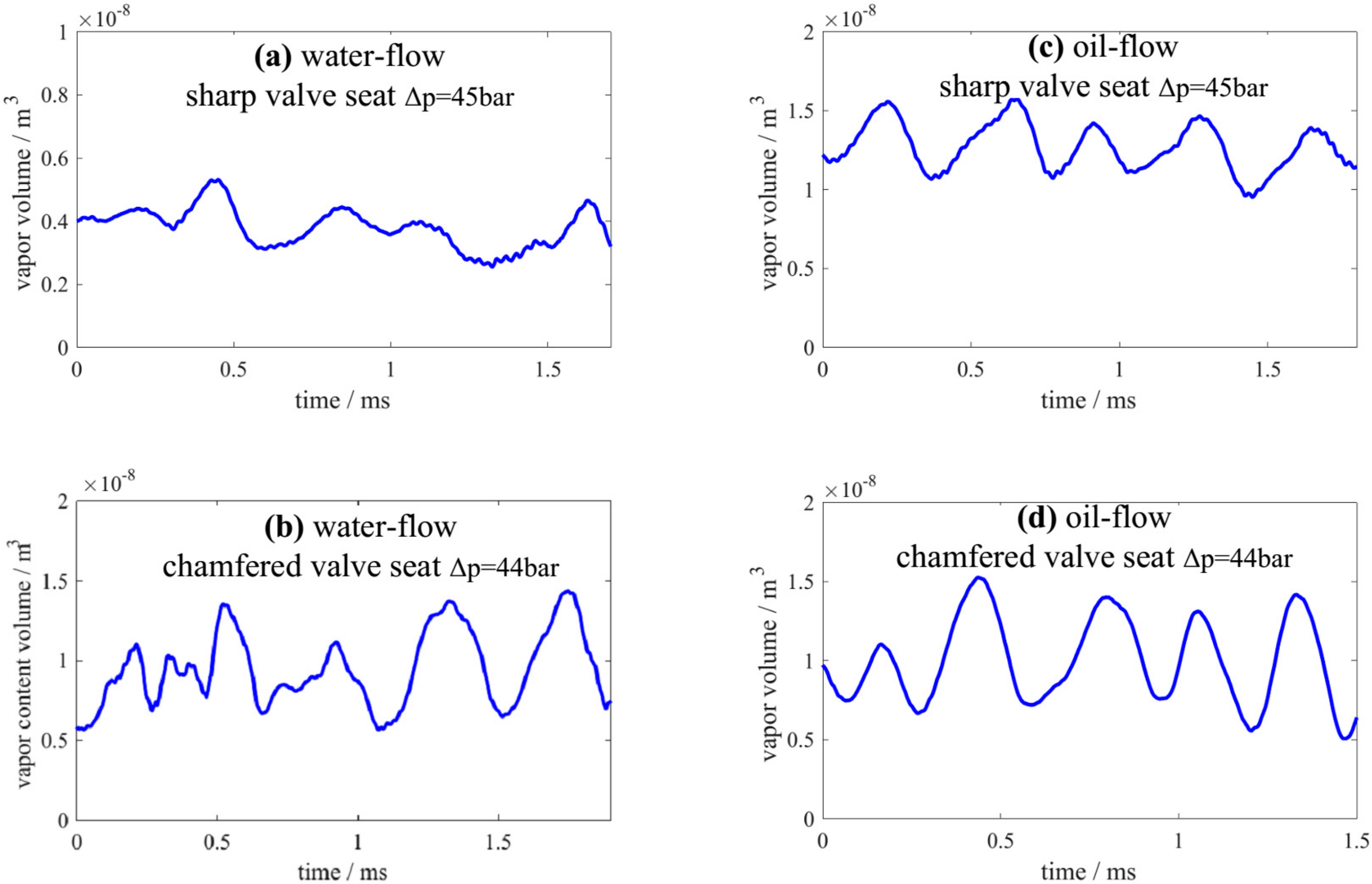
4.4. Viscosity Effect on Cyclic Performance
Figure 17 exhibits the time variation of total vapor volume for the four considered cases. Obviously, the periodic behavior of cavitation could be more clearly identified in the oil-flow case. As mentioned in previous section concerning the vortex-cavitation dynamics, the vortex dynamics plays a prevalent role in the water-flow case, whereas in the oil-flow case the cavitation dynamics serves as a significant contribution to the evolution of vortex. Therefore, the periodic performance of the cavitation in the oil-flow case is essentially preserved despite the involvement of vortex dynamics. Such interpretation is detailed in Figure 18 and Figure 19, which offer a typical cycle of the cavitation evolution process in the water- and oil-flow case, respectively. Both the water- and oil-flow case involves several times of shed vortex/cavitation from the chamfered groove, which displays an interaction with its neighboring one. In the water-flow case, the shed vortex cavitation at the outlet of chamfered groove is featured with strong 3-dimensionality, as mentioned above. Thus, the cavitation evolution suffers from a remarkable influence from vortex dynamics. In the oil-flow case, the shed vortex cavitation generally has an appearance of vortex ring with high coherence, and the interaction between successive shed vortex cavitation gives rise to insignificant stream-wise vortex, as shown in Figure 19. And the 3-dimensional vortex is primarily located at quite downstream region corresponding to cavitation collapse, which creates separated cavitation of disorderly alignment. It indicates the cavitation factor outweighs the vortex factor during the vortex-cavitation interaction.
5. Conclusions
Based on the comparative study, several important conclusions are drawn concerning the viscous effects.
- (1)
- Due to higher Re number, the water-flow case exhibits a stronger laminar-turbulent transition, resulting in a puff pattern of the potential core. Therefore, vortex dynamics plays a dominant role in the vortex-cavitation interaction, and the vortex cavitation at the free shearing side exhibits significant 3-dimensionality. Besides, the thin wall shearing layer contributes to the attached cavitation at the poppet trailing edge.
- (2)
- Due to the lower Re number, the oil-flow case has a mild laminar-turbulent transition and thicker wall shearing layer of the waving potential core, producing the paired vortex cavitation structure with remarkable coherence and suppressing the attached cavitation at the poppet trailing edge. The vortex dynamics produce a less significant effect in the vortex-cavitation interaction, compared to that of the water-flow case.
- (3)
- The variation in viscosity effect also leads to changes in the interactive evolution between cavitation structures initiated at varied regions. Due to the variation in wall shearing thickness, the cavitation at the poppet trailing edge entrains the shed vortex cavitation in the water-flow case, while the shed vortex cavitation entraps the detached vortex at the poppet trailing edge in the oil-flow case. Such different kinds of interactions between the vortex cavitation and attached cavitation facilitate growth of cavitation located at distinct regions beyond the poppet trailing edge.
- (4)
- The stronger vortex dynamics in the water-flow case produces a thorough detachment behavior for attached cavitation within the chamfered groove, leading to consecutive shedding of cavitating vortex with high 3-dimensionality. The higher viscosity of oil-flow produces a considerably larger shearing strength, leading to the stable attached cavitation within the upstream half of the chamfered groove. The rear part attached cavitation within the chamfered groove in the oil-flow case behaves as a source of instability, contributing to persistent shedding of non-cavitating vortex ring and periodic shedding of cavitating vortex ring.
- (5)
- Due to the prevalent vortex effect, the cavitation behavior in the oil-flow case suffers from a significant perturbation, while the periodic cavitation behavior sustains principally in the oil-flow case with a dominant cavitation effect in the vortex-cavitation interaction.
Author Contributions
Conceptualization, C.Y. and L.Z.; methodology, C.Y.; software, C.Y.; validation, C.Y. and S.L.; formal analysis, C.Y.; investigation, C.Y. and L.Z.; resources, C.Y. and L.Z.; data curation, C.Y. and L.Z.; writing—original draft preparation, C.Y. and L.Z.; writing—review and editing, C.Y. and L.Z.; visualization, C.Y. and L.Z.; supervision, H.L. and L.Z.; project administration, H.L. and L.Z.; funding acquisition, C.Y. and L.Z. All authors have read and agreed to the published version of the manuscript.
Funding
This research was funded by National Natural Science Foundation of China (No. 51975511), Guangdong Provincial Applied Science and Technology Research and Development Program (No. 2019A1515110844), and Youth Projects of Guangdong Education Department for Foundation Research and Applied Research (No. 2019KQNCX175).
Institutional Review Board Statement
Not applicable.
Informed Consent Statement
Not applicable.
Data Availability Statement
Not applicable.
Conflicts of Interest
The authors declare no conflict of interest.
References
- Oshima, S.; Ichikawa, T. Cavitation phenomena and performance of oil hydraulic poppet valve: 1st report mechanism of generation of cavitation and flow performance. Bull. JSME 1985, 28, 2264–2271. [Google Scholar] [CrossRef] [Green Version]
- Oshima, S.; Ichikawa, T. Cavitation phenomena and performance of oil hydraulic poppet valve: 2nd report, influence of the chamfer length of the seat and the flow performance. Bull. JSME 1985, 28, 2272–2279. [Google Scholar] [CrossRef] [Green Version]
- Ueno, H.; Okajima, A.; Muromiya, Y. Visualization of cavitating flow and numerical simulation of flow in a poppet valve. In Proceedings of the JFPS International Symposium on Fluid Power, Tokyo, Japan, 6 September 1993; pp. 385–390. [Google Scholar]
- Oshima, S.; Leino, T.; Linjama, M.; Koskinen, K.T.; Vilenius, M.J. Effect of cavitation in water hydraulic poppet valves. Int. J. Fluid Power 2001, 2, 5–13. [Google Scholar] [CrossRef]
- Liu, Y.S.; Huang, Y.; Li, Z.Y. Experimental investigation of flow and cavitation characteristics of a two-step throttle in water hydraulic valves. Proc. Inst. Mech. Eng. Part A J. Power Energy 2002, 216, 105–111. [Google Scholar] [CrossRef]
- Nie, S.; Huang, G.; Li, Y.; Yang, Y.; Zhu, Y. Research on low cavitation in water hydraulic two-stage throttle poppet valve. Proc. Inst. Mech. Eng. Part E J. Process. Mech. Eng. 2006, 220, 167–179. [Google Scholar] [CrossRef]
- Liang, J.; Luo, X.; Liu, Y.; Li, X.; Shi, T. A numerical investigation in effects of inlet pressure fluctuations on the flow and cavitation characteristics inside water hydraulic poppet valves. Int. J. Heat Mass Transf. 2016, 103, 684–700. [Google Scholar] [CrossRef]
- Han, M.; Liu, Y.; Wu, D.; Zhao, X.; Tan, H. A numerical investigation in characteristics of flow force under cavitation state inside the water hydraulic poppet valves. Int. J. Heat Mass Transf. 2017, 111, 1–16. [Google Scholar] [CrossRef]
- Saha, B.K.; Li, L.; Li, S. CFD investigations of flow field and cavitation phenomena in the pilot stage of deflector jet servo-valve. AIP Conf. Proc. 2019, 2073, 020025. [Google Scholar]
- Chen, M.; Aung, N.Z.; Li, S.; Zou, C. Effect of oil viscosity on self-excited noise production inside the pilot stage of a two-stage electrohydraulic servo valve. J. Fluids Eng. 2019, 141, 011106. [Google Scholar] [CrossRef]
- Agarwal, A.K.; Som, S.; Shukla, P.C.; Goyal, H.; Longman, D. In-nozzle flow and spray characteristics for mineral diesel, Karanja, and Jatropha biodiesels. Appl. Energy 2015, 156, 138–148. [Google Scholar] [CrossRef] [Green Version]
- Yuan, C.; Song, J.; Liu, M. Investigation of flow dynamics and governing mechanism of choked flow for cavitating jet in a poppet valve. Int. J. Heat Mass Transf. 2019, 129, 113–131. [Google Scholar] [CrossRef]
- Yuan, C.; Song, J.; Liu, M. Comparison of compressible and incompressible numerical methods in simulation of a cavitating jet through a poppet valve. Eng. Appl. Comput. Fluid Mech. 2019, 13, 67–90. [Google Scholar] [CrossRef]
- Arndt, R.E. Cavitation in vortical flows. Ann. Rev. Fluid Mech. 2002, 34, 143–175. [Google Scholar] [CrossRef]
- Joseph, D.D. Cavitation and the state of stress in a flowing liquid. J. Fluid Mech. 1998, 366, 378. [Google Scholar] [CrossRef] [Green Version]
- Ubbink, O.; Issa, R.I. A method for capturing sharp fluid interfaces on arbitrary meshes. J. Comput. Phys. 1999, 153, 26–50. [Google Scholar] [CrossRef] [Green Version]
- Demirdžić, I.; Lilek, Ž.; Perić, M. A collocated finite volume method for predicting flows at all speeds. Int. J. Numer. Methods Fluids 1993, 16, 1029–1050. [Google Scholar] [CrossRef]
- Schnerr, G.H.; Sauer, J. Physical and numerical modeling of unsteady cavitation dynamics. In Proceedings of the Fourth International Conference on Multiphase Flow, New Orleans, LA, USA, 27 May–1 June 2001. [Google Scholar]
- Schmidt, D.P.; Corradini, M.L. The internal flow of diesel fuel injector nozzles: A review. Int. J. Engine Res. 2001, 2, 1–22. [Google Scholar] [CrossRef]
- Benajes, J.; Pastor, J.V.; Payri, R.; Plazas, A.H. Analysis of the influence of diesel nozzle geometry in the injection rate characteristic. J. Fluids Eng. 2004, 126, 63–71. [Google Scholar] [CrossRef]
- Long, X.; Cheng, H.; Ji, B.; Arndt, R.E.; Peng, X. Large eddy simulation and Euler–Lagrangian coupling investigation of the transient cavitating turbulent flow around a twisted hydrofoil. Int. J. Multiph. Flow 2018, 100, 41–56. [Google Scholar] [CrossRef]
- Joseph, D.D. Cavitation in a flowing liquid. Phy. Rev. E. 1995, 51, R1649. [Google Scholar] [CrossRef] [PubMed]
- Hussain, A.F. Coherent structures and turbulence. J. Fluid Mech. 1986, 173, 303–356. [Google Scholar] [CrossRef]
- Gopalan, S.; Katz, J.; Knio, O. The flow structure in the near field of jets and its effect on cavitation inception. J. Fluid Mech. 1999, 398, 1–43. [Google Scholar] [CrossRef] [Green Version]
- Crow, S.C.; Champagne, F.H. Orderly structure in jet turbulence. J. Fluid Mech. 1971, 48, 547–591. [Google Scholar] [CrossRef]
- Egerer, C.P.; Hickel, S.; Schmidt, S.J.; Adams, N.A. Large-eddy simulation of turbulent cavitating flow in a micro channel. Phys. Fluids 2014, 26, 085102. [Google Scholar] [CrossRef]
Figure 1.
Geometric structure of poppet valve and calculation grid for water-flow case (dimensions in mm).
Figure 1.
Geometric structure of poppet valve and calculation grid for water-flow case (dimensions in mm).

Figure 2.
Cavitation morphology identified by iso-surface αl = 70% in simulation for sharp valve seat case (experimental image at left side by Oshima et al. [4] is also included for comparison). (a) water flow with 45 bar pressure drop through sharp valve of 0.6 mm openness; (b) water flow with 40 bar pressure drop through sharp valve of 0.6 mm openness.

Figure 3.
Cavitation morphology identified by iso-surface αl = 70% in simulation for chamfered valve seat case (experimental image at left side by Oshima et al. [4] is also included for comparison). (a) water flow with 44 bar pressure drop through chamfered valve of 0.6 mm openness; (b) water flow with 30 bar pressure drop through chamfered valve of 0.6 mm openness.

Figure 4.
Comparison between simulation and experimental data in terms of time-average pressure distribution, indicating consistence between experimental measurement and simulation.
Figure 4.
Comparison between simulation and experimental data in terms of time-average pressure distribution, indicating consistence between experimental measurement and simulation.

Figure 5.
Simulation results for water cavitating flow inside a poppet valve with a sharp valve seat. Cavitation and vortex structure are identified with iso-surface of αl = 70% and Q = 1 × 10¹⁰. Common puff pattern in each operating condition is produced at downstream region mainly due to severe transition process. (a) 45 bar pressure drop; (b) 42 bar pressure drop; (c) 40 bar pressure drop; (d) 38 bar pressure drop.

Figure 6.
Simulation results for oil cavitating flow inside a poppet valve with a sharp valve seat. Cavitation and vortex structure are identified with iso-surface of αl = 70% and Q = 3 × 10⁹. Persistent presence of paired feature and waving pattern in each operating condition is mainly due to relatively mild transition process. (a) 45 bar pressure drop; (b) 42 bar pressure drop; (c) 40 bar pressure drop; (d) 38 bar pressure drop.

Figure 7.
Simulation results for water cavitating flow inside a poppet valve of a chamfered valve seat with different pressure drop ranging from 25 to 44 bar. Cavitation and vortex structure are identified with iso-surface of αl = 70% and Q = 1 × 10¹⁰. (a) 44 bar pressure drop; (b) 40 bar pressure drop; (c) 30 bar pressure drop; (d) 25 bar pressure drop.

Figure 8.
Simulation results for oil cavitating flow inside a poppet valve of a chamfered valve seat with different pressure drop ranging from 25 to 44 bar. The cavitation and vortex structure are identified with iso-surface of αl = 70% and Q = 3 × 10⁹. (a) 44 bar pressure drop; (b) 40 bar pressure drop; (c) 30 bar pressure drop; (d) 25 bar pressure drop.

Figure 9.
Detailed view of vortex structure in different poppet valves of 0.6 mm openness and different operating conditions, and sensitivity study on influence of viscosity on flow dynamics (a) oil flow inside poppet valve of sharp valve seat structure, with pressure drop of 45 bar; (b) oil flow inside poppet valve of sharp valve seat structure, with pressure drop of 38 bar; (c) oil flow inside poppet valve of chamfered valve seat structure, with pressure drop of 44 bar; (d) oil flow inside poppet valve of chamfered valve seat structure, with pressure drop of 30 bar; (e) water flow inside poppet valve of sharp valve seat structure, with pressure drop of 45 bar; (f) water flow inside poppet valve of chamfered valve seat structure, with pressure drop of 44 bar; (g) sensitivity of jet flow dynamics to variation of kinematic viscosity, pressure drop of 45 bar, sharp valve seat.

Figure 10.
Cavitation inception in four considered study cases. Cavitation inception in oil-flow case appears as ring structure, while water-flow case is featured with dispersive bubbles.
Figure 10.
Cavitation inception in four considered study cases. Cavitation inception in oil-flow case appears as ring structure, while water-flow case is featured with dispersive bubbles.

Figure 11.
Time-mean vapor distribution. Dashed ellipse indicates most concentrated vapor region at downstream of poppet trailing edge.
Figure 11.
Time-mean vapor distribution. Dashed ellipse indicates most concentrated vapor region at downstream of poppet trailing edge.

Figure 12.
Time-mean velocity magnitude contour. Velocity magnitude curve at right-side corresponds to black line in left contour.
Figure 12.
Time-mean velocity magnitude contour. Velocity magnitude curve at right-side corresponds to black line in left contour.

Figure 13.
Time-mean pressure distribution. Dashed ellipse indicates low-pressure region at downstream of poppet trailing edge.
Figure 13.
Time-mean pressure distribution. Dashed ellipse indicates low-pressure region at downstream of poppet trailing edge.

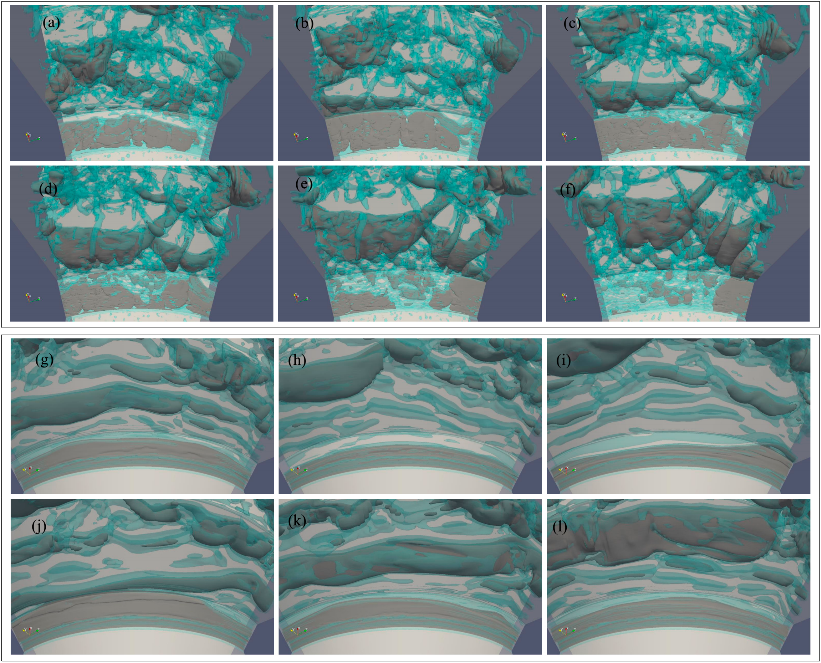
Figure 14.
Time-variation of attached cavitation at poppet trailing edge. (a–f) water flow case, sharp valve seat, Δp = 45 bar, time increment ΔT = 4 × 10⁻⁶ s; (g–l) oil flow case, sharp valve seat, Δp = 45 bar, time increment ΔT = 5 × 10⁻⁶ s.
Figure 14.
Time-variation of attached cavitation at poppet trailing edge. (a–f) water flow case, sharp valve seat, Δp = 45 bar, time increment ΔT = 4 × 10⁻⁶ s; (g–l) oil flow case, sharp valve seat, Δp = 45 bar, time increment ΔT = 5 × 10⁻⁶ s.

Figure 15.
Detailed view of cavitation within the chamfered groove.

Figure 16.
Time-variation of attached cavitation within chamfered groove. (a–f) water flow case, chamfered valve seat, Δp = 44 bar, time increment ΔT = 1.2 × 10⁻⁵ s; (g–l) oil flow case, chamfered valve seat, Δp = 44 bar, time increment ΔT = 2.5 × 10⁻⁵ s.
Figure 16.
Time-variation of attached cavitation within chamfered groove. (a–f) water flow case, chamfered valve seat, Δp = 44 bar, time increment ΔT = 1.2 × 10⁻⁵ s; (g–l) oil flow case, chamfered valve seat, Δp = 44 bar, time increment ΔT = 2.5 × 10⁻⁵ s.

Figure 17.
Temporal variation of total vapor volume for different poppet valves and operating conditions.
Figure 17.
Temporal variation of total vapor volume for different poppet valves and operating conditions.

Figure 18.
Transient cavitation evolution and total vapor volume within a complete cycle in water-flow case for poppet valve with a chamfered valve seat case at 44 bar pressure drop. (a–j) cavitation structure identified by the blue colored iso-surface αl = 90% at varied instants; (k) time-variation of total vapor volume with black solid boxes indicating instants corresponding to (a) to (j).

Figure 19.
Transient cavitation evolution and total vapor volume within a complete cycle in oil-flow case for poppet valve with a chamfered valve seat case at 44 bar pressure drop. (a–j) cavitation structure identified by dark colored iso-surface αl = 90% at varied instants; (k) time-variation of total vapor volume with black solid boxes indicating instants corresponding to (a) to (j).


Table 1.
Definition of variables.
| Variable | Definition |
|---|---|
| A | Volume content |
| Ρ | Density |
| Ψ | Compressibility |
| rRb | Cavitation model constant |
| ca | Artificial compression coefficient |
| Σ | Surface tension coefficient |
| Κ | Interface curvature |
| pv | Cavitation threshold pressure |
| Total mass transfer | |
| Mass transfer due to vaporization | |
| Mass transfer due to condensation | |
| rRb | Cavitation model constant |
| Ur | Interphase relative velocity |
| Τ | Local stress tensor |
Table 2.
Fluid property.
| Liquid Type | Mineral Oil #46 | Water |
|---|---|---|
| liquid density | 872 kg/m3 | 1000 kg/m3 |
| liquid dynamic viscosity | 0.042 N s/m2 | 0.001 N s/m2 |
| vapor pressure | 3000 pa | 2000 pa |
| vapor density | 0.13 kg/m3 | 0.02558 kg/m3 |
| vapor dynamic viscosity | 0.00572 N s/m2 | 0.00126 N s/m2 |
| temperature | 313 K | 313 K |
| surface tension | 0.03 N/m | 0.0782 N/m |
Publisher’s Note: MDPI stays neutral with regard to jurisdictional claims in published maps and institutional affiliations. |
© 2021 by the authors. Licensee MDPI, Basel, Switzerland. This article is an open access article distributed under the terms and conditions of the Creative Commons Attribution (CC BY) license (https://creativecommons.org/licenses/by/4.0/).
Share and Cite
MDPI and ACS Style
Yuan, C.; Zhu, L.; Liu, S.; Li, H. Examination of Viscosity Effect on Cavitating Flow inside Poppet Valves Based on a Numerical Study. Appl. Sci. 2021, 11, 11205. https://0-doi-org.brum.beds.ac.uk/10.3390/app112311205
AMA Style
Yuan C, Zhu L, Liu S, Li H. Examination of Viscosity Effect on Cavitating Flow inside Poppet Valves Based on a Numerical Study. Applied Sciences. 2021; 11(23):11205. https://0-doi-org.brum.beds.ac.uk/10.3390/app112311205
Chicago/Turabian StyleYuan, Cong, Lisha Zhu, Shiqi Liu, and He Li. 2021. "Examination of Viscosity Effect on Cavitating Flow inside Poppet Valves Based on a Numerical Study" Applied Sciences 11, no. 23: 11205. https://0-doi-org.brum.beds.ac.uk/10.3390/app112311205
Note that from the first issue of 2016, this journal uses article numbers instead of page numbers. See further details here.