Article

Experimental and Numerical Investigations on Fire-Resistance Performance of Precast Concrete Hollow-Core Slabs

1
Department of Architectural Engineering, University of Seoul, 163 Seoulsiripdaero, Dongdaemun-gu, Seoul 02504, Korea
2
Department of Architectural Engineering and Smart City Interdisciplinary Major Program, University of Seoul, 163 Seoulsiripdaero, Dongdaemun-gu, Seoul 02504, Korea
*
Author to whom correspondence should be addressed.
Submission received: 10 November 2021 / Revised: 30 November 2021 / Accepted: 2 December 2021 / Published: 4 December 2021
(This article belongs to the Special Issue New Challenges in Civil Structure for Fire Response)

Abstract

:
In this study, full-scale fire tests and finite element (FE) analyses are conducted to investigate the fire resistance performance of hollow-core slabs (HCSs) manufactured using the extrusion method. The deflection of the HCS specimens and the temperature distribution in the section according to the fire exposure time are measured and analyzed comprehensively, and the test results are compared with the FE analysis results. In addition, parametric analyses are conducted on 21 cases with the HCS depth, span length, hollow ratio in a section, cover thickness of concrete, and load ratio (i.e., the ratio of the external load to the ultimate load) as variables, based on which the fire resistance performance of the HCS according to each variable is investigated. The analysis results show that the load ratio is a key factor governing the fire resistance behavior of HCSs, whereas the effects of the cover thickness of concrete and the hollow ratio in a section are relatively slight within the range of variables examined in this study.

1. Introduction

Recently, the precast concrete (PC) method has garnered significant interest, and its demand in the construction field has increased [1,2]. The PC method offers several advantages over the reinforced concrete (RC) method in that it can minimize field work, including the installation of temporary equipment, and can therefore reduce construction periods and construction costs. In addition, most PC members are manufactured in factories, which facilitates the quality control of materials and minimizes waste and dust on construction sites [3,4]. Hence, the PC method has been actively applied to underground parking lots, semiconductor fabrication plants, and distribution warehouses [5,6].
The prestressed hollow-core slab (HCS) shown in Figure 1 is a representative PC slab that can reduce the amount of concrete required in manufacturing slabs as well as the self-weight of members by forming voids in the section, thereby facilitating the transport and lifting of members at the site. In addition, because prestress is introduced into the cross-section of the slab, the HCS exhibits excellent crack controllability and is advantageous for deflection control under service loads. For these reasons, it has been extensively applied worldwide [7,8].
For the HCS to be used as a flooring system, it must demonstrate flexural and shear capacities as well as fire resistance performance. In particular, compared with solid RC slabs, HCSs may exhibit relatively low fire resistance performance because of the voids formed in the cross-section; hence, the fire resistance performance of hollow-core slabs needs to be investigated. The most common approach for evaluating fire resistance of building elements, such as beams, columns, walls, and floors, is to perform fire resistance tests. Data from such tests can be utilized to establish fire resistance ratings of various structural members. Fire resistance tests are conducted in specially designed fire-testing furnaces with specific features and dimensions. During the test, the member or assembly is exposed to fire in which the temperature increases according to a standard fire curve. Fire resistance is usually expressed as the time at which the member or assembly meets the specified criteria of performance. Most design codes required three failure criteria that are to be satisfied during the standard fire resistance tests, which generally include an insulation criterion to limit the temperature rise and fire propagation, a stability criterion to prevent collapse or excessive deformation, and an integrity criterion to limit flame spread. Based on the time taken to reach the specified criteria, a fire-resistance rating is assigned for the member by typically rounding down to the nearest 30-min interval up to 2 h, after which hourly intervals are used. [9,10]. While many previous studies associated with HCSs have focused on the flexural and shear behaviors at room temperature [11,12,13,14,15,16,17,18,19,20], in recent years, several studies have been conducted to identify the structural behavior of HCSs under fire [21,22,23,24,25,26,27]; however, most of them are primarily associated with the analysis of the fire resistance performance of HCSs based on the finite element (FE) method. Therefore, full-scale fire tests of HCSs are still insufficient.
Buchanan et al. [22,28,29] performed an FE analysis on HCSs exposed to fire and proposed a simple method for structural engineers to model the fire resistance behavior of HCSs. In addition, they analyzed the effect of aspect ratio (slab width to slab span length) on the fire performance of hollow concrete slabs through additional analytical studies. Kodur et al. [30] applied a finite element-based numerical model built in ANSYS to evaluate the fire performance of HCS in realistic fire load scenarios that exist in parking structures. They clearly showed that the fire resistance was higher under realistic fire conditions than under the standard fire conditions. Aguado et al. [21] proposed a numerical model for investigating the thermomechanical behavior of an HCS and conducted a comparative analysis between the proposed model and the evaluation method presented in Eurocode 2 [31]. Albero et al. [23] conducted a numerical analysis on the fire behavior of slim-floor beams combined with HCSs as a flooring system and then analyzed the difference in fire resistance performance between integrated floor beams and shallow floor beams in detail. Pečenko et al. [24] proposed a computational model for HCSs under natural fire, especially considering material and geometric nonlinearities in addition to slip between concrete and prestressing strands. Meanwhile, other numerical studies have also been performed to identify the fire resistance performance of HCSs [25,26,27]. However, to verify the accuracy and rationality of the FE analysis, a comparative analysis of the fire resistance test results of HCSs is required. The FE model must be able to closely evaluate the behavior of the member observed in the experiment, such as the center deflection with respect to the fire exposure time and the temperature distribution in a section. However, the available fire test data of HCSs are insufficient, particularly for full-scale fire test data.
In this study, a full-scale fire resistance test was conducted on an HCS manufactured in an actual precast factory and used in practice. For the fire test, two HCS specimens with cross-sectional heights of 200 and 265 mm were fabricated. The deflection of the specimens according to the fire exposure time and the temperature distribution inside the concrete section were measured and analyzed comprehensively, and the fire resistance performance of the HCS specimens was evaluated based on the criteria presented in ISO 834-1 (International Organization for Standardization) [32]. In addition, FE analysis was performed considering heat transfer and material properties that change according to temperature, and the rationality of the FE model was verified by comparing it with the actual temperature and structural behaviors of the HCS specimens. Based on the verified FE model, a parametric analysis was conducted on 21 cases with the HCS depth, span length, hollow ratio in a section, cover thickness of concrete, and load ratio (i.e., the ratio of the external load to the ultimate load) as variables. Subsequently, the fire resistance performance of the HCS according to each variable was evaluated and discussed comprehensively.

2. Experimental Program
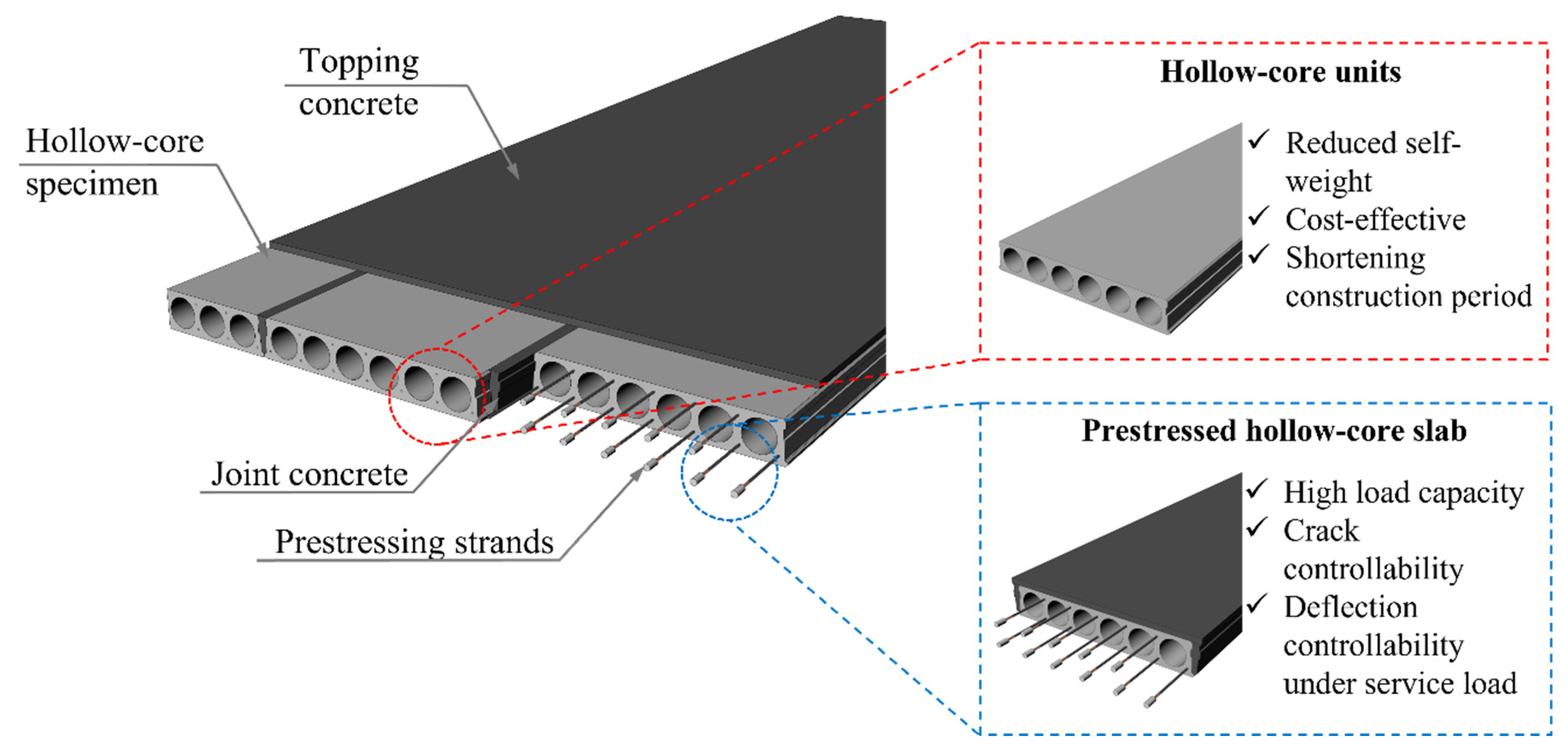
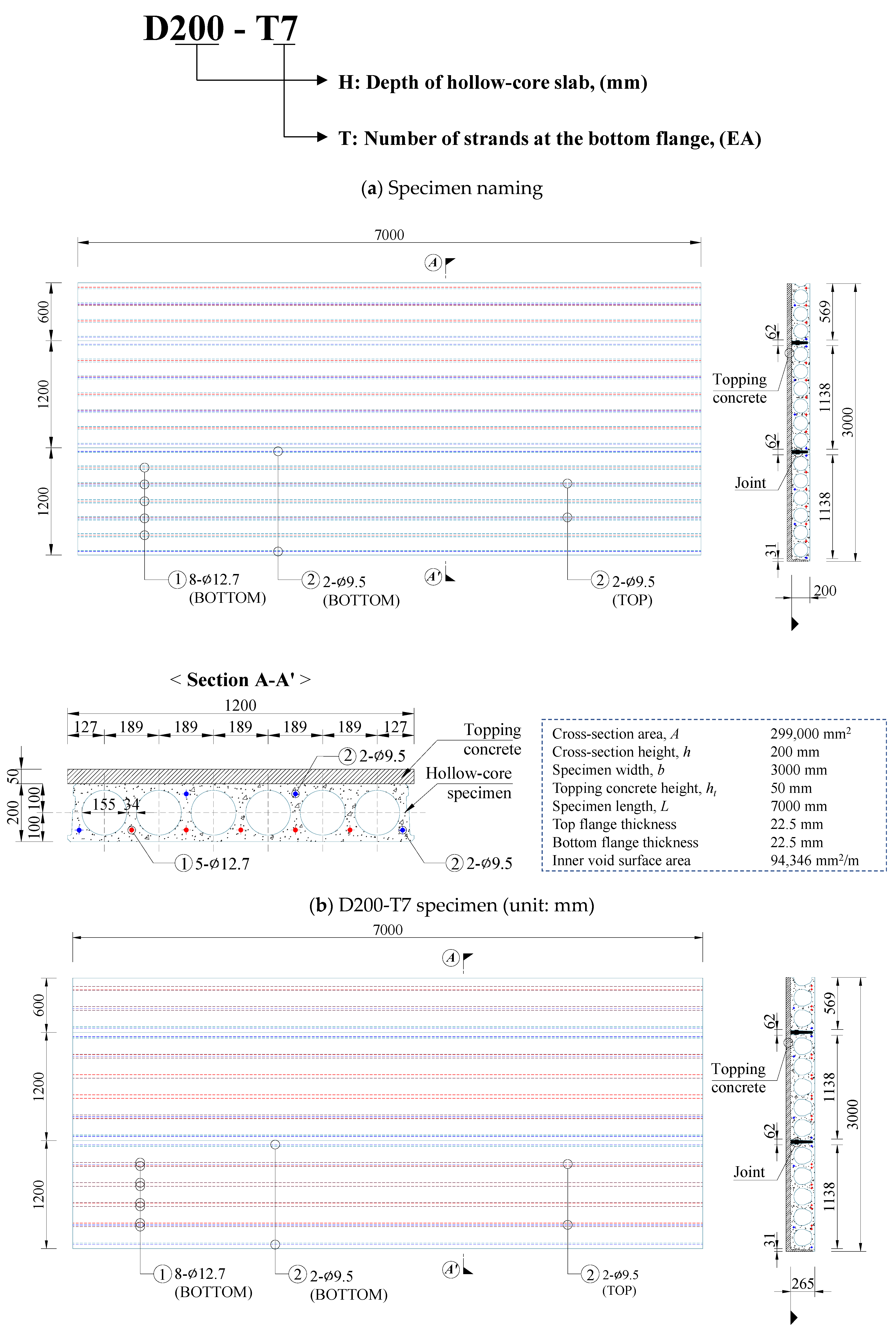
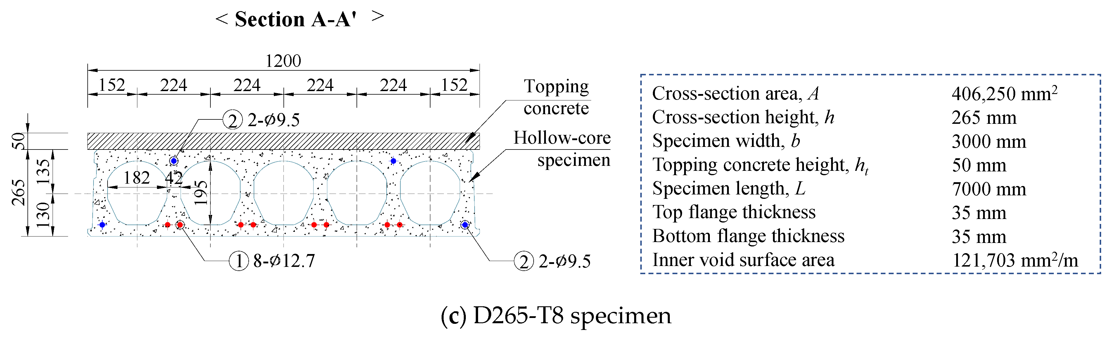
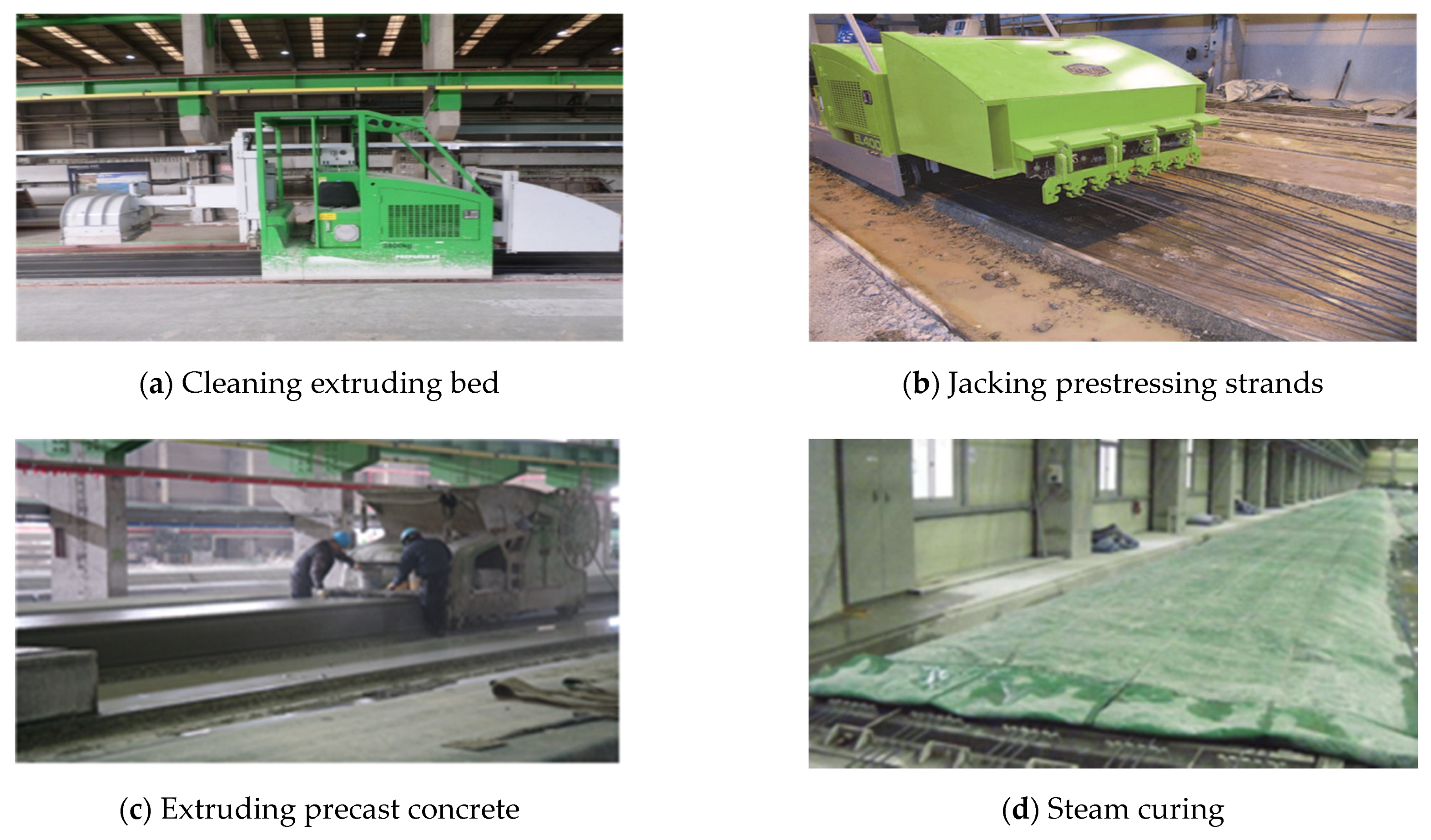
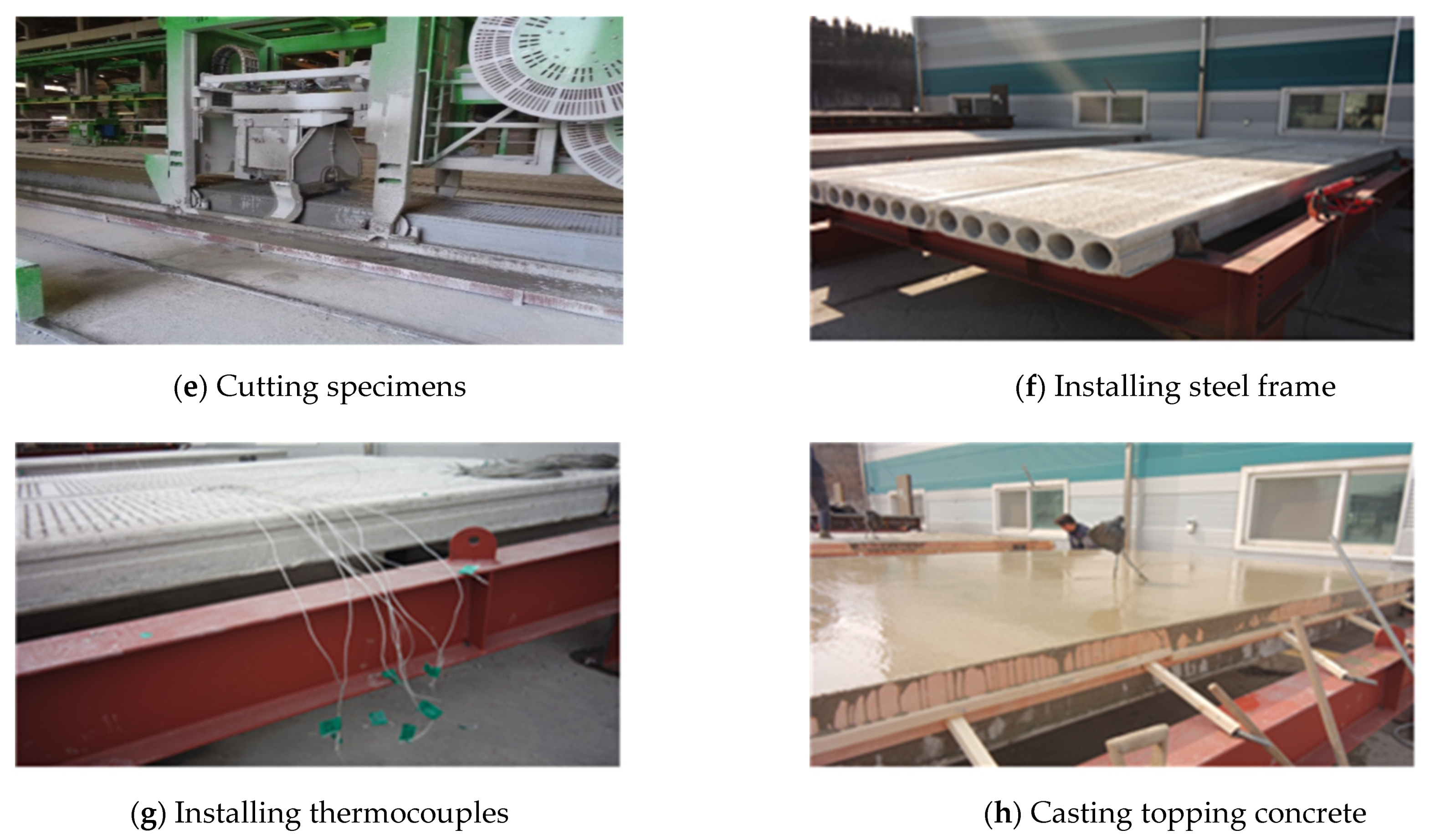
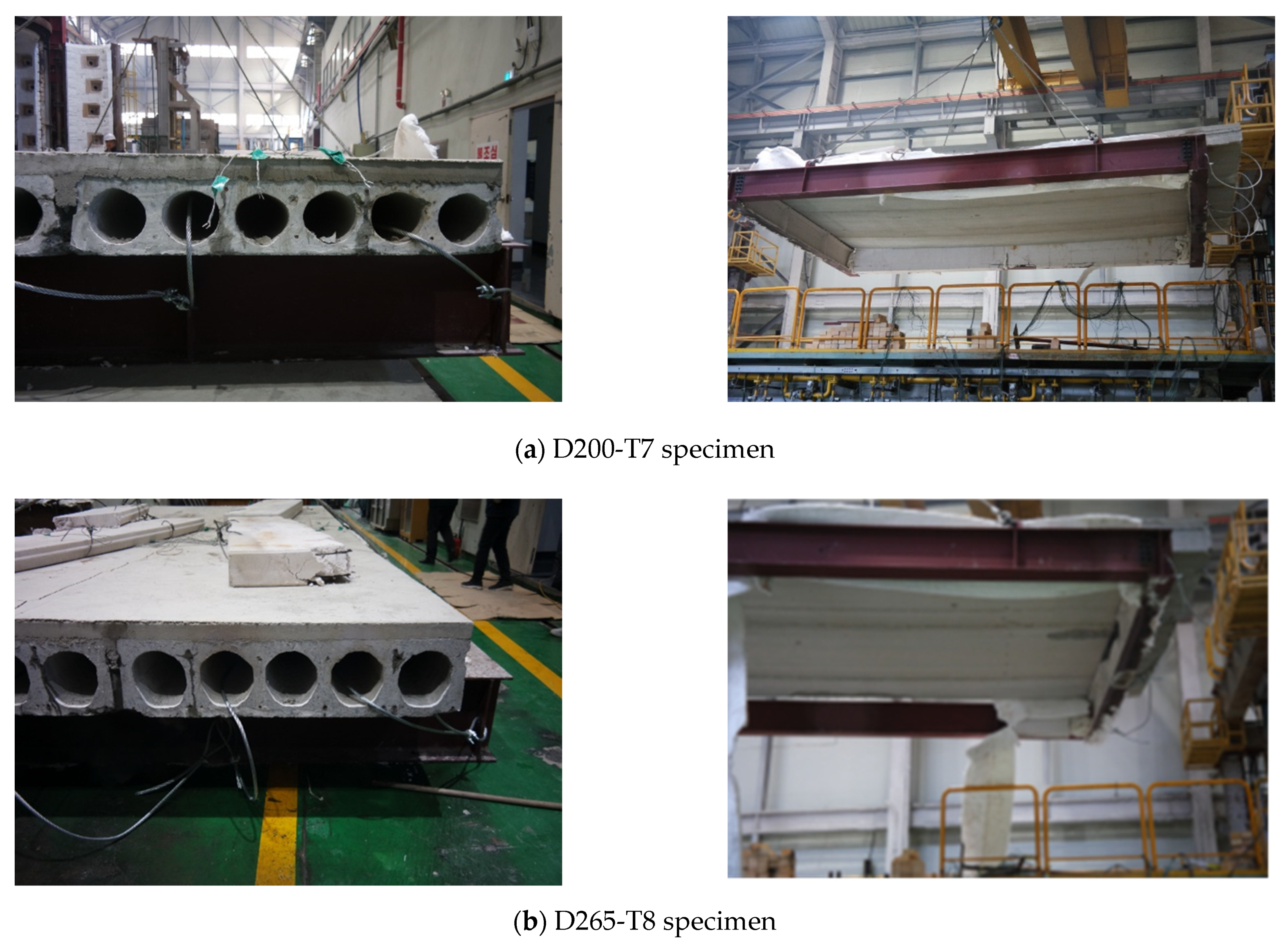
2.1. Test Specimens

Table 1 and Figure 2 show the section details and material properties of the HCS specimens. In this study, two HCS specimens with cross-sectional heights of 200 and 265 mm were fabricated, and the specimen names are shown in Figure 2a. The total length and clear span of the specimen were 7.0 and 6.0 m, respectively. Considering the furnace condition, 2.5 HCS units with a width of 1.2 m were continuously placed for each specimen to achieve a width ( b ) of 3 m. As shown in Figure 2b, the D200-T7 specimen was manufactured by pouring topping concrete with a thickness of 50 mm on the upper part of the HCS unit with a height of 200 mm. Two 9.5-mm-diameter prestressing strands were placed on the top flange of the HCS unit, whereas two 9.5-mm-diameter and five 12.7-mm-diameter strands were placed at the bottom flange. In addition, a live load of 1.5 kN/m2 was applied to the upper part of the slab during the fire test. As shown in Figure 2c, the D265-T8 specimen was fabricated by pouring topping concrete with a thickness of 50 mm on the upper part of the HCS unit with a height of 265 mm. In the D265-T8 specimen, two 9.5-mm-diameter prestressing strands were placed on the top flange of the HCS unit, whereas two 9.5-mm-diameter and six 12.7-mm-diameter strands were placed at the bottom flange. The live load of the D265-T8 specimen was set to 3.0 kN/m2.
The nominal tensile strength ( f p u ) of the prestressing strands was 1860 MPa, and the effective prestress of the strands was 0.65   f p u . The HCS unit was manufactured using an extrusion method [33]. Figure 3 shows the manufacturing process of the test specimens. The prestressing strands were first tensioned on a long-line prestress bed and then anchored at both ends of the bed. Subsequently, a machine compacted concrete simultaneously with extruding concrete with a zero slump. The slab was subjected to steam curing for 24 h and then cut to produce an HCS unit member. As described above, 2.5 HCS units with a width of 1.2 m were placed continuously (see Figure 3f), and a hole was drilled in the upper surface of the slab. Thermocouples were then installed to measure the temperature distribution in the cross-section. The specimen manufacturing process was completed by casting topping concrete. The specimens were air-cured at room temperature for 28 days, and the concrete compressive strength ( f c , P C ) of the HCS unit measured prior to the experiment was 58 MPa.

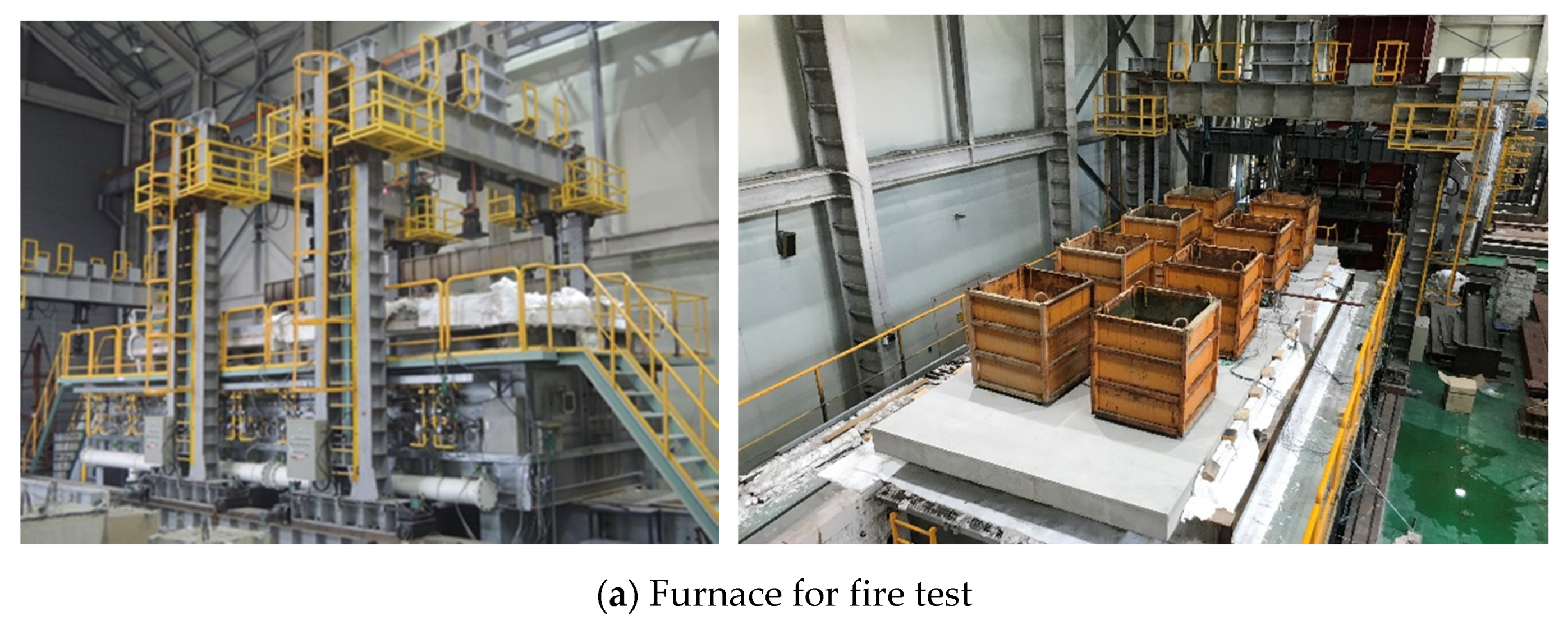
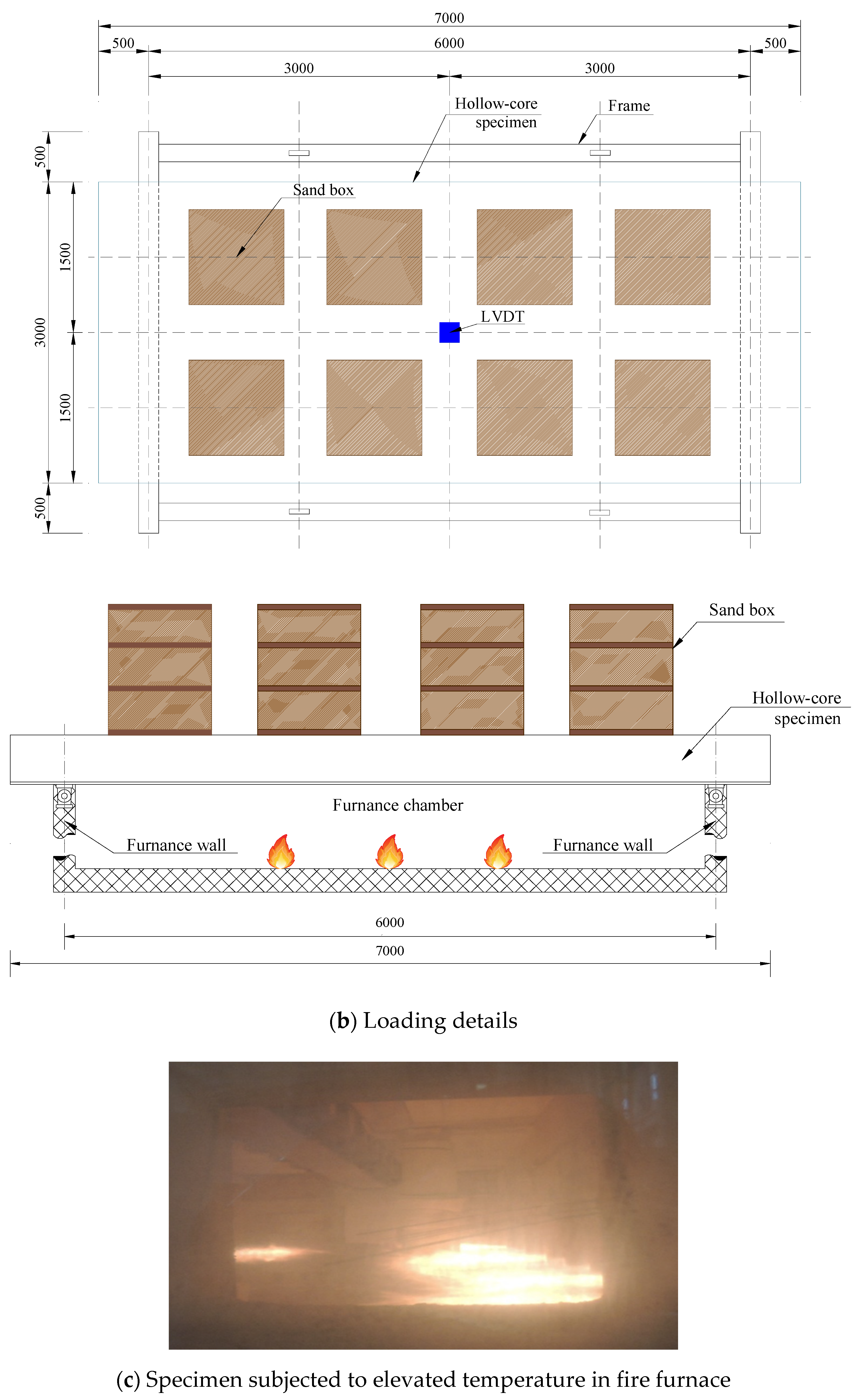
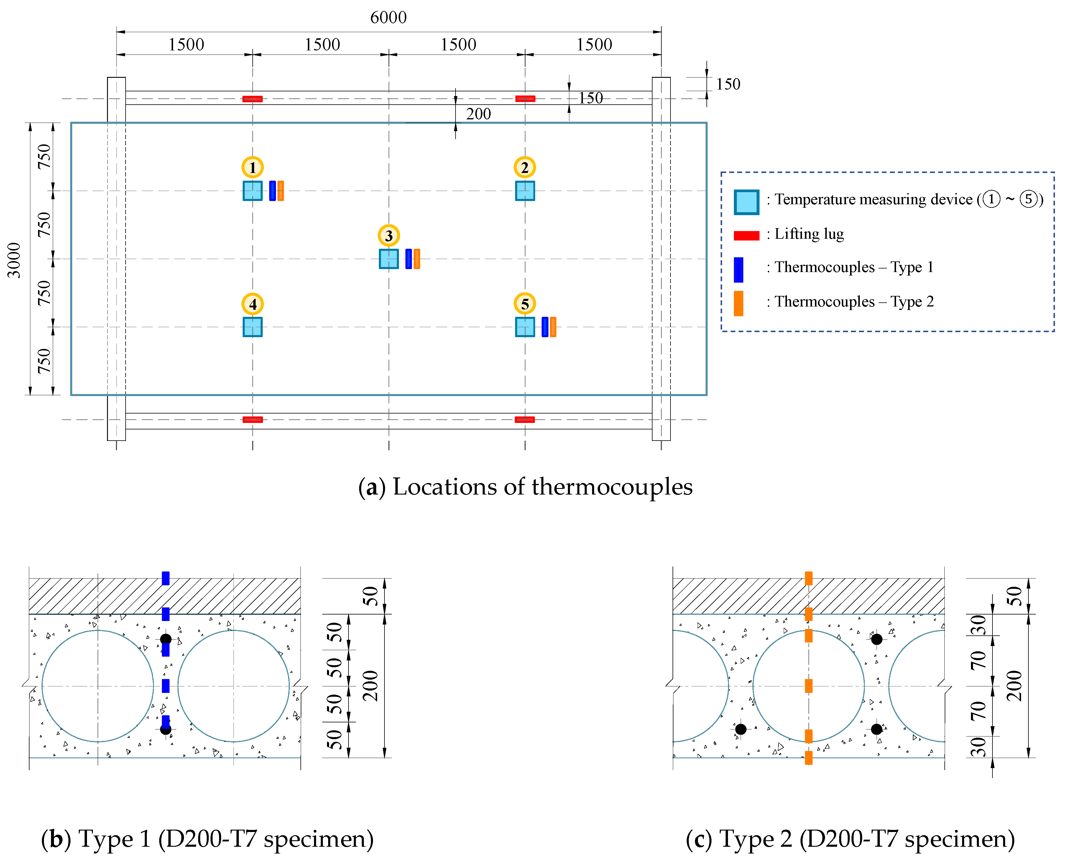
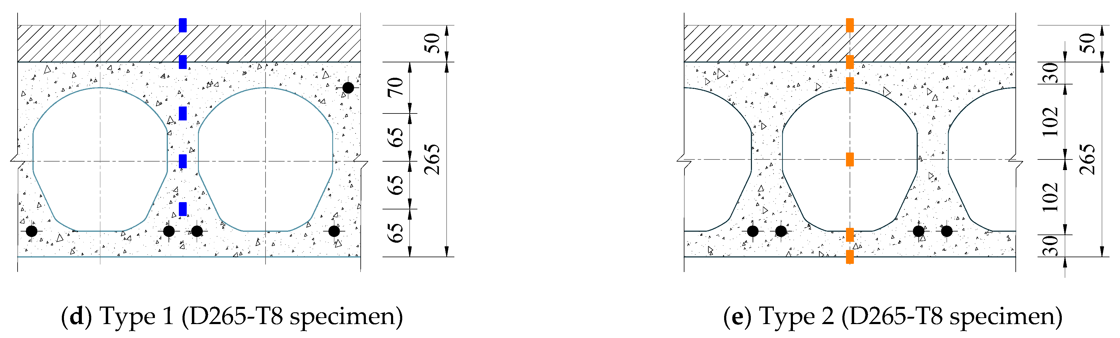
2.2. Test Apparatus and Measurements

Figure 4a shows a large fire testing furnace at the Korea Institute of Civil Engineering and Building Technology. In this study, the fire resistance test was performed by setting the clear span of the specimen, i.e., the span exposed to fire, to 6.0 m, and eight sand boxes were placed at equal intervals on the upper surface of the slab to apply the target live load evenly, as shown in Figure 4b,c. For the D200-T7 specimen, the weight of each sand box was 337.5 kg; therefore, a load of 2700 kg (=1.5 kN/m2) was applied to the specimen. For the D265-T8 specimen, the weight of each sand box was set to 675 kg, and the total load applied to the specimen was 5400 kg (=3.0 kN/m2). The temperature inside the furnace during the fire test was controlled to adhere to the ISO 834-1 standard fire curve [32], as shown in Figure 5. In the center of the upper surface of the HCS specimen, a linear variable differential transformer (LVDT) was installed in the vertical direction to measure the deflection of the specimen subjected to fire loads.
As shown in Figure 6a, the temperature change in the upper surface of the specimen was measured at five locations. In addition, as shown in Figure 6b–e, thermocouples were installed in the hollow sections and webs of the HCS specimens to measure the temperature distribution in the cross-section according to the fire exposure time.

2.3. Criteria for Evaluating Fire Resistance Performance

ISO 834-1 [32] specifies three performance criteria (i.e., integrity, insulation, and load-bearing capacity) for structural members subjected to fire loads. Integrity is defined as the ability of a structural member to prevent a flame from penetrating, and it is evaluated based on the time of ignition of a cotton pad, penetration of a gap gauge, or sustained flaming on the unexposed surface. Insulation refers to the ability of the test specimen to prevent heat penetration; if the increase in temperature of the unheated surface exceeds the average 140 K or the maximum 180 K compared with the initial temperature during the fire test, then the member is regarded as not fulfilling the insulation criterion. In addition, the load-bearing capacity criterion for horizontal members under fire loading was defined for the vertical deflection ( D ) and the rate of deflection ( d D / d t ), respectively, as follows:
D = L 2 400 d   ( mm )
d D d t = L 2 9000 d   ( mm / min )
where L is the length of the clear span, and d is the height of the section. However, it is noteworthy that Equation (2) is applied only when the vertical deformation of the member exceeds L / 30 (mm). The maximum allowable deformation and strain limit calculated using Equations (1) and (2) were 360.0 mm and 16.0 mm/min, respectively, for the D200-T7 specimen, whereas they were 285.7 mm and 12.7 mm/min, respectively, for the D265-T8 specimen.

3. Experimental Results

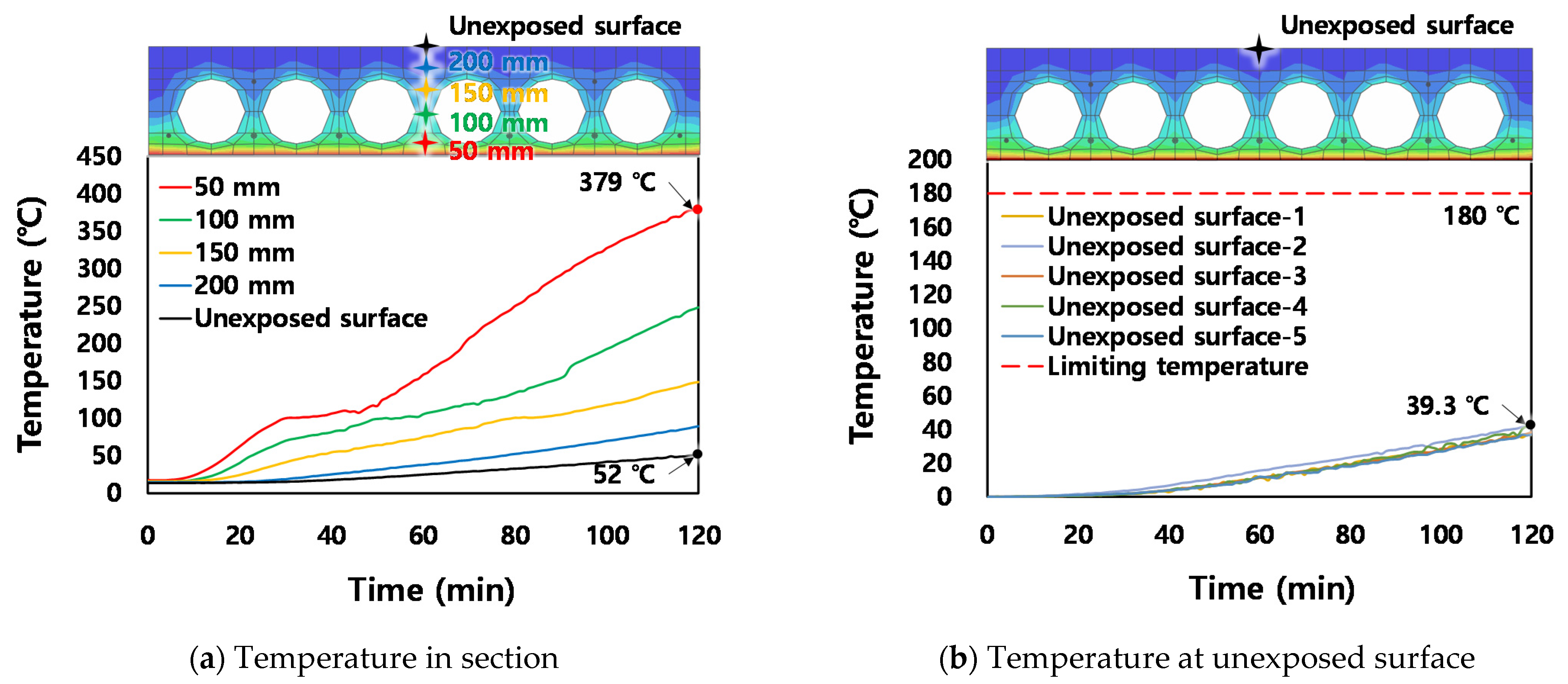
3.1. Thermal Behaviors of Test Specimens

In this study, a fire load was applied to the lower surface of the test specimens for 120 min (=7200 s); the two specimens satisfied the integrity criterion because no flame penetration was observed during the test. Figure 7 and Figure 8 show the temperature distribution in the section and the temperature at the upper surface of the slab with respect to the fire exposure time. In the D200-T7 specimen, when the fire resistance time reached 120 min, the maximum temperature of concrete around the prestressing strands was approximately 379 °C, as shown in Figure 7a. The upper surface of the slab indicated an extremely low increase in temperature, i.e., an average of 39.3 K and a maximum of 42.5 K, as shown in Figure 7b. Figure 8 shows the temperature behavior of the D265-T8 specimen. The maximum temperature of concrete around the strands was approximately 345 °C; similar to the D200-T7 specimen, the increase in temperature at the top of the slab was extremely low (i.e., an average of 28.8 K and a maximum of 33.3 K).
In general, the temperature of the D265-T8 specimen was lower than that of the D200-T7 specimen. This is because the inner void surface area of the D265-T8 specimen was larger than that of the D200-T7 specimen; hence, the heat release rate was relatively high [27]. In addition, it was estimated that the relatively large heat capacity of the D265-T8 specimen contributed to a slow temperature increase at the top of the section. Consequently, the two specimens satisfied both the insulation and integrity criteria presented in ISO834-1 [32] until the end of the experiment.

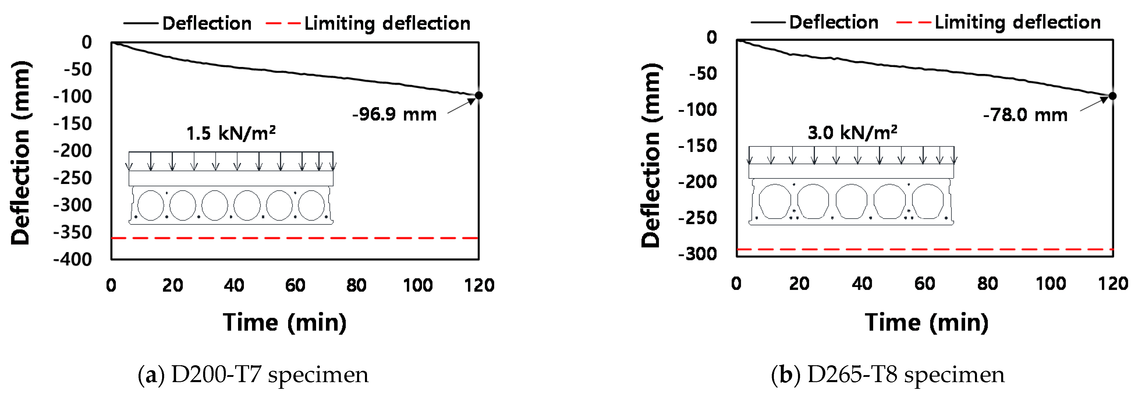
3.2. Deflection Responses According to Fire Exposure Time

Figure 9 shows the vertical deflection of the HCS specimens according to the fire exposure time. As shown in Figure 9a, the deflection of the D200-T7 specimen indicated a constant increase according to the fire exposure time, and a deflection of 97.2 mm occurred at 120 min (=7200 s). As shown in Figure 9b, the maximum deflection of the D265-T8 specimen was 76.7 mm. Considering that the maximum allowable deformation of the D200-T7 specimen was 360.0 mm, and that of the D265-T8 specimen was 285.7 mm, the deflection generated in both specimens was approximately 27% of the limit deflection, which suggests that HCS specimens have superior fire resistance performance.
Figure 10 shows the HCS specimens observed after the fire resistance test. In both the D200-T7 and D265-T8 specimens, concrete spalling was observed on the lower part of the member exposed directly to the flame. It was speculated that the spalling was caused by the movement of free water in the concrete and moisture generated from the dehydration reaction [34]. However, because spalling occurred only in an extremely small area of the entire surface of the slab, deflection did not increase significantly during the test.

4. Nonlinear Finite Element Analysis Considering Fire Damage

Based on the experimental results reported in the previous section, a nonlinear FE analysis was performed using the general-purpose FE program ABAQUS/CAE [35], and the rationality of the presented modeling technique was verified by comparing the analysis results with the test results. In addition, a parametric analysis was performed using the verified FE model, in which the HCS depth, span length, hollow ratio in a section, cover thickness of concrete, and load ratio were set as variables, and the fire resistance performance of the HCS according to each key variable was investigated in detail.

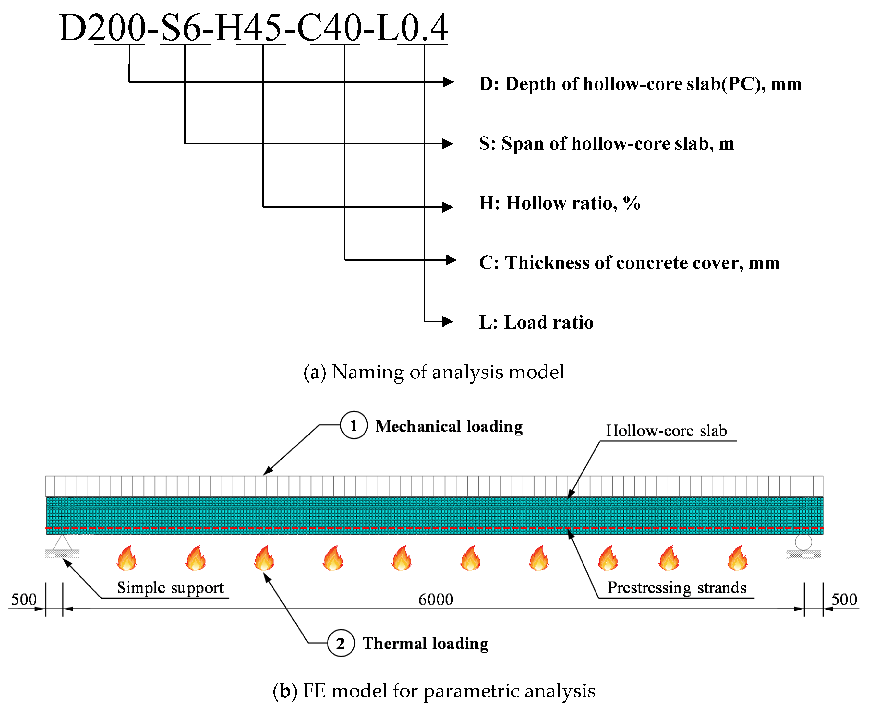
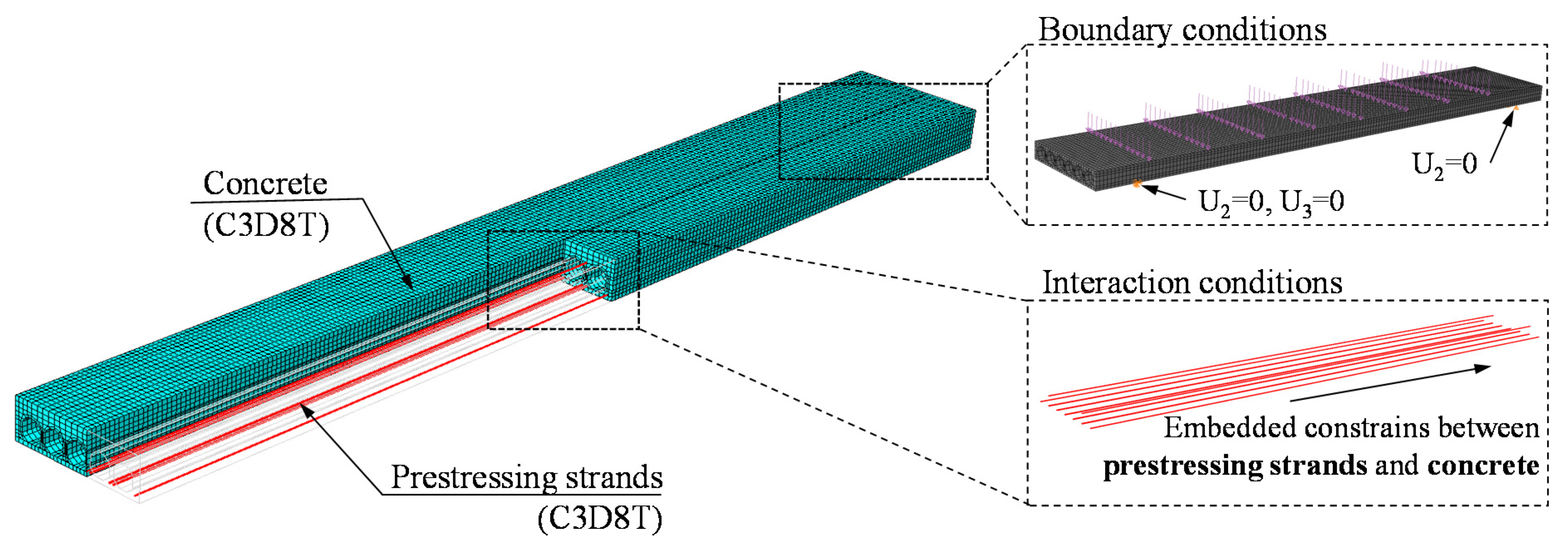
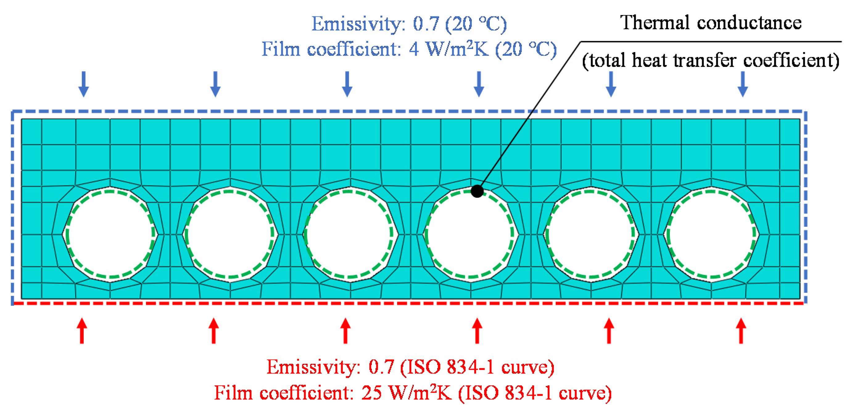
4.1. Details of FE Models

Table 2 and Figure 11 show the details of the members modeled for the FE analysis. In the slab model name, the number after “D” indicates the HCS depth, the number after “S” the span length (mm), the number after “H” the hollow ratio of the section (%), the number after “C” the cover thickness of concrete (mm), and the number after “L” the load ratio. For example, D200-S6-H45-C40-L0.4 is a member in which a load corresponding to 40% of the ultimate load is applied to the HCS unit with a depth of 200 mm, a span length of 6 m, a 45% hollow ratio, and a cover thickness of 40 mm. It should also be noted that D200-S6-H45-C35-L0.1 and D265-S6-H45-C35-L0.1 members were used to verify the accuracy of the FE analysis based on a comparison with the fire resistance test performed in this study. Figure 11b shows that in the FE analysis, a load was applied to the slab, and then a temperature load was applied in the same manner as the actual fire resistance test.
As shown in Figure 12, concrete, prestressing strands, and reinforcing bars were modeled using a coupled temperature-displacement element (C3D8T) that enables the heat transfer analysis and structural analysis simultaneously. In the analysis model, the interaction conditions between concrete and prestressing strands or reinforcing bars were assumed to be fully bonded, which was modeled by the embedded option. In the specimens fabricated in this study, the reinforcing bars were not placed in the topping concrete with a thickness of 50 mm. Accordingly, the D200-S6-H45-C35-L0.1 and D265-S6-H45-C35-L0.1 members were modeled to have the same details of topping concrete, whose purpose was to verify the accuracy of the FE analysis. Both ends of the member were modeled as simply supported, which is the same as the actual experimental test condition. In addition, an uniformly distributed load was applied to the top of the slab via the pressure option in ABAQUS/CAE. Static simulations allowing for nonlinearity arising from both the constitutive law and the large geometric deformations were performed. The convergence criteria have been set as the default convergence criteria provided by Abaqus, i.e., 0.5% of the force acting on the structure over time.
Figure 13 shows the thermal boundary conditions of the analysis model. The temperature of the standard fire curve specified in ISO834-1, shown in Figure 5, was applied to the bottom of the HCS unit. Here, an emissivity factor of 0.7 and a film coefficient of 25 W/m2K were applied, based on Eurocode 1 and 2 [31,36]. Room temperature (=20 °C) was applied to the top and side surfaces of the slab, which were not directly exposed to fire, and an emissivity factor of 0.7 and a film coefficient of 4 W/m2K were applied in this case. The thermal conductance option was used to implement heat transfer in the hollow-core section.

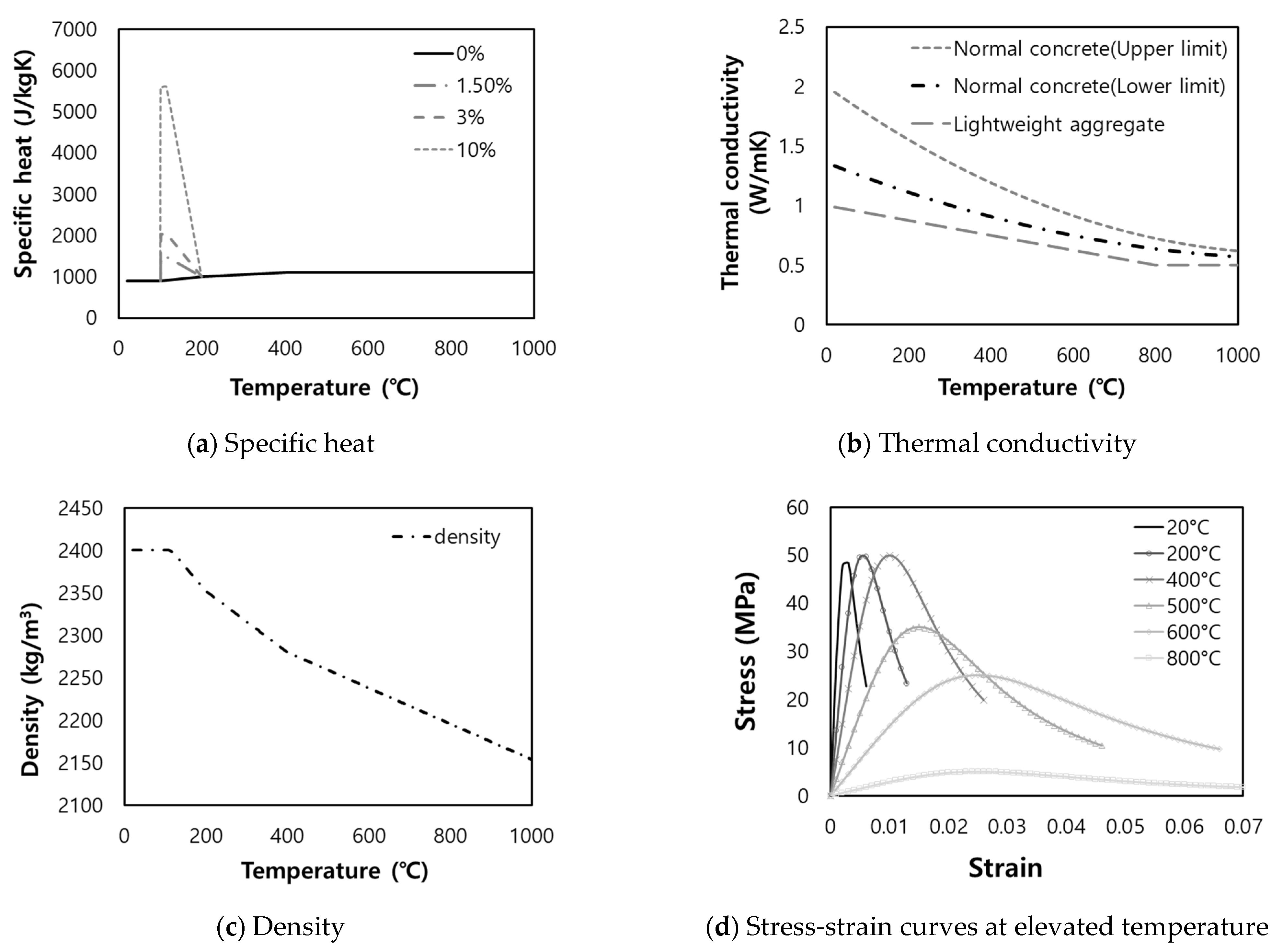
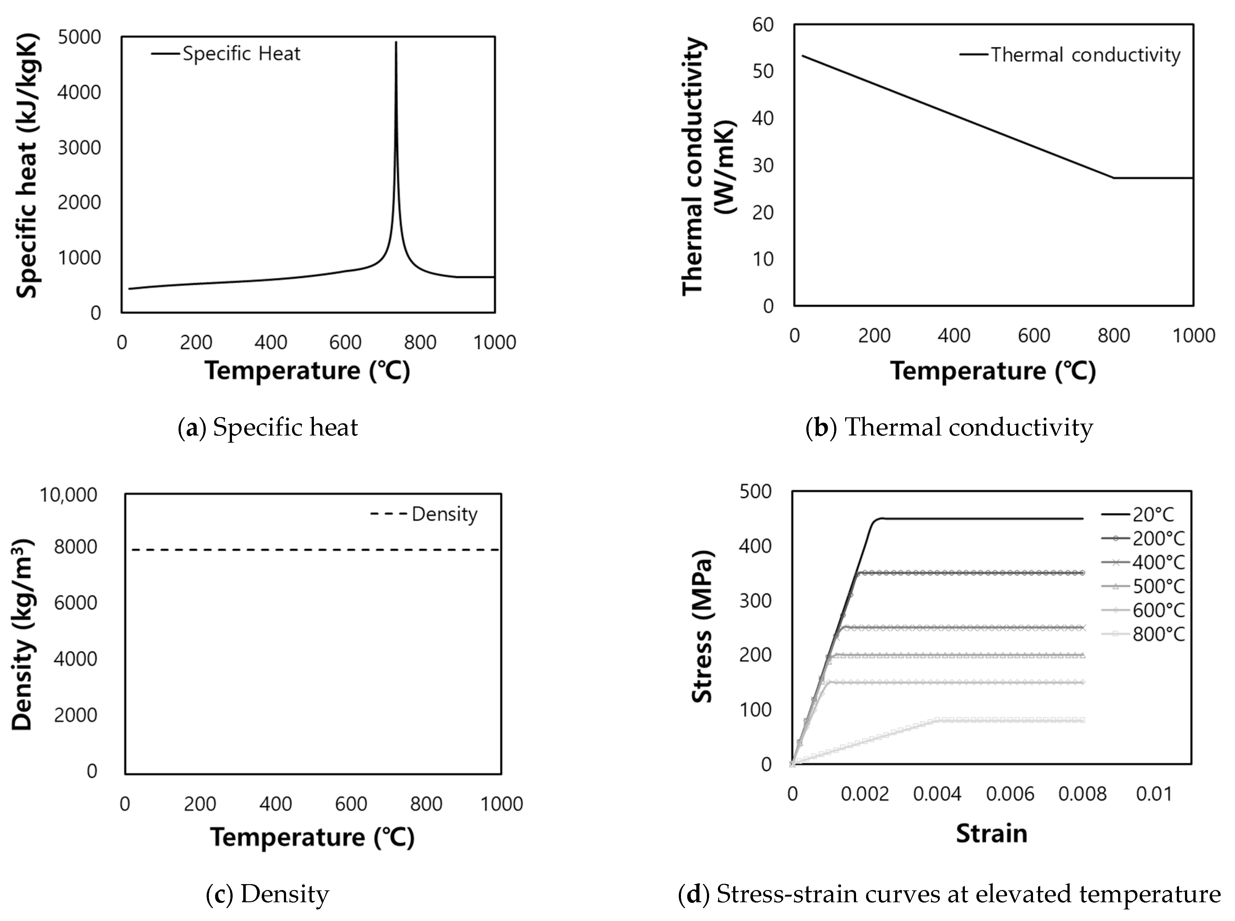
4.2. Material Properties

The material properties presented in Table 1 were applied to the slabs modeled for the verification of the FE analysis (i.e., D200-S6-H45-C35-L0.1 and D265-S6-H45-C35-L0.1 members), whereas the elastic modulus of the prestressing strands of 200 GPa, tensile strength of prestressing strands ( f p u ) of 1860 MPa, and compressive strength of concrete ( f c ) of 50 MPa were applied to other slab members. In addition, the concrete damaged plasticity model [37] was used as a yield criterion, the bilinear model (i.e., the elasto-linear hardening model) [31] for the stress–strain relationships of the prestressing strands, and the Popovics model [38] for the constitutive law of concrete.
The thermal and mechanical properties of concrete and steel materials change as temperature increases. The thermal properties of materials include thermal conductivity, specific heat, and emissivity factor, whereas the mechanical properties include density, Poisson’s ratio, and stress–strain relationship. As shown in Figure 14 and Figure 15, the thermal and mechanical properties of concrete and steel materials presented in Eurocode 4 Part 1-2 [39] were applied in this study.

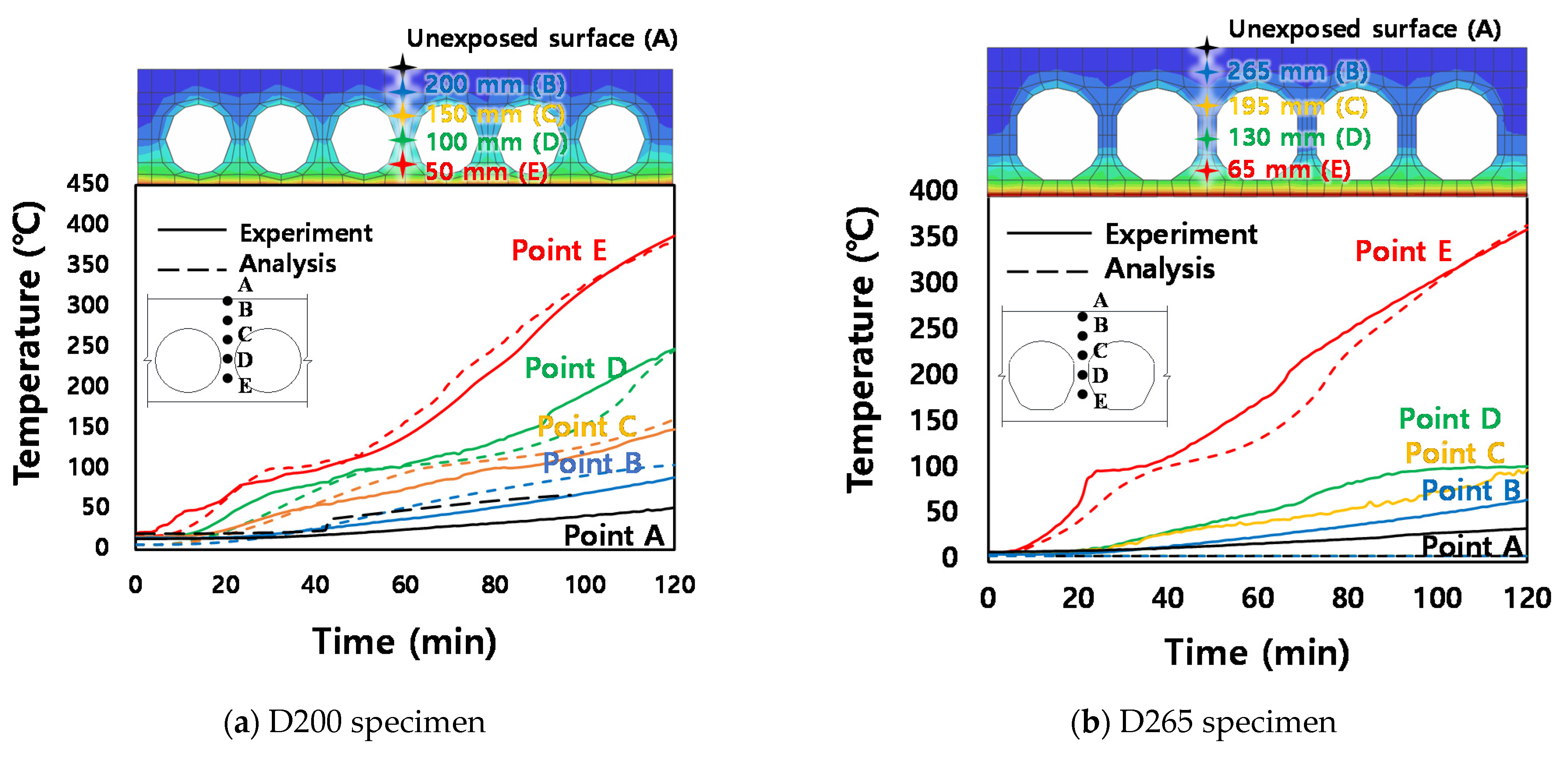
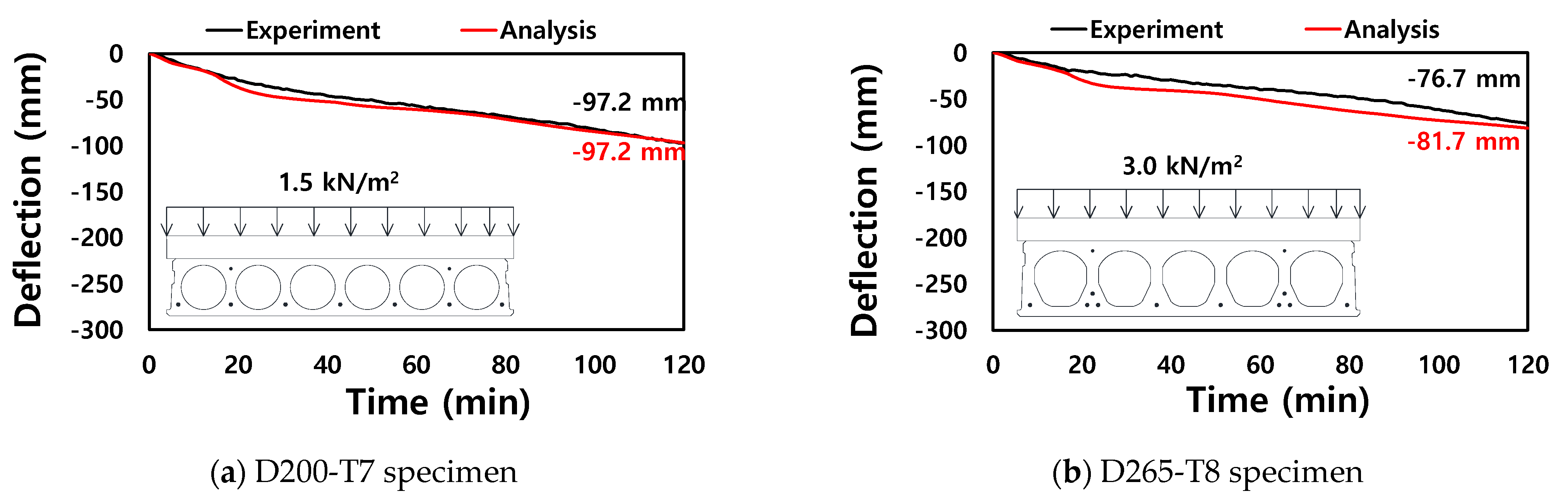
4.3. Validation of FE Model

Figure 16 and Figure 17 as well as Table 3 present a comparison of the test and analysis results in terms of temperature in the cross-section and mid-span deflection of the D200-T7 and D265-T8 specimens. It was found that the FE model evaluated the temperature for each cross-sectional height according to the fire exposure time with good accuracy. Furthermore, it predicted the maximum temperature of concrete around the prestressing strands located at the bottom flange when the fire resistance time reached 120 min (=7200 s), which was similar to the test results. In addition, as shown in Figure 17a, the FE model yielded analysis results that were similar to the deflections caused by the fire load on the D200-T7 specimen, and the difference between the deflections obtained from the analysis and test was only 0.03 mm when the fire resistance time reached 120 min. As shown in Figure 17b, for the D265-T8 specimen, the FE model simulated the fire resistance behavior of the specimen accurately, and the final deflection predicted by the FE model was approximately 81.7 mm, which is similar to the deflection observed in the test (76.7 mm).
Meanwhile, to investigate the fire resistance performance of HCSs more comprehensively, many fire tests are to be conducted while considering various cross-sectional details, load conditions, and span lengths. However, this is difficult to achieve when the complexity of the experiment and the time and costs required for the fire test are considered. Therefore, in this study, numerical simulations were performed using the verified FE model, where the HCS depth, span length, hollow ratio in a section, cover thickness of concrete, and load ratio were used as variables for 21 cases (see Table 2). Subsequently, the fire resistance performance of the HCS according to the key variables was analyzed in detail.

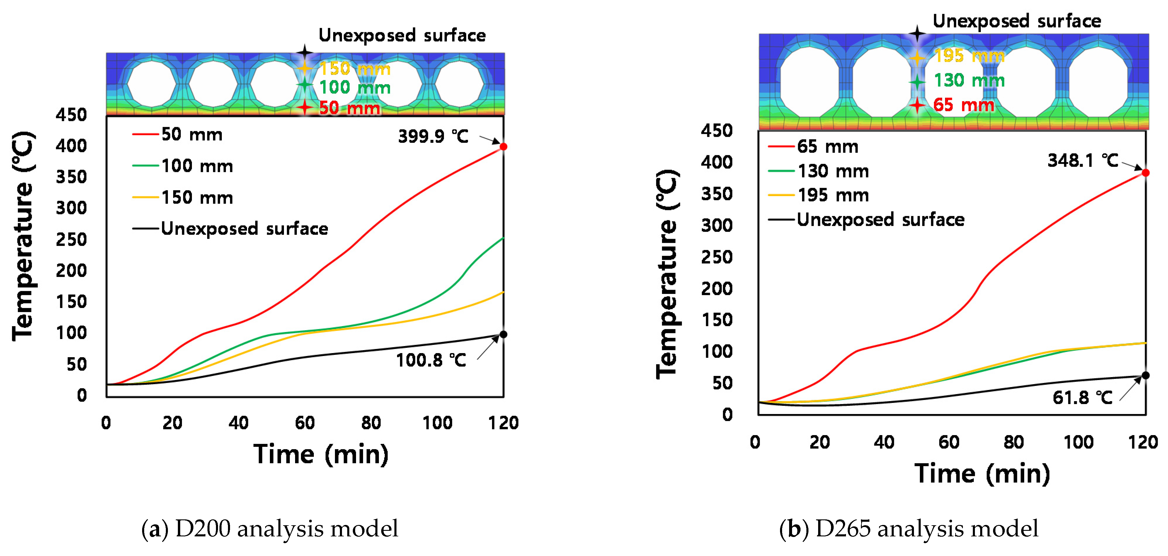
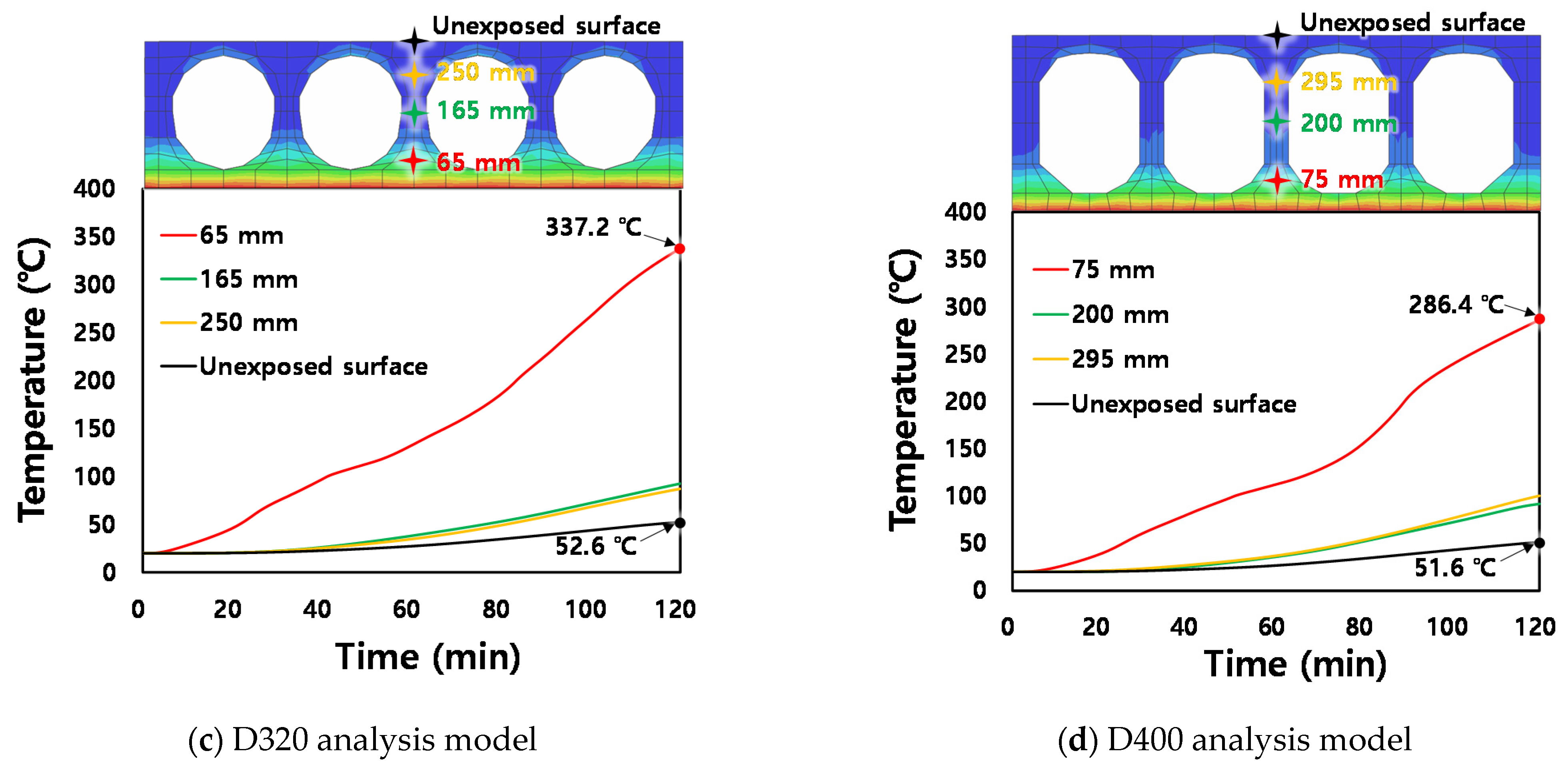
4.4. Parametric Analysis Results of Thermal Responses

In this study, the analysis was conducted until the fire exposure time reached 120 min. Figure 18 shows the temperature distribution in the cross-section with respect to the fire exposure time for each HCS depth (i.e., 200, 265, 320, and 400 mm). The maximum temperatures of concrete around the prestressing strands of the D200, D265, D320, and D400 series were 399.9 °C, 348.1 °C, 337.2 °C, and 286.4 °C, and the temperatures at the upper surface of the slab were 100.8 °C, 61.8 °C, 52.6 °C, and 51.6 °C, respectively. This indicates that the temperature increase in the section decreased as the HCS depth increased. This is because relatively rapid heat release occurred as the surface area of voids in the section increased with the depth, and the heat capacity of the member increased with the cross-sectional area. [27] Consequently, all of the D200, D265, D320, and D400 series satisfied the insulation criterion presented in ISO834-1 [32] until the fire exposure time of 120 min.

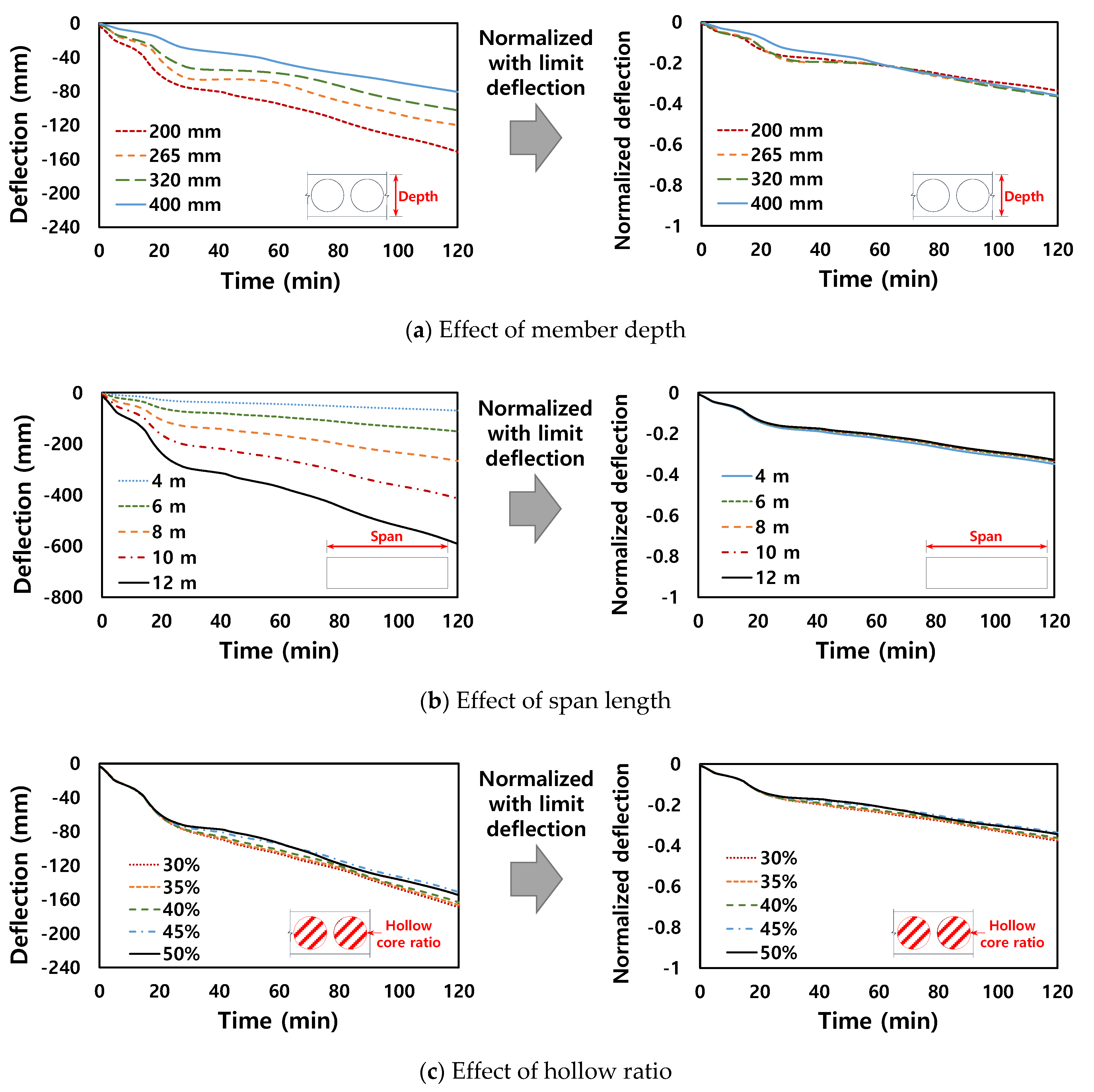
4.5. Parametric Analysis Results of Deflections

Figure 19 shows the vertical deflections of the HCS according to the fire exposure time for each variable (i.e., HCS depth, span length, hollow ratio in a section, cover thickness of concrete, and load ratio). As shown in Figure 19a, the deflection tended to decreased as the HCS depth increased. This is because the heat transfer rate within the cross-section decreased as the heat capacity of the HCS section increased at the same time when the flexural stiffness of the section increased significantly as the depth increased. When the heat transfer rate in the section decreased, the mechanical properties of the concrete and prestressing strands deteriorated relatively slowly, as shown in Figure 14 and Figure 15. In addition, the deflection showed a tendency to increase significantly with the span length, as shown in Figure 19b. However, when the vertical deflection of the HCS was normalized with the limit deflection calculated using Equation (1), similar values were obtained regardless of the HCS depth and span length. This is because the limit deflection calculation formula presented in ISO 834-1 [32] considers the section depth and span length reasonably.
As shown in Figure 19c, the vertical deflection of the HCS decreased slightly as the hollow ratio in the section increased. This is because within the hollow ratio range of 30–50%, heat release occurred relatively rapidly as the surface area inside the void increased with the hollow ratio. In addition, as shown in Figure 19d, it appeared that as the cover thickness of concrete increased, the deflection increased because the effective depth of the prestressing strands decreased with increasing the cover thickness of concrete at the same height of the section. However, the effects of the hollow ratio in a section and the cover thickness of concrete on the deflection of the HCS under fire were insignificant when the hollow ratio was 35 to 50% and the cover thickness of concrete was 30 to 50 mm, which are applied widely in practice.
Figure 19e shows the deflection of the HCS according to the fire exposure time for each load ratio (i.e., the ratio of the external load to the ultimate load). It was discovered that the load ratio exerted a dominant effect on the deflection of the HCS compared with any other variables. As the load ratio increased, the neutral axis in the cross-section moved up due to flexural cracks, resulting in a decrease in flexural stiffness of the section. Therefore, the vertical deflection normalized to the limit deflection increased proportionally with increasing the load ratio.
In summary, within the range of variables examined in this study (i.e., depth of 200–400 mm, hollow ratio of 30–50%, etc.), the effects of the HCS depth, span length, hollow ratio in a section, and cover thickness of concrete on the vertical deflection of the HCS were slight in comparison with the limit deflection (i.e., normalized deflection). Furthermore, it was confirmed that the load ratio exerted the most significant effect on the deflection of the HCS under fire.

5. Conclusions

In this study, experimental and analytical research was conducted to investigate the fire resistance performance of HCSs. Two HCS specimens were fabricated, where the cross-sectional depth was set as a variable. The temperature distribution in the section and the deflection of the member according to the fire exposure time were measured and analyzed comprehensively. An FE analysis was conducted on the HCS under fire, and the rationality of the FE model was verified via comparison with the test results. In addition, the HCS depth, span length, hollow ratio in a section, cover thickness of concrete, and load ratio were set as key variables to perform the parametric analysis. The fire resistance performance of the HCS was then evaluated according to each variable. The conclusions obtained from this study are as follows:
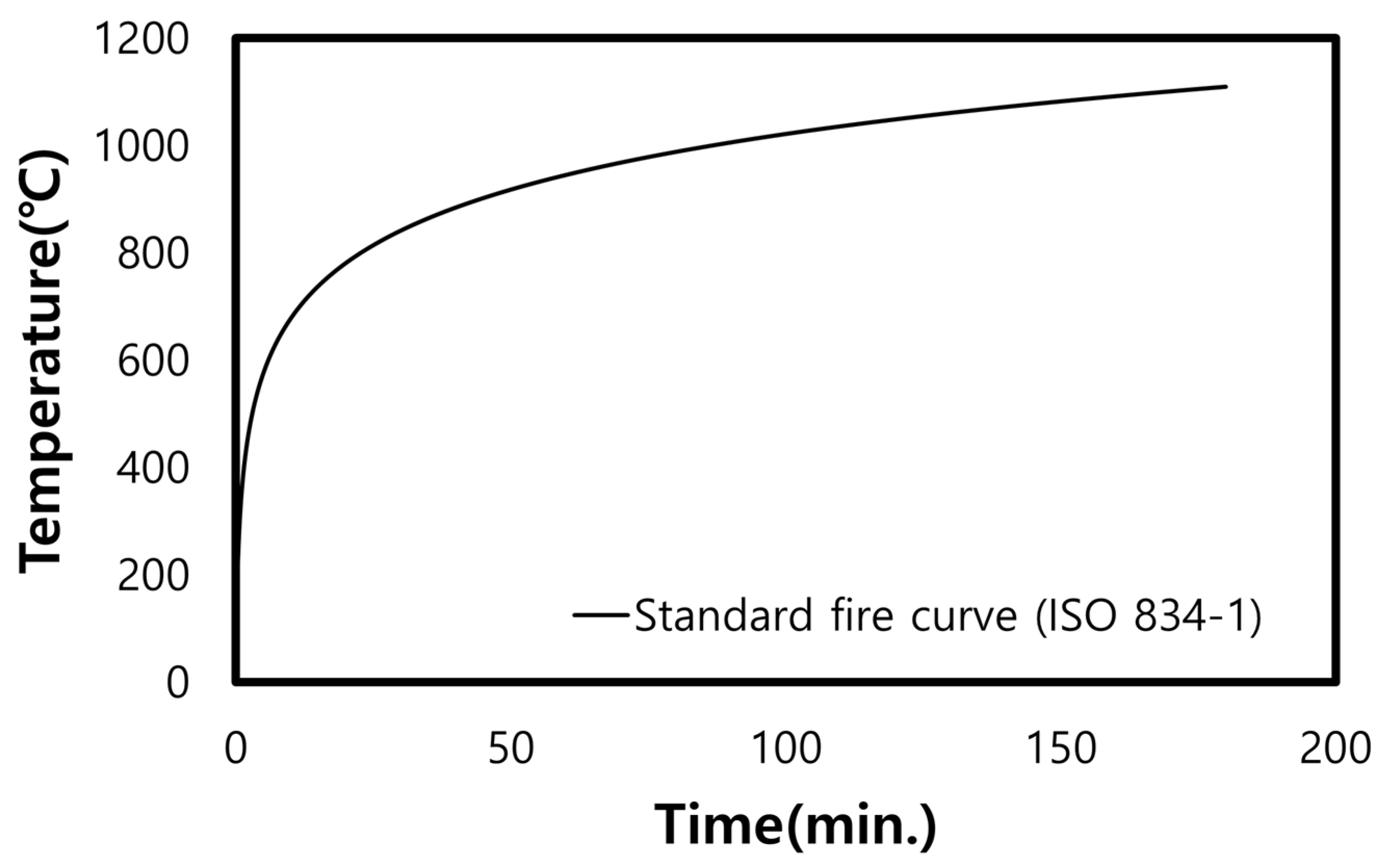
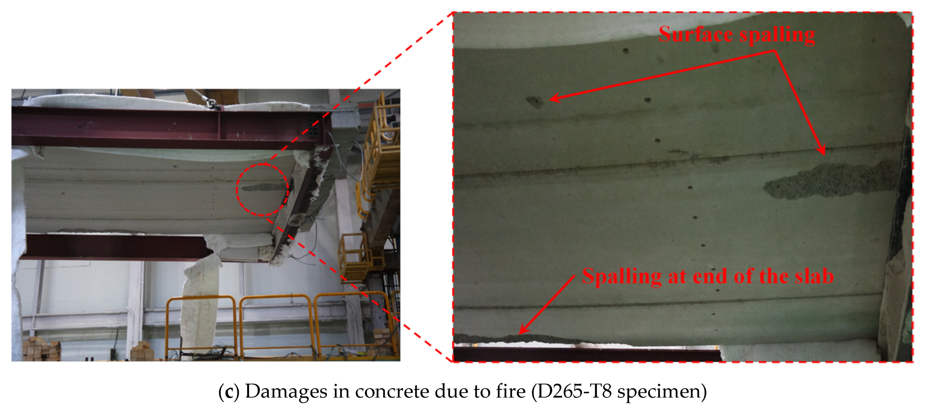
  • In 2 h of fire exposure, the temperature increase in the upper part (i.e., unexposed surface) of the D200-T7 and D265-T8 specimens was 42.5 K and 33.3 K, respectively, which are extremely low and correspond to 19–24% of the temperature increase limit (180 K) specified in ISO 834-1. In addition, it was confirmed that the HCS demonstrated excellent insulation and integrity performance because no flame penetration was observed in either specimen.
  • The maximum deflection that occurred in the D200-T7 and D265-T8 specimens was 97.2 and 76.7 mm, respectively, which were only approximately 27% of the deflection limit presented in ISO 834-1. Therefore, it can be concluded that the load-bearing performance of the D200-T7 and D265-T8 specimens was excellent during a fire.
  • The fire resistance performance of the HCS was evaluated via a nonlinear FE analysis, and the FE model demonstrated excellent accuracy in evaluating fire resistance behavior characteristics, such as the temperature distribution in the cross-section and the deflection of specimens with respect to the fire exposure time.
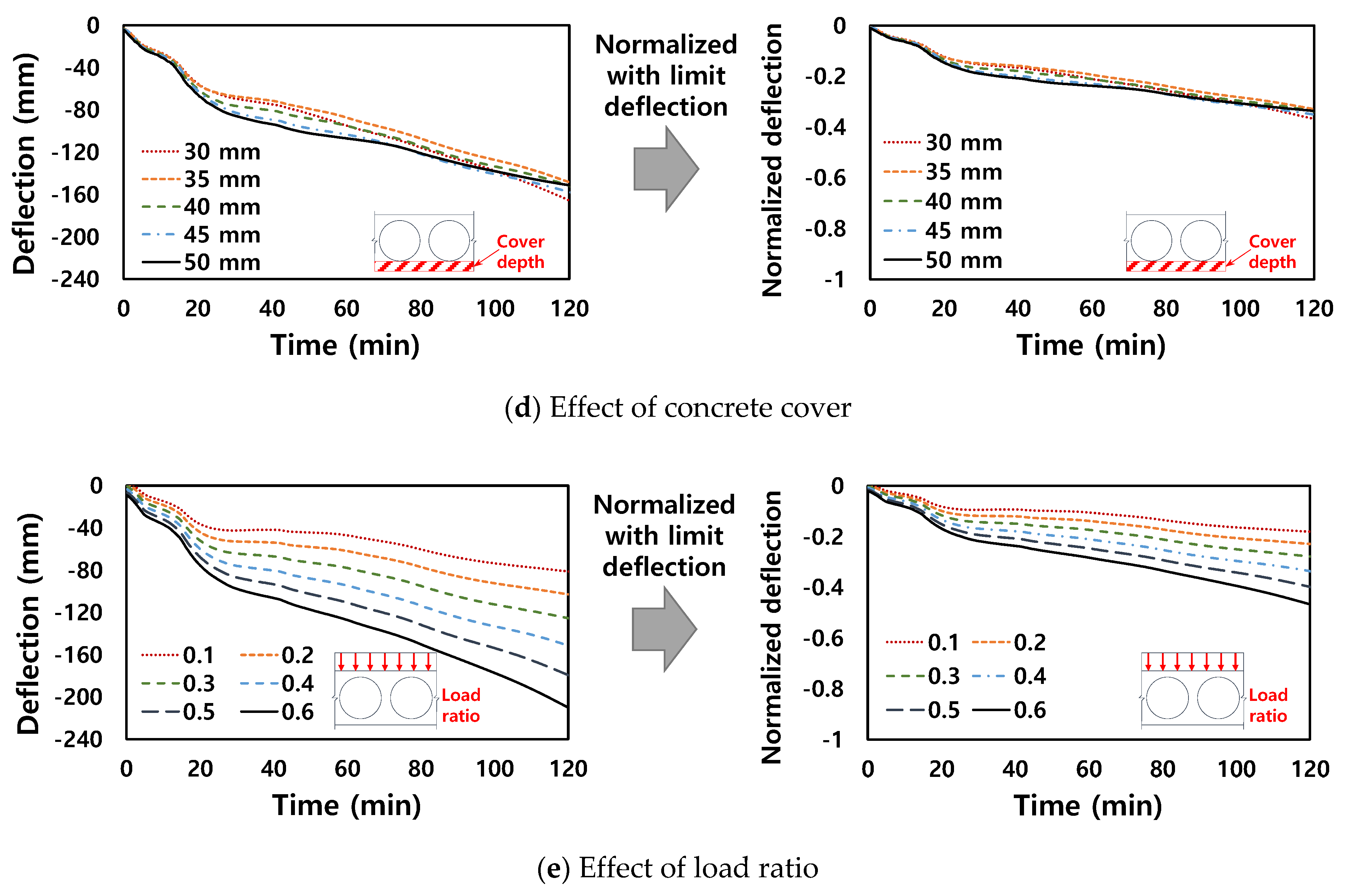
  • The results of the parametric analysis based on the verified FE model showed that the deflection tended to decrease as the depth of the HCS increased. This is because the heat transfer rate within the cross-section decreased as the heat capacity of the HCS section increased at the same time when the flexural stiffness of the section increased significantly with the depth. In addition, the deflection of the HCS increased significantly with the span length. However, when the vertical deflection of the HCS was normalized to the limit deflection presented in ISO 834-1, the normalized deflections showed similar values regardless of the HCS depth and span length. This is because the limit deflection calculation formula presented in ISO 834-1 reflects the effects of the section depth and span length reasonably.
  • Compared with other variables associated with the HCS member details, the load ratio exerted a more significant effect on the deflection of the HCS subjected to fire. As the load ratio increased, the vertical deflection normalized to the limit deflection increased proportionally. Therefore, to obtain more accurate evaluation results pertaining to the fire resistance performance of HCSs, the magnitude of the live load exerted during a fire, as well as details regarding the member should be determined appropriately.

Author Contributions

Original draft manuscript, I.H.; Validation, K.D., S.-J.H.; Investigation, S.-H.C., H.J.; Supervision and Review Writing, K.S.K. All authors have read and agreed to the published version of the manuscript.

Funding

This work was supported by the Korea Agency for Infrastructure Technology Advancement (KAIA) grant funded by the Ministry of Land, Infrastructure and Transport (Grant 21CTAP-C163892-01). Also, the sixth author, Kang Su Kim, would like to acknowledge that this research was supported by the Basic Study and Interdisciplinary R&D Foundation Fund of the University of Seoul (2021).

Institutional Review Board Statement

Not applicable.

Informed Consent Statement

Not applicable.

Data Availability Statement

The data presented in this study are available on request to the corresponding author.

Conflicts of Interest

The authors declare no conflict of interest.

References

  1. Albero, V.; Saura, H.; Hospitaler, A.; Montalvà, J.M.; Romero, M.L. Optimal design of prestressed concrete hollow core slabs taking into account its fire resistance. Adv. Eng. Softw. 2018, 122, 81–92. [Google Scholar] [CrossRef]
  2. Lee, Y.J.; Kim, H.G.; Kim, M.J.; Kim, D.H.; Kim, K.H. Shear Performance for Prestressed Concrete Hollow Core Slabs. Appl. Sci. 2020, 10, 1636. [Google Scholar] [CrossRef] [Green Version]
  3. Han, S.J.; Jeong, J.H.; Joo, H.E.; Choi, S.H.; Choi, S.; Kim, K.S. Flexural and Shear Performance of Prestressed Composite Slabs with Inverted Multi-Ribs. Appl. Sci. 2019, 9, 4946. [Google Scholar] [CrossRef] [Green Version]
  4. Ju, H.; Han, S.J.; Choi, I.S.; Choi, S.; Park, M.K.; Kim, K.S. Experimental Study on an Optimized-Section Precast Slab with Structural Aesthetics. Appl. Sci. 2018, 8, 1234. [Google Scholar] [CrossRef] [Green Version]
  5. Choi, S.H.; Hwang, J.H.; Han, S.J.; Joo, H.E.; Yun, H.D.; Kim, K.S. Seismic Performance Assessments of RC Frame Structures Strengthened by External Precast Wall Panel. Appl. Sci. 2020, 10, 1749. [Google Scholar] [CrossRef] [Green Version]
  6. Ju, H.; Han, S.J.; Joo, H.E.; Cho, H.C.; Kim, K.S.; Oh, Y.H. Shear Performance of Optimized-Section Precast Slab with Tapered Cross Section. Sustainability 2019, 11, 163. [Google Scholar] [CrossRef] [Green Version]
  7. Lee, D.; Park, M.K.; Joo, H.E.; Han, S.J.; Kim, K.S. Strengths of Thick Prestressed Precast Hollow-Core Slab Members Strengthened in Shear. ACI Struct. J. 2020, 117, 129–139. [Google Scholar] [CrossRef]
  8. Park, M.K.; Lee, D.H.; Han, S.J.; Kim, K.S. Web-Shear Capacity of Thick Precast Prestressed Hollow-Core Slab Units Produced by Extrusion Method. Int. J. Concr. Struct. Mater. 2019, 13, 7. [Google Scholar] [CrossRef]
  9. Buchanan, A.H. Structural Design for Fire Safety, 2nd ed.; John Wiley & Sons Ltd.: Chichester, UK, 2016; Available online: https://www.perlego.com/book/1000553/structural-design-for-fire-safety-pdf (accessed on 20 August 2021).
  10. Kodur, V.K.R.; Naser, M.Z. Structural Fire Engineering; McGraw Hill: New York, NY, USA, 2020; Available online: https://www.accessengineeringlibrary.com/content/book/9781260128581 (accessed on 20 August 2021).
  11. Baran, E. Effects of cast-in-place concrete topping on flexural response of precast concrete hollow-core slabs. Eng. Struct. 2015, 98, 109–117. [Google Scholar] [CrossRef]
  12. Brunesi, E.; Bolognini, D.; Nascimbene, R. Evaluation of the shear capacity of precast-prestressed hollow core slabs: Numerical and experimental comparisons. Mater. Struct. 2015, 48, 1503–1521. [Google Scholar] [CrossRef]
  13. Michelini, E.; Bernardi, P.; Cerioni, R.; Belletti, B. Experimental and Numerical Assessment of Flexural and Shear Behavior of Precast Prestressed Deep Hollow-Core Slabs. Int. J. Concr. Struct. Mater. 2020, 14, 31. [Google Scholar] [CrossRef]
  14. Prakashan, L.V.; George, J.; Edayadiyil, J.B.; George, J.M. Experimental Study on the Flexural Behavior of Hollow Core Concrete Slabs. Appl. Mech. Mater. 2017, 857, 107–112. [Google Scholar] [CrossRef]
  15. Ibrahim, I.S.; Elliott, K.S.; Abdullah, R.; Kueh, A.B.H.; Sarbini, N.N. Experimental study on the shear behaviour of precast concrete hollow core slabs with concrete topping. Eng. Struct. 2016, 125, 80–90. [Google Scholar] [CrossRef]
  16. Rahman, M.K.; Baluch, M.H.; Said, M.K.; Shazali, M.A. Flexural and Shear Strength of Prestressed Precast Hollow-Core Slabs. Arab. J. Sci. Eng. 2012, 37, 443–455. [Google Scholar] [CrossRef]
  17. Hegger, J.; Roggendorf, T.; Kerkeni, N. Shear capacity of prestressed hollow core slabs in slim floor constructions. Eng. Struct. 2009, 31, 551–559. [Google Scholar] [CrossRef]
  18. Girhammar, U.A.; Pajari, M. Tests and analysis on shear strength of composite slabs of hollow core units and concrete topping. Constr. Build. Mater. 2008, 22, 1708–1722. [Google Scholar] [CrossRef]
  19. Cho, H.C.; Park, M.K.; Ju, H.; Oh, J.Y.; Oh, Y.H.; Kim, K.S. Shear Strength Reduction Factor of Prestressed Hollow-Core Slab Units Based on the Reliability Approach. Adv. Mater. Sci. Eng. 2017, 2017, 11. [Google Scholar] [CrossRef] [Green Version]
  20. Lee, D.H.; Park, M.K.; Oh, J.Y.; Kim, K.S.; Im, J.H.; Seo, S.Y. Web-shear capacity of prestressed hollow-core slab unit with consideration on the minimum shear reinforcement requirement. Comput. Concr. 2014, 14, 3. [Google Scholar] [CrossRef]
  21. Aguado, J.V.; Albero, V.; Espinos, A.; Hospitaler, A.; Romero, M.L. A 3D finite element model for predicting the fire behavior of hollow-core slabs. Eng. Struct. 2016, 108, 12–27. [Google Scholar] [CrossRef]
  22. Chang, J.J.; Buchanan, A.H.; Dhakal, R.P.; Moss, P.J. Hollow-core concrete slabs exposed to fire. Fire Mater. 2008, 32, 321–331. [Google Scholar] [CrossRef]
  23. Albero, V.; Espinós, A.; Serra, E.; Romero, M.L.; Hospitaler, A. Numerical study on the flexural behaviour of slim-floor beams with hollow core slabs at elevated temperature. Eng. Struct. 2019, 180, 561–573. [Google Scholar] [CrossRef]
  24. Pečenko, R.; Hozjan, T.; Planinc, I.; Bratina, S. A Computational Model for Prestressed Concrete Hollow-Core Slab Under Natural Fire. Int. J. Concr. Struct. Mater. 2019, 13, 60. [Google Scholar] [CrossRef]
  25. Heo, I.; Kang, H.; Lee, D.H.; Oh, J.Y.; Lee, J.; Kim, K.S. Performance-based fire behaviour analysis for underground parking structures. Int. J. Urban Sci. 2016, 20, 90–100. [Google Scholar] [CrossRef]
  26. Kodur, V.K.R.; Shakya, A.M. Modeling the response of precast, prestressed concrete hollow-core slabs exposed to fire. PCI J. 2014, 59, 78–94. [Google Scholar] [CrossRef] [Green Version]
  27. Shakya, A.M.; Kodur, V.K.R. Response of precast prestressed concrete hollowcore slabs under fire conditions. Eng. Struct. 2015, 87, 126–138. [Google Scholar] [CrossRef]
  28. Chang, J.J.; Buchanan, A.H.; Dhakal, R.P.; Moss, P.J. Analysis of hollowcore concrete floor slabs under fire. In Proceedings of the 4th International Workshop of Structures in Fire, Aveiro, Portugal, 10–12 May 2006; Available online: https://hdl.handle.net/10092/17651 (accessed on 20 August 2021).
  29. Chang, J.J.; Moss, P.J.; Dhakal, R.P.; Buchanan, A.H. Effect of Aspect Ratio on Fire Resistance of Hollow Core Concrete Floors. Fire Technol. 2009, 46, 201. [Google Scholar] [CrossRef]
  30. Kodur, V.K.R.; Kumar, P. Rational design approach for evaluating fire resistance of hollow core slabs under vehicle fire exposure. In Proceedings of the PCI Convention and National Bridge Conference, Denver, CO, USA, 20–24 February 2018. [Google Scholar]
  31. European Committee for Standardization. Eurocode 2: Design of Concrete Structures—Part 1–2: General Rules—Structural Fire Design; BS EN 1992-1-2:2004; British Standards Institution: London, UK, 2005. [Google Scholar]
  32. International Organization for Standardization. ISO 834-1 Fire Resistance Tests-Elements of Buildings Construction—Part-1 General Reqirements; International Organization for Standardization: Geneva, Switzerland, 1999. [Google Scholar]
  33. Truderung, K.A.; El-Ragaby, A.; Mady, M.; El-Salakawy, E. Shear Capacity of Dry-Cast Extruded Precast, Prestressed Concrete Hollow-Core Slabs. PCI J. 2019, 64, 71–83. [Google Scholar] [CrossRef]
  34. Dwaikat, M.B.; Kodur, V.K.R. Fire Induced Spalling in High Strength Concrete Beams. Fire Technol. 2009, 46, 251–274. [Google Scholar] [CrossRef]
  35. Smith, M. ABAQUS/Standard User’s Manual; Version 6.9; Dassault Systemes Simulia Corp: Providence, RI, USA, 2009. [Google Scholar]
  36. PN-EN1991-1-2. Eurocode 1 Actions on Structures. Part 1–2: General Actions: Action on Structures Exposed to Fire; The European Union Per Regulation: Brussels, Belgium, 2002. [Google Scholar]
  37. Genikomsou, A.S.; Polak, M.A. Finite element analysis of punching shear of concrete slabs using damaged plasticity model in ABAQUS. Eng. Struct. 2015, 98, 38–48. [Google Scholar] [CrossRef]
  38. Collins, M.P.; Mitchell, D. Prestressed Concrete Structures; Prentice-Hall: Upper Saddle River, NJ, USA, 1991. [Google Scholar]
  39. BS EN 1994-1. Eurocode 4: Design of Composite Steel and Concrete Structures: Part 1.1 General Rules and Rules for Buildings; British Standards Institution: London, UK, 1999. [Google Scholar]
Figure 1. Prestressed hollow-core slabs.
Applsci 11 11500 g001
Figure 2. Details of test specimens (unit: mm).
Applsci 11 11500 g002aApplsci 11 11500 g002b
Figure 3. Manufacturing process of HCS specimens.
Applsci 11 11500 g003aApplsci 11 11500 g003b
Figure 4. Test setup (unit: mm).
Applsci 11 11500 g004aApplsci 11 11500 g004b
Figure 5. Standard fire curve (ISO 834-1).
Applsci 11 11500 g005
Figure 6. Measurement of temperature (unit: mm).
Applsci 11 11500 g006aApplsci 11 11500 g006b
Figure 7. Temperature behavior of D200-T7 specimen over fire exposure time.
Applsci 11 11500 g007
Figure 8. Temperature behavior of D265-T8 specimen over fire exposure time.
Applsci 11 11500 g008
Figure 9. Mid-span deflection according to fire exposure time.
Applsci 11 11500 g009
Figure 10. Specimens after fire resistance test.
Applsci 11 11500 g010aApplsci 11 11500 g010b
Figure 11. Schematic description of FE analysis on fire resistance performance of HCS.
Applsci 11 11500 g011
Figure 12. Boundary and interaction conditions.
Applsci 11 11500 g012
Figure 13. Thermal boundary conditions.
Applsci 11 11500 g013
Figure 14. Thermal and mechanical properties of concrete.
Applsci 11 11500 g014
Figure 15. Thermal and mechanical properties of prestressing steel.
Applsci 11 11500 g015
Figure 16. Comparison of measured and computed temperature behaviors.
Applsci 11 11500 g016
Figure 17. Comparison of measured and computed deflections.
Applsci 11 11500 g017
Figure 18. Temperature behavior with respect to fire exposure time.
Applsci 11 11500 g018aApplsci 11 11500 g018b
Figure 19. Effect of key variables on deflection of HCS exposed to fire.
Applsci 11 11500 g019aApplsci 11 11500 g019b
Table 1. Dimensions and material properties of test specimens.
SpecimenA
(mm2)
h
(mm)
ht
(mm)
b
(mm)
L
(mm)
fpu,9.5
(MPa)
fpu,12.7
(MPa)
f’c,PC
(MPa)
f’c,t
(MPa)
f’c,jo
(MPa)
D200-T7299,00020050300070002003.21923.756.961.514.1
D265-T8406,25026550300070002003.21923.759.161.514.1
* Notations: A: cross-sectional area, h: height of HCS, ht: height of topping concrete, b: width of section, L: length of specimen, fpu: tensile stress of prestressing strands, f’c,PC: compressive strength of precast concrete, f’c,t: compressive strength of topping concrete, f’c,jo compressive strength of joint concrete.
Table 2. Details of FE members.
Analysis ModelDepth of HCS (PC) (mm)Span (m)Hollow Ratio (%)Thickness of Concrete Cover (mm)Load Ratio
D200-S6-H45-C35-L0.1200650350.1
(Validation)
D265-S6-H45-C35-L0.1265650350.1
(Validation)
D200-S6-H45-C40-L0.4 *200645400.4
D265-S6-H45-C40-L0.4265
D320-S6-H45-C40-L0.4320645400.4
D400-S6-H45-C40-L0.4400
D200-S4-H45-C40-L0.4200445400.4
D200-S8-H45-C40-L0.48
D200-S10-H45-C40-L0.410
D200-S12-H45-C40-L0.412
D200-S6-H30-C40-L0.4200630400.4
D200-S6-H35-C40-L0.435
D200-S6-H40-C40-L0.440
D200-S6-H50-C40-L0.450
D200-S6-H45-C30-L0.4200645300.4
D200-S6-H45-C35-L0.435
D200-S6-H45-C45-L0.445
D200-S6-H45-C50-L0.450
D200-S6-H45-C40-L0.1200645400.1
D200-S6-H45-C40-L0.20.2
D200-S6-H45-C40-L0.30.3
D200-S6-H45-C40-L0.50.5
D200-S6-H45-C40-L0.60.6
* Reference member.
Table 3. Comparison of analysis and test results (at 120 min).
SpecimenTypesAnalysisTestRatio
(Analysis/Test)
D200-T7Temperature (°C)Unexposed surface55521.06
200 mm (°C)10589.21.18
150 mm (°C)161.4148.51.09
100 mm (°C)246.4248.10.99
50 mm (°C)393379.91.03
Deflection (mm)97.2397.201.00
D265-T8Temperature (°C)Unexposed surface (°C)3736.51.01
200 mm (°C)69.467.81.02
150 mm (°C)111.9100.41.11
100 mm (°C)109.91041.06
50 mm (°C)366.1361.51.01
Deflection (mm)81.7076.701.06
Publisher’s Note: MDPI stays neutral with regard to jurisdictional claims in published maps and institutional affiliations.

