
On the Development of a Surrogate Modelling Toolbox for Virtual Assembly


1
Fraunhofer Institute for Manufacturing Engineering and Automation IPA, 70569 Stuttgart, Germany
2
Institute of Industrial Manufacturing and Management IFF, University of Stuttgart, 70569 Stuttgart, Germany
*
Author to whom correspondence should be addressed.
Appl. Sci. 2021, 11(3), 1181; https://0-doi-org.brum.beds.ac.uk/10.3390/app11031181
Submission received: 30 November 2020
/
Revised: 22 January 2021
/
Accepted: 22 January 2021
/
Published: 27 January 2021
(This article belongs to the Special Issue Mechanical Tolerance Analysis in the Era of Industry 4.0)
Abstract
:Virtual assembly (VA) is a method to simulate the physical assembly (PA) of scanned parts. Small local part deviations can accumulate to large assembly deviations limiting the product quality. The propagation of geometrical deviations onto the assembly is a crucial step in tolerance management to assess the assembly quality. Current approaches for VA do not sufficiently consider the physical joining process. Therefore, the propagated assembly geometry may deviate strongly from the PA. In the state of the art, only specific and complex methods for particular joining processes are known. In this paper, the concept of Surrogate Models (SMs) is introduced, representing the connection between part and assembly geometries for particular joining processes. A Surrogate Modelling Toolbox (SMT) is developed that is intended to cover the variety of joining processes by the implementation of suitable SMs. A particular SM is created by the composition of suitable Surrogate Operations (SOs). An open list of SOs is presented. The composition of a SM is studied for a laser welding process of two polymer components. The resulting VA is compared to the PA in order to validate the developed model and is quantified by the exploitation ratio R.
1. Introduction
Market trends such as globalization, individualization and increasing product requirements challenge the production of industrial goods and the functional fulfillment of manufactured parts. Requirements can be summarized under the term Quality. According to ISO 9000, quality is defined as the “degree to which a set of inherent characteristics (…) of an object (…) fulfils requirements (…)” ([1], p. 39). The geometrical deviations we focus in this work contribute mainly to quality loss of technical products. Geometrical quality has a strong impact on manufacturing costs, customer satisfaction and product lead-time.
In the automotive body-in-white production, geometrical quality is even the most significant contributor to product quality [2]. Approximately two third of change requests in aerospace and automotive industry are due to dimensional deviations [3]. The concept of “Technological Heredity” stated by Zmarzły [4] comprises the phenomenon of a manufacturing process inheriting properties from preceding processes such as properties impairing quality like defects or geometrical deviations. As the quality of the final product might be affected by these inherited properties, it is crucial to reduce the impact of all relevant influences on the product quality along the manufacturing chain. Consequently, in recent literature, especially consistent and holistic approaches are presented.
Recent initiatives such as the Geometrical Variations Management 4.0 [5] by Schleich et al. and the Virtual Geometry Assurance Process and Toolbox by Söderberg et al. [6] aim to allow predicting the geometrical quality in early product realization phases [7]. These concepts are enabled by the ongoing digitizing of production systems and the use of the parts’ digital twins.
Their main goal is minimizing the effect of geometrical deviations on the product quality, which is realized by the implementation of a corresponding digital twin [5]. The digital twin is a concept embedded in the context of the fourth industrial revolution, para-phrazed by the Industry 4.0 dictum. Its development mainly began in Germany, as it was promoted by the German government as part of Germany’s high-tech strategy in 2011 [8].
1.1. Integration in the Context of Industry 4.0
The concept of Industry 4.0 comprises the consolidation of information and communication technology (ICT) within the scope of the manufacturing industry through converging both physical and virtual (digital) threads, aiming to create an economical benefit through flexible and reconfigurable smart factories [9,10,11]. In short, Industry 4.0 hence deals with the digitization of industry [9]. The field of ICT continuously gained importance due to the emerge of embedded computing and wireless networks, allowing to include new concepts and technologies into the manufacturing context [8,9,12]. Industry 4.0 is the first a-priori recognized industrial revolution aiming to secure the competitiveness of a nation’s industrial production in global competition and to overcome skill shortage due to demographic change [9]. Bauer et al. [13] and Kagermann et al. [8] prognosed productivity gains of 20% to 30% for Germany until 2025 in the automotive and machinery industries. This potential was already demonstrated in several industrial use cases [12]. However, especially large companies nowadays achieve a relatively high Industry 4.0 maturity level, as they i.a. increasingly have a sufficient digital infrastructure [14].
According to Kagerman et al. [8], Industry 4.0 is based on the three features of “horizontal integration through value networks, end-to-end engineering of engineering processes across the entire value chain, (and) vertical integration and networked manufacturing systems” [8] (p. 6). However, Rüßmann et al. [15] mention further building blocks of Industry 4.0 comprising “autonomous robots, big data and analytics, augmented reality, additive manufacturing, the cloud, cybersecurity, the industrial Internet of Things, (…) (and) simulation” ([15], p. 3). The realization of Industry 4.0 relies on central concepts such as the digital twin, cyber-physical systems (CPS), smart factories, products and materials, the digital shadow of production as well as the Internet of Things [10,16]. The idea behind the digital twin was first formed at NASA [17], where Glaessgen and Stargel [18] defined the digital twin as a digital representation of a considered physical system including all relevant data from all product lifecycle phases, which allows mirroring the behavior of the corresponding physical twin by simulation. Its main purpose is to verify and validate the product design and to define product characteristics [19]. At NASA, the digital twin allows replacing the Earth-bound physical twin of a spacecraft, which during a mission was used to emulate the behavior of the spacecraft [17]. CPS are defined as “systems of collaborating computational entities which are in intensive connection with the surrounding physical world and its on-going processes, providing and using, at the same time, data-accessing and data-processing services available on the Internet” ([10], p. 621). Hence, CPS enable to represent the behavior of a physical system in the virtual domain. The digital shadow of production according to Bauernhansl et al. [16] enables the real-time collection and provision of relevant manufacturing data, following the maxim of supplying the “(…) right information at the right time and the right place in the right quality (…)” ([16], p. 70).
In recent literature, the concept of Industry 4.0 outlined by Kagermann et al. [8] and Rüßmann et al. [15] is extended as a response to criticism on the incompleteness of existing models of Industry 4.0 [20]. Thus, advanced approaches such as the augmented holistic Industry 4.0 model by Dobrzański [20] were developed. Here, the author extents the model of Industry 4.0 to twelve technologies by introducing the aspects of engineering materials, manufacturing technologies (corresponding to so called technological machines) as well as living and bioengineering machines [20,21]. The goal of the augmented model is to enhance the digitization thread with these entities, as materials and manufacturing technologies are basic characteristics of a manufacturing process, which mandatorily exist in every manufacturing process. The benefits of a holistic approach are mentioned in [22] for the manufacture of dental prostheses, allowing for a high product quality i.a. by the capability to fulfill tight dimensional tolerances.
In our work, a consistent digital assembly process based on geometrical properties (paraphrased as virtual assembly) is strived, helping to enable a digital end-to-end engineering process. Here, virtual assembly is incorporated through a CPS that links physical and virtual assembly threads by sensing (dimensional measurement of the actual part geometry), by a simulation method (estimating the assembly state) which we focus in this paper and by acting (applying decision rules to optimize product and production system). Therefore, the digital twins of particular (instantiated) measured parts focused on geometrical data is considered. In this paper, we adapt to the work of Schleich et al. [19], who describe a reference model of a digital twin in the scope of geometrical data based on skin model shapes (as further explained in Section 1.2). Following the concept of the digital shadow of production, we consider only relevant information in the surrogate modelling process provided by the physical assembly process like the properties mentioned in Section 3 such as joining process parameters. By using simulation methods paraphrased as virtual verification, a consistent and adaptive control of manufacturing processes can be enabled, allowing a reduction of time-to-market and an increase of competitiveness [23]. Another advantage of virtual verification is the possibility to maximize product quality by minimizing geometrical deviations, at a simultaneous time reduction due to avoiding a physical process and at reasonable manufacturing costs [24]. Since deviations of positions and sizes are nowadays sufficiently manageable, the recent focus is especially on the consideration of form deviations of parts [25]. In particular, new manufacturing methods such as additive manufacturing are prone to manufacturing parts with large form deviations. A major topic in geometrical verification addressed in this work is datum definition, since about 80% of all dimensional evaluations are referred to a datum system [26]. Datum definition determines the location and orientation of parts in an assembly and thus states the joining process, which is usually the last step in a production process. In this phase, quality prediction is of special interest. The later an error in a production process is found, the higher are the error costs (rule of ten) [27].
1.2. Problem Setting
In dimensional metrology, up to three datum features define a datum system that specifies position and orientation of measurement point sets and of geometrical features. The norm ISO 5459:2011 describes the current, standardized approach [28]. Datum systems are used to define a coordinate system for geometrical evaluations and an alignment for tolerance zones of geometrical tolerances (GD&T) according to the ISO system for Geometrical Product Specifications (GPS) [29,30,31].
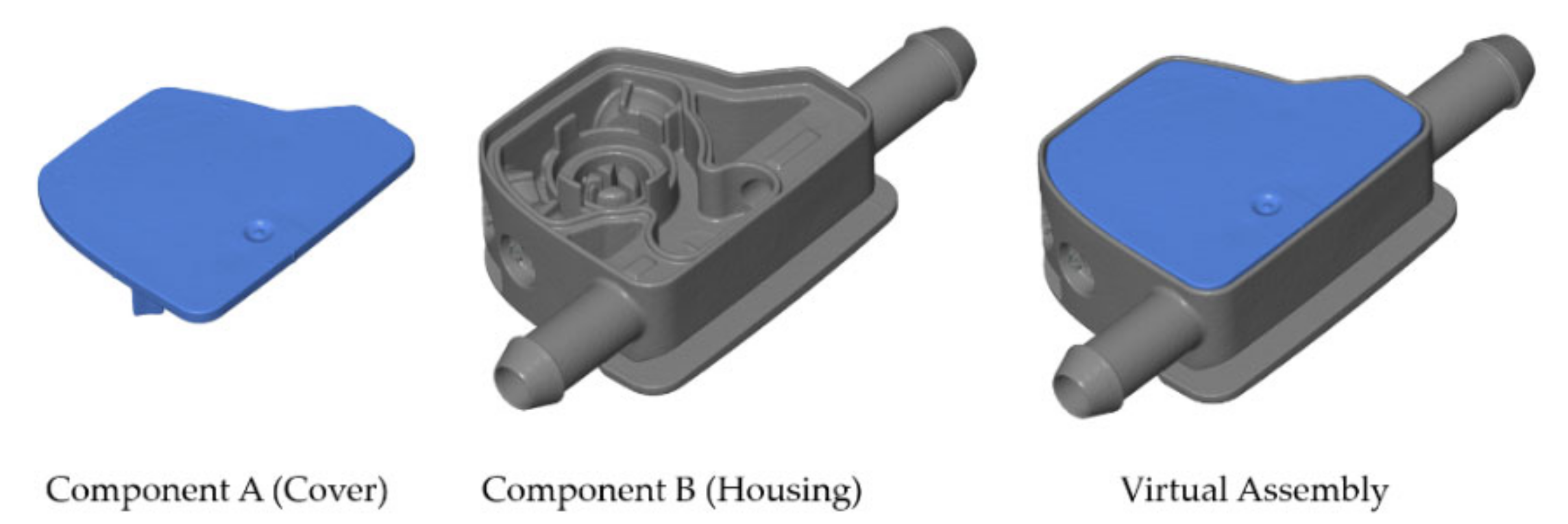
Unfortunately, the standardized approach lacks the consideration of form deviations. Thus, first approaches for virtual assembly (VA) were developed, where local form deviations are considered. An exemplary VA is shown in Figure 1. In Section 2, the VA approaches are described in detail. These concepts are based on skin model shapes (SMS) that describe a discrete, holistic representation of a measured part considering all relevant deviation types. The SMS concept is standardized in ISO 17450-1 [32]. SMS can either originate from generic data predicted from assumed deviations or expert knowledge about the manufacturing process (Prediction Stage), or from measurement data of particular parts (Observation Stage) as in this work [33].
Although by using SMS all relevant geometrical modalities (dimensional, position and form deviations) of the parts are considered in VA, the deficit of prior work is the negligence of influences from the joining process on the geometry of the simulated assembly. In various works, the significance of regarding the joining process for VA is emphasized. The work of Wärmefjord et al. [34] gives a comprehensive overview of factors affecting the geometrical quality of an assembly and outlines the need of considering these factors for VA.
1.3. Scope and Aims
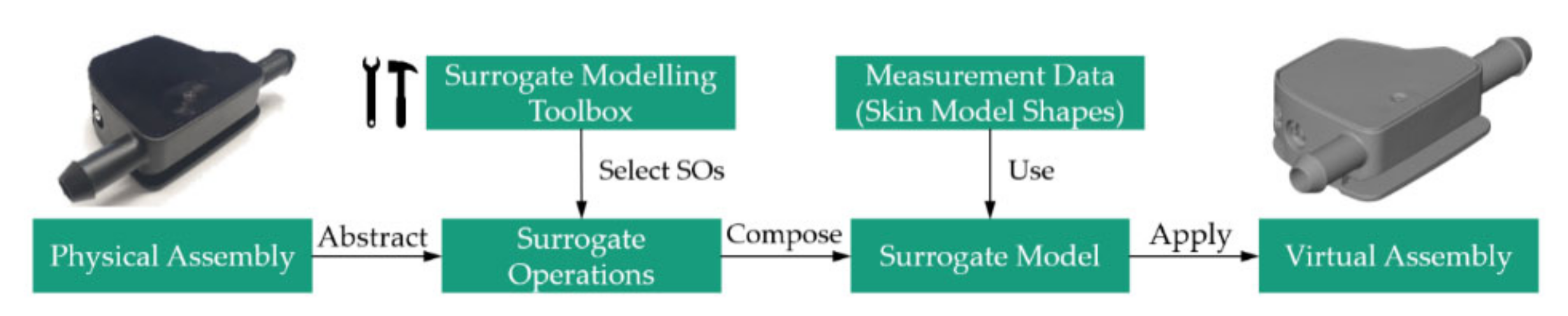
Joining processes are manifold and thus cannot be represented by a single generic algorithm for VA. For example in the application described in Section 4, a virtual intersection of the laser-welded assembly is allowed, which represents the welding bead. For a sheet metal assembly instead, elastic and plastic deformation should be considered that arises due to assembly forces, and virtual intersection is forbidden. The scope of this work is to develop a Surrogate Modelling Toolbox (SMT) that consists of Surrogate Operations (SOs) being composed to Surrogate Models (SMs). By selecting sufficient SOs that represent the influence on the assembly geometry due to the joining process at its best, an SM is composed that can be applied to the measured SMS representing particular parts. By doing so, a simulation of the assembly in the form of a virtual assembly can be performed. The outlined concept is shown in Figure 2. Here, the registration process is declared as “Virtual Assembly” and the registration result is denoted as “virtual assembly”.
The SMT concept aims at concatenating existing geometrical operations as SOs. The 3D Point Cloud Registration Toolbox described by Garcia [35] serves as model for the SMT approach. Moreover, the objective of the SMT concept is to provide a simplified alternative to existing approaches. These approaches are often computationally expensive and lack practical usability. For example, a single crash simulation of a passenger car crash takes up to 160 h so that an optimization of certain design parameters may take up to several months. By the abstraction into SMs, such complex models can be replaced by a simpler and less time-consuming input-output relationship [36].
A major aim of our work is to derive SOs that represent the most basic operations applicable to geometrical measurement data in order to manipulate the geometry of the assembly. A method to create SMs for VA is introduced that allows composing SMs from sufficient SOs that are contained in the SMT. Furthermore, a validation method is incorporated that enables comparing the process variation of both virtual and physical assemblies. These methods are applied step-by-step for a particular use case shown in Section 4.
The working hypothesis is that the geometrical behavior of joining processes can be described by SMs with a sufficient accuracy. This hypothesis requires that the influences on the geometry of an assembly are known and can be described mathematically by SOs. Here, the term “sufficient” stands for an application-specific accuracy, where in the first place joining processes with lower tolerance requirements are focused.
The central research question is, how far existing high precision approaches such as finite elements calculations, can be abstracted to easier, low precision SOs.
2. State of the Art
The structure of the SMT is based on the 3D Point Cloud Registration Toolbox from Garcia [35]. In this work, a broad overview of state-of-the-art registration techniques is given. A common registration algorithm pipeline is developed based on the researched algorithms. VA algorithms can be described by this pipeline as well. VA comprises registration algorithms, where measurement point sets are aligned by minimizing a specific objective function in order to find an optimal position and orientation of the point set to register to a reference point set. The pipeline developed in [35] consists of the four steps
- Detection (of key points in order to reduce the number of points to register),
- Description (of the shape by local shape descriptors),
- Searching (of corresponding points) and
- Refinement (in an iterative optimization).
For VA, the detection step is performed manually by defining the datum patches, which usually are defined in a technical drawing. The description step is neglected here. In a Best Fit registration, shape similarities are used to align the point sets. For VA instead, similarities determined during the detection step cannot be used, because the point sets to register do not necessarily have similar geometries. For both the searching and refinement steps, the review article of Liying et al. [37] gives a good overview, where the accuracy of registration strategies (pair-wise, multi-view), of search strategies (kd-tree, grid-closest-point), and of distance metrics (point to point, point to surface) is evaluated.
In the following Section 2.1, implementations for VA registration algorithms in the state of the art are described, where mainly the different realizations for the searching and refinement strategies are outlined. In Section 2.2, a general description of the terms Model and Surrogate Model as well as applications of SMs are provided.
2.1. Methods for Relative Positioning
In contrast to data fusion registrations such as the commonly known Best Fit registration, by VA not similarity in point sets, but corresponding contact faces are searched. This makes it necessary to implement constraints to the registration algorithm that represent physical effects of the corresponding real-world assembly. The underlying basic optimization problem stated in Equation (1) is a minimization problem of the sum of squared signed distances according to:
with as the three translational and rotational optimization parameters of the affine transformation, respectively. As a convention, negative signed distances denote a virtual intersection of the point sets. The sign is determined from the normal vectors of the measured surfaces, where the normal by convention points away from the surface’s material side. The most relevant constraint is the avoidance of intersection of point sets, which comprises the impossibility of parts to intersect. Commonly, the non-intersection is formulated as hard constraint allowing only signed distances between the point set to register and the rigid point set [30,38,39]. Pierce linearizes this constraint in order to simplify the underlying optimization problem [40]. By formulation as a soft constraint, a certain intersection of parts can be tolerated, e.g., to simulate the flattening of surfaces [41]. Using the Lagrange multiplier method, for the Lagrangian function as per:
the optimality condition is found by setting the partial derivatives equal zero according to:
In Equation (2), is the Lagrange multiplier and is the cardinality of a set of negative signed distances. The work of Shakarji and Srinivasan at the National Institute of Standards and Technology (NIST) includes such constraint registration methods for datum definitions considering L1 norm (Manhattan) [42] and L2 norm (Gaussian) distance metrics [29] and can be considered as preparatory research for future ISO and ASME standards as indicated e.g., in draft ISO/DIS 5459.2:2017 [43]. The basic optimization problem in our approach is extended by pre-alignment SOs and optimization constraints (during optimization) to consider the influence of the joining process on the geometrical quality of the assembly.
Another approach for relative positioning is the difference surface approach from Samper et al. [44]. The difference surface equals to the differences of corresponding form deviations of both contact faces. Form deviations are separated by modal decomposition as described in [45]. The contact points of both faces are computed by the intersection of the difference surface with a contact triangle that achieves a maximal surface area. As a constraint, the assembly force vector must intersect the contact triangle [44,46]. A further approach stated by Samper is the minimization of the convex hull of the difference volume (gap volume) between the contact faces.
2.2. Prior Work for Surrogate Modelling for Joining Processes
According to Stachowiak [47] a model is defined by the criteria mapping, reduction and pragmatism. Models represent a real-world system in a simplified mathematical description and are used in order to predict a system output for a known system input. The connection between inputs and outputs is mapped by a simplified black-box, grey-box or white-box model. Mapping means the representation of a real system by an artificial input-output connection that is reduced to the aspects that are relevant for the scope of the researched application (reduction). A model replaces the real system only for a particular application and is valid only under certain temporal and causal restrictions as well as for certain subjects (pragmatism). Validity is a fourth criterion introduced by Kastens [48], which states that a model should represent the real system with a certain quality.
The distinction between model and SM however is vague. In common practice, an SM means a simplified model for which no connection between inputs and outputs is known a-priori. Thus, the two main problems model construction (finding a sufficient SM) and model appraisal (assessing the model error) have to be dealt with [49]. By surrogate modelling, it is aimed to decrease the complexity for model formation and computation while maintaining a sufficient prediction quality [36]. Since SMs are less accurate due to simplification, they are mainly efficient for real-world problems that admit less detailed considerations.
In the scope of this work, SMs for joining processes are researched. The generic joining process according to Dahlström et al. [50] consists of the four steps Locating and Placement of parts in a fixture, Clamping of the parts, Joining and Releasing from the fixture [27], as shown in Figure 3.
SMs for geometrical properties map physical effects of the real-world assembly to geometrical deviations of the assembly. Influences on the geometry of the assembly from all four mentioned steps of the joining process need to be considered in the SM.
A systematic overview of factors effecting the geometrical quality is given by Wärmefjord et al. in [34]. Here, the authors mention influences from material properties, part variation, part collision, gravitational forces, the fixture and the joining process. A detailed discussion on influence factors is given in Section 3.
Prior work on surrogate modelling comprises the research of Grandjean et al., where the plastic deformations in the contact zone for a hip prosthesis assembly is considered [51,52]. The effective contact surface is computed by erosion of the surface morphology up to a state, where assembly and contact forces are in equilibrium. The approaches of Corrado and Polini [53,54] as well as Falgarone et al. [55] regard elastic deformation by implementing Finite Elements calculations in the contact simulation, implemented in the Cassino Unified Tolerance Analysis, and ANATOLEFLEX software, respectively. Liu and Hu introduced the Method of Influence Coefficients, where the connection between initial part deviations, assembly forces and resulting assembly deviations is linearized by means of a sensitivity matrix [56,57]. Andolfatto et al. explore the use of neural networks for the geometrical variation propagation in assemblies concerning geometrical features from GD&T tolerances such as tolerance of size, location and form [58]. The mentioned concepts are either complex to apply or application-specific and thus indicate the need for a simplified, generic approach.
Non-geometrical SMs, where a certain geometrical propagation method is already presumed, include tolerance-cost relationships in assemblies [59], optimizations of joining processes such as optimized spot welding sequences [60] and functional relationships such as the use of neural networks for the prediction of tooth root stress of not form-ideal gear wheel assemblies [61].
3. Development of a Surrogate Modelling Toolbox
Influence quantities on the geometrical quality of an assembly are shown in Figure 4, based on the work of Wärmefjord et al. [34]. The listing is in progress and may be further extended by additional influence factors that arise from further studied joining processes.
We consider in this work joining processes classified according to norm DIN 8593-0 [62]. The joining methods Composing (e.g., Snap Fit) and Pressing (e.g., Press fit) mainly effect the assembly geometry due to elastic and plastic deformations caused by joining forces as stated in [63]. The joining methods Primary Forming (e.g., overmoulding, factors on geometrical quality are researched in [64]), Recasting (e.g., riveting [65]), Welding (e.g., laser welding [66]), Soldering and Bonding mainly effect the geometry due to warpage and shrinkage caused by thermal stress [62,67].
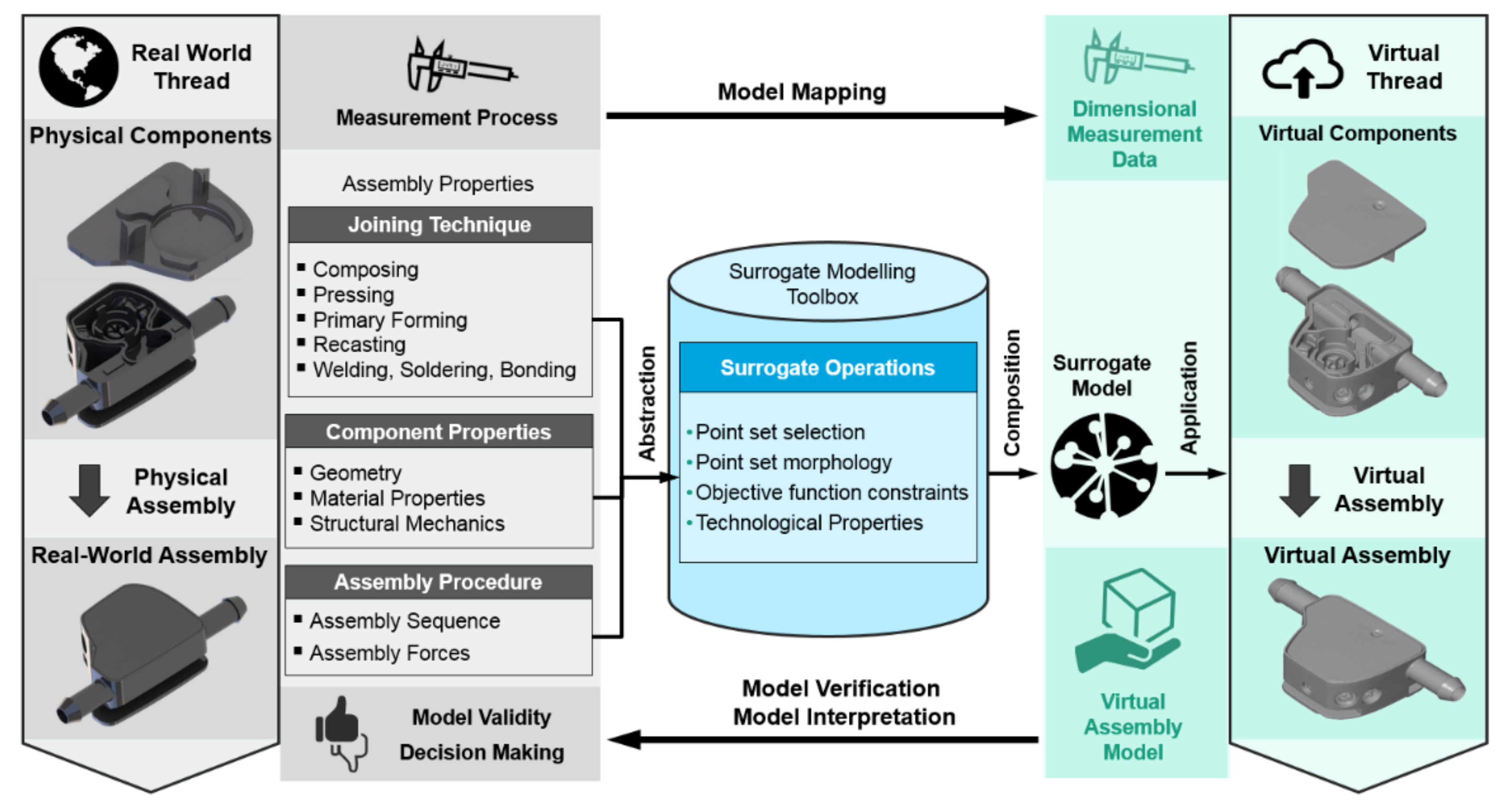
Figure 5 depicts the Surrogate Modelling process, where the real world process is linked to the virtual process domain by Model Mapping (physical to virtual thread) as well as Model Verification and Model Interpretation (virtual to physical thread). Suitable SOs are abstracted from assembly properties such as the Joining Technique, Component Properties and the Assembly Procedure. By the composition of an SM, which is deployed to the measured SMS of the parts, a virtual assembly is simulated regarding the influences of the physical assembly on the assembly’s geometrical quality. SOs determined for this work are arranged in Table A1 (cf. Appendix A), which are separated into
- Operations for detecting relevant subsets of points (Point set selection),
- Operations for describing and manipulating the surface morphology (Point set morphology),
- Operations concerning point correspondence search and assembly position determination (Objective function constraints) and
- Technological properties such as point set refinement or simplification operations, which are not further discussed in this work.
SOs either can be implemented as the aforementioned optimization constraints during the refinement step [35] or are applied to the measurement data before the registration process (pre-alignment SOs). In Table A1, a listing of SOs for both domains is given, which can be extended with further operations in the future.
Both the identification of relevant SOs and the composition of an SM are relevant steps that influence the outcome of the VA algorithm. In order to verify the developed SM, a validation method is proposed in Section 4.2. By means of this method the outcome of the SM is compared to the physical assembly (PA). Therefore, process statistics from multiple virtual and physical assemblies are evaluated. By assessing the process variation, the impact of part-individual deviations is evaded.
4. Use Case Study for a Laser Welding Assembly
As use case a two-component assembly of a housing and a cover made from a thermoplastic polymer is studied since an assembly of two components represents the basic assembly sequence that can be further enlarged to elaborate multi-component assemblies. Here, industrial computed tomography (CT) is used for capturing the geometrical measurement data.
The CT scans were performed at an acceleration voltage of 180 kV, a tube current of 300 µA, an integration time of 334 ms, 1000 projection images per scan, a voxel size of 0.1006 mm and without physical pre-filtering. The used CT system is a TomoScope HV 500 (Werth, Gießen, Germany).
Both components are joined by means of laser transmission welding. Thereby, the component facing towards the laser source is optically transparent to the used laser wavelength and the component facing away is locally melted due to absorbing laser energy. For the presented assembly, a laser welding system of bielomatik GmbH incorporating a quasi-simultaneous welding process is used. This process allows equally melting the complete welding bead by quickly moving the laser beam along the bead contour. The mentioned welding bead that characterizes the weld and which is considered for a further quality analysis is shown in Figure 6. The welding bead is marked in green and shows virtual intersection. This overlap is dedicated as material reservoir for the welding process and thus correlates strongly with the assembly quality. Subjecting welded assemblies to several temperature variations can provoke assembly failures that are correlated with the welding bead geometry. Hence, this particular use case was chosen as a representative application with known optimization potential worth investigating.
4.1. Surrogate Model Composition
The SM for the outlined example, as shown in Figure 7, is composed of the following SOs:
- Coarse Pre-Alignment according to the CAD assembly,
- Patch Selection of primary datum A (guiding pegs A1 and A2 at the cover and corresponding holes in the housing, see technical drawing in Figure 7) and secondary datum B (alignment of cover face in flush with the housing), and
- Virtual Intersection of the parts by using a penalty-based optimization approach as in [68].
The Coarse Alignment is used in order to reduce the search distance for the point correspondence search to a feasible magnitude. By Patch Selection, the assembly sequence is considered since both parts are joined along the datums A and B. By Virtual Intersection, the joining process is simulated, where the material reservoir in the welding bead is melted during the laser welding process. These particular SMs were selected with regard to technical specifications and the assembly procedure.
4.2. Validation against the Physical Assembly
To validate the described SM, both virtual and physical assemblies are compared, according to their variation distributions in Section 4.2.1, and spatially resolved in single points in Section 4.2.2. As distributions provide an overview of the extent of variation, the single point consideration allows capturing the variation related to a particular location. The point sets are aligned over the housing geometry with an unconstrained Best Fit registration. All evaluations are performed for the top face of the cover, since the cover is virtually assembled to the geometrically fixed housing.
4.2.1. Comparison of Variation Distributions
In order to quantify the variation, the mean variation is introduced, which is defined as the arithmetic mean:
To assess the mean variation of the virtual assemblies and the physical assemblies, and respectively, are considered in the following. In Equation (4), is the Euclidean distance between point and average point from W repetitions. In our work, 24 repeated virtual assemblies and three physical assemblies are studied. is determined as the mean coordinate from the repeated scans, where points are associated by means of a k-nearest-neighbor search. The quantities and P are computed for all N point associations , where is the point index variable.
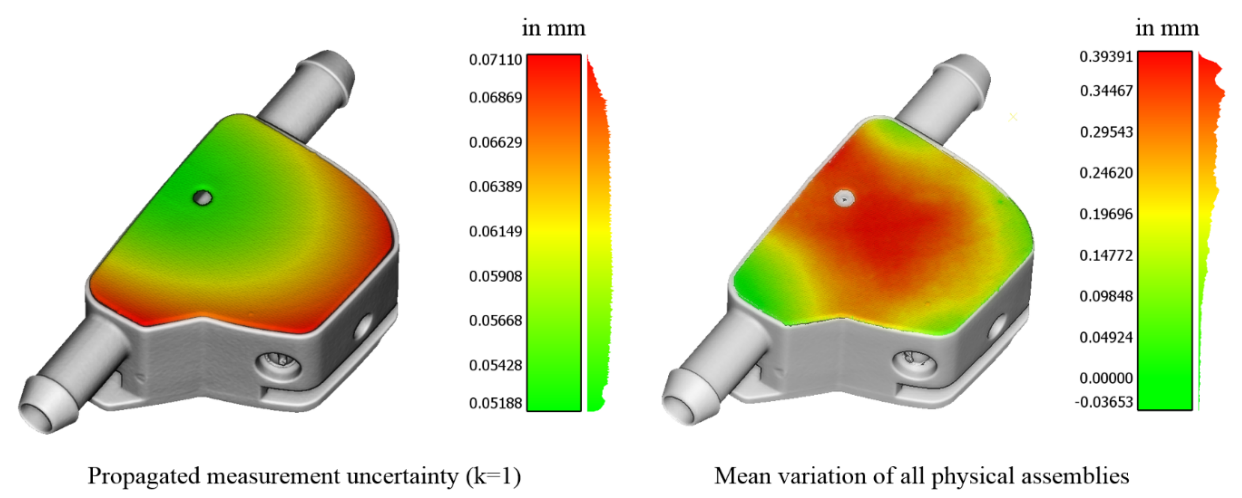
The average manufacturing deviations and of the covers and housings, respectively, are determined analogously to Equation (4) as mean deviations from the respective mean value for all 24 covers and housings. They are normally distributed (their mean values are equal to approx. 0.03 mm) and are about ten times smaller than the mean variation of all physical assemblies (up to max. 0.4 mm). Values for are shown in Figure 8 (right). Thus in a first approximation, the influence of the manufacturing deviations on assembly variations is neglected, because they contribute to less than 10% of the extent of the variation of all physical assemblies .
The propagated uncertainty of the virtual assembly comprises the uncertainty of measurement points that arises from 20 CT scan repetitions. The uncertainty is further increased by the transformation uncertainty emerging at VA, which causes a slight variation of the determined assembly position and orientation of the point set to register for repeated registrations. The subscript “P” denotes the transformed state that is gathered by using a linear uncertainty propagation method. Here, an uncertainty coverage factor of as defined in ISO/IEC 98-3 [69] is applied. The uncertainty is shown in Figure 8 (left) and is in range of up to ca. 0.07 mm. For the transformed point set, equals to the standard deviation of the VA variation .
Figure 9 shows the mentioned distributions of assembly and manufacturing deviations. The bias represents the mean systematic offset between VA and PA distributions, which is about 0.16 mm.
The variation interval for VA lays inside the PA interval. Since the real process variates more than its simulation, an averaging or smoothing effect due to CT measurement and VA algorithm is assumed. As the variation of the PA complies with the process requirements, the VA variation complies as well. In this comparison of distributions only probabilistic statements can be given. Thus, in a spatially resolved comparison, the compliance for each single measurement point is evaluated.
4.2.2. Comparison of Single Point Deviations
In order to compare single measurement points, the exploitation ratio R is introduced. Therefore, the VA variation is analyzed in relation to the PA variation . The ratio R is defined as:
If the R-value equals 100%, the VA variation equals the PA variation. For an R-value smaller than 100%, the variation determined by VA is smaller than the variation of the real joining process. In this case, the SM applied for VA is considered as sufficiently precise. We assume points with as good predictions.
As shown in the color-coded 3D visualization of the R-values in Figure 10, this applies to most regions of the cover, which are colored in blue to green. However, yellow and red colors denote regions where the VA variation exceeds the PA variation. The histogram in Figure 10 denotes the distribution of R-values. About 77.3% of all points are smaller than an R-value of 100%. Thus, the chosen SM is assumed as a sufficient assembly prediction for the majority of points. However, the regions in the edges of the cover marked in red indicate, that further geometrical factors need to be incorporated, which are not considered in the chosen SM.
5. Conclusions
The regions for represent the edges of the cover. A large R-value in these regions is either due to an increased variation of the VA or due to a decreased variation of the PA. Here, both explanations apply, since the variation of the VA is increased due to a larger propagated uncertainty in these regions, and due to a decreased variation of the PA. Both effects are visualized in Figure 8.
In order to improve the VA prediction accuracy, the SM can be further detailed by considering geometrical factors influencing the edges of the joined part. For this assembly, the clamping of the cover is likely to influence these regions, which might be included as an additional SO. Therefore, the SOs depicted in Table A1 (cf. Appendix A) can be studied.
Altogether, the developed SMT and the validation by the R-value constitute sufficient methods in order to identify SMs for the prediction of an assembly’s geometrical quality. The assembly’s geometrical quality comprises all quality features that directly or indirectly depend on the geometry of the assembly. This might include perceived quality such as the body-in-white clearance gap width [70] or to predict functional requirements such as a tight fit of a sealing. Assembly quality prediction (or geometrical propagation) is a crucial step for tolerance management. Consequently, the performed work constitutes a relevant contribution to the assembly geometry prediction needed for a precise tolerance management.
6. Outlook
In future work, the presented use case can be further investigated by a detailed evaluation of the effects arising at the edges of the assembly. Therefore, potential physical causes can be studied, which can be abstracted into SOs and a more sophisticated SM.
In order to state further results more precisely, a larger batch of physical assemblies can be considered. Presumably, the PA variation in a larger batch will be also larger, whereby the R-values will become smaller and thus the SM becomes more feasible. Moreover, further use cases can be studied in order to assess the transferability of the determined SMT to other applications. Therefore, other joining methods than laser welding can be regarded.
The welding seam surface of the PA cannot be reconstructed by means of CT, because the cover and housing cannot be separated. As a consequence, no comparison of the R-value in the welding seam can be performed. Thus, the top face of the cover is considered for the verification. As manufacturing deviations can be neglected, the top face sufficiently represents the welding seam geometry. For further research however, it might be promising to directly evaluate the R-value at the datum features.
Author Contributions
Conceptualization, M.K.; methodology, M.K.; software, M.K.; validation, M.K., I.E. and M.F.H.; formal analysis, I.E. and M.F.H.; investigation, M.K.; resources, I.E., M.F.H.; data curation, M.K.; writing—original draft preparation, M.K.; writing—review and editing, M.F.H. and I.E.; visualization, M.K.; supervision, M.F.H.; project administration, I.E.; funding acquisition, M.F.H., I.E. All authors have read and agreed to the published version of the manuscript.
Funding
This research was funded by Ministerium für Wirtschaft, Arbeit und Wohnungsbau Baden-Württemberg within the center for cyber cognitive intelligence (CCI), grant number 017-192996. The APC was funded by the Fraunhofer Publication Fund.
Institutional Review Board Statement
Not applicable.
Informed Consent Statement
Not applicable.
Data Availability Statement
The data presented in this study are available on request from the corresponding author. The data are not publicly available due to privacy issues.
Acknowledgments
Special thanks to Beiß from bielomatik GmbH for supplying the use case material. The authors are grateful for the assistance of the anonymous reviewers helping to improve this paper.
Conflicts of Interest
The authors declare no conflict of interest. The funders had no role in the design of the study; in the collection, analyses, or interpretation of data; in the writing of the manuscript, or in the decision to publish the results.
Nomenclature
| CPS | Cyber-Physical Systems |
| CT | Computed Tomography |
| GD&T | Geometrical Dimensioning and Tolerancing |
| ICT | Information and Communication Technology |
| PA | Physical Assembly |
| SMS | Skin Model Shape |
| SMT | Surrogate Modelling Toolbox |
| SO | Surrogate Operation |
| VA | Virtual Assembly |
Appendix A

Table A1.
Overview of considered Surrogate Operations (Pre-alignment SOs are denoted by superscript A, optimization constraints are denoted by superscript B). By the statement of the level of detail, the SOs are classified concerning their level of abstraction.
Table A1.
Overview of considered Surrogate Operations (Pre-alignment SOs are denoted by superscript A, optimization constraints are denoted by superscript B). By the statement of the level of detail, the SOs are classified concerning their level of abstraction.
| Surrogate Operation | Description | Reference | Level of Detail |
|---|---|---|---|
| Point set selection | Detection of relevant subsets of points | ||
| Coarse Matching | Determine initial position before assembly closely to the final position [35] | ||
| Unconstrained Best Fit A | Alignment as provided by Iterative Closest Point-Algorithm (ICP) | [71] |  |
| Constrained Regular Geometries A | Alignment as provided by the ISO System for Geometrical Product Specification (GPS) datum definition in ISO 5459 [28] | [28] |  |
| Segmentation of contact faces A | Determination of subsets and that are by mechanical design provided as contact faces | ||
| Local shape descriptors A | Determination of hypothetically corresponding, salient key features in and , such as Principal Curvature or Harris Algorithm [72] | [35,72] | |
| Semantic segmentation A | Determination of subsets corresponding to geometrical primitives | [73] | |
| Patch Selection (CAD based) A | Determination of subsets corresponding to a maximal distance to a nominal geometry such as a CAD file | [74] |  |
| Point set morphology | Description and manipulation of the surface morphology | ||
| Definition of Offset and Intersection A | Definition of a certain offset between faces (e.g., to simulate adhesive gap) or of an intersection (virtual penetration) to simulate surface flattening or material loss (e.g., due to melting welding bead) | [41] | |
| Morphological Filtering A | Manipulate surfaces locally to simulate surface flattening due to mechanical load | [51,52] | |
| Hertzian Contact Formulation A | [41] | | |
| Method of Influence Coefficients (MIC) A | Linearized computation of elastic deformation due to mechanical load | [50,57] | |
| Linear Finite Element Analysis (FEA) A | Computation of elastic deformation due to mechanical load | [75,76] | |
| Nonlinear FEA A | Computation of elastic and plastic deformation due to mechanical load | [65,66] | |
| Objective Function | Searching of correspondences and the assembly position | ||
| Modalities for Distance Computation | Approaches to compute distances between and | ||
| Point to Point B | Distance computation discretized on single points | [71] | |
| Point to Plane or Triangle B | Triangle-based algorithms for distance calculation that more precisely represent the physical distance | [77] | |
| Point correspondence metric | Metric considered to determine corresponding points recreating the physical contact scenario [38] | ||
| Euclidean distance B | Only sufficient, when point clouds are relatively dense | [38] | |
| Ray Casting in Normal Direction B | Improved correspondence for surfaces that are sufficiently coarse aligned | [38] | |
| Ray Casting in Assembly Direction B | Most accurate representation of the physical assembly contact correspondence | [38] | |
| Distance Metric | Metric considered to determine the discrepancy between and | ||
| Convex Hull of Gap Volume B | Minimization of the convex hull of the gap volume between and | [38] | |
| Euclidean distance B | Minimization of local distances in corresponding points | [38] | |
| Collision behavior | Collision behaviour stating an elastic or stiff contact | ||
| Penalize Intersection B | Allows a certain virtual intersection | [41] | n/a |
| Hard-Constrained Intersection B | Strict compliance to non-intersection | [41] | n/a |
| Collision detection | Determination and quantification of a collision between and | ||
| Sign of signed distances B | Negative signed distances represent a local intersection | [38] | |
| Simplex-based B | Fast, approximative collision detection, only applicable for convex geometries, e.g., the GJK algorithm [78] | [78,79] | |
| Bounding Volume Hierarchy B | More precise method applicable for closely positioned objects and initial collision | [79] | |
| Datum Hierarchy | Representation of primary, secondary, tertiary datum hierarchy as per [28] | ||
| Datum Weighting B | Weighting factors applied to the objective values derived from primary, secondary and tertiary patches | [38] | |
| Contact and Force Equilibrium B | Allow contact configurations only, where the contact triangle of the primary datum is maximized and intersected by the assembly force vector. The secondary datum constitutes a line contact and the tertiary datum a point contact. | [51] | |
References
- International Standardization Organization. Quality Management Systems. Fundamentals and Vocabulary; Beuth Verlag GmbH: Berlin, Germany, 2015. [Google Scholar]
- Kayasa, M.J.; Herrmann, C. A Simulation-based evaluation of selective and adaptive production systems (SAPS) supported by quality strategy in production. Procedia CIRP 2012, 3, 14–19. [Google Scholar] [CrossRef] [Green Version]
- Kang, H.; Li, Z.-M. Assembly research of aero-engine casing involving bolted connection based on rigid-compliant coupling assembly deviation modeling. Proc. Inst. Mech. Eng. Part C J. Mech. Eng. Sci. 2020, 234, 2803–2820. [Google Scholar] [CrossRef]
- Zmarzły, P. Technological Heredity of the Turning Process. Teh. Vjesn. Tech. Gaz. 2020, 27, 1194–1203. [Google Scholar] [CrossRef]
- Schleich, B.; Wärmefjord, K.; Söderberg, R.; Wartzack, S. Geometrical Variations management 4.0: Towards next Generation geometry assurance. Procedia CIRP 2018, 75, 3–10. [Google Scholar] [CrossRef]
- Söderberg, R.; Lindkvist, L.; Wärmefjord, K.; Carlson, J.S. Virtual geometry assurance process and toolbox. Procedia CIRP 2016, 43, 3–12. [Google Scholar] [CrossRef]
- Maropoulos, P.G.; Ceglarek, D. Design verification and validation in product lifecycle. CIRP Ann. 2010, 59, 740–759. [Google Scholar] [CrossRef]
- Kagermann, H.; Wahlster, W.; Helbig, J. Securing the Future of German Manufacturing Industry: Recommendations for Implementing the Strategic Initiative Industrie; National Academy of Science and Engineering: München, Germany, 2013. [Google Scholar]
- Hermann, M.; Pentek, T.; Otto, B. Design principles for industrie 4.0 scenarios. In Proceedings of the 2016 IEEE 49th Hawaii International Conference on System Sciences (HICSS), Koloa, HI, USA, 5–8 January 2016; pp. 3928–3937. [Google Scholar]
- Monostori, L.; Kádár, B.; Bauernhansl, T.; Kondoh, S.; Kumara, S.R.; Reinhart, G.; Sauer, O.; Schuh, G.; Sihn, W.; Ueda, K. Cyber-physical systems in manufacturing. CIRP Ann. 2016, 65, 621–641. [Google Scholar] [CrossRef]
- Dalenogare, L.S.; Benitez, G.B.; Ayala, N.F.; Frank, A.G. The expected contribution of industry 4.0 technologies for industrial performance. Int. J. Prod. Econ. 2018, 204, 383–394. [Google Scholar] [CrossRef]
- Bauernhansl, T.; Ten Hompel, M.; Vogel-Heuser, B. Industrie 4.0 in Produktion, Automatisierung und Logistik; Springer Fachmedien Wiesbaden: Wiesbaden, Germany, 2014; ISBN 978-3-658-04681-1. (In German) [Google Scholar]
- Bauer, W.; Schlund, S.; Marrenbach, D.H.; Ganschar, O. Industrie 4.0—Volkswirtschaftliches Potential für Deutschland.; Bitkom: Berlin, Germany, 2014; Available online: https://www.bitkom.org/Bitkom/Publikationen/Industrie-40-Volkswirtschaftliches-Potenzial-fuer-Deutschland.html (accessed on 14 January 2021). (In German)
- Li, D.; Fast-Berglund, Å.; Paulin, D. Current and future industry 4.0 capabilities for information and knowledge sharing. Int. J. Adv. Manuf. Technol. 2019, 105, 3951–3963. [Google Scholar] [CrossRef] [Green Version]
- Rüßmann, M.; Lorenz, M.; Gerbert, P.; Waldner, M.; Justus, J.; Engel, P.; Harnisch, M. Industry 4.0: The Future of Productivity and Growth in Manufacturing; Boston Consulting Group: Boston, MA, USA, 2015. [Google Scholar]
- Bauernhansl, T.; Hartleif, S.; Felix, T. The Digital Shadow of production—A concept for the effective and efficient information supply in dynamic industrial environments. Procedia CIRP 2018, 72, 69–74. [Google Scholar] [CrossRef]
- Rosen, R.; Von Wichert, G.; Lo, G.; Bettenhausen, K.D. About the importance of autonomy and digital twins for the future of manufacturing. IFAC-Papersonline 2015, 48, 567–572. [Google Scholar] [CrossRef]
- Glaessgen, E.; Stargel, D. The digital twin paradigm for future NASA and U.S. air force vehicles. In Proceedings of the 53rd AIAA/ASME/ASCE/AHS/ASC Structures, Structural Dynamics and Materials Conference, Honolulu, HI, USA, 23–26 April 2012; American Institute of Aeronautics and Astronautics, Ed.; American Institute of Aeronautics and Astronautics: Reston, VA, USA, 2012; p. 1818. [Google Scholar]
- Schleich, B.; Anwer, N.; Mathieu, L.; Wartzack, S. Shaping the digital twin for design and production engineering. CIRP Ann. 2017, 66, 141–144. [Google Scholar] [CrossRef] [Green Version]
- Dobrzański, L.A. Role of materials design in maintenance engineering in the context of industry 4.0 idea. J. Achiev. Mater. Manuf. Eng. 2019, 1, 12–49. [Google Scholar] [CrossRef]
- Dobrzański, L.A.; Dobrzański, L.B. Dentistry 4.0 concept in the design and manufacturing of prosthetic dental restorations. Process. 2020, 8, 525. [Google Scholar] [CrossRef]
- Dobrzański, L.A.; Dobrzański, L.B. Approach to the design and manufacturing of prosthetic dental restorations according to the rules of industry 4.0. Mater. Perform. Charact. 2020, 9, 394–476. [Google Scholar] [CrossRef]
- Wärmefjord, K.; Söderberg, R.; Lindkvist, L.; Lindau, B.; Carlson, J.S. Inspection data to support a digital twin for geometry assurance. In Advanced Manufacturing; Gupta, K., Ed.; ASME International: Tampla, FL, USA, 2017. [Google Scholar]
- Lanza, G.; Haefner, B.; Kraemer, A. Optimization of selective assembly and adaptive manufacturing by means of cyber-physical system based matching. CIRP Ann. 2015, 64, 399–402. [Google Scholar] [CrossRef] [Green Version]
- Nielsen, H.S. New concepts in specifications, operators and uncertainties. In Proceedings of the 8th CIRP International Seminar on Computer Aided Tolerancing—Managing Geometric Uncertainty in the Product Lifecycle, Charlotte, NC, USA, 28–29 April 2003; Wilhelm, R.G., Ed.; The University of North Carolina at Charlotte, The Center for Precision Metrology: Charlotte, NC, USA, 2003; pp. 1–6. [Google Scholar]
- Gröger, S. Qualifizierung der 3D-Koordinatenmesstechnik zur standardisierten Bildung von Bezügen und Bezugssystemen (3D-BBS); Technische Universität Chemnitz: Chemnitz, Germany, 2015. (In German) [Google Scholar]
- Li, Y.; Zhao, Y.; Yu, H.; Lai, X. Compliant assembly variation analysis of sheet metal with shape errors based on primitive deformation patterns. Proc. Inst. Mech. Eng. Part C J. Mech. Eng. Sci. 2018, 232, 2334–2351. [Google Scholar] [CrossRef]
- Deutsches Institut für Normung, E.V. Geometrische Produktspezifikation (GPS)—Geometrische Tolerierung. Bezüge und Bezugssysteme; Deutsche Fassung: Berlin, Germany, 2011. (In German) [Google Scholar]
- Shakarji, C.M.; Srinivasan, V. Toward a new mathematical definition of datums in standards to support advanced manufacturing. In Proceedings of the ASME 13th International Manufacturing Science and Engineering Conference—2018, College Station, TX, USA, 18–22 June 2018; ASME: New York, NY, USA, 2018. ISBN 978-0-7918-5137-1. [Google Scholar]
- Weißgerber, M.; Keller, F. Datum systems in coordinate measuring technique. In Proceedings of the XIth International Science Conference Coordinate Measuring Technique, Bielsko-Biala, Poland, 2–4 April 2014; Sładek, J., Jakubiec, W., Eds.; University of Bielsko-Biala, Laboratory of Metrology: Bielsko-Biała, Poland, 2015; pp. 77–81, ISBN 9788363713881. [Google Scholar]
- Weißgerber, M.; Ebermann, M.; Gröger, S.; Leidich, E. Requirements for datum systems in computer aided tolerancing and the verification process. Procedia CIRP 2016, 43, 238–243. [Google Scholar] [CrossRef] [Green Version]
- Deutsches Institut für Normung, E.V. Geometrische Produktspezifikation (GPS)—Grundlagen—Teil 1: Modell für die Geometrische Spezifikation und Prüfung; Beuth: Berlin, Germany, 2012. (In German) [Google Scholar]
- Schleich, B.; Anwer, N.; Mathieu, L.; Wartzack, S. Skin model shapes: A new paradigm shift for geometric variations modelling in mechanical engineering. Comput. Des. 2014, 50, 1–15. [Google Scholar] [CrossRef]
- Wärmefjord, K.; Söderberg, R.; Lindau, B.; Lindkvist, L.; Lorin, S. Joining in nonrigid variation simulation. In Computer-Aided Technologies—Applications in Engineering and Medicine; Udroiu, R., Ed.; IntechOpen: Rijeka, Croatia, 2016; p. 42. [Google Scholar]
- Garcia, F.R. Tools for 3D Point Cloud Registration. Master’s Thesis, University of Girona, Girona, Spain, 2017. [Google Scholar]
- Jiang, P.; Zhou, Q.; Shao, X. Surrogate Model-Based Engineering Design and Optimization; Springer Nature: Singapore, 2020. [Google Scholar]
- Liying, W.; Weidong, S. A review of range image registration methods with accuracy evaluation. In Proceedings of the 2009 Joint Urban Remote Sensing Event, Shanghai, China, 20–22 May 2009. [Google Scholar]
- Schleich, B.; Wartzack, S. Approaches for the assembly simulation of skin model shapes. Comput. Aided Des. 2015, 65, 18–33. [Google Scholar] [CrossRef]
- Floery, S. Constrained Matching of Point Clouds and Surfaces. Master’s Thesis, Technische Universität Wien, Wien, Austria, 2010. [Google Scholar]
- Pierce, R.S.; Rosen, D. Simulation of mating between non-analytic surfaces using a mathematical programming formulation. In Proceedings of the International Design Engineering Technical Conferences and Computers and Information in Engineering Conference, Long Beach, CA, USA, 24–28 September 2005; ASME: New York, NY, USA, 2005; pp. 179–188. [Google Scholar]
- Banerjee, A.; Chanda, A.; Das, R. Historical origin and recent development on normal directional impact models for rigid body contact simulation: A critical review. Arch. Comput. Methods Eng. 2016, 24, 397–422. [Google Scholar] [CrossRef]
- Shakarji, C.M.; Srinivasan, V. Theory and Algorithms for L1 Fitting Used for Planar Datum Establishment in Support of Tolerancing Standards. In Proceedings of the 2012 ASME International Design Engineering Technical Conferences and Computers and Information in Engineering Conference, Portland, OR, USA, 4–7 September 2013; ASME: New York, NY, USA, 2013. [Google Scholar]
- Deutsches Institut für Normung, E.V. Geometrische Produktspezifikation (GPS)—Geometrische Tolerierung—Bezüge und Bezugssysteme; Beuth: Berlin, Germany, 2017. (In German) [Google Scholar]
- Samper, S.; Adragna, P.-A.; Favreliere, H.; Pillet, M. Modeling of 2D and 3D assemblies taking into account form errors of plane surfaces. J. Comput. Inf. Sci. Eng. 2009, 9, 041005. [Google Scholar] [CrossRef]
- Formosa, F.; Samper, S. Modal Expression of Form Defects. In Models for Computer Aided Tolerancing in Design and Manufacturing; Davidson Joseph, K., Ed.; Springer: Dordrecht, The Netherlands, 2007; pp. 13–22. [Google Scholar]
- Grandjean, J.; Ledoux, Y.; Samper, S. Influence of form errors in plane surface assemblies. In Proceedings of the MProVE 2011—International Conference on Innovative Methods in Product Design, Venice, Italy, 15–17 June 2011; pp. 516–520. [Google Scholar]
- Stachowiak, H. Allgemeine Modelltheorie; Springer: Berlin/Heidelberg, Germany, 1973. [Google Scholar]
- Kastens, U.; Kleine Büning, H. Modellierung. Grundlagen und formale Methoden, 4., erweiterte Auflage; Hanser: Munich, Germany, 2018; ISBN 9783446455399. [Google Scholar]
- Queipo, N.V.; Haftka, R.T.; Shyy, W.; Goel, T.; Vaidyanathan, R.; Tucker, P.K. Surrogate-based analysis and optimization. Prog. Aerosp. Sci. 2005, 41, 1–28. [Google Scholar] [CrossRef] [Green Version]
- Dahlström, S.; Lindkvist, L. variation simulation of sheet metal assemblies using the method of influence coefficients with contact modeling. J. Manuf. Sci. Eng. 2007, 129, 615–622. [Google Scholar] [CrossRef]
- Grandjean, J. Influence des Défauts de Forme sur les Performances D’assemblages: Application aux Prothèses Totales de Hanche. Master’s Thesis, Université de Grenoble, Grenoble, France, 2013. (In French). [Google Scholar]
- Grandjean, J.; LeDoux, Y.; Samper, S. On the role of form defects in assemblies subject to local deformations and mechanical loads. Int. J. Adv. Manuf. Technol. 2012, 65, 1769–1778. [Google Scholar] [CrossRef]
- Corrado, A.; Polini, W. FEA integration in the tolerance analysis using skin model shapes. Procedia CIRP 2018, 75, 285–290. [Google Scholar] [CrossRef]
- Polini, W.; Corrado, A. Digital twin of composite assembly manufacturing process. Int. J. Prod. Res. 2020, 58, 5238–5252. [Google Scholar] [CrossRef]
- Falgarone, H.; Thiébaut, F.; Coloos, J.; Mathieu, L. Variation simulation during assembly of non-rigid components. realistic assembly simulation with anatoleflex software. Procedia CIRP 2016, 43, 202–207. [Google Scholar] [CrossRef]
- Liu, S.C.; Hu, S.J. variation simulation for deformable sheet metal assemblies using finite element Methods. J. Manuf. Sci. Eng. 1997, 119, 368–374. [Google Scholar] [CrossRef]
- Polini, W.; Corrado, A. Methods of influence coefficients to evaluate stress and deviation distribution of flexible assemblies—A review. Int. J. Adv. Manuf. Technol. 2020, 107, 2901–2915. [Google Scholar] [CrossRef]
- Andolfatto, L.; Thiébaut, F.; Douilly, M.; Lartigue, C. On neural networks’ ability to approximate geometrical variation propagation in assembly. Procedia CIRP 2013, 10, 224–232. [Google Scholar] [CrossRef]
- Hallmann, M.; Schleich, B.; Wartzack, S. From tolerance allocation to tolerance-cost optimization: A comprehensive literature review. Int. J. Adv. Manuf. Technol. 2020, 107, 4859–4912. [Google Scholar] [CrossRef]
- Tabar, R.S.; Wärmefjord, K.; Söderberg, R. A new surrogate model–based method for individualized spot welding sequence optimization with respect to geometrical quality. Int. J. Adv. Manuf. Technol. 2019, 106, 2333–2346. [Google Scholar] [CrossRef] [Green Version]
- Haefner, B.; Biehler, M.; Wagner, R.; Lanza, G. Meta-Model based on artificial neural networks for tooth root stress analysis of micro-gears. Procedia CIRP 2018, 75, 155–160. [Google Scholar] [CrossRef]
- Deutsches Institut für Normung E.V. Fertigungsverfahren Fügen; Beuth Verlag GmbH: Berlin, Germany, 2003. [Google Scholar]
- Mori, K. Joining processes by plastic deformation. Adv. Mater. Res. 2014, 966, 29–47. [Google Scholar] [CrossRef]
- Bouwman, M.B.; Donderwinkel, T.; Krämer, E.; Wijskamp, S.; Costa, F. Overmolding—An integrated design approach for dimensional accuracy and strength of structural parts. In Proceedings of the 3rd Annual Composites and Advanced Materials Expo. CAMX 2016—Composites and Advanced Materials Expo, Anaheim, CA, USA, 26–29 August 2016. [Google Scholar]
- Neugebauer, R.; Rössinger, M.; Wahl, M.; Schulz, F.; Eckert, A.; Schützle, W. Predicting dimensional accuracy of mechanically joined car body assemblies. Key Eng. Mater. 2011, 473, 973–980. [Google Scholar] [CrossRef]
- Neugebauer, R.; Bernhardi, O.; Wahl, M.; Schulz, F.; Mauermann, R.; Schützle, W.; Werner, S. Predicting dimensional accuracy of laser welded aluminum add-on body parts. Key Eng. Mater. 2013, 549, 463–470. [Google Scholar] [CrossRef]
- Spur, G. Handbuch Fügen, Handhaben und Montieren, 1st ed; Carl Hanser Fachbuchverlag: Munich, Germany, 2013; ISBN 3446428275. (In German) [Google Scholar]
- Kaufmann, M.; Effenberger, I.; Huber, M. Selective assembly strategy for quality optimization in a laser welding Process. In Proceedings of the Stuttgart Conference on Automotive Production (SCAP 2020); Weißgraeber, P., Heieck, F., Ackermann, C., Eds.; Springer Vieweg: Berlin/Heidelberg, Germany, 2021; ISBN 978-3-662-62962-8. [Google Scholar]
- ISO/IEC. Uncertainty of Measurement—Part 3: Guide to the Expression of Uncertainty in Measurement (GUM:1995); Beuth: Berlin, Germany, 2008. [Google Scholar]
- Stylidis, K.; Bursac, N.; Heitger, N.; Wickman, C.; Albers, A.; Söderberg, R. Perceived quality framework in product generation engineering: An automotive industry example. Des. Sci. 2019, 5. [Google Scholar] [CrossRef] [Green Version]
- Besl, P.; McKay, N.D. A method for registration of 3-D shapes. IEEE Trans. Pattern Anal. Mach. Intell. 1992, 14, 239–256. [Google Scholar] [CrossRef]
- Li, Q.; Huang, X.; Li, S.; Deng, Z. Feature extraction from point clouds for rigid aircraft part inspection using an improved Harris algorithm. Meas. Sci. Technol. 2018, 29, 115202. [Google Scholar] [CrossRef]
- Ahn, S.J.; Effenberger, I.; Roth-Koch, S.; Westkämper, E. Geometric segmentation and object recognition in unordered and incomplete point cloud. In Proceedings of the Pattern Recognition, 25th DAGM Symposium, Magdeburg, Germany, 10–12 September 2003; Michaelis, B., Krell, G., Eds.; Springer: Berlin, Germany, 2003; pp. 450–457, ISBN 978-3-540-40861-1. [Google Scholar]
- Ip, C.Y.; Gupta, S.K. retrieving matching cad models by using partial 3d point clouds. Comput. Des. Appl. 2007, 4, 629–638. [Google Scholar] [CrossRef] [Green Version]
- Yue, X.; Wen, Y.; Hunt, J.H.; Shi, J.; Hunt, J. Surrogate model-based control considering uncertainties for composite fuselage assembly. J. Manuf. Sci. Eng. 2018, 140, 041017. [Google Scholar] [CrossRef] [Green Version]
- Liu, T.; Li, Z.-M.; Jin, S.; Chen, W. Compliant assembly analysis including initial deviations and geometric nonlinearity—Part I: Beam structure. Proc. Inst. Mech. Eng. Part C J. Mech. Eng. Sci. 2018, 233, 4233–4246. [Google Scholar] [CrossRef]
- Chen, Y.; Medioni, G. Object modeling by registration of multiple range images. In Proceedings of the IEEE International Conference on Robotics and Automation, Sacramento, CA, USA, 9–11 April 2002; pp. 2724–2729. [Google Scholar]
- Gilbert, E.; Johnson, D.W.; Keerthi, S.S. A fast procedure for computing the distance between complex objects in three-dimensional space. IEEE J. Robot. Autom. 1988, 4, 193–203. [Google Scholar] [CrossRef] [Green Version]
- Kockara, S.; Halic, T.; Iqbal, K.; Bayrak, C.; Rowe, R. Collision detection: A survey. In Proceedings of the 2007 IEEE International Conference on Systems, Man and Cybernetics, Montreal, QC, Canada, 7–10 October 2007; pp. 4046–4051. [Google Scholar]
Figure 1.
Exemplary virtual assembly of the use case outlined in Section 4.
Figure 1.
Exemplary virtual assembly of the use case outlined in Section 4.

Figure 2.
Generic concept of surrogate modelling for Virtual Assembly.

Figure 3.
Generic joining process according to Dahlström et al. [50].
Figure 3.
Generic joining process according to Dahlström et al. [50].

Figure 4.
Influence quantities on the geometrical quality of an assembly referring to [34].
Figure 4.
Influence quantities on the geometrical quality of an assembly referring to [34].

Figure 5.
Detailed visualization of the developed concept for surrogate modelling in order to predict the geometrical quality of assemblies.
Figure 5.
Detailed visualization of the developed concept for surrogate modelling in order to predict the geometrical quality of assemblies.

Figure 6.
Use case assembly of housing (left) and cover (middle). Virtual intersection in the welding bead (right).
Figure 6.
Use case assembly of housing (left) and cover (middle). Virtual intersection in the welding bead (right).

Figure 7.
Virtual Assembly Surrogate Model used for the considered use case.

Figure 8.
Propagated uncertainty at the cover (left). Mean variation of all physical assemblies (right).
Figure 8.
Propagated uncertainty at the cover (left). Mean variation of all physical assemblies (right).

Figure 9.
Comparison of virtual and physical assembly variation distributions and manufacturing deviations.
Figure 9.
Comparison of virtual and physical assembly variation distributions and manufacturing deviations.

Figure 10.
Color-coded 3D representation (left) and histogram of the ratio R (right, bin width of 2%).
Figure 10.
Color-coded 3D representation (left) and histogram of the ratio R (right, bin width of 2%).

Publisher’s Note: MDPI stays neutral with regard to jurisdictional claims in published maps and institutional affiliations. |
© 2021 by the authors. Licensee MDPI, Basel, Switzerland. This article is an open access article distributed under the terms and conditions of the Creative Commons Attribution (CC BY) license (http://creativecommons.org/licenses/by/4.0/).
Share and Cite
MDPI and ACS Style
Kaufmann, M.; Effenberger, I.; Huber, M.F. On the Development of a Surrogate Modelling Toolbox for Virtual Assembly. Appl. Sci. 2021, 11, 1181. https://0-doi-org.brum.beds.ac.uk/10.3390/app11031181
AMA Style
Kaufmann M, Effenberger I, Huber MF. On the Development of a Surrogate Modelling Toolbox for Virtual Assembly. Applied Sciences. 2021; 11(3):1181. https://0-doi-org.brum.beds.ac.uk/10.3390/app11031181
Chicago/Turabian StyleKaufmann, Manuel, Ira Effenberger, and Marco F. Huber. 2021. "On the Development of a Surrogate Modelling Toolbox for Virtual Assembly" Applied Sciences 11, no. 3: 1181. https://0-doi-org.brum.beds.ac.uk/10.3390/app11031181
Note that from the first issue of 2016, this journal uses article numbers instead of page numbers. See further details here.