
Coupled D33 Mode-Based High Performing Bio-Inspired Piezoelectric MEMS Directional Microphone


1
School of Mechatronics Engineering, Korea University of Technology and Education, Cheonan, Chungnam 31253, Korea
2
School of Mechanical Engineering, Korea University of Technology and Education, Cheonan, Chungnam 31253, Korea
3
Future Convergence Engineering, Korea University of Technology and Education, Cheonan, Chungnam 31253, Korea
*
Author to whom correspondence should be addressed.
Appl. Sci. 2021, 11(3), 1305; https://0-doi-org.brum.beds.ac.uk/10.3390/app11031305
Submission received: 15 December 2020
/
Revised: 19 January 2021
/
Accepted: 28 January 2021
/
Published: 1 February 2021
(This article belongs to the Special Issue Haptics: Technology and Applications—2021)
Abstract
:Featured Application
In a complete virtual reality (VR) application, multi–projected environments need to project and/or readjust the cameras to simulate a specific scene such as a speaker in virtual meetings. To serve this specific requirement, the directional sensing capability of a directional microphone can represent a good option. Underlying this particular purpose, this work focuses on the coupled D33 mode to improve the acoustic functionalities of a bio-inspired piezoelectric microelectromechanical system (MEMS) directional microphone.
Abstract
Microelectromechanical system (MEMS) directional microphones have been identified as having use in multi-projected virtual reality applications such as virtual meetings for projecting cameras. In these applications, the acoustic sensitivity plays a vital role as it biases the directional sensing, signal-to-noise ratio (SNR) and self-noise. The acoustic sensitivity is the multiplied outcome of the mechanical sensitivity and the electrical sensitivity. As the dimensions are limited in MEMS technology, the improvement of the acoustic sensitivity by reflecting the mechanical as well as electrical domains is a challenge. This paper reports on a new formation of the D33 mode, the coupled D33 mode, based on piezoelectric sensing to improve the acoustic functionalities. The unique advancement of the proposed D33 mode is that it allows multiple spans of the regular D33 mode to perform together, despite this increasing the diaphragm’s dimensions. At a reduced diaphragm size, the orientation of the coupled D33 mode realizes the maximum conversion of the mechanical deflection into electrical sensitivity. The significance of the proposed D33 mode in comparison to the regular D33 mode is simulated using COMSOL Multiphysics. Then, for a proof–of–concept, the experimental validation is carried out using a piezoelectric MEMS directional microphone inspired by the ears of the fly Ormia ochracea. In both ways, the results are found to be substantially improved in comparison with the regular approach of the D33 mode, showing the novelty of this work.
1. Introduction
Virtual reality (VR) offers a simulated, realistic environment similar to the real world [1]. The multi-projected environment (MPE) is one of the kinds of VR used to visualize simulated scenes or motions of the real world [2]. In MPE and some other VR applications such as realistic teleimmersion, there is always a need to rotate and project cameras for the realistic simulation of a specific scene [3]. Recent studies [3,4,5] have suggested the use of stereo and channel configurations of MEMS omnidirectional microphones for this particular kind of VR. However, these configurations render the directionality of the incoming sound, and those wavelengths match the inter-distance between the incorporated omnidirectional microphones, which is a fundamental drawback [6].
The MEMS directional microphone inspired by the ears of the fly Ormia ochracea offers improved functionalities in all aspects such as directionality and noise [7,8]. The understanding of this fly’s hearing mechanism is that two eardrums, known as tympana, are mechanically coupled from the middle [7]. As a result, the ear closest to the sound source senses the incoming sound first and shows a phase difference with the other ear [7,8]. This mechanism does not depend on any particular wavelength of the incoming sound, because this fly localizes the incoming sound using the minute inter-aural time difference (ITD) and inter-aural intensity difference (IID) between the ears [7,8]. Inspired by this fly’s hearing mechanism, bio-inspired MEMS directional microphones have been reported on regularly with multiple modifications. Beyond this, sensing modification has drawn significant attention regarding the improvement of the microphone’s functionalities at a reduced size. Of the reported sensings, which include optical [9,10,11,12], capacitive [13] and piezoelectric sensing [14,15,16], piezoelectric sensing with optimally selected materials and transducer modes has shown good performance, such as a high signal-to-noise ratio (SNR) made of low noise and moderate sensitivity. As previously mentioned, the acoustic sensitivity is the multiplied outcome of the mechanical sensitivity and electrical sensitivity [14]. The mechanical sensitivity forms the ratio of the mechanical deflection to the applied mechanical stimuli [14,17,18]. As the device dimensions are limited in MEMS technology, the enhancement of the acoustic sensitivity does not allow the microphone’s dimensions to be increased. As a result, the improvement of the acoustic sensitivity has been regularly reported on using various piezoelectric sensing techniques, such as lead zirconate titanate (PZT) with D31 mode/top-to-bottom electrodes [14], aluminum nitride (AlN) with D31 mode [16] and AlN with D33 mode/inter-digitated electrode (IDTs) [15]. Among them, the thickness of the piezoelectric film limits the performance of the D31 mode regarding its vertical polarization [19,20,21]. In contrast, the thickness of the piezoelectric film does not have an impact on the D33 mode; rather, the spacing between the IDTs plays a role in this mode regarding its in-plane polarization [19,20,21]. Even though the D33 mode is better in terms of the enhancement of sensing signals, special attention needs to be paid to the selection of the IDT’s specifications [22]. For instance, a piezoelectric material which has ferroelectric properties needs poling after deposition for dipole alignment [19,22]. During polarization, charges become trapped in the piezoelectric material near the IDT. Those charges form an opposite internal bias to the aligned dipoles at a higher IDT spacing, which causes signal degradation [22]. Besides piezoelectric materials, the current understanding of the D33 mode implies that it includes two main electrodes (MEs), and in-between them, IDTs are patterned with a user-defined spacing [15]. Moreover, the regular D33 mode is limited to a single span [15,17,19,21,22,23]. Therefore, the less effective area in comparison with the entire microphone size leaves challenges in terms of realizing high acoustic functionalities, such as sensitivity, SNR and self-noise, which are important at the application end.
This paper reports on a different way of using the D33 mode, the coupled D33 mode, that senses with higher electrical sensitivity in comparison to the regular D33 mode. The higher electrical sensitivity positively biases the acoustic sensitivity and enhances the SNR and self-noise. Section 2 describes a comparative study between the proposed and regular D33 modes. Then, in the same section, a parametric sweep study is adopted to select the best IDT parameters for realizing a bio-inspired MEMS directional microphone. With satisfactory results, N-unit cells are fabricated to create a piezoelectric MEMS directional microphone inspired by the ears of the fly Ormia ochracea, as presented in Section 3. In the same section, the designed bio-inspired directional microphone is simulated in terms of the acoustic–piezoelectric interaction with the COMSOL Multiphysics software. The simulated output voltage by applying 1 Pa of sound pressure at 1 kHz frequency is compared with the measured sensitivity. The deviation is found to be 6.8% between the simulated and measured sensitivities. Besides the sensitivity, Section 4 describes how the experimental measurements were performed. Furthermore, the same section describes the directionality, SNR and self-noise. In comparison with other works utilizing D33 modes, this work shows significant improvements.
2. Regular and Proposed D33 Modes
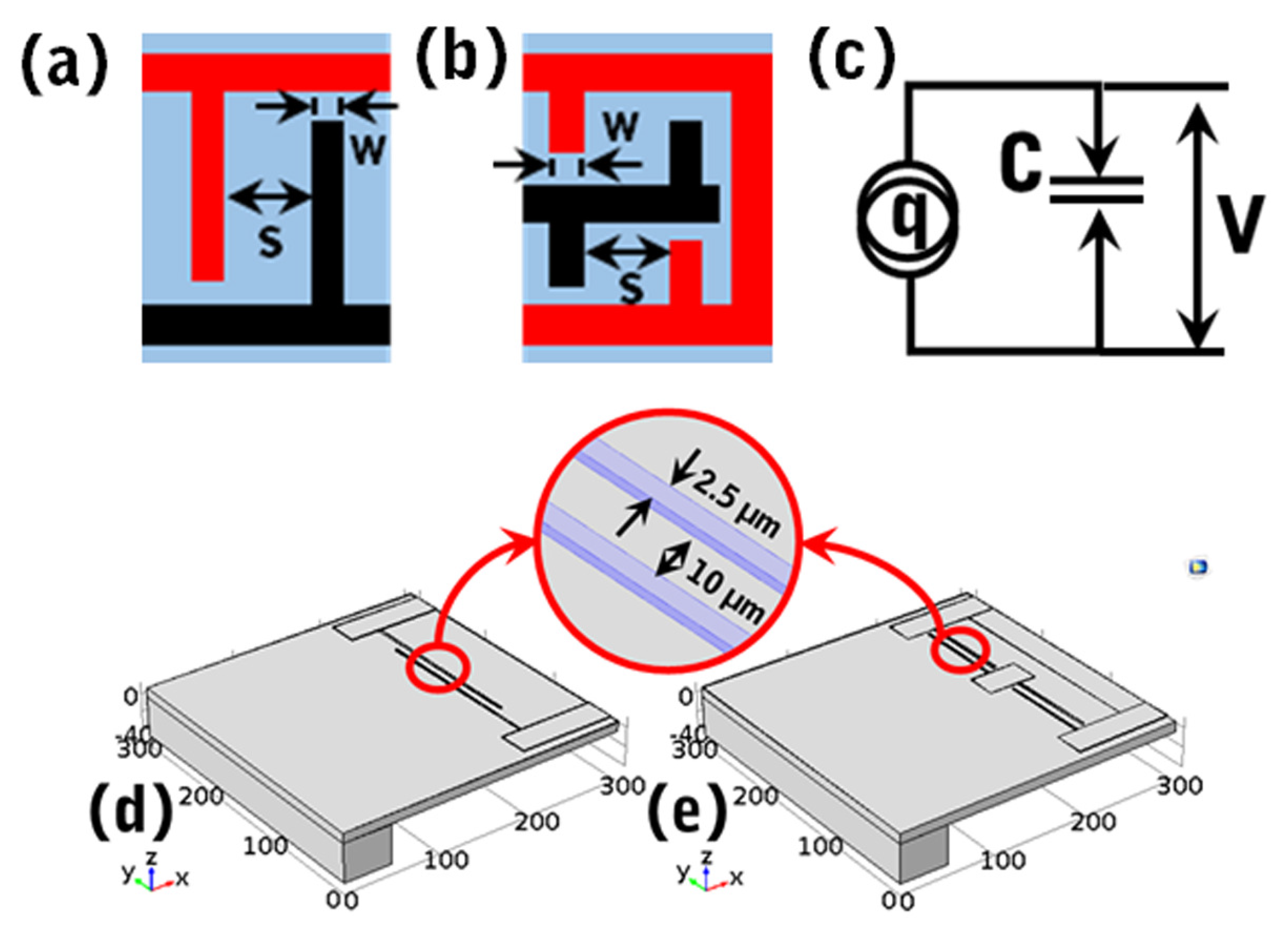
Figure 1a shows a unit cell of the regular D33 mode, which includes a pair of IDTs which are connected inter-digitally at MEs. Figure 1b shows the schematics of a unit cell of the proposed D33 mode. It includes three MEs, where two MEs are coupled and the other is placed in-between the coupled MEs with an equal inter-distance and different polarities. As a result, the coupled MEs form a uniform potential difference with the middle ME. After that, IDTs are patterned with an equal spacing, width and length.
In both models, the sensitivity (V/Pa) forms of the external mechanical stimuli (i.e., 1 Pa sound pressure) can be analyzed following the piezoelectric circuit model [17,19]. Figure 1c shows a circuit model which includes the induced charge (q), blocking capacitance (C) and induced voltage (V). The relationship of these parameters is given in [17,18],
where , , E, A, , , , w, W, l, L and s are the piezoelectric constant, induced strain, electric field, active area, area of electrode spacing, area of ME, area of IDT, width of IDT, width of main electrode, length of IDT, length of main electrode and spacing, respectively. Furthermore, is the effective material properties in 3–3 conditions and can be defined as the ratio of displacement to the electric field. In addition, i represents the number of unit cells, from 1 to N. Equation (1) suggests that the increasing of the IDTs and their spacing minimizes the capacitance, which enhances the sensitivity. This enhancement can be done by simply adding IDTs to the regular D33 mode, but it is necessary to have increased diaphragm dimensions. Moreover, the use of coupling does not require the device dimensions to be increased due to its orientation, which shows the significance of the proposed D33 mode. Besides, the use of a coupled D33 mode has some advantages over the regular D33 mode; for example, (1) it requires fewer fabrication steps in comparison with the double-layered D33 mode, and as a result it is cost-effective [24], and (2) the shared IDTs of the middle electrode do not interact with each other due to them having the same polarity—instead, they have a uniform potential difference with coupled edge electrodes.
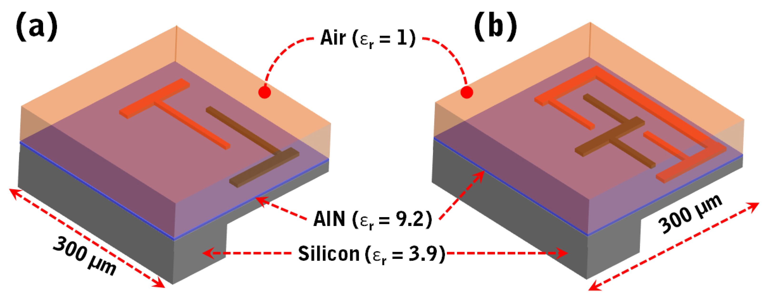
To understand the effectiveness of the coupled D33 modes, both modes (Figure 1a,b) were modeled with regard to their acoustic–piezoelectric interaction using the finite element method (FEM) with COMSOL Multiphysics 5.2 version software, and electrical performances were simulated by applying 1 Pa of sound pressure at 1 kHz frequency in a frequency domain study. In both models, the ME and IDT were made of 1.02 µm thick aluminum (with a Young’s modulus of 70 GPa, speed of sound of 6320 m/s and Poisson’s ratio of 0.35) and created on top of a 0.5 µm thick aluminum nitride (AlN) structure. The AlN (with a Young’s modulus of 273 GPa, speed of sound of 5760 m/s and Poisson’s ratio of 0.23) and aluminum structures along with their thicknesses were recommended by the PiezoMUMPs [25] since the authors fabricated the devices using multi-user MEMS processes (MUMPs), as discussed in Section 3.
On the other hand, the width (w) of each IDT and the spacing between IDTs were 2.5 µm and 10 µm, respectively, as used by Kim et al. [19], whereas the IDT’s length in the regular D33 mode was 200 µm; in the proposed D33 mode, this was reduced to 90 µm to make space for the middle ME as shown in Figure 1d,e. Both unit cells were modeled on a 300 µm × 300 µm diaphragm of a 10 µm thick silicon (with aYoung’s modulus of 130 GPa, speed of sound of 8433 m/s and Poisson’s ratio of 0.28). The diaphragm was fixed from the left side by making a 40 µm × 300 µm anchor. Then, following Kim et al. [19], each modeled unit cell was covered by an air medium with 300 µm × 300 µm dimensions with a 50 µm thickness as shown in Figure 2a,b, respectively, for unit cells of regular and proposed D33 modes.
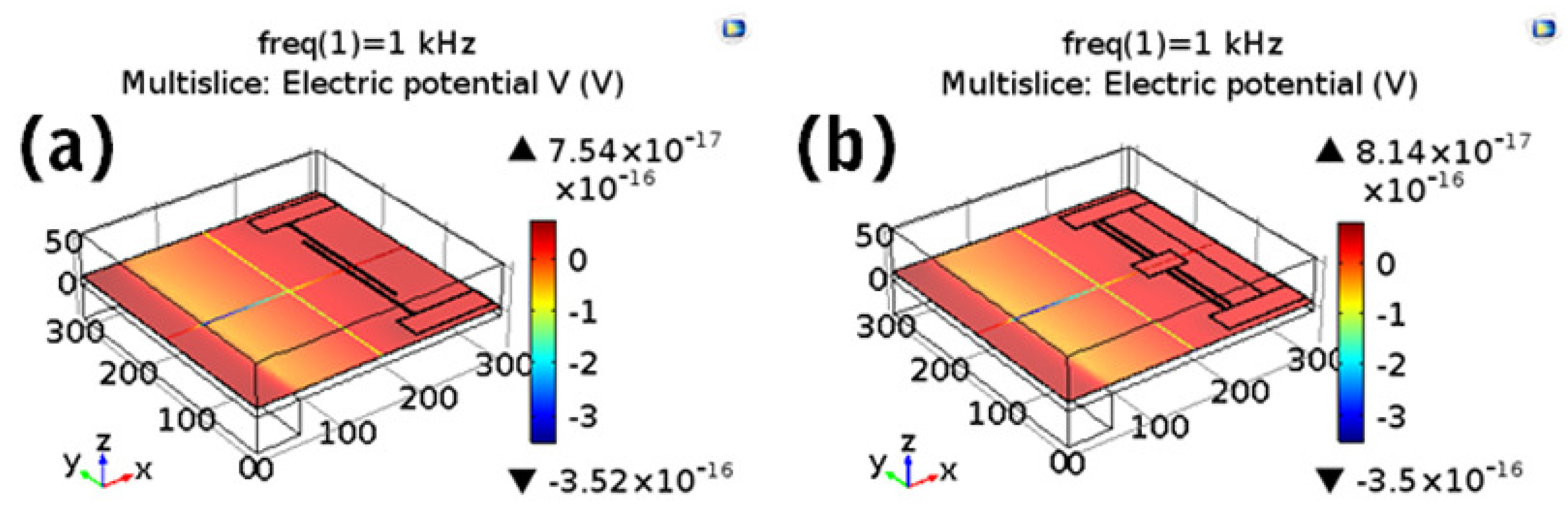
Under the physics-controlled meshing, the simulated sensitivity under the application of 1 Pa of sound pressure at 1 kHz frequency is shown in Figure 3a,b, respectively, for the regular and proposed D33 modes. The unit cell of the proposed D33 mode showed a 7.96% enhanced sensitivity compared to the regular D33 mode.
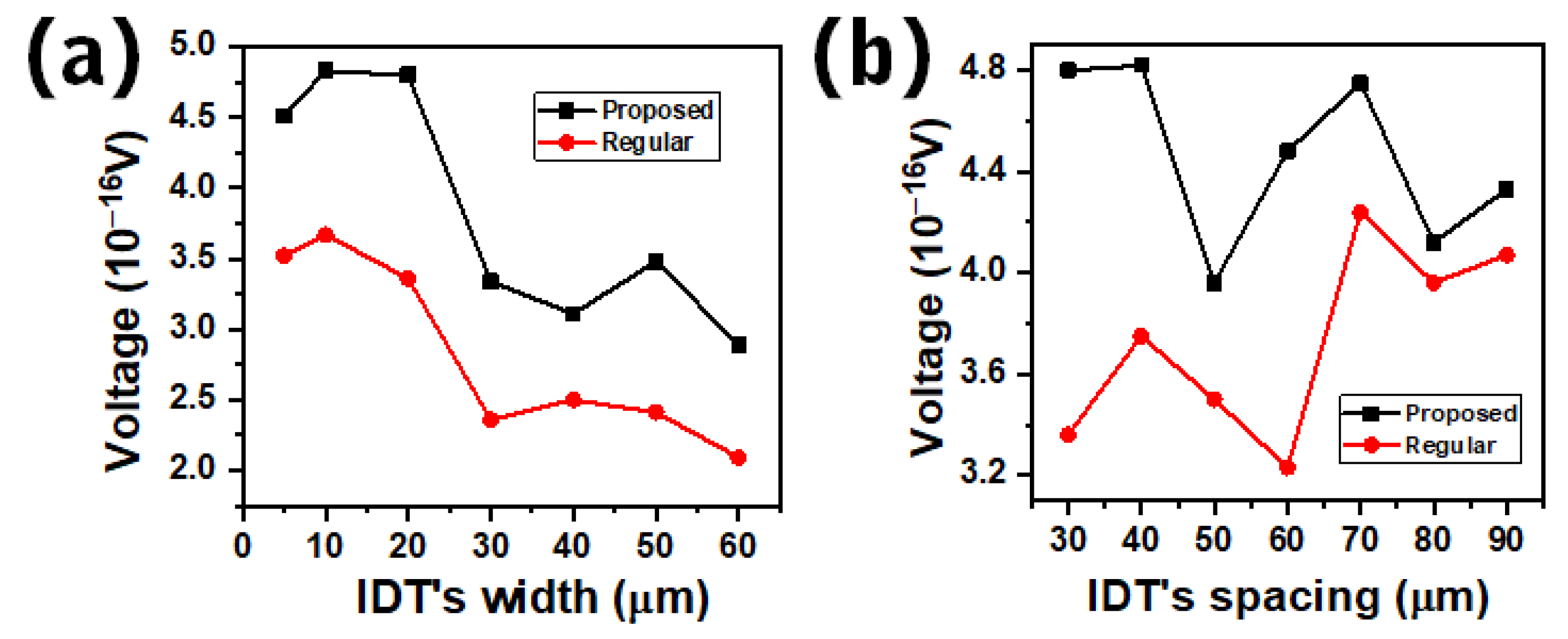
Both unit cells were simulated using the parameter taken from [19]. Thus, a further simulation was performed by varying the parameters of the IDTs to understand the effectiveness of the proposed D33 mode. To do that, a parametric sweep study was performed by varying the width of the IDT from 5 µm to 60 µm and the spacing between the IDTs from 30 µm to 90 µm. In the simulations, both unit cells from Figure 2a,b were used. Figure 4a shows the comparison between the unit cells of regular and proposed D33 modes, where the simulations were performed by varying the width of the IDT. It can be noticed that the unit cell of the proposed D33 mode constantly showed a higher voltage than the regular D33 mode. Then, the parametric sweep study was performed for spacing between IDTs from 30 µm to 90 µm. As shown in Figure 4b, the unit cell of the proposed D33 mode gave constantly higher responses than the regular D33 mode over a wide range of spacings. Moreover, in both simulations, the local minimum voltage occurred due to the ratio of the width and spacing (Figure 4a) [22] and the ratio of the spacing over the thickness of the whole diaphragm (for Figure 4b). Besides, the presence of the strain in the sensitivity formula presented in Equation (1) was simulated and shown in Figure S1a,b, respectively, for the unit cells of the regular and proposed D33 modes. The unit cell of the proposed D33 mode showed a 1.96% enhancement in strain over the regular D33 mode. Furthermore, the elastic strain energy (J) was also enhanced by 6.09%, as shown in Figure S1c,d. Along with the elastic strain, the displacement of the proposed D33 mode was enhanced by 3.32% as shown in Figure S1e,f. Nevertheless, the current density (A/m) showed a 15.9% decrease as compared to the regular D33 mode due to the minimized capacitance as shown in Figure S2a,b. Moreover, the enhanced electric potential (V) and charge (q)—followed by enhanced strain—showed a 5.9% enhancement of electric energy (E) by, E= V × q [26] as shown in Figure S2c,d.
3. Device Description
The understanding of the parametric sweep study implies that a unit cell with a 20 µm width of the IDT and a 70 µm spacing between IDTs results in a higher sensitivity response. Owing to these parameters, an MEMS directional microphone inspired by the ears of the fly Ormia ochracea was developed for experimental validations.
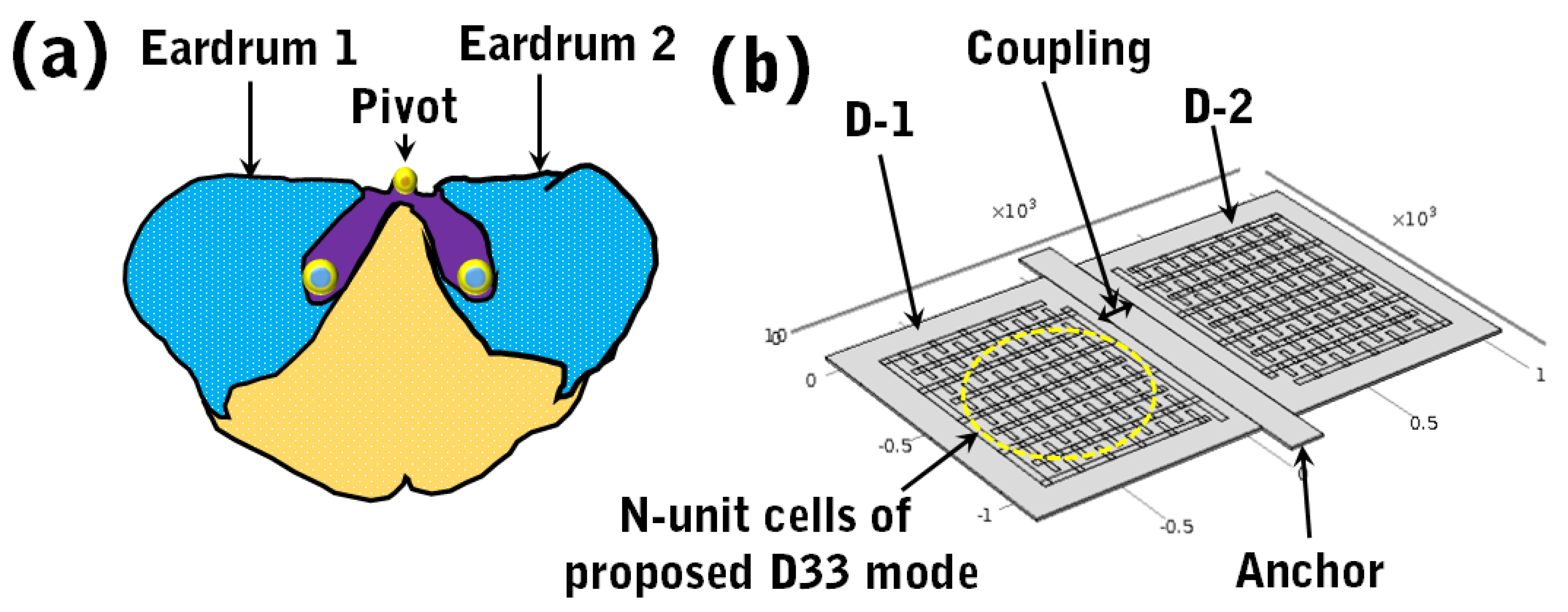
As previously mentioned (in Section 1), the hearing organ of the fly Ormia ochracea combines two eardrums—eardrum-1 and eardrum-2—as shown in Figure 5a [7,8,23]. Inspired by the hearing mechanism of the fly Ormia ochracea, Figure 5b shows the modeling of a MEMS directional microphone, where eardrum-1 and eardrum-2 were replaced with diaphragm-1 (D-1) and diaphragm-2 (D-2), respectively. Both diaphragms were coupled from the middle by imitating the fly’s hearing organ, as shown in Figure 5a. The whole device was supported by a pair of flexible torsional beams from both sides (marked as anchors in Figure 5b). On top of each individual diaphragm, the N-unit cells of the proposed D33 mode were patterned so that they could convert the mechanical deflection mode of the applied stimuli into the electrical signal; i.e., sensitivity.
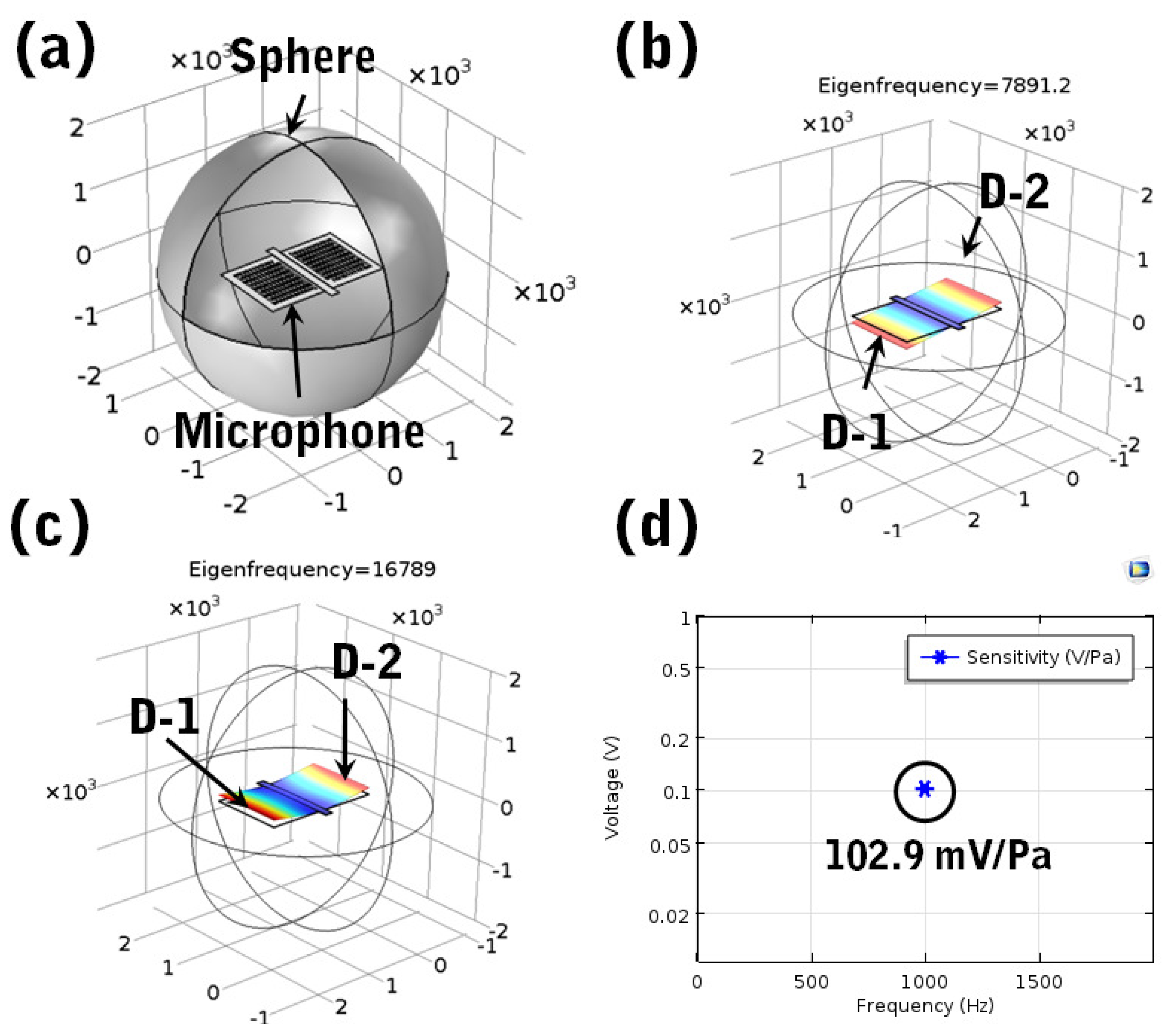
In a sound medium, the diaphragms rotates, and due to coupling, the diaphragm close to the sound source shows a phase difference from the other diaphragm. The phase difference governs the directional sensing cues, such as ITD and IID in audible frequencies. As a result, the directionality of this kind of directional microphone does not rely on a specific frequency in comparison with the stereo omnidirectional configurations. Moreover, at two resonant frequencies, such as in the rocking mode and bending mode, this kind of directional microphone achieves the best performance due to the amplified directional cues. The resonant frequencies were simulated in terms of the acoustic–piezoelectric interaction with the COMSOL Multiphysics software. To do that, the device shown in Figure 5b was modeled in COMSOL and covered by a sphere of a 2000 µm radius as shown in Figure 6a. Then, 1 Pa of sound pressure was applied from the left side (near to the diaphragm-1), and the eigenfrequencies, such as the rocking mode due to the out-of phase position of diaphragms, shown in Figure 6b, and the bending mode due to the in-phase position of diaphragms, shown in Figure 6c, were simulated.
After simulating the resonant frequencies, the electrical circuit from AC/DC physics connecting the measuring device’s gain as parallel resistance (R) was added to simulate the sensitivity. Under the frequency domain study, 1 Pa of sound pressure was applied at 1 kHz frequency to comply with the standard measurement of the sensitivity. The induced sensitivity was plotted across the parallel resistance, as shown in Figure 6d.
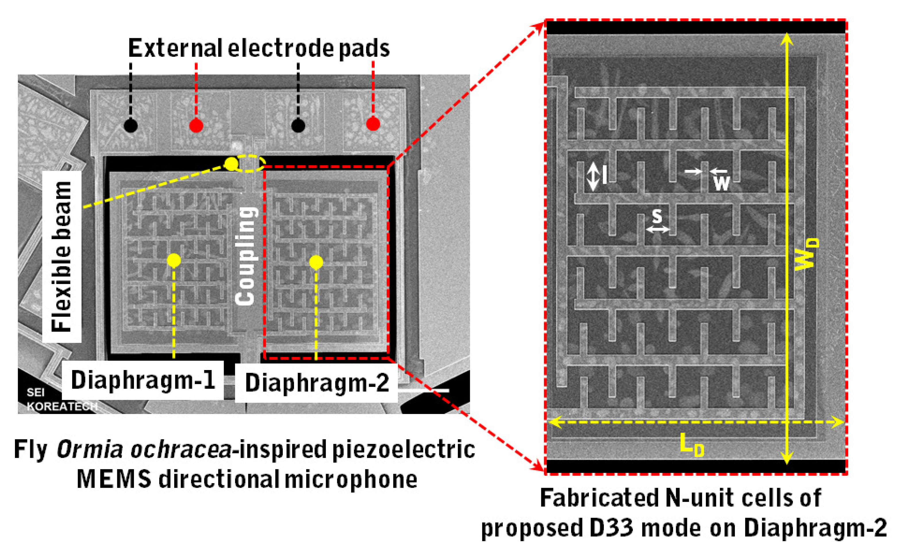
With satisfactory simulation results, the designed device was fabricated using multi-user MEMS processes (MUMPs); i.e., the PiezoMUMPs of MEMSCAP Inc., Durham, NC, United States [25]. Figure 7 shows the fabricated bio-inspired piezoelectric MEMS directional microphone which included two symmetric diaphragms, denoted as diaphragm-1 and diaphragm-2. Both diaphragms were coupled by imitating the hearing mechanism of the ears of the fly Ormia ochracea [7]. On top of each diaphragm, the N-unit cells of proposed D33 mode were fabricated to convert the mechanical motion of the diaphragm into the electrical signal, as shown in the inset of Figure 7.
4. Results and Discussion
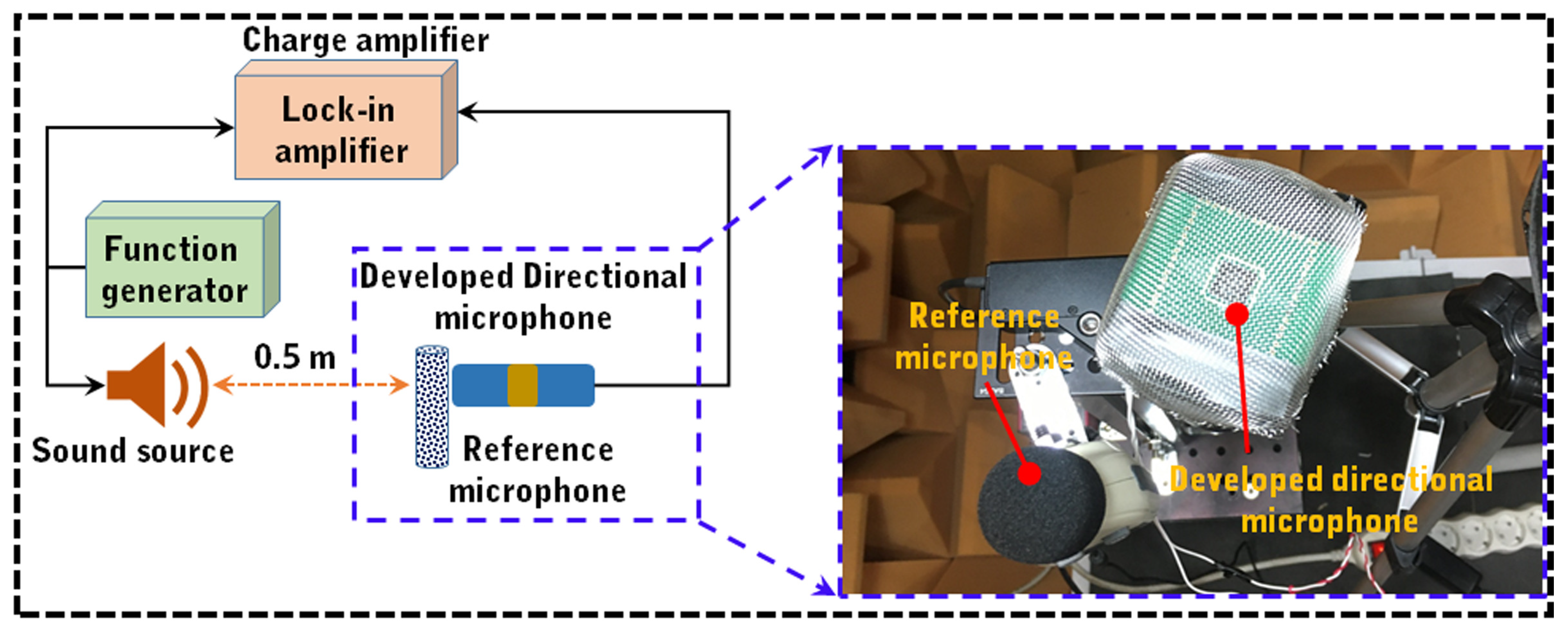
The experimental measurements were performed in an anechoic chamber using the setup shown in Figure 8. This included a reference microphone (GM1351, digital sound-level meter) to calibrate the incoming sound, a lock-in amplifier (SR830, Stanford Research Systems, Sunnyvale, CA, United States) for data recording, a function generator (DS345, Stanford Research Systems, Sunnyvale, CA, United States) to produce frequency-dependent sound and a speaker to emit the produced sound. The inset of Figure 8 shows the real view of the microphone in the anechoic chamber. The details of this setup can be found in our previous work [8].
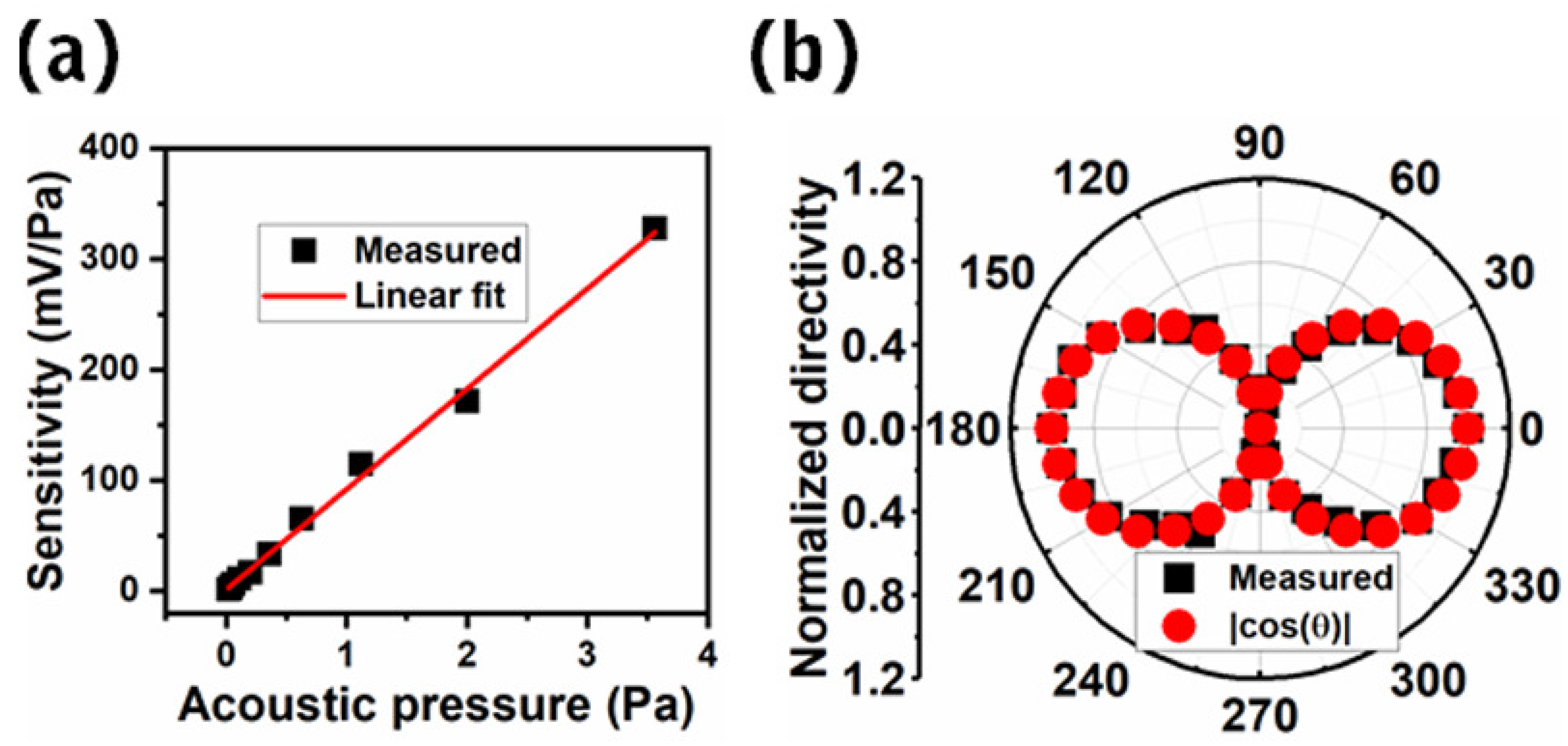
In the experimental measurements, the measured sensitivity at 1 kHz frequency and 1 Pa/94 dB of sound pressure level (SPL) sound pressure was found to be 110.46 mV/Pa considering the entire microphone. The measured sensitivity deviated by 6.8% in comparison with the simulated sensitivity, as shown in Figure 6d. Moreover, the deviation could be the reason for the fabrication tolerance as well as the mismatch of the positioning of the sound source relative to the microphone. In comparison with other D33 mode-based works, the measured sensitivity was ∼876 times higher than the double-layered D33 mode from 126.21 µV/Pa to 110.46 mV/Pa [24] and ∼7.36 times higher than distributed D33 mode 15 mV/Pa to 110.46 mV/Pa [27]. Moreover, the measurement was extended by varying the acoustic pressure from 0.02 Pa/60 dB SPL to 3.56 Pa/105 dB SPL, and the responses were found to be linear from 1.61 mV at 60 dB SPL to 327.78 mV at 105 dB SPL, as shown in Figure 9a. Taking this one step further, the noise of the microphone was found to be 0.03 mV at 1 kHz frequency and 0 dB of sound pressure, which led to a 71.32 dB signal-to-noise ratio (SNR) together with a sensitivity of 110.46 mV/Pa. The measured results showed a ∼32 and ∼1.042 times higher sensitivity and SNR, respectively, compared to the regular D33 mode based on our previous work [8]. Furthermore, the self-noise at 1 kHz frequency was reduced by 11.13% from 25.52 dB SPL to 22.68 dB SPL due to the improved sensitivity and SNR [8].
Figure 9b shows the directional sensitivity (i.e., directionality) of the fabricated bio-inspired piezoelectric MEMS directional microphone with the coupled D33 mode. In the measurements, the fabricated device was placed horizontally on a rotation stage (shown in Figure 8) which provided the flexibility to rotate the whole setup in the azimuth plane from 0 to 360. At each rotation, the responses of both diaphragms were measured and summed [8,23]. On the other hand, the formation of the directionality of this kind of directional microphone follows the in–plane directivity and/or cosine dependency [8,23]; as a result, the ideal pressure-gradient formula corresponding to P × cos() (where P and are the sound pressure and angular rotation of incoming sound, respectively) was used for comparison with the normalized measured response. Moreover, the normalization of the directionality was performed using the maximum response (110.46 mV/Pa) at 0/180 and minimum response (102.91 mV/Pa) at 90/270 followed by the results found for this kind of microphone [28]. Moreover, the measured directionality showed full compliance with the ideal-pressure gradient sensor, as shown in Figure 9b, and could be extended towards the localization of the incoming sound.
In summary, the primary intent of this study was not to describe an optimized D33 mode but rather to present a way of coupling the D33 mode. Due to the coupling, the proposed D33 mode uses the maximum effective area compared with the regular D33 mode. As a result, the proposed D33 mode is capable of transducing a high amount to the mechanical deflection of the diaphragm caused by the applied mechanical stimuli. The higher electrical sensitivity results in higher acoustic sensitivity, as the acoustic sensitivity is a linear product of the mechanical and electrical sensitivities. Owing to this fact, two unit cells of regular and proposed D33 modes were simulated by reflecting the piezoelectric circuit model, as presented in Equation (1).
With satisfactory simulation results, the unit cells of the regular and proposed D33 modes were simulated by varying the parameters of the IDT structure. The parameters with the highest induced voltage were used in a bio-inspired piezoelectric MEMS directional microphone for the experimental validations. Before fabricating the device, a comprehensive simulation was adopted to understand the effectiveness of the proposed D33 mode. The designed device with N-unit cells of the proposed D33 mode was simulated with the electrical circuit physics of COMSOL. Due to the use of N-unit cells of the proposed D33 mode, the whole diaphragm of the developed directional microphone was covered by them; as a result, the proposed D33 mode resulted in higher electrical sensitivity. The improved electrical sensitivity enhanced the acoustic sensitivity of the developed device.
In the experimental validations, the measured sensitivity was found to be in compliance with the simulated sensitivity. Taking this one step-further, the backside of the developed directional microphone was open; as a result, the device’s directionality allowed it to be described with the ideal pressure-gradient sensor [13]. Owing to this fact, the developed device showed fully compliant directionality by varying the incidence angle of the incoming sound, in contrast to the ideal pressure-gradient sensor.
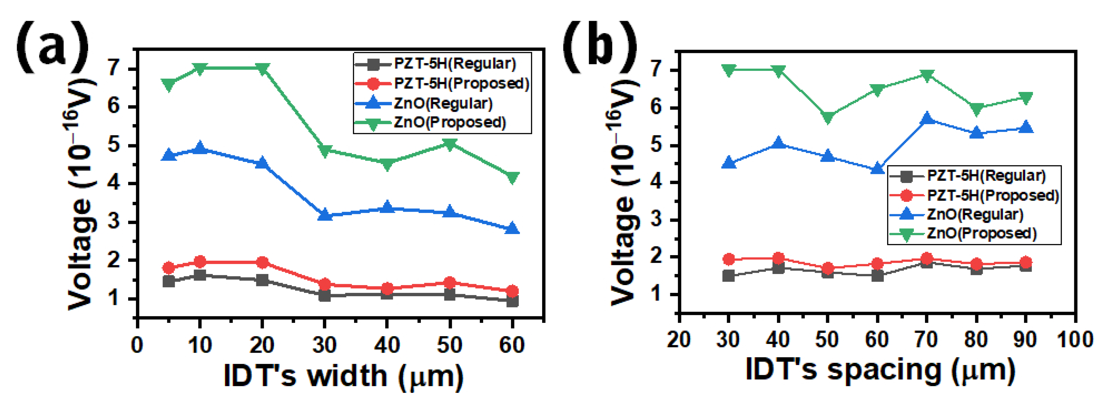
Moreover, due to the lack of fabrication facilities, the authors had to fabricate the device using multi-user MEMS processes (MUMPs) and validate the uniqueness of the proposed D33 mode using their recommended piezoelectric material (i.e., AlN). To understand how the proposed D33 mode performed with other piezoelectric materials, such as PZT-5H and zinc oxide (ZnO), we simulated the unit cells of regular and proposed D33 modes, as shown in Figure 2a,b, with varying ITD widths from 5 µm to 60 µm and spacings between IDTs from 30 µm to 90 µm. In these simulations, at first, the AlN was replaced with PZT-5H and then with ZnO. The simulated results are shown in Figure 10a,b, respectively, for the variation of the width of IDTs and the spacings between IDTs. In both results, the unit cells of the proposed D33 mode showed higher performance than that achieved by the unit cells of the regular D33 mode. The PZT-5H based simulations showed worse performance than ZnO, which was due to the ferroelectric properties of PZT as discussed in Section 1. However, the ZnO did not show ferroelectric properties at room temperature.
In conclusion, the acoustic functionalities demonstrated in this paper showed substantial improvements compared to the literature regarding the rigid diaphragm and D33 mode-based piezoelectric microphones. The improved characteristics of the developed bio-inspired piezoelectric MEMS directional microphone can be useful for applications n virtual reality for positioning and readjusting cameras. However, to do that, the present study should be extended by using advanced experimental measurements, such as frequency response, noise analysis and the realization of sound source localization, which is proposed as the future work.
Supplementary Materials
The following are available online at https://0-www-mdpi-com.brum.beds.ac.uk/2076-3417/11/3/1305/s1, Figure S1: FEM COMSOL simulated results, (a) first principal strain of the unit cell of regular D33 mode, (b) first principal strain of the unit cell of proposed D33 mode, (c) elastic strain energy (J) of the unit cell of regular D33 mode, (d) elastic strain energy (J) of the unit cell of proposed D33 mode, (e) displacement of the unit cell of regular D33 mode, and (f) displacement of the unit cell of proposed D33 mode. Figure S2: FEM COMSOL simulated results, (a) current density of the unit cell of regular D33 mode, (b) current density of the unit cell of proposed D33 mode, (c) total electric energy of the unit cell of regular D33 mode, and (d) total electric energy of the unit cell of proposed D33 mode.
Author Contributions
Conceptualization, A.R. and B.K.; methodology, A.R.; software, A.R.; validation, A.R., H.J. and B.K.; formal analysis, A.R.; investigation, A.R.; resources, A.R.; data curation, A.R.; writing—original draft preparation, A.R.; writing—review and editing, A.R., B.K. and H.J.; visualization, A.R.; supervision, B.K.; project administration, B.K.; funding acquisition, B.K. All authors have read and agreed to the published version of the manuscript.
Funding
This work was supported by Grant NRF–2018R1A6A1A03025526 under the Priority Research Program through the National Research Foundation of Korea (NRF) under the Ministry of Education.
Institutional Review Board Statement
Ethical review and approval were not application for studies not involving humans or animals.
Informed Consent Statement
Informed consent was not application for studies not involving humans.
Data Availability Statement
The supporting information of this manuscript has been submitted, and extended data are made available upon reasonable request from the corresponding author.
Acknowledgments
The authors thank the Cooperative Equipment Center at Korea University of Technology and Education for assistance with scanning electron microscopy.
Conflicts of Interest
The authors declare that they have no conflict of interest.
Sample Availability
The simulated/original data for this study are available from the corresponding author on reasonable request.
Abbreviations
The following abbreviations are used in this manuscript:
| VR | Virtual reality |
| MEMS | Microelectromechanical system |
| MUMPs | Multi-user MEMS processes |
| SNR | Signal-to-noise ratio |
| MPE | Multi-projected environment |
| IDT | Inter-digitated electrode |
| ME | Main electrode |
| SPL | Sound pressure level |
References
- Zheng, J.; Chan, K.; Gibson, I. Virtual reality. IEEE Potentials 1998, 17, 20–23. [Google Scholar] [CrossRef]
- Choo, H.; Tommelein, I. Database Synchronization Technology for Multi-Project Schedule Coordination, NIST SPECIAL PUBLICATION SP 2003. pp. 109–116. Available online: http://citeseerx.ist.psu.edu/viewdoc/summary?doi=10.1.1.533.9815 (accessed on 10 December 2020).
- Zhao, S.; Ahmed, S.; Liang, Y.; Rupnow, K.; Chen, D.; Jones, D.L. A real-time 3D sound localization system with miniature microphone array for virtual reality. In Proceedings of the 2012 7th IEEE Conference on Industrial Electronics and Applications (ICIEA), Singapore, 18–20 July 2012; pp. 1853–1857. [Google Scholar]
- Dong, M.; Wang, H.; Guo, R. Towards understanding the differences of using 3d auditory feedback in virtual environments between people with and without visual impairments. In Proceedings of the 2017 IEEE 3rd VR Workshop on Sonic Interactions for Virtual Environments (SIVE), Los Angeles, CA, USA, 19 March 2017; pp. 1–5. [Google Scholar]
- Hu, J.; Mo, Q.; Liu, Z. Multi-Source Classification: A DOA-Based Deep Learning Approach. In Proceedings of the 2020 International Conference on Computer Engineering and Application (ICCEA), Guangzhou, China, 18–20 March 2020; pp. 463–467. [Google Scholar]
- Miles, R. Comparisons of the Performance of Knowles Hearing aid Microphones to that of the Binghamton Ormia-Inspired Gradient Microphone; Technical Report; State University of New York at Binghamton: Binghamton, NY, USA, 2015; Available online: http://0-dx-doi-org.brum.beds.ac.uk/10.13140/RG.2.2.17566.95043 (accessed on 10 December 2020).
- Miles, R.; Robert, D.; Hoy, R. Mechanically coupled ears for directional hearing in the parasitoid fly Ormia ochracea. J. Acoust. Soc. Am. 1995, 98, 3059–3070. [Google Scholar] [CrossRef] [PubMed]
- Rahaman, A.; Kim, B. Sound source localization by Ormia ochracea Inspired Low- Piezoelectric MEMS Dir. Microphone. Sci. Rep. 2020, 10, 1–10. [Google Scholar]
- Yoo, K.; Yeh, J.L.; Tien, N.; Gibbons, C.; Su, Q.; Cui, W.; Miles, R. Fabrication of a biomimetic corrugated polysilicon diaphragm with attached single crystal silicon proof masses. In Transducers’ 01 Eurosensors XV; Springer: Berlin/Heidelberg, Germany, 2001; pp. 130–133. [Google Scholar]
- Miles, R.; Su, Q.; Cui, W.; Shetye, M.; Degertekin, F.; Bicen, B.; Garcia, C.; Jones, S.; Hall, N. A low-noise differential microphone inspired by the ears of the parasitoid fly Ormia ochracea. J. Acoust. Soc. Am. 2009, 125, 2013–2026. [Google Scholar] [CrossRef] [PubMed] [Green Version]
- Liu, H.; Chen, Z.; Yu, M. Biology-inspired acoustic sensors for sound source localization. In Proceedings of the Sensors and Smart Structures Technologies for Civil, Mechanical, and Aerospace Systems 2008, San Diego, CA, USA, 8 April 2008; 6932, p. 69322Y. [Google Scholar]
- Liu, H.; Currano, L.; Gee, D.; Helms, T.; Yu, M. Understanding and mimicking the dual optimality of the fly ear. Sci. Rep. 2013, 3, 1–6. [Google Scholar] [CrossRef] [PubMed] [Green Version]
- Touse, M.; Sinibaldi, J.; Simsek, K.; Catterlin, J.; Harrison, S.; Karunasiri, G. Fabrication of a microelectromechanical directional sound sensor with electronic readout using comb fingers. Appl. Phys. Lett. 2010, 96, 173701. [Google Scholar] [CrossRef]
- Kuntzman, M.L.; Gloria Lee, J.; Hewa-Kasakarage, N.N.; Kim, D.; Hall, N.A. Micromachined piezoelectric microphones with in-plane directivity. Appl. Phys. Lett. 2013, 102, 054109. [Google Scholar] [CrossRef] [PubMed]
- Rahaman, A.; Ishfaque, A.; Jung, H.; Kim, B. Bio-inspired rectangular shaped piezoelectric MEMS directional microphone. IEEE Sens. J. 2018, 19, 88–96. [Google Scholar] [CrossRef]
- Zhang, Y.; Bauer, R.; Jackson, J.C.; Whitmer, W.M.; Windmill, J.F.; Uttamchandani, D. A low-frequency dual-band operational microphone mimicking the hearing property of Ormia ochracea. J. Microelectromech. Syst. 2018, 27, 667–676. [Google Scholar] [CrossRef] [Green Version]
- Rahaman, A.; Ishfaque, A.; Kim, B. Effect of torsional beam length on acoustic functionalities of bio-inspired piezoelectric MEMS directional microphone. IEEE Sens. J. 2019, 19, 6046–6055. [Google Scholar] [CrossRef]
- Jia, Y.; Seshia, A.A. Five topologies of cantilever-based MEMS piezoelectric vibration energy harvesters: A numerical and experimental comparison. Microsyst. Technol. 2016, 22, 2841–2852. [Google Scholar] [CrossRef] [Green Version]
- Kim, D.; Hewa-Kasakarage, N.N.; Hall, N.A. A theoretical and experimental comparison of 3-3 and 3-1 mode piezoelectric microelectromechanical systems (MEMS). Sens. Actuators A Phys. 2014, 219, 112–122. [Google Scholar] [CrossRef] [Green Version]
- Rahaman, A.; Park, C.H.; Kim, B. Design and characterization of a MEMS piezoelectric acoustic sensor with the enhanced signal-to-noise ratio. Sens. Actuators A Phys. 2020, 311, 112087. [Google Scholar] [CrossRef]
- Kim, S.B.; Park, H.; Kim, S.H.; Wikle, H.C.; Park, J.H.; Kim, D.J. Comparison of MEMS PZT cantilevers based on d_{31} and d_{33} modes for vibration energy harvesting. J. Microelectromech. Syst. 2012, 22, 26–33. [Google Scholar] [CrossRef]
- Kim, S.B.; Park, J.H.; Kim, S.H.; Ahn, H.; Wikle, H.C.; Kim, D.J. Modeling and evaluation of d33 mode piezoelectric energy harvesters. J. Micromech. Microeng. 2012, 22, 105013. [Google Scholar] [CrossRef]
- Rahaman, A.; Kim, B. Sound source localization in 2D using a pair of bio-inspired MEMS directional microphones. IEEE Sens. J. 2020, 21, 1369–1377. [Google Scholar] [CrossRef]
- Shen, Z.; Lu, J.; Tan, C.W.; Miao, J.; Wang, Z. d33 mode piezoelectric diaphragm based acoustic transducer with high sensitivity. Sens. Actuators A Phys. 2013, 189, 93–99. [Google Scholar] [CrossRef]
- Cowen, A.; Hames, G.; Glukh, K.; Hardy, B. PiezoMUMPs Design Handbook; MEMSCAP Inc.: Durham, NC, USA, 2014; Volume 1. [Google Scholar]
- Igreja, R.; Dias, C. Analytical evaluation of the interdigital electrodes capacitance for a multi-layered structure. Sens. Actuators A Phys. 2004, 112, 291–301. [Google Scholar] [CrossRef]
- Kashyap, R.; Lenka, T.R.; Baishya, S. Distributed Parameter Modeling of Cantilevered-d_{33}-Mode Piezoelectric Energy Harvesters. IEEE Trans. Electron Devices 2016, 63, 1281–1287. [Google Scholar] [CrossRef]
- Kuntzman, M.L.; Hall, N.A. Sound source localization inspired by the ears of the O rmia ochracea. Appl. Phys. Lett. 2014, 105, 033701. [Google Scholar] [CrossRef]
Figure 1.
Modeling of D33 mode, (a) unit cell of regular D33 mode, (b) unit cell of proposed D33 mode, (c) equivalent piezoelectric circuit of a unit cell of the regular and proposed D33 modes, (d) computer-assisted design (CAD) modeling of unit cell of the regular D33 mode and (e) CAD modeling of a unit cell of the proposed D33 mode.

Figure 2.
Modeling of unit cells in terms of the acoustic–piezoelectric interaction with the finite element method (FEM) in COMSOL: (a) unit cell of regular D33 mode, and (b) unit cell of proposed D33 mode.
Figure 2.
Modeling of unit cells in terms of the acoustic–piezoelectric interaction with the finite element method (FEM) in COMSOL: (a) unit cell of regular D33 mode, and (b) unit cell of proposed D33 mode.

Figure 3.
FEM COMSOL simulated results: (a) voltage of unit cell of the regular D33 mode, and (b) voltage of unit cell of the proposed D33 mode.
Figure 3.
FEM COMSOL simulated results: (a) voltage of unit cell of the regular D33 mode, and (b) voltage of unit cell of the proposed D33 mode.

Figure 4.
FEM COMSOL-simulated results of unit cells of regular and proposed D33 modes: (a) varying IDT widths, and (b) varying the spacing between two adjacent IDTs with a 20 µm width.
Figure 4.
FEM COMSOL-simulated results of unit cells of regular and proposed D33 modes: (a) varying IDT widths, and (b) varying the spacing between two adjacent IDTs with a 20 µm width.

Figure 5.
Bio-inspired piezoelectric microelectromechanical system (MEMS) directional microphone, (a) schematic of the fly Ormia ochracea’s ear, redrawn from [8], and (b) directional microphone that imitates the fly Ormia ochracea’s ears.
Figure 5.
Bio-inspired piezoelectric microelectromechanical system (MEMS) directional microphone, (a) schematic of the fly Ormia ochracea’s ear, redrawn from [8], and (b) directional microphone that imitates the fly Ormia ochracea’s ears.

Figure 6.
Device simulation, (a) modeling of the device in terms of the acoustic–piezoelectric interaction, (b) rocking mode at a frequency of 7891.2 Hz, (c) bending mode at a frequency of 16,789 Hz, and (d) sensitivity at 1 Pa of sound pressure and 1 kHz frequency.
Figure 6.
Device simulation, (a) modeling of the device in terms of the acoustic–piezoelectric interaction, (b) rocking mode at a frequency of 7891.2 Hz, (c) bending mode at a frequency of 16,789 Hz, and (d) sensitivity at 1 Pa of sound pressure and 1 kHz frequency.

Figure 7.
Scanning electron microscope (SEM) image of the fabricated bio-inspired piezoelectric MEMS directional microphone, where L and W are each individual diaphragm’s length (880 µm) and width (1200 µm), respectively. The inset shows the zoomed view of a single span of the proposed D33 mode, where s, w and l are the spacing (68 µm), width (20 µm), and length (90 µm) of IDT, respectively.

Figure 8.
Experimental setup in an anechoic chamber with a zoomed-in real view of the microphone setup.
Figure 8.
Experimental setup in an anechoic chamber with a zoomed-in real view of the microphone setup.

Figure 9.
Experimental results at 1 kHz frequency: (a) acoustic sensitivity of the microphone when varying the acoustic pressure from 0.02 Pa to 3.56 Pa at 1 kHz frequency, and (b) directivity measurements at 1 kHz frequency and 1 Pa of sound pressure.
Figure 9.
Experimental results at 1 kHz frequency: (a) acoustic sensitivity of the microphone when varying the acoustic pressure from 0.02 Pa to 3.56 Pa at 1 kHz frequency, and (b) directivity measurements at 1 kHz frequency and 1 Pa of sound pressure.

Figure 10.
FEM simulations of unit cells of the regular and proposed D33 modes using PZT-5H and ZnO, (a) with varying IDT widths in a range of 5 µm, 10 µm, 20 µm, 30 µm, 40 µm, 50 µm and 60 µm, and (b) with varying spacings between two adjacent IDTs in a range of 30 µm, 40 µm, 50 µm, 60 µm, 70 µm, 80 µm, and 90 µm at an IDT width of 20 µm.

Publisher’s Note: MDPI stays neutral with regard to jurisdictional claims in published maps and institutional affiliations. |
© 2021 by the authors. Licensee MDPI, Basel, Switzerland. This article is an open access article distributed under the terms and conditions of the Creative Commons Attribution (CC BY) license (http://creativecommons.org/licenses/by/4.0/).
Share and Cite
MDPI and ACS Style
Rahaman, A.; Jung, H.; Kim, B. Coupled D33 Mode-Based High Performing Bio-Inspired Piezoelectric MEMS Directional Microphone. Appl. Sci. 2021, 11, 1305. https://0-doi-org.brum.beds.ac.uk/10.3390/app11031305
AMA Style
Rahaman A, Jung H, Kim B. Coupled D33 Mode-Based High Performing Bio-Inspired Piezoelectric MEMS Directional Microphone. Applied Sciences. 2021; 11(3):1305. https://0-doi-org.brum.beds.ac.uk/10.3390/app11031305
Chicago/Turabian StyleRahaman, Ashiqur, Haeil Jung, and Byungki Kim. 2021. "Coupled D33 Mode-Based High Performing Bio-Inspired Piezoelectric MEMS Directional Microphone" Applied Sciences 11, no. 3: 1305. https://0-doi-org.brum.beds.ac.uk/10.3390/app11031305
Note that from the first issue of 2016, this journal uses article numbers instead of page numbers. See further details here.