
Energy Efficient Secure Communication Model against Cooperative Eavesdropper


1
School of Computer Science and Robotics, National Research Tomsk Polytechnic University, 634050 Tomsk, Russia
2
Faculty of Science and Technology, NOVA University Lisbon, 2829-516 Caparica, Portugal
3
Copelabs, Universidade Lusòfona, 1700-097 Lisbon, Portugal
4
Centre for Telecommunication Research, School of Engineering, Sri Lanka Technological Campus, Padukka City 10500, Sri Lanka
5
Instituto de Telecomunicações, 1049-001 Lisbon, Portugal
6
Instituto de Telecomunicações, Instituto Superior Técnico, Universidade de Lisboa, 1049-001 Lisbon, Portugal
*
Author to whom correspondence should be addressed.
Appl. Sci. 2021, 11(4), 1563; https://0-doi-org.brum.beds.ac.uk/10.3390/app11041563
Submission received: 14 January 2021
/
Revised: 31 January 2021
/
Accepted: 3 February 2021
/
Published: 9 February 2021
(This article belongs to the Special Issue Advances in Information and Communication Technologies (ICT))
Abstract
:In a wiretap channel system model, the jammer node adopts the energy-harvesting signal as artificial noise (jamming signal) against the cooperative eavesdroppers. There are two eavesdroppers in the wiretap channel: eavesdropper E1 is located near the transmitter and eavesdropper E2 is located near the jammer. The eavesdroppers are equipped with multiple antennas and employ the iterative block decision feedback equalization decoder to estimate the received signal, i.e., information signal at E1 and jamming signal at E2. It is assumed that E1 has the channel state information (CSI) of the channel between transmitter and E1, and similarly, E2 has the CSI of channel between jammer and E2. The eavesdroppers establish communication link between them and cooperate with each other to reduce the information signal interference at E2 and jamming signal interference at E1. The performance of decoders depends on the signal to interference plus noise ratio (SINR) of the received signal. The power of information signal is fixed and the power of the jamming signal is adjusted to improve the SINR of the received signal. This research work is solely focused on optimizing the jamming signal power to degrade the performance of cooperative eavesdroppers. The jamming signal power is optimized for the given operating SINR with the support of simulated results. The jamming signal power optimization leads to better energy conservation and degrades the performance of eavesdroppers.
1. Introduction
In an indoor wireless communication network (WCN), different types of network devices and sensors are employed within the network to share information for the purpose of automating multiple functions inside an indoor environment. This results in increased signal transmission and energy usage by the WCN [1,2]. In this article, we consider the presence of multiple eavesdroppers for the purpose of channel estimation and information estimation, and this leads to wiretap channel system models. Therefore, smart indoor WCN requires energy efficient secure communication and, therefore, green communication technologies, such as wireless power transfer (WPT), which can be adapted for physical layer security (PLS) [3]. High power signals can be used for WPT and other signal processing applications such as channel estimation [4,5] and as a jamming signal [6,7].
In a wiretap channel, by using artificial noise (AN), the jammer can degrade the signal to interference plus noise ratio (SINR) of the eavesdroppers [3]. In general, the secrecy rate of legitimate users in a wiretap channel are improved by degrading SINR eavesdroppers, as in [8,9], and by employing multiple-input and multiple-output (MIMO) system models, as in [10]. Contrary to SINR degradation at eavesdroppers, the jammer avoids SINR degradation at the legitimate receiver by introducing AN in the null space of the legitimate receiver’s channel matrix. Therefore, the jammer improves secrecy rate without compromising the quality of the legitimate users’ signal [11]. However, this is considered as a challenge in imperfect CSI condition [12]. Eavesdropper can reduce the impact of AN with the knowledge of channel state information (CSI) of the channel between jammer and receiver but, under normal circumstances, it is highly unlikely for the eavesdropper to have the CSI of the receiver to jammer channel link. Therefore, AN can be effectively used against many robust eavesdroppers, as in [13,14].
In our previous research work [6], the system model was considered to have a passive eavesdropper with high channel correlation to the legitimate receiver, which is considered as a major limitation of jammer in a wiretap channel. It is mitigated by increasing the jamming signal power that amplifies the error due to the difference in CSI between both channels. The increment in jamming signal power can degrade the eavesdropper’s signal to noise ratio (SNR), but this can also increase the negative impact of the jammer’s precoding error at legitimate receiver. The effect of the jammer’s precoding error at a legitimate receiver can be reduced by using the expected jammer’s precoding error as additional noise power feedback in the iterative block decision feedback equalization (IBDFE) decoder [6]. Even though the increase in jamming signal power can increase SNR degradation at the eavesdropper, this is not energy efficient and can degrade the performance of legitimate receiver, if there is any channel estimation error or precoding error in the legitimate network. In [6], the passive eavesdropper does not estimate jamming signal and in this research, the idea of cooperative eavesdropper is explored to estimate jamming signal. Therefore, it is necessary to optimize the jamming signal power and explore counter measures for a cooperative eavesdropper scenario.
In this research work, we consider that the eavesdropper can estimate the CSI between the eavesdropper and its the nearest node. With this assumption, we explore the limitation of a legitimate network to act against a robust MIMO cooperative eavesdropper network. There are several studies focused on optimum power allocation at jammer nodes and information transmitter nodes [3,15]. In [15], the power optimization of jamming signal based on CSI of legitimate receiver to save energy and avoid interference to the legitimate receiver based on its CSI. There are few research works that are focused on multiple eavesdropper scenarios in a wire-tap channel [16,17,18]. In [17], the eavesdroppers cooperate with each other to detect the information transmission between the transmitter and relays and do not consider detecting jamming signal to remove interference. In [18], the research work is focused on a scenario where multiple eavesdroppers decode information from the base station and the legitimate network with the help of multiple friendly jammers to degrade the SINR of the cooperative eavesdroppers. However, in our work, we consider that the MIMO eavesdropper is closer to the jammer and detects the jamming signal and cooperates with the eavesdropper nearer to the transmitter to estimate information. Thus, under these special circumstances, the research work is focused on hardware configuration and optimum power allocation for the jammer node. We consider that the eavesdropper employs MIMO IBDFE. IBDFE is an efficient low complex receiver, as compared to the non-iterative decoder [19,20] and it can be effectively used with single carrier frequency-division multiple access (SC-FDMA) transmission techniques [21,22].
In this article, we present an unique scenario in which one eavesdropper detects the jamming signal and another eavesdropper estimates the information signal, and then cooperate with each other to improve both jamming signal and information signal estimate. The SINR of improved jamming signal estimate and information signal estimate at the eavesdroppers is derived. The performance of the MIMO IBDFE receiver with the change in antenna configuration and the impact of change in the SNR of the jamming signal is analysed with the simulated results. The ratio between jamming signal power and information signal power for the given operating SNR is optimized with the support of simulated results. Furthermore, we make the system model more energy efficient by optimizing the power of the jamming signal.
The structure of the paper is as follows. The system model is explained in Section 2, the MIMO IBDFE equation is derived in Section 2.2 and the SINR equation for the cooperative eavesdropper is given in Section 2.3. The performances of the eavesdroppers are analyzed and the optimum jamming signal power for a given operating SNR is studied in Section 3. The conclusion is presented in Section 4.
Throughout this article, matrices or vectors are denoted by bold letters and scalar variables are denoted by italic letters. The variables associated to frequency domain and time domain are denoted by capital letters and small letters, respectively. , , , and denote the conjugate, transpose, Hermitian, trace and expectation operations, respectively. , and denote sample, hard decision and soft decision, respectively, and the appropriate Identity matrix of X is denoted as .
2. System Model
The system model consists of transmitter A, receiver B, jammer J, and eavesdroppers E1 and E2 in a wire tap channel. It is assumed that E1 is closer to A, while E2 is closer to J. A and B use a single input and single output antenna (SISO) system for information transmission and reception. B has an additional antenna for energy harvesting application. J uses the MIMO system for broadcasting jamming signals and it has a separate communication setup to find the location of B and to avoid jamming B. Eavesdroppers use the MIMO system model for receiving information and jamming signals. All the nodes in the system model experience Rayleigh frequency selective fading channels. The SISO channel link between A and B is denoted as , whereas the MIMO channel link between J and E1 is denoted as and, likewise, all the MIMO single inputs with multiple outputs and the multiple inputs with single output channel links are denoted by using and their respective nodes. is characterized as , where is the channel variance. It is assumed that the expected values of channel variances of all the channel links in the system model are equal. All communication nodes experience additive white Gaussian noise (AWGN) and are modeled as zero mean complex Gaussian random variables. AWGN, experienced by A, is denoted as and is characterized as , where is the noise variance. Similarly, AWGN is experienced by how all nodes are denoted and characterized. All the legitimate users and jammers are considered to have full channel knowledge. Eavesdroppers are considered to have the channel estimate of all the nodes and this channel estimate depends on the SNR at the eavesdropper node. The channel estimate and the channel estimation error of are denoted as and , respectively, where A is the transmitting node and E1 is the receiving node. In similar way, the channel estimate and channel estimation error of the channel between eavesdropper and remaining nodes are denoted. The SNR and SINR of the receiving node E1 are denoted as and , respectively. In a similar way, the SNR and SINR are denoted for all the receiving nodes. The SNR of the receiving node considers the power ratio between the received signal and AWGN in an AWGN channel and, therefore, SNR excludes fading coefficient. The SINR of the receiving node considers the power ratio between the received signal and the interference of other signal along with AWGN. The information signal from A, jamming signals from J are denoted as and . The distance between A and E1 is denoted as ; similarly, the distance between any two nodes in the system model is denoted. In general, the index of transmitting antennas and receiving antennas are denoted as t and r, respectively, where with T is denoted as the total number of transmitting antennas and , with R denoted as the total number of receiving antennas. The total number of transmitting antennas at J is denoted as . The total number of receiving antennas at E1 and E2 are denoted as and , respectively.
2.1. System Model Equations
The relationship between transmit power of jamming signal and information symbols is given as
The unamplified version of and are denoted as and , respectively. , where , are the unamplified version of modulated signals () transmitted from J. The transmit powers of and are denoted as and , respectively, where is the transmit power of single jamming signal stream and all the jamming signal streams are considered to have equal expected values. The ratio between the total transmit power of the Jamming signal and information signal is denoted as . The relationship between transmit SNR at A and J is given as
where . The received power of and at E1 and E2 are, respectively, given in the following equations and for the sake of simplicity, only the path loss factor is considered and the channel fading co-efficient is neglected. The received power of and at E1 are denoted as and , respectively. The received power of and at E2 are denoted as and , respectively. Then, the relationships between transmit power and received power at E1 and E2 are, respectively, given as
where and are denoted as the ratio between the total received power of jamming signal and information signal at E1 and E2, respectively. The received signal at B is given as
where denotes the null space vector of the precoded jamming signal for the respective channel link. The received signal at E1 is
where is considered as a noise term. The channel estimate error at E1 is given as , where represents the expected minimum mean square error function. In similar way, the channel estimates and the channel estimate errors of other channels are denoted. The SINR of are, respectively, given as
For the sake of simplicity, and are set to 1. The received signal at E2 is given as
where is considered as a noise term. The SINR of is given as
where the SINR of each jamming signal stream is estimated separately. For the sake of simplicity, and are considered as 1. and can be improved by reducing the signal interference.
We consider that E2 is closer to J and the information signal strength is lower than the jamming signal and, with this condition, by using IBDFE, the impact of signal interference can be reduced. The following section briefly explains IBDFE for MIMO model.
2.2. Iterative Block Decision Feedback Equalization Decoder
All the communicating nodes use the SC-FDMA transmission technique and the decoders use IBDFE. It is assumed that with perfect receiver synchronization for all antennas. The information symbol in the time and frequency domains are denoted as and , respectively, where x and X are the information symbol in time and frequency domain, n and k are the index of the symbol in time and frequency domain, respectively. The received signal in the time and frequency domains are denoted as and , respectively. The received signal in matrix format is denoted as and at the receiver is given as
where denotes the channel matrix with frequency. is AWGN with variance . The linear minimum mean square error (LMMSE) decision of from the IBDFE receiver is , which is given as
where and is assumed to be equal for all the values of t and r. The LMMSE for the massive MIMO low complex receiver is given in [23],
where and are the feed forward and feedback of IBDFE receiver. reduces the residual interface in each iteration. and are, respectively, given as
where and denotes the index of an element in the matrix. denotes a diagonal matrix and its element is given as .
2.3. Decoding Information by Using Jamming Signal Estimate
The information signal can be decoded at E1 by following the next steps.
- 1
- The information signal estimate and estimate error are given as and , respectively. Estimate the jamming signal at E2, by using , and in (11).
- 2
- The jamming signal estimate and estimate error are given as and , respectively. Estimate the information signal at E1, by using , and in (11).
The SINR of jamming signal at E2 can be improved by using and (8) can be written as
The SINR of the information signal at E1 can be improved by using , and (6) can be written as
From the legitimate users’ perspective for the given scenario, as in Figure 1, where E1 is located in such a way that reduces the interference of in the best possible way at E1 and E2 is located in such a way that reduces the interference of in the best possible way at E2. If J reduces the transmit power of jamming signal to reduce the SINR at E2, then this will reduce the interference of at E1 but, at the same time, the quality of jamming signal estimate will reduce at E2. Thus, J needs to find an optimum transmit power for the jamming signal.
The jammer can take counter measures against the active cooperative eavesdropper by adjusting . The desired value of and for the legitimate users is and , respectively, but this desired condition is not feasible, since received power will change for eavesdroppers at different locations. If or , then from (8) and (13), we can understand that the SINR will be below the threshold to estimate . Even though or is the desired condition for countering E2 from estimating , and this condition will eventually allow E1 to estimate , even without estimating , since the interference of is minimal. Therefore, J should keep and and should also maintain the best possible balanced interference at E1 and at E2. One of the main advantages of J is that two jamming signals combined to form the artificial noise interference for eavesdroppers, but E2 should estimate both the jamming signals individually, and this is evident from (8) and (13). From (2), it is evident that J can use two jamming signals with approximately equal power to create artificial noise. Contrary to J, this adversely affects E2 estimation of , the SNR of and as an independent signal stream is half the SNR of . Thus, J can counteract against the active cooperative eavesdropper network by adjusting value while considering the SINR value from (8), (13), (6) and (14). The following steps are required to find the optimum value.
- 1
- Find the approximate SNR value for the system model and it is denoted as . Follow further steps to determine optimum , based on .
- 2
- Set the maximum acceptable bit error rate (BER) performance level of E1 at under the non cooperative (NC) scenario and the SINR is given in (6) and under the NC scenario. does not impact the BER of E1. In cooperative eavesdropper scenario, for both E1 and E2, their BER performance for a given is dependent on SINR, , the number of receiving antenna and IBDFE, the BER performance of E1.
- 3
- Then, the BER performances of E2 and E1 can be degraded by optimizing the value and by increasing .
The equation for at E2 is given as
In this (15), in general, increases with the increase in but in contrast decreases the value. Therefore, for a given , the optimum is the maximum value at which the value of is maximum. In general, the rate of increase in will gradually decrease after certain value.
In the following Section 3, through Monte Carlo simulation, we estimate the approximate value.
3. Numerical Results
In this section, the BER performance of information signal estimate at E1 and the expected error estimate of Jamming signal estimate at E2 are demonstrated and analyzed by using Monte Carlo simulations. The signal uses a 2.4 GHz frequency band and it is considered that all the communication nodes including the eavesdroppers are operating at line of sight channel condition. As in the Figure 1, m, m, m, m, m and m. The path loss factor for an indoor environment is considered as 2. In the following simulations, the system uses the 4-QAM modulation signal and adopts the IBDFE receiver at E1 and E2 for improving their error rate performance. We have adopted 4-QAM modulation over other higher order modulations because 4-QAM signal has better error-rate performance over other higher-order modulation signals. This approach gives an advantage to eavesdroppers in estimating information signal and, if the jammer can successfully obscure eavesdroppers from estimating the 4-QAM signal, then this jamming approach can be easily adopted for other higher-order modulation signals. The channel estimate error for the channel links between the nearest node to E1 and E2 are considered as (In this system model, for the indoor environment with slow varying fading scenario, we consider SC-FDMA model with Rayleigh frequency selective fading channel condition between all the nodes. The channel estimation error of the Rayleigh frequency selective fading channel for the system that uses a robust channel estimation technique is less than [5]. Since A and J are in a fixed location, to estimate the channel condition between A and E1, the passive eavesdropper transmits a low power pilot signal to E1 from the location of A, and then E1 estimates the channel condition. Similarly, the channel condition between J and E2 can be estimated. To avoid detection, passive eavesdroppers use a low power pilot signal, but this can lead to an increase in the channel estimation error with the increase in distance between the passive eavesdropper and the active eavesdropper. Therefore, in this system model, the channel estimation between A and E2, and J and E1, are not considered. For the sake of simplicity, the passive eavesdroppers that are used for estimating A to E1, and J to E2 channel links are not mentioned in the system model. ). In the following figures, all BER curves, by default, illustrate the 4th iteration of the IBDFE decoder unless specified as zero forcing (ZF) decoder and, by default, . For this system model to find the optimum value, is changed in order to change the value and in all simulations. is constant to avoid performance degradation at an legitimate receiver.
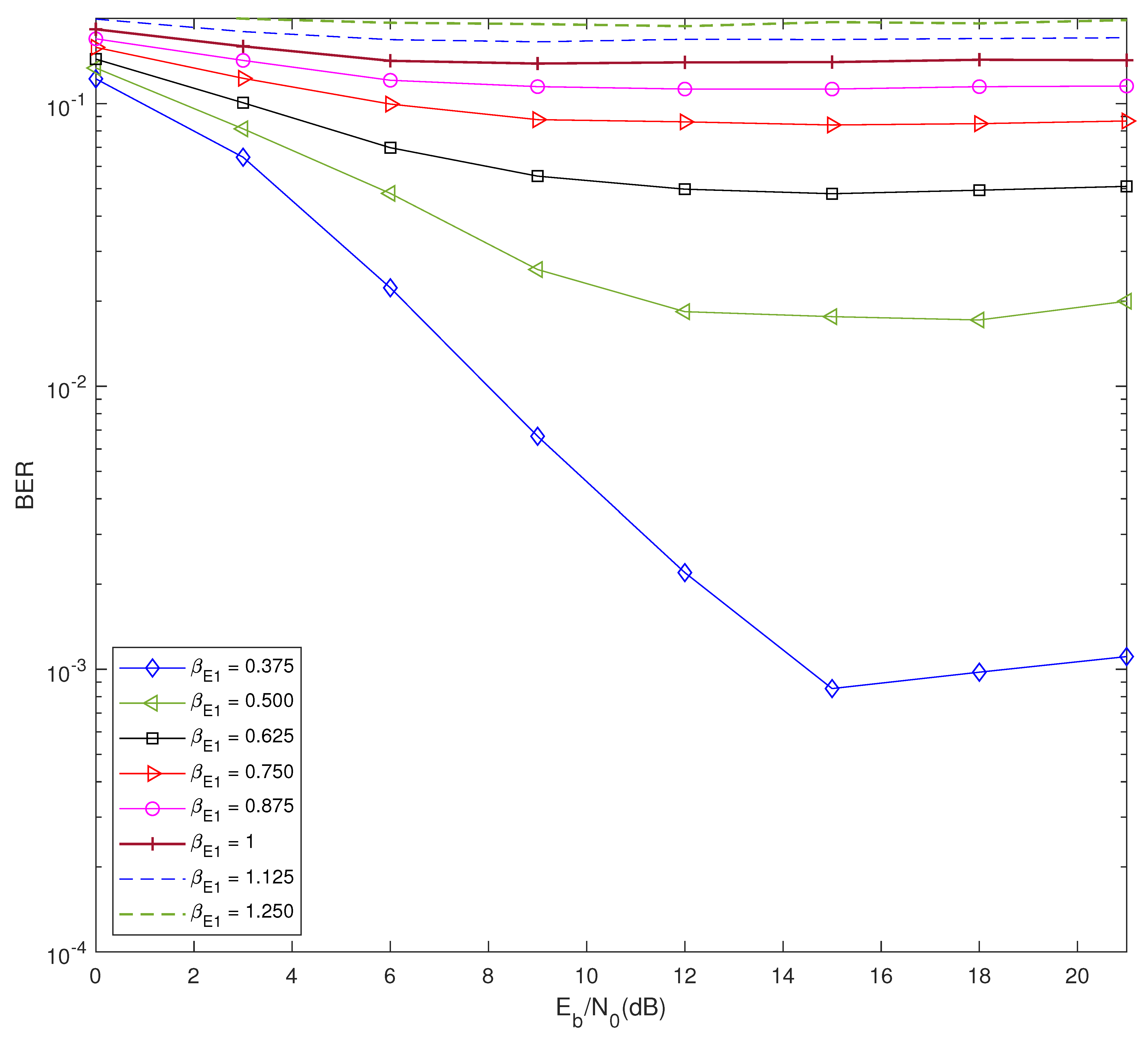
Figure 2 demonstrates the BER performance of E1 with . In this simulation, E1 does not receive the jamming signal estimate feedback from E2. The BER performance degrades with the increase in value and also by increasing . In Figure 3, the comparison of BER results demonstrates that E1 can improve BER by increasing when , as compared to that of when .
Table 1 is an tabulation of Figure 2 values and, with this, and are calculated based on the path loss factor, distance between signal transmitting node and receiving node, and and .
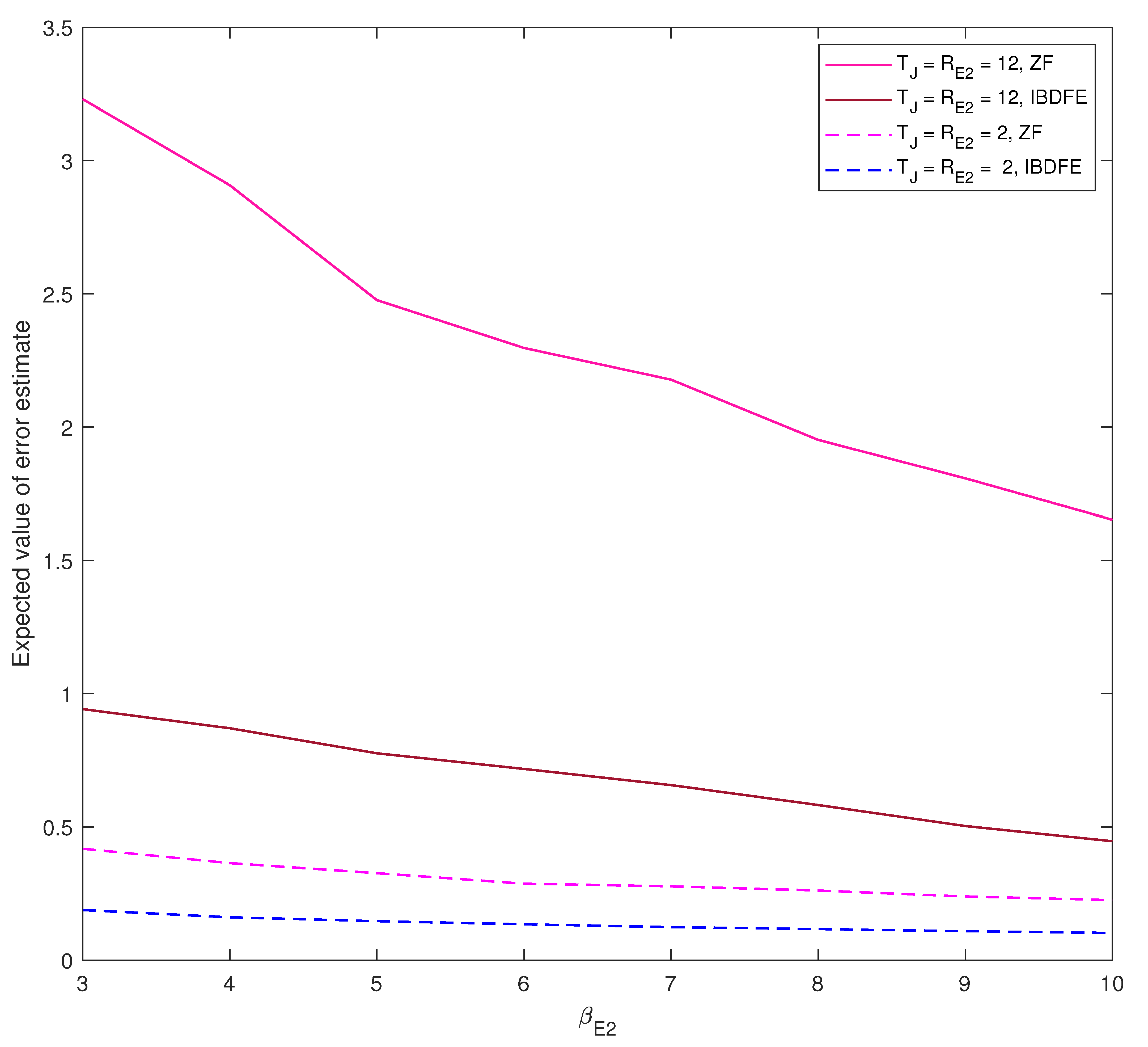
In the following simulations, dBm is considered as an operating SNR and, for this operating SNR, we determine the optimum that is suitable for legitimate users to degrade the performance of the cooperative eavesdropper. In Figure 4 and Figure 5, for the fixed operating SNR, i.e., 12 dBm, the performance of E2 is measured for values against the expected jamming signal estimate error. Since the jamming signal is random in nature, instead of BER, the expected error for detecting jamming signal is considered for performance measurement.
Figure 4 demonstrates that the expected error of the jamming signal estimate error reduces with the increase in value, but the rate of reduction in error saturates with the increase in . In this simulation, the performance of E2 can be degraded by increasing at the J. By increasing the , we can reduce the SNR of individual jamming signals while keeping the total power of combined jamming signals at constant. In order to use the IBDFE receiver, E2 should satisfy . Thus, in this simulation, we set . The observation of the results of Figure 4, based on the increase in , degrades the performance of E2, even if , which satisfies (15). Therefore, by increasing , J can degrade E2 performance. Figure 5 demonstrates the drastic performance improvement of E2 with the application of the IBDFE decoder over the ZF decoder with the increase in . The increase in , degrades SNR, as in (15), but this SNR degradation impact is reduced with the increase in feedback diversity order in IBDFE, due to . Therefore, with the increase in , the performance degradation due to SNR degradation is lower in IBDFE, as compared to ZF.
Figure 6 demonstrates the BER results of the information signal after reducing the interference of the jamming signal by using the jamming signal estimate from E2. The expected jamming signal estimate error is tabulated in Table 2. To degrade the performance of E1 and E2, J increases , this is observed from the BER results. When is increased, the performance of E2 degrades and the error in the jamming signal estimate feedback increases, as in Table 2. The BER results show that, by increasing the value above 1 and by increasing , J can degrade E1 performance. Even though increase in degrades the BER results of E1, it is optimal to set instead of increasing above 1. This is observed with the increase in . Therefore, from the simulated results, for operating SNR at 12 dBm, it is optimal to set .
Figure 7 demonstrates the advantage of using IBDFE over the ZF decoder at E1. Even though IBDFE performs better than ZF, the increase in can degrade the performance of IBDFE and the performance gap between IBDFE and ZF decreases with the increase in . Therefore, with the help of and , J can degrade cooperative eavesdropper performance with the least possible energy expenditure. The comparison of results of the ZF and IBDFE decoder at shows that the performance of IBDFE is better than that of ZF. The comparison of IDBFE performance in terms of SNR shows that there is a slight performance degradation at SNR—18 dBm over SNR 15 dBm—and this result is contrary to the expected result. The reason for this unexpected degradation in BER is due to the incorrect noise power input in the feed forward in (12), and for the single antenna case, refer to [6]. The amount of energy saved at J, when over , is calculated as .
4. Conclusions
In this research work, we study a cooperative eavesdropper model in a wire-tap channel and derive the SINR of the jamming signal and information signal for the cooperative eavesdroppers network. We specifically consider that the eavesdropper has the CSI of the nearest node with negligible channel estimate error in order to study the optimum (i.e., power ratio between the jamming signal and information signal). The simulated results of the expected jamming signal estimate error at the nearest eavesdropper (i.e., E2) to the jammer shows that, by increasing the total of number of antennas at the jammer, the jammer can degrade the performance of E2, even if E2 has an equal number of receiving antennas. Therefore, jamming the signal SNR degradation at E2 can degrade the performance of the MIMO IBDFE receiver.
The BER results of the information signal at the nearest eavesdropper (i.e., E1) to the transmitter show that the BER of E1 can be degraded by optimizing the value at E1 to 1. The optimization of leads to energy efficient and secure communication, since at E1 is better for the legitimate network than for using a greater than 1. Therefore, we conclude that, under a severely restricted environment, a legitimate network can improve the secrecy rate and can achieve better energy efficiency by increasing the number of antenna at a jammer and by optimizing .
Author Contributions
Conceptualization, A.R. and R.D.; investigation, A.R., M.B. and R.D.; software, A.R.; supervision, R.D. and D.N.K.J.; validation, D.N.K.J. and R.D.; visualization, A.R.; writing—original draft, A.R., M.B., D.N.K.J. and R.D.; writing—review and editing, A.R. and R.D. All authors have read and agreed to the published version of the manuscript.
Funding
This work is supported by FCT/MCTES Copelabs (UIDB/04111/2020) and Instituto de Telecomunicações (UIDB/EEA/50008/2020). The research work is developed in part with Universidade Lusòfona/ILIND funding and supported, in part, by the Russian Foundation for Basic Research (RFBR) grant No 19-37-50083\19. Also, in part, by the framework of Competitiveness Enhancement Program of the National Research Tomsk Polytechnic University, Russia.
Institutional Review Board Statement
Not applicable.
Informed Consent Statement
Not applicable.
Conflicts of Interest
The authors declare no conflict of interest.
References
- Jayakody, D.N.K.; Thompson, J.; Chatzinotas, S.; Durrani, S. Wireless Information and Power Transfer: A New Green Communications Paradigm; Springer: New York, NY, USA, 2017. [Google Scholar]
- Perera, T.D.P.; Jayakody, D.N.K.; Sharma, S.K.; Chatzinotas, S.; Li, J. Simultaneous wireless information and power transfer (swipt): Recent advances and future challenges. IEEE Commun. Surv. Tutor. 2018, 20, 264–302. [Google Scholar] [CrossRef] [Green Version]
- Khan, R.; Kumar, P.; Jayakody, D.N.K.; Liyanage, M.; Li, J. A Survey on Security and Privacy of 5G Technologies: Potential Solutions, Recent Advancements and Future Directions. IEEE Commun. Surv. Tutor. 2019, 22, 196–248. [Google Scholar] [CrossRef] [Green Version]
- Rajaram, A.; Khan, R.; Tharranetharan, S.; Jayakody, D.; Dinis, R.; Panic, S. Novel SWIPT Schemes for 5G Wireless Networks. Sensors 2019, 19, 1169. [Google Scholar] [CrossRef] [PubMed] [Green Version]
- Rajaram, A.; Jayakody, D.N.K.; Dinis, R.; Kumar, N. Receiver Design to Employ Simultaneous Wireless Information and Power Transmission with Joint CFO and Channel Estimation. IEEE Access 2019, 7, 9678–9687. [Google Scholar] [CrossRef]
- Rajaram, A.; Dinis, R.; Jayakody, D.N.K.; Beko, M. Secure Information Transmission with Self Jamming SWIPT. Electronics 2020, 9, 587. [Google Scholar] [CrossRef] [Green Version]
- Tang, X.; Cai, Y.; Yang, W.; Yang, W.; Chen, D.; Hu, J. Secure transmission of cooperative zero-forcing jamming for two-user SWIPT sensor networks. Sensors 2018, 18, 331. [Google Scholar] [CrossRef] [PubMed] [Green Version]
- Wyner, A.D. The wire-tap channel. Tech. Rep. 1975. [Google Scholar] [CrossRef]
- Leung-Yan-Cheong, S.; Hellman, M. The Gaussian wire-tap channel. IEEE Trans. Inf. Theory 1978, 24, 451–456. [Google Scholar] [CrossRef]
- Oggier, F.; Hassibi, B. The Secrecy Capacity of the MIMO Wiretap Channel. IEEE Trans. Inf. Theory 2011, 57, 4961–4972. [Google Scholar] [CrossRef] [Green Version]
- Goel, S.; Negi, R. Guaranteeing Secrecy using Artificial Noise. IEEE Trans. Wirel. Commun. 2008, 7, 2180–2189. [Google Scholar] [CrossRef]
- Cumanan, K. Physical Layer Security Jamming: Theoretical Limits and Practical Designs in Wireless Networks. IEEE Access 2017, 5, 3603–3611. [Google Scholar] [CrossRef] [Green Version]
- Anjos, G.; Castanheira, D.; Silva, A.; Gameiro, A.; Gomes, M.; Vilela, J.P. Exploiting the Reciprocal Channel for Discrete Jamming to Secure Wireless Communications Against Multiple-Antenna Eavesdropper. IEEE Access 2018, 6, 1–10. [Google Scholar] [CrossRef]
- Anjos, G.; Castanheira, D.; Silva, A.; Gameiro, A. Exploiting Reciprocal Channel Estimations for Jamming to Secure Wireless Communications. In Proceedings of the International Wireless Days Conference, Porto, Portugal, 29–31 March 2017. [Google Scholar]
- Liao, W.; Chang, T.; Ma, W.; Chi, C. QoS-Based Transmit Beamforming in the Presence of Eavesdroppers: An Optimized Artificial-Noise-Aided Approach. IEEE Trans. Signal Process. 2011, 59, 1202–1216. [Google Scholar] [CrossRef]
- Ji, B.; Han, Y.; Li, P.; Mumtaz, S.; Song, K.; Li, C.; Wang, D.; Wen, H. Research on Secure Transmission Performance of Electric Vehicles Under Nakagami-m Channel. IEEE Trans. Intell. Transp. Syst. 2020, 1–11. [Google Scholar] [CrossRef]
- Yeoh, P.L.; Yang, N.; Kim, K.J. Secrecy Outage Probability of Selective Relaying Wiretap Channels with Collaborative Eavesdropping. In Proceedings of the 2015 IEEE Global Communications Conference (GLOBECOM), San Diego, CA, USA, 6–10 December 2015; pp. 1–6. [Google Scholar] [CrossRef]
- Yang, J.; Kim, I.; Kim, D.I. Optimal Cooperative Jamming for Multiuser Broadcast Channel with Multiple Eavesdroppers. IEEE Trans. Wirel. Commun. 2013, 12, 2840–2852. [Google Scholar] [CrossRef]
- Benvenuto, N.; Tomasin, S. Block iterative DFE for single carrier modulation. Electron. Lett. 2002, 38, 1144–1145. [Google Scholar] [CrossRef] [Green Version]
- Silva, A.; Assunção, J.; Dinis, R.; Gameiro, A. Performance Evaluation of IBDFE based Strategies for SC-FDMA Systems. EURASIP J. Wirel. Commun. Netw. 2013, 2013, 1–10. [Google Scholar] [CrossRef] [Green Version]
- Castanheira, D.; Silva, A.; Dinis, R.; Gameiro, A. Efficient Transmitter and Receiver Designs for SC-FDMA Based Heterogeneous Networks. IEEE Trans. Commun. 2015, 63, 2500–2510. [Google Scholar] [CrossRef]
- Silva, A.; Teodoro, S.; Dinis, R.; Gameiro, A. Iterative Frequency-Domain Detection for IA-Precoded MC-CDMA Systems. IEEE Trans. Commun. 2014, 62, 1240–1248. [Google Scholar] [CrossRef] [Green Version]
- Borges, D.; Montezuma, P.; Ferreira, A.; Dinis, R. Two Low Complexity MRC and EGC Based Receivers for SC-FDE Modulations with Massive MIMO Schemes. J. Signal Process. Syst. 2018, 90, 1357–1367. [Google Scholar] [CrossRef]
Figure 1.
Cooperative eavesdroppers in the system model. In this model, the jamming signal does not interfere with legitimate users.
Figure 1.
Cooperative eavesdroppers in the system model. In this model, the jamming signal does not interfere with legitimate users.

Figure 2.
The BER results of E1 without the feedback of jamming signal estimate, where , .

Figure 3.
The BER results of E1 without the feedback of jamming signal estimate, where , .

Figure 4.
The expected jamming signal estimate error at E2 with the feedback of information signal estimate, where .
Figure 4.
The expected jamming signal estimate error at E2 with the feedback of information signal estimate, where .

Figure 5.
The performance of IBDFE versus ZF at E2, where the feedback of information signal estimate is included to reduce interference.
Figure 5.
The performance of IBDFE versus ZF at E2, where the feedback of information signal estimate is included to reduce interference.

Figure 6.
The BER results of E1 with the feedback of jamming signal estimate, where .

Figure 7.
The performance of IBDFE versus ZF at E1, where the feedback of jamming signal estimate is included to reduce interference.
Figure 7.
The performance of IBDFE versus ZF at E1, where the feedback of jamming signal estimate is included to reduce interference.


Table 1.
The received signal power of and at E1 and E2, and for the given transmit power, and (is considered at 12 dBm SNR) from Figure 2.
Table 1.
The received signal power of and at E1 and E2, and for the given transmit power, and (is considered at 12 dBm SNR) from Figure 2.
| 1 | 100 | 150 | 4 | 1 | 3 | 3 | 0.0022 | ||
| 2 | 100 | 200 | 4 | 1 | 4 | 4 | 0.0184 | ||
| 3 | 100 | 250 | 4 | 1 | 5 | 5 | 0.048 | ||
| 4 | 100 | 300 | 4 | 1 | 6 | 6 | 0.086 | ||
| 5 | 100 | 350 | 4 | 1 | 7 | 7 | 0.1125 | ||
| 6 | 100 | 400 | 4 | 1 | 8 | 8 | 0.1399 | ||
| 7 | 100 | 450 | 4 | 1 | 9 | 9 | 0.1685 | ||
| 8 | 100 | 500 | 4 | 1 | 10 | 10 | 0.1878 |
Table 2.
Tabulation of from Figure 4.
Table 2.
Tabulation of from Figure 4.
| at | at | at | ||
|---|---|---|---|---|
| 1 | 6 | |||
| 2 | 8 | |||
| 3 | 10 | |||
| 4 | 11 |
Publisher’s Note: MDPI stays neutral with regard to jurisdictional claims in published maps and institutional affiliations. |
© 2021 by the authors. Licensee MDPI, Basel, Switzerland. This article is an open access article distributed under the terms and conditions of the Creative Commons Attribution (CC BY) license (http://creativecommons.org/licenses/by/4.0/).
Share and Cite
MDPI and ACS Style
Rajaram, A.; Jayakody, D.N.K.; Dinis, R.; Beko, M. Energy Efficient Secure Communication Model against Cooperative Eavesdropper. Appl. Sci. 2021, 11, 1563. https://0-doi-org.brum.beds.ac.uk/10.3390/app11041563
AMA Style
Rajaram A, Jayakody DNK, Dinis R, Beko M. Energy Efficient Secure Communication Model against Cooperative Eavesdropper. Applied Sciences. 2021; 11(4):1563. https://0-doi-org.brum.beds.ac.uk/10.3390/app11041563
Chicago/Turabian StyleRajaram, Akashkumar, Dushnatha Nalin K. Jayakody, Rui Dinis, and Marko Beko. 2021. "Energy Efficient Secure Communication Model against Cooperative Eavesdropper" Applied Sciences 11, no. 4: 1563. https://0-doi-org.brum.beds.ac.uk/10.3390/app11041563
Note that from the first issue of 2016, this journal uses article numbers instead of page numbers. See further details here.