
Simulation Design of Incremental Leg Tapered Birdcage Coil for Head Imaging at 4.7T MRI


1
Department of Health Sciences and Technology, GAIHST, Gachon University, Incheon 21999, Korea
2
Department of Biomedical Engineering, Medical Campus, Gachon University, Incheon 21936, Korea
*
Authors to whom correspondence should be addressed.
Appl. Sci. 2021, 11(5), 2064; https://0-doi-org.brum.beds.ac.uk/10.3390/app11052064
Submission received: 8 January 2021
/
Revised: 20 February 2021
/
Accepted: 23 February 2021
/
Published: 26 February 2021
(This article belongs to the Section Applied Biosciences and Bioengineering)
Abstract
:This study analyzed asymmetrical designs of birdcage (BC) coils, for which the conventional shape of the BC is modified in order to improve field intensity and uniformity in the brain region for magnetic resonance imaging (MRI) at 4.7T. Typically the BC coil has insufficient field uniformity when operating at higher frequencies such as 200 MHz, corresponding to the Larmor frequency at 4.7T, due to the interaction between the electrical properties of body tissue and the propagated magnetic field wavelength. We propose a new design of BC coil, which consists of different ring diameters and leg width. The performance of proposed designs was compared to that of a head-size BC coil. Using finite-difference time-domain simulations to obtain the || fields for a human model, we demonstrate that the proposed designs can achieve better field intensity and uniformity compared with other BC coil designs.
1. Introduction
Advances in medicine and technology have made it possible to produce brain images using magnetic resonance imaging (MRI). Moreover, improvements in MRI technology have led to image quality enhancements. A great deal of research has been invested in increasing the magnetic field strength of MRI systems with the objective of producing images with a higher signal-to-noise ratio (SNR) because increasing the magnetic field strength polarizes a larger number of protons, thereby producing stronger signals.
Increasing the frequencies used in MRI systems, which results from the development of stronger magnets, requires the design of a radiofrequency (RF) coil that is capable of producing a field with high intensity and uniformity [1]. However, at higher frequencies, the || field uniformity is affected by wavelength shortening [2], and the performance of coils with high uniformity in smaller MRI systems, birdcage (BC) coils, for example, is reduced at higher frequencies [3].
BC coils [4,5,6] are typically used in MRI experiments because they can generate a uniform magnetic field across their volume [7]. A BC coil consists of two rings with equal diameters that, although separated by a certain distance, are connected to each other by the coil legs. A BC coil with N legs has different resonant modes [8,9]. In those modes, operating frequency can be predicted among other modes, such as ring modes [10], and is known to have more uniform || field distribution when the number of legs increases [11]. However, the BC coil underperforms when used in higher frequencies, because the magnetic field interacts with brain tissues that have different electromagnetic properties (conductivity and permittivity) [12]. The field uniformity is affected by shortened RF wavelengths and the resulting wavelength is significantly smaller than the imaging object, which is contrary to the case of using lower fields, leading significant field uniformity drop in 4.7T or higher [13]. Another field uniformity consideration is the electric (E) field, which can lead to local power absorption peaks in the tissues or in the measurement of the specific absorption rate (SAR), which is linked to localized tissue heating [14]. Generally, a uniform field yields a lower SAR values [15,16,17]. BC coils also follow these rules, with a higher frequency of the main magnet leading to reduced homogeneity and higher SAR for the produced field [18].
This study proposes a BC design with a varying geometry to achieve better field intensity and uniformity compared with previously proposed asymmetric BC coils [19,20,21]. In the study by [22], the proposed BC coil utilizes an approximately elliptical shape to accommodate the upper body of a human subject, with the study concluding that a highly uniform field was achieved. Furthermore, in the study by [23], an asymmetric BC coil for small animals is proposed, for which half of the BC coil is offset by a certain distance. This modification to the conventional coil design provided an improved field distribution. The patent [24] describes a tampered birdcage coil for improved homogeneity, in which one of the BC rings is smaller than the other. In this study, a BC coil design that is nonsymmetrical with regard to the ring diameters is proposed to focus the magnetic field on the brain.
2. Materials and Methods
Previous studies have demonstrated that large BC coils produce more uniform magnetic fields under the loading condition, but the field intensity is lower. In contrast, smaller BC coils produce stronger field intensity at the expense of lower field uniformity and produce the central field effect [25]. To optimize the BC coil geometry and produce a uniform field with a large BC coil that has the intensity of a small BC coil, we propose the design of a BC coil with different ring diameters in which the rings are connected to each other. We compared our design with a head BC that is frequently used as conventional coil. The head BC had a length of 280 mm and diameter of 280 mm, as shown in Figure 1a.
To gain a more complete understanding of how the magnetic field inside the brain and other human tissues can be improved, we used a dedicated simulation software [26] (Sim4Life, Zurich, Switzerland) to solve the corresponding equations and obtain the magnetic field.
The proposed coil design has a shape that resembles a yurt tent and is therefore referred to as the “yurt BC coil”. This coil consists of a comparatively small ring with a diameter of 100 mm located at the top and a larger ring with a diameter of 600 mm located at the base. This coil consists of 16 legs; however, here, the legs between the rings are not connected directly but are instead connected in three sections. The first section, with a leg length of 372 mm and width of 5 mm, is connected to an imaginary diameter of 400 mm that is 340 mm away from the top ring. The second section has a length of 168 mm and width of 5 mm, which is connected from the previous section to a 600 mm diameter imaginary circle located at a length of 135 mm along the z-axis. Finally, the last section is connected to the 600 mm diameter ring at the base in a 324.5 mm long straight line with 5 mm width. The yurt BC coil design is illustrated in Figure 1b. The capacitor placement in the smaller ring of the yurt coil is shown in Figure 1c. The main concept in this design is that the focus of the magnetic field on the periphery of the small ring increases as the coil legs approach each other. The legs of the yurt BC coil are closer to the human head, which helps increase the field intensity compared with the head BC coil. The concept underlying this coil design is that the magnetic field focus can be changed from being off-center, and to maintain a strong field even when the distance between the legs and the subject is increased. The coil length is extended such that the field is focused on the brain area. However, extending the coil length also requires that the ring radius increases such that it is at least shoulder-wide, as shown in Figure 1.
We conducted RF simulations using the finite-difference time-domain (FDTD) software Sim4Life, thereby acquiring || field maps. The entire structure was considered to be a perfect electric conductor. A human model (DUKE) served as the basis for our simulations [27], with the basic position altered such that the arms were close to the body, consistent with standard MRI protocol. This human model consisted of over 100 tissues provided by the simulation software, and the electrical properties of each tissues were set to corresponding values at 200 MHz.
The coils were excited by a Gaussian voltage current signal with a central frequency of 200 MHz and a bandwidth of 400 MHz. Notably, the coils were excited by two voltage sources and tuned with ring capacitors. A phase shift with a difference of 90° in total was applied between the voltage sources. For each coil type, the input power was normalized to 1 W. Figure 2 shows the S-parameters for each of the coils while loaded with the human model phantom, and the tuning of the head BC coils (Figure 2a) was done with ring capacitors of 4.1 pF. The Yurt coil in Figure 2b was tuned with capacitors in the small ring of 3.6 pF and in the large ring of 6 pF.
Considering that the field intensity is different for each coil and to visualize the field uniformity satisfactorily, for the case of the axial head view, we compared the field maps by scaling the || field with the max SAR value of the entire head model. The magnetic fields were analyzed by calculating the mean magnetic field intensity and relative uniformity (RU), which is computed by taking the percentage of values within a range of 10% of variation from the mean. The total number of pixels consisted of pixels with value larger than zero.
In Equation (1), the value of pixels represents the number of pixels in the field map that follow the criteria inside the brackets. The criteria are that each pixel is deviation with the mean value not being 10%.
The average SAR10g maps were obtained using the FDTD software and included the entire field of view inside each coil.
3. Results
RF FDTD simulations were performed to test the design of the proposed volume coil on the basis of a nonsymmetrical shape. We acquired || field maps from the yurt coil and compared its performance with the head birdcage coil. We used the human model DUKE from the virtual family provided by the EM simulation software.
The || field maps were computed with an input power normalized to 1 W for each BC coil. The field maps were normalized with the square root of the maximum SAR10g of the whole head model, as given by
This normalization makes it easier to compare the performance of each type coil. Using this visualization, we were able to analyze which coils can produce uniform fields.
Simulations with the human model were conducted for all the coils, and the || fields were extracted in the xy-plane slices along the head model (z-axis). Figure 3a,b shows the performances of the head and yurt BC coils, respectively. Each column represents a different slice of the brain region.
Table 1 shows the mean || value and the relative uniformity (RU) for each coil at the whole head model. The yurt coil produces a higher field intensity than the head BC. The comparison with the RU shows that the yurt BC coil has better field uniformity compared with the reference head BC coil. Therefore, the yurt coil demonstrated the optimal performance. The values measured for the yurt BC coil indicated better performance compared with the head BC coil.
Additionally, Figure 4 shows the || field in the zy-plane for each coil. The first aspect of the figure to note is the field intensity produced by each coil. The central field effect can be observed clearly in the head BC coil. Notably, however, the field from the yurt BC coil increases in the cortex area, which has a higher field intensity compared with the head BC coil, as can be seen by comparing Figure 4a,b.
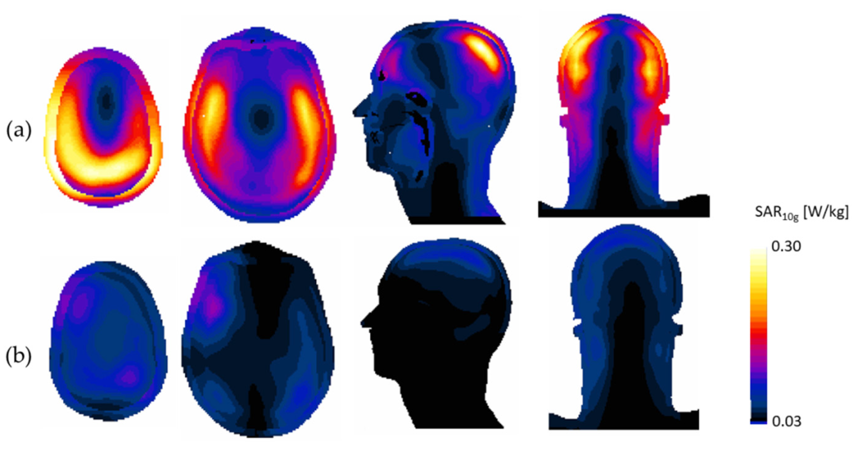
Next, SAR10g maps were obtained from each coil, as shown in Figure 5. The axial slices in Figure 5 correspond to the maximum SAR from each of the coil. The SAR value of the head coil was higher than yurt coil. The peak SAR values in the head model volume were 0.31 and 0.09 W/Kg for the head BC and yurt coil, respectively. Moreover, the mean SAR values for the head BC and yurt coil were 0.068 and 0.02 W/kg, respectively. The occurrence of the peak SAR value in this area was unsurprising because the coil geometry is narrower at the top ring of the yurt BC coil relative to the other designs.
4. Discussion
In this study, we present a new yurt-shaped volume coil design. We performed RF FDTD simulations with a human model. We compared the performance of the yurt coil to a reference BC coil for head. || fields were extracted from the human model, specifically for the brain region, and the SAR values were also computed for the brain area. The proposed yurt BC coil was designed with an asymmetrical geometry to overcome the homogeneity drop in the focus of the field that arises at shorter wavelengths, which can be considered a side effect of the technological developments intended to improve the intensity of the main magnet.
The yurt BC coil demonstrated better field uniformity when compared to the other BC coil designs, showing a good relationship between field intensity and uniformity.
Although the yurt BC coil enables the enhancement of the || field in the head region, resulting in high uniformity and field intensity in the brain region, drawbacks of the proposed design are its complicated structure and comparably large size. The size of the small ring was chosen to provide uniform field in the head area, and further changes of the small ring will require modifying the angle of the legs. The angle of the legs should be taking into account the distance to the head model. The yurt BC coil showed a lower SAR level to the ordinary head BC coil. We hypothesize that the peak SAR value of the yurt BC coil can be artificially located by modifying the position of the smaller ring. We hope that the proposed yurt BC coil design can show that the modification of the symmetrical BC can contribute to improvement of || field and the reduction of SAR and also be applied to practical experiments in future studies.
Author Contributions
Formal analysis, D.H.; methodology, H.S.; supervision, D.H.; supervision, K.-N.K.; funding acquisition, K.-N.K. All authors have read and agreed to the published version of the manuscript.
Funding
This research was funded by the National Research Foundation of Korea under grant NRF-2017M3C7A104722821 and by the Gachon University Gil Medical Center (grant number: FRD 2020-15).
Institutional Review Board Statement
Not applicable.
Informed Consent Statement
Not applicable.
Data Availability Statement
No new data were created or analyzed in this study. Data sharing is not applicable to this article.
Acknowledgments
In this section, you can acknowledge any support given which is not covered by the author contribution or funding sections. This may include administrative and technical support, or donations in kind (e.g., materials used for experiments).
Conflicts of Interest
The authors declare no conflict of interest.
References
- Ipek, Ö. Radio-frequency coils for ultra-high field magnetic resonance. Anal. Biochem. 2017, 529, 10–16. [Google Scholar] [CrossRef]
- Sohn, S.M.; DelaBarre, L.; Gopinath, A.; Vaughan, J.T. RF head coil design with improved RF magnetic near-fields uniformity for magnetic resonance imaging (MRI) systems. IEEE Trans. Microw. Theory. Tech. 2014, 62, 1784–1789. [Google Scholar] [CrossRef] [PubMed] [Green Version]
- Vaughan, J.T.; Adriany, G.; Snyder, C.J.; Tian, J.; Thiel, T.; Bolinger, L.; Liu, H.; DelaBarre, L.; Ugurbil, K. Efficient high-frequency body coil for high-field MRI. Magn. Reason. Med. 2004, 52, 851–859. [Google Scholar] [CrossRef] [PubMed]
- Boissoles, P.; Caloz, G. Magnetic Field Properties in a Birdcage Coil. 2006. Available online: https://hal.archives-ouvertes.fr/hal-00020757 (accessed on 26 February 2021).
- Tomanek, B.; Volotovskyy, V.; Gruwel, M.L.; Mckenzie, E.; King, S.B. Double-frequency birdcage volume coils for 4.7 T and 7T. Concepts Magn. Reason. Part B Magn. Reason. Eng. 2005, 26, 16–22. [Google Scholar] [CrossRef]
- Zanche, N.D. Birdcage Volume Coil Design; eMagRes: Hoboken, NJ, USA, 2007. [Google Scholar]
- Hayes, C.E.; Edelstein, W.A.; Schenck, J.F.; Mueller, O.M.; Eash, M. An efficient, highly homogeneous radiofrequency coil for whole-body NMR imaging at 1.5 T. J. Magn. Reson. 1985, 63, 622–628. [Google Scholar] [CrossRef]
- Giovannetti, G.; Landini, L.; Santarelli, M.F.; Positano, V. A fast and accurate simulator for the design of birdcage coils in MRI. MAGMA 2002, 15, 36–44. [Google Scholar] [CrossRef] [Green Version]
- Lin, F.H.; Kwong, K.K.; Huang, I.J.; Belliveau, J.W.; Wald, L.L. Degenerate mode birdcage volume coil for sensitivity-encoded imaging. Magn. Reason. Med. 2003, 50, 1107–1111. [Google Scholar] [CrossRef] [PubMed]
- Leifer, M.C. Resonant modes of the birdcage coil. J. Magn. Reason. 1997, 124, 51–60. [Google Scholar] [CrossRef]
- Seo, J.-H.; Han, S.-D.; Kim, K.-N. Investigation of the B1 field distribution and RF power deposition in a birdcage coil as functions of the number of coil legs at 4.7 T, 7.0 T, and 11.7 T. J. Korean Phys. Soc. 2015, 66, 1822–1826. [Google Scholar] [CrossRef]
- Gabriel, S.; Lau, R.W.; Gabriel, C. The dielectric properties of biological tissues: II. Measurements in the frequency range 10 Hz to 20 GHz. Phys. Med. Biol. 1996, 41, 2251. [Google Scholar] [CrossRef] [PubMed] [Green Version]
- Webb, A.G.; Collins, C.M. Parallel transmit and receive technology in high-field magnetic resonance neuroimaging. Int. J. Imaging Syst. Technol. 2010, 20, 2–13. [Google Scholar] [CrossRef]
- Wang, Z.; Lin, J.C.; Mao, W.; Liu, W.; Smith, M.B.; Collins, C.M. SAR and temperature: Simulations and comparison to regulatory limits for MRI. J. Magn. Reason. Imaging 2007, 26, 437–441. [Google Scholar] [CrossRef] [Green Version]
- Yeo, D.T.; Wang, Z.; Loew, W.; Vogel, M.W.; Hancu, I. Local specific absorption rate in high-pass birdcage and transverse electromagnetic body coils for multiple human body models in clinical landmark positions at 3T. J. Magn. Reason. Imaging 2011, 33, 1209–1217. [Google Scholar] [CrossRef] [PubMed] [Green Version]
- Zeng, Q.; Guo, R.; Zheng, J.; Chen, J. Impacts of RF shimming on local SAR caused by MRI 3T birdcage coil near femoral plate implants. In Proceedings of the 2017 IEEE International Symposium on Antennas and Propagation & USNC/URSI National Radio Science Meeting, San Diego, CA, USA, 9–14 July 2017; pp. 1005–1006. [Google Scholar]
- Wang, C.; Shen, G.X. B1 field, SAR, and SNR comparisons for birdcage, TEM, and microstrip coils at 7T. J. Magn. Reason. Imaging 2006, 24, 439–443. [Google Scholar] [CrossRef] [PubMed]
- Collins, C.M.; Li, S.; Smith, M.B. SAR and B1 field distributions in a heterogeneous human head model within a birdcage coil. Magn. Reason. Med. 1998, 40, 847–856. [Google Scholar] [CrossRef]
- Loew, W.M.; Dumoulin, C.L. Cincinnati Children s Hospital Medical Center. Asymmetric Birdcage Coil for a Magnetic Resonance Imaging (MRI). U.S. Patent Application 16/437,234, 22 March 2019. [Google Scholar]
- Wetterling, F.; Corteville, D.M.; Kalayciyan, R.; Rennings, A.; Konstandin, S.; Nagel, A.M.; Stark, H.; Schad, L.R. Whole body sodium MRI at 3T using an asymmetric birdcage resonator and short echo time sequence: First images of a male volunteer. Phys. Med. Biol. 2012, 57, 4555. [Google Scholar] [CrossRef] [PubMed] [Green Version]
- Dregely, I.; Ruset, I.C.; Wiggins, G.; Mareyam, A.; Mugler, J.P., III; Altes, T.A.; Meyer, C.; Ruppert, K.; Wald, L.L.; Hersman, F.W. 32-channel phased-array receive with asymmetric birdcage transmit coil for hyperpolarized xenon-129 lung imaging. Magn. Reason. Med. 2013, 70, 576–583. [Google Scholar] [CrossRef] [Green Version]
- De Zanche, N.; Chhina, N.; Teh, K.; Randell, C.; Pruessmann, K.P.; Wild, J.M. Asymmetric quadrature split birdcage coil for hyperpolarized 3He lung MRI at 1.5 T. Magn. Reason. Med. 2008, 60, 431–438. [Google Scholar] [CrossRef] [PubMed]
- Kim, K.N.; Han, S.D.; Seo, J.H.; Heo, P.; Yoo, D.; Im, G.H.; Lee, J.H. An Asymmetric Birdcage Coil for Small-animal MR Imaging at 7T. Magn. Reson. Med. Sci. 2017, 16, 253–258. [Google Scholar] [CrossRef] [Green Version]
- Reisker, T.J.; Monski, W.J.; Reid, E.D.; Misic, G.J.; Bayer Medical Care Inc. Tapered Birdcage Resonator for Improved Homogeneity in MRI. U.S. Patent 6,344,745, 5 February 2002. [Google Scholar]
- Avdievich, N.I.; Hetherington, H.P.; Kuznetsov, A.M.; Pan, J.W. 7T head volume coils: Improvements for rostral brain imaging. J. Magn. Reason. Imaging 2009, 29, 461–465. [Google Scholar] [CrossRef] [Green Version]
- Sim4Life, ZMT. Available online: https://www.zmt.swiss (accessed on 26 February 2021).
- Christ, A.; Kainz, W.; Hahn, E.G.; Honegger, K.; Zefferer, M.; Neufeld, E.; Rascher, W.; Janka, R.; Bautz, W.; Chen, J.; et al. The Virtual Family—Development of surface-based anatomical models of two adults and two children for dosimetric simulations. Phys. Med. Biol. 2009, 55, N23. [Google Scholar] [CrossRef] [PubMed]
Figure 1.
Birdcage (BC) coil geometries in sagittal (a) head BC coil, (b) yurt BC coil, and (c) capacitor placement in the yurt small ring.
Figure 1.
Birdcage (BC) coil geometries in sagittal (a) head BC coil, (b) yurt BC coil, and (c) capacitor placement in the yurt small ring.

Figure 2.
The S-parameters of the tuned coils while loaded with the human model (a) head BC coil (b) yurt BC coil.
Figure 2.
The S-parameters of the tuned coils while loaded with the human model (a) head BC coil (b) yurt BC coil.

Figure 3.
|| fields at different slices of human head model for (a) head BC coil and the (b) yurt BC coil.
Figure 3.
|| fields at different slices of human head model for (a) head BC coil and the (b) yurt BC coil.

Figure 4.
|| fields in the sagittal view for (a) head BC coil and the (b) yurt BC coil.

Figure 5.
SAR10g maps in the axial, sagittal, and coronal views of a human model for (a) head BC coil and (b) yurt BC coil.
Figure 5.
SAR10g maps in the axial, sagittal, and coronal views of a human model for (a) head BC coil and (b) yurt BC coil.


Table 1.
The summary of the statistics from the normalized B1 field and specific absorption rate (SAR) from each coil in the whole head model.
Table 1.
The summary of the statistics from the normalized B1 field and specific absorption rate (SAR) from each coil in the whole head model.
| Coil Type | SAR10g | ||||
|---|---|---|---|---|---|
| Mean [µT] | RU [%] | Mean [µT√Kg/W] | Max [W/Kg] | Mean [W/Kg] | |
| BC coil | 0.14 | 38.8 | 0.25 | 0.31 | 0.06 |
| Yurt coil | 0.15 | 40.4 | 0.48 | 0.09 | 0.02 |
Publisher’s Note: MDPI stays neutral with regard to jurisdictional claims in published maps and institutional affiliations. |
© 2021 by the authors. Licensee MDPI, Basel, Switzerland. This article is an open access article distributed under the terms and conditions of the Creative Commons Attribution (CC BY) license (http://creativecommons.org/licenses/by/4.0/).
Share and Cite
MDPI and ACS Style
Song, H.; Kim, K.-N.; Hernandez, D. Simulation Design of Incremental Leg Tapered Birdcage Coil for Head Imaging at 4.7T MRI. Appl. Sci. 2021, 11, 2064. https://0-doi-org.brum.beds.ac.uk/10.3390/app11052064
AMA Style
Song H, Kim K-N, Hernandez D. Simulation Design of Incremental Leg Tapered Birdcage Coil for Head Imaging at 4.7T MRI. Applied Sciences. 2021; 11(5):2064. https://0-doi-org.brum.beds.ac.uk/10.3390/app11052064
Chicago/Turabian StyleSong, Hyunwoo, Kyoung-Nam Kim, and Daniel Hernandez. 2021. "Simulation Design of Incremental Leg Tapered Birdcage Coil for Head Imaging at 4.7T MRI" Applied Sciences 11, no. 5: 2064. https://0-doi-org.brum.beds.ac.uk/10.3390/app11052064
Note that from the first issue of 2016, this journal uses article numbers instead of page numbers. See further details here.