
Thrust Measurements on the High Efficient and Reliable Vacuum Arc Thruster (HERVAT)


1
Institute for Plasma Technology and Basics of Electrical Engineering, Bundeswehr University Munich, Werner-Heisenberg-Weg 39, 85579 Neubiberg, Germany
2
CentraleSupélec, Université Paris-Saclay, 3 Rue Joliot-Curie, 91190 Gif-sur-Yvette, France
*
Author to whom correspondence should be addressed.
Appl. Sci. 2021, 11(5), 2274; https://0-doi-org.brum.beds.ac.uk/10.3390/app11052274
Submission received: 26 January 2021
/
Revised: 24 February 2021
/
Accepted: 28 February 2021
/
Published: 4 March 2021
(This article belongs to the Special Issue Plasmas for Space Propulsion)
Abstract
:In this work, thrust measurements of the high efficient and reliable vacuum arc thruster (HERVAT) are performed for different pulse energies. The thruster system includes a thruster head together with a newly developed pulse processing unit (PPU). The complete system (HERVAT + PPU) is able to perform more than 1 × 10⁷ pulses. Moreover, the influence of an integrated active magnetic nozzle is investigated. As a result, the thrust to power ratio, the average thrust level and the impulse bit for each configuration are measured and calculated. For the thrust measurements, a highly sensitive horizontal thrust balance with an active force actuator is used and operated in the thrust compensation mode. The investigated system is able to achieve levels from 5 to 40 μN and thrust to power ratios from 1 to 2 μN/W. The experimental results are compared to the data available in literature.
1. Introduction
The aerospace industry is undergoing the biggest change since its beginning in 1950: new players in the field of launch services, aerospace technology and space hardware design are rushing into the old agency e.g., National Aeronautics and Space Administration (NASA) or European Space Agency (ESA), shaped business, making space technology available to more users worldwide. In contrast to pure military technology or science missions, the commercialisation of the space is the main focus of these new players like for example SpaceX or Amazon. One of the major projects of those companies are swarm based systems. These systems consist of hundreds or thousands of small satellites (e.g., CubeSats) which are linked together, increasing the performance and availability of the whole system. The use cases for those systems are the communication technology (e.g., internet of space), imaging technologies, science missions and many more. Normally, the satellites are brought into space by carrier rockets, which dispense several hundreds of satellites in a short period of time. In order to start their missions, a successful de-tumbling procedure and precise targeting of each satellite is essential. For these tasks, a low power, less than 2 , low volume, low cost, highly reliable and efficient thruster technology is required [1]. Pulsed vacuum arc thrusters can fulfill these requirements and are under investigation since many years [2,3,4,5].
Vacuum arc thrusters are based on the cathodic vacuum arc and use a solid cathode for thrust generation. Their basic working principle can be described in four steps:
- an electrical breakdown between an anode and cathode is created;
- a vacuum arc establishes and creates a highly ionized plasma from the cathode spots;
- the plasma is streaming away from the cathode’s surface;
- the mass flow and velocity of the plasma generates thrust.
Although the principle of the vacuum thruster is simple and has been known since the seventies [6], the reliability in terms of maximum achievable pulse number is still not satisfactory for such commercial missions. While the efficiency of the system is well described [2,7,8], the long-term reliability is still an open question.
The reliability issue results in the physical process of the thrust generation. During each pulse, the cathode material is slightly eroded and partly re-deposited on the thruster, which depends on parameters like the pulse energy, pulse length, cathode material, etc. At some point, this effect leads to an increased gap or a short circuit between the anode and cathode, which results in an ignition failure and makes the thruster inoperable. There are approaches using an extra cathode feeding device to extend the thrusters lifetime but it increases the complexity of the whole system [9]. A high voltage surface discharge ignition with an extra anode has also been investigated but not tested in a real thruster head [10].
To overcome the reliability issues, the Bundeswehr University Munich invented a novel vacuum arc thruster propulsion system to achieve high pulse numbers (high reliable) without an additional feeding system to generate thrust levels comparable to other vacuum arc thrusters with an optimized cathode erosion (high efficient). The so-called “High Efficient and Reliable Vacuum Arc Thruster” (HERVAT) uses a unique design for the thruster head and a novel pulse processing unit (PPU) instead of the usual inductive energy storage (IES) system [11].
The PPU was operated for more than 5 × 10⁷ pulses in different experiments with variant frequencies (0.2 to 30 Hz) and pulse energies (0.2 to 5 J). During the tests no failure or degradation of the PPU was observed. The thruster head, together with the PPU, was operated for more than 10 × 106 pulses with a pulse energy of . The absence of a feeding mechanism lowers the overall mass of the system and increases the reliability due to the fact that no moving parts or additional power control lines are required.
Furthermore, the thruster’s PPU is automatically operated in the “trigger-less” mode [12] or in the high voltage ignition mode and does not require an initial conductive coating like other systems [13].
In this work, the developed HERVAT system is experimentally investigated for the first time in terms of thrust performance, including the thrust to power ratio (TTPR). Moreover, electrical measurement are performed to investigate the energies consumed by the PPU for each discharge pulse as well as the energy dissipated in the arc. Here, experiments with different pulse energies and magnetic nozzle configurations are conducted. The results are discussed and compared to other systems available in the literature.
2. Experimental Setup
2.1. HERVAT Geometry
The HERVAT has a concentric design with an auxiliary anode positioned at the central axis of the thruster and a toroidal main trigger anode (Figure 1). The main trigger anode is responsible for the vacuum breakdown and the main current conduction during the HERVAT operation. The auxiliary anode stabilizes the ignition behaviour and arc evolution in the case of cathode being substantially eroded toward the inside of the thruster. This phenomenon occurs because of an increased anode area available for the discharge. The cathode is manufactured from a titanium tube (99.97%) with an outer diameter of 10 and a wall thickness of 1 . The auxiliary anode is made out of a tungsten rod with a 1 diameter and mounted concentrically inside the cathode. It is fixed by a concentric insulator. The cathode is installed inside an AlO insulator with an outer diameter of 15 and a wall thickness of . The anode geometry ensures a fixed gap of at the front surface between the anode and cathode as illustrated on the right of Figure 1. For the magnetic field generation, an optional coil can be activated. The coil is made out of insulated copper wire with a 1 diameter and has an inductance of 40.2 μH.
The thruster was optimized in terms of mechanical and electrical properties (e.g., auxiliary anode fixing, electrical connection and mounting points). It can achieve more than 1 × 10⁷ pulses without a cathode feeding mechanism, while the ignition voltage is kept below . In Figure 2, cathodes after thruster operations are shown. The cathodes were operated with a pulse energy of around for 1.27 × 10⁷ pulses and 1.01 × 10⁷ pulses, respectively. Here, an unused cathode for reference is also shown.
The thruster head is installed on the thrust balance into a 3D-printed mounting system to ensure electrical insulation with respect to the thrust balance setup and the vacuum chamber. The mounting system’s material is PETG-polymer. It has an operation temperature up to 100 and a very low tendency for water absorption, which is crucial for a good vacuum level. In order to prevent the melting of the printed mounting system during thrust measurements at higher power levels, cool down phases between the measurements are included. For all electrical connections, high voltage insulated wires with cross-section are used.
2.2. Power Supply Unit
The power supply unit is based on a multi level capacitor discharge network with an integrated high voltage trigger system. It switches automatically between the high voltage ignition and the “trigger-less” ignition mode of a vacuum arc. The electrical schematic of the power supply unit is shown in Figure 3.
The circuit uses two capacitors, and , and a triggered SCR to operate in the “trigger-less” ignition mode. For the high voltage ignition, a separate high voltage pulse generator with an output voltage of up to 10 and a pulse energy of around 53 is used. The SCR is triggered synchronously with the applied high voltage pulse.
The charging voltages are = 95 for and = 250 for . The charging resistors and limit the current from and , respectively. The resistors are chosen according to the operation frequency of the thruster. They ensure that the capacitors store the required energy level, when the SCR is triggered. The diode prevents current back-flow from to while blocks the high voltage trigger pulse (up to 10 ). acts as the main discharge capacitor and can be adjusted for different pulse energies while has fixed value of μF. Three different values for , 92.9 μF, 198.2 μF and 436.9 μF are used in order to investigate system behavior at different pulse energies and the resulting pulse lengths. Here, capacitors with a low equivalent series resistance (ESR) and a low equivalent series inductance (ESL), and type electrolyte capacitors for pulsed applications (Panasonic, low ESR) are chosen in order to reduce the parasitic effects during charging and discharging of capacitors.
2.3. Electrical Measurements
The electrical measurements were performed outside the vacuum chamber. The ignition-anode current was measured by a PEARSON coil (model 101, 4 bandwidth), while the aux-anode current was measured with a Hall effect current probe (LeCroy, CP150, 150 bandwidth). The PPU output voltage was measured with a high voltage 1:1000 probe. The PPU board capacitor voltages and , were measured with a 1:10 voltage probe. The measurement points are shown in Figure 3.
2.4. Vacuum Facility
The vacuum facility is evacuated with a two-staged system consisting of a root pump (Pfeiffer DUO LINE 25) and a turbo-molecular pump (Pfeiffer HiPace 700 TMP). The chamber pressure for the experiments was 2.5 × 10⁻⁶ mbar. The vacuum facility was preheated to ensure a high quality vacuum level for the experiments. To avoid unintended pollution, a plasma trap device was used to prevent condensation of the emitted plasma and particle stream from the thruster on the thrust balance or the chamber walls as illustrated in Figure 4.
2.5. Thrust Balance Setup
For the thrust measurements, a torsional thrust balance system from the FOTEK company and based on the system described in [14] has been chosen. This type of thrust measurement system has been used by other researches before and has proven its suitability for a pulsed vacuum arc thruster system [4,8].
The thrust balance setup is composed of a central pivot rotating around a vertical axis and supporting a lever on which two tables are attached at each end, carrying the thruster and an equivalent counterweight (Figure 4, top). Upon the operation of the thruster, a rotational movement of the lever is induced. At the same time, a defined force is applied with an electrostatic actuator on the opposite end of the lever. If both applied forces are equal, the displacement of the lever, measured with an optical interferometric displacement sensor, vanishes. Thus, the force feedback gives the actual thrust value. This operational mode is also known as the compensation mode. The detectable thrust of this balance system ranges from μN up to with a resolution of μN.
2.6. Thrust Measurement Data Acquisition
In order to ensure reproducible thrust measurements, the following measurement procedure was introduced:
- auto zeroing calibration;
- thermal drift measurement; (duration ∼20 )
- activation of the thruster; (settling time ∼50 )
- thrust measurement in the steady state of the balance;
- switching off of the thruster.
The signal evolution during each procedure step is shown in Figure 5. After the automatic calibration in step 1, which eliminates the accumulated thermal drift, the thermal drift of the system at the specific measurement was recorded in step 2 in order to be used in the post processing of the thrust measurement. The response of the thrust balance to the activation of the thruster took approximately 50 , after which the system could be considered in steady state. Hence, the actual thrust measurement was evaluated after post-processing the raw thrust measurement data.
In order to prevent thermal damage of the thruster and the mounting system, a cool down phase was included between repetitions of single thrust measurements. This was necessary due to the rapid anode heat up, which is especially the case at higher pulse rates and energies.
The average thrust per pulse is calculated as the mean value of thrust over the measurement time when the steady-state is achieved. It can be expressed as:
with the total measurement time during the steady state of the thrust balance and the actual measured thrust.
3. Experimental Results
In the following, thrust measurements as well as measured arc energies for different pulse energies with and without magnetic field are presented. All the thrust measurements for each energy configuration were performed at the thruster pulse repetition rate of 10 and averaged over eight consecutive thrust measurements.
3.1. PPU and Arc Energies
The electric measurements of characteristic current and voltage pulses measured throughout the experiments show a highly reliable operation of the PPU (zero failures during all operation modes). Thus, the thruster could be reliably triggered and operated in the main discharge mode for more than 1 × 10⁷ pulses. In Figure 6, typical traces for the thruster operation in the “trigger-less” mode with and without magnetic field produced by the additional electromagnetic nozzle are shown. The measurements were obtained from an average over 100 pulses. Here, the anode currents and the PPU output voltage are illustrated. It is evident that the use of a magnetic nozzle increases the pulse length to 550 μs and the arc voltage to 55 , while the pulse length is only 250 μs with the arc burning at 35 V in the absence of a magnetic field. This effect is well-known and described in [7,8,15]. In the presence of the magnetic field, the maximum arc current drops from 150 to 50 as a result of the additional coil resistance and the effect of the magnetic nozzle on the vacuum arc [16].
In both graphs in Figure 6, it can be observed that the voltage value remains at the level of the arc voltage, after the arc has extinguished. This indicates that the capacitors are not fully discharged. This needs to be considered in the calculation of the effective energy per pulse , which is needed for the determination of TTPR. The energy dissipated from the capacitors into the arc discharge is then given by
The energy input from the high voltage pulse is determined by the high voltage generator circuit. In the current setup it was = 53 . The released energy from the capacitor , depends on the initial charging voltage and the final voltage remaining in that capacitor after the extinguishing of the arc:
Energy losses due to the parasite resistance, inductance and capacitance of the wires from the PPU to the thruster are not taken into account for this work.
The energy dissipated into the arc was obtained by integration of the measured arc currents and voltages over duration of a single pulse using the following relation
with the time for which the current level of the arc falls below 1 A. With these data, the TTPR using the PPU effective energy outputs and the energy dissipated into the arc were calculated and compared. The results are summarised in Table 1. The ratio of the energy stored in the PPU to the energy dissipated in the arc clearly shows the increase of the efficiency with the presence of the magnetic field. The efficiency of 0.9177 was calculated for = μF.
3.2. Thrust Measurements
In Figure 7, the measured average thrust levels for all configurations at the given pulse frequencies are shown. If only the measurement without magnetic field are considered, it can be observed that the increase of leads to an increase of thrust. This is also the case for the group of measurements with an additional magnetic field. Yet, the growth rate is here bigger compared to the case without magnetic field. If all the data are inspected independent of presence of magnetic field, it can be stated that the thrust increases with increasing arc energy with exception of E = J. When taking into account the data presented in Table 1, it is evident that the use of magnetic nozzle increases the thrust significantly with respect to the same value used in the PPU with magnetic nozzle switched off.
Such a behaviour of the thrust-PPU system can be explained when observing the movement of the arc along the auxiliary anode. When no magnetic field is switched on, the arc movement towards the inside of the thruster head can be optically observed. This behaviour can be also confirmed by the increasing auxiliary anode currents at the end of the pulse. In this case, a significant lower ion and particle stream can move out of the thruster head, due to the shielding effect of the cathode. This effect is particularly strong for E = J. The presence of magnetic fields prevents the arc from moving inside the thruster head. Thus, less material is shielded by parts of the thruster head and a higher thrust level can be measured.
3.3. Thrust Performance Measurements
For calculation of TTPR, the energy dissipated into the arc is measured and compared to the achieved thrust level [8,9,15]. Thus, the TTPR was calculated from the above measurements of the thrust and the energy dissipated into the arc and is defined as:
with (respectively, ) the effective input electrical power per pulse (respectively the effective input electrical energy per pulse) and the pulse frequency.
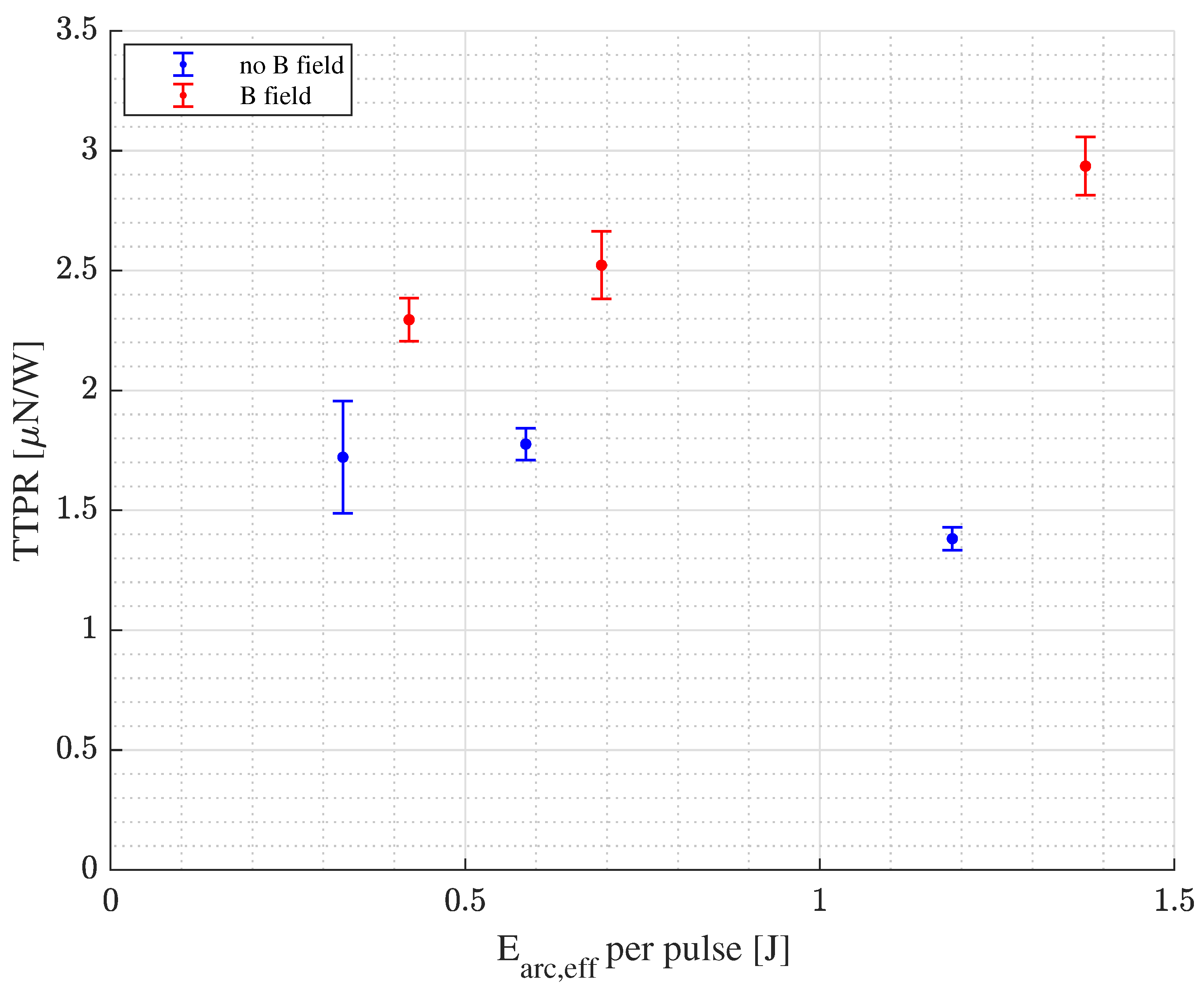
The TTPR calculated for different arc energies is presented in Figure 8. It can be seen, that the TTPR in the presence of magnetic field is higher than without magnetic field. The best TTPR is achieved for E = J. Here, higher capacitance values ( = ) together with the magnetic field extend the pulse lengths. This results in a more stable arc [16]. The rotation of the arc due to magnetic field leads to more homogeneous erosion [17,18].
4. Discussion
Our measurements show a TTPR in the range of 1.4 to 2.9 /−1 and a PPU to arc energy ratios in the range of 0.58 to 0.92. The maximum TTPR of /−1 and also PPU to arc energy ratio of were achieved with = in the presence of magnetic field. Compared to the case without magnetic field, the TTPR as well as the PPU to arc energy ratio were significantly increased. Moreover, no failure of the thruster was detected during the measurements.
The theoretically calculated TTPR for titanium as a cathode material without the use of a magnetic nozzle is about /−1 [2]. Our system lies significantly below this value. One reason for this deviation could be the geometry of our thruster system, which might absorb a significant amount of the generated plasma and neutral particles from the cathode spots and thus reduces the thrust. An optimization of the geometry in addition to an improved magnetic nozzle (including simulation experiments) could solve these issues. This means that the conversion of the arc current into the effective ion current needs to be optimised in order to achieve values closer to the theoretical results. Furthermore, the thrust measurement setup is highly sensitive to adjustment errors and other disturbances that could cause errors on the thrust measurement values. This effect is hard to determine and requires a reference thruster system which is known to achieve TTPR values close to the theoretical determined values.
Still, our measurements deliver comparable TTRP for similar configurations already reported in the literature. The summary of the experimentally measured TTPR values from other groups with similar thruster systems and comparable thrust balance setups is presented in Table 2.
Compared to measurements without additional magnetic field, the system presented in this paper delivers comparable results to those presented in [8,9,19]. For the TTRP of systems in the presence of a magnetic field, the values presented in [8,19] are up to three times higher than the values measured in this work. However, for magnetic field generation, an additional power supply has been used. The energy needed for magnetic field generation has not been considered in the TTRP calculation, as it has been the case for this work. Taking this energy into account would significantly decrease the TTPR as the energy required to generate the described magnetic field strengths was estimated to be between 0.05 to 0.45 . This estimation was performed by using a SPICE model circuit with the coil current wave forms and coil specifications given in [19].
5. Conclusions and Outlook
The HERVAT system showed a reliable and reproducible behaviour in terms of ignition, pulse stability and thrust levels. Moreover, the TTRP investigation has revealed that the HERVAT system can operate at a level comparable to other published works.
In order to further improve the TTRP of our system, it is necessary to investigate the plasma plume behaviour with increasing PPU energy. The magnetic nozzle design also needs to be optimized to better match the thruster geometry. For this, simulations of the magnetic field will be performed and transferred into an optimized magnetic nozzle prototype. Comparisons with magnetic nozzles using permanent magnets are planned.
Additionally, the circuit losses in the PPU need to be reduced to further increase the ratio of the energy stored in the PPU to the energy dissipated in the arc. For this, it is planned to develop a vacuum rated prototype to minimize the influence of parasite effects from the power transmission lines.
Author Contributions
Conceptualization, M.K. and C.T.; methodology, M.K. and C.T.; software, M.K. and C.T.; validation, M.K. and J.S.; formal analysis, M.K. and J.S.; investigation, M.K. and C.T.; resources, J.S.; data curation, M.K. and C.T.; writing—original draft preparation, M.K. and C.T.; writing—review and editing, M.K., C.T. and J.S.; visualization, M.K. and C.T.; supervision, M.K. and J.S.; project administration, M.K.; funding acquisition, J.S. All authors have read and agreed to the published version of the manuscript.
Funding
This research received no external funding.
Institutional Review Board Statement
Not applicable.
Informed Consent Statement
Not applicable.
Data Availability Statement
Not applicable.
Conflicts of Interest
The authors declare no conflict of interest.
Abbreviations
The following abbreviations are used in this manuscript:
| NASA | National Aeronautics and Space Administration |
| ESA | European Space Agency |
| PPU | Pulse Processing Unit |
| HERVAT | High Efficient and Reliable Vacuum Arc Thruster |
| TTPR | Thrust To Power Ratio |
| IES | Inductive Energy Storage |
References
- Pascoa, J.C.; Teixeira, O.; Filipe, G. A review of propulsion systems for cubesats. In Proceedings of the ASME International Mechanical Engineering Congress and Exposition, Pittsburgh, PA, USA, 9–15 November 2018; Volume 52002, p. V001T03A039. [Google Scholar] [CrossRef]
- Polk, J.; Sekerak, M.; Ziemer, J.; Schein, J.; Qi, N.; Anders, A. A Theoretical Analysis of Vacuum Arc Thruster and Vacuum Arc Ion Thruster Performance. IEEE Trans. Plasma Sci. 2008, 36, 2167–2179. [Google Scholar] [CrossRef]
- Haque, S.E.; Teel, G.; Tintore, O.; Trinh, G.T.; Uribe, E.; Perez, A.D.; Agasid, E.F.; Keidar, M. Applications of Micro-Cathode Arc Thruster as in-space propulsion subsystem for PhoneSat. In Proceedings of the 2014 IEEE Aerospace Conference, Big Sky, MT, USA, 1–8 March 2014. [Google Scholar] [CrossRef]
- Pietzka, M. Development and Characterization of a Propulsion System for CubeSats Based on Vacuum Arc Thrusters. Ph.D. Thesis, Universität der Bundeswehr München, Neubiberg, Germany, 2016. [Google Scholar]
- Kolbeck, J.; Anders, A.; Beilis, I.I.; Keidar, M. Micro-propulsion based on vacuum arcs. J. Appl. Phys. 2019, 125, 220902. [Google Scholar] [CrossRef] [Green Version]
- Gilmour, A.; Lockwood, D. Pulsed metallic-plasma generators. Proc. IEEE 1972, 60, 977–991. [Google Scholar] [CrossRef]
- Keidar, M.; Schein, J.; Wilson, K.; Gerhan, A.; Au, M.; Tang, B.; Idzkowski, L.; Krishnan, M.; Beilis, I.I. Magnetically enhanced vacuum arc thruster. Plasma Sources Sci. Technol. 2005, 14, 661–669. [Google Scholar] [CrossRef]
- Chowdhury, S.; Kronhaus, I. Characterization of Vacuum Arc Thruster Performance in Weak Magnetic Nozzle. Aerospace 2020, 7, 82. [Google Scholar] [CrossRef]
- Kronhaus, I.; Laterza, M.; Linossier, A.R. Experimental Characterization of the Inline-Screw-Feeding Vacuum-Arc-Thruster Operation. IEEE Trans. Plasma Sci. 2018, 46, 283–288. [Google Scholar] [CrossRef]
- Zhang, Y.; Dary, O.; Shashurin, A. Low energy surface flashover for initiation of electric propulsion devices. Plasma Res. Express 2019, 1, 015010. [Google Scholar] [CrossRef] [Green Version]
- Schein, J.; Qi, N.; Binder, R.; Krishnan, M.; Ziemer, J.K.; Polk, J.E.; Anders, A. Inductive energy storage driven vacuum arc thruster. Rev. Sci. Inst. 2002, 73, 925–927. [Google Scholar] [CrossRef]
- Anders, A.; Brown, I.G.; MacGill, R.A.; Dickinson, M.R. ‘Triggerless’ triggering of vacuum arcs. J. Phys. D Appl. Phys. 1998, 31, 584–587. [Google Scholar] [CrossRef]
- Schein, J.; Krishnan, M.; Polk, J.; Ziemer, J. Adding a “Throttle” to a Clustered Vacuum Arc Thruster. In Proceedings of the NanoTech 2002—“At the Edge of Revolution”, Houston, TX, USA, 9–12 September 2002. [Google Scholar] [CrossRef]
- Seifert, B.; Reissner, A.; Buldrini, N.; Plesescu, F.; Scharlemann, C. Development and Verification of a μN Thrust Balance for High Voltage Electric Propulsion Systems. In Proceedings of the 33rd International Electric Propulsion Conference, Washington, DC, USA, 6–10 October 2013. [Google Scholar]
- Baranov, O.O.; Cvelbar, U.; Bazaka, K. Concept of a Magnetically Enhanced Vacuum Arc Thruster with Controlled Distribution of Ion Flux. IEEE Trans. Plasma Sci. 2018, 46, 304–310. [Google Scholar] [CrossRef]
- Anders, A. Cathodic Arcs: From Fractal Spots to Energetic Condensation; Springer: Berlin/Heidelberg, Germany, 2009; Volume 50. [Google Scholar] [CrossRef]
- Anders, A.; Yushkov, G.Y. Ion flux from vacuum arc cathode spots in the absence and presence of a magnetic field. J. Appl. Phys. 2002, 91, 4824–4832. [Google Scholar] [CrossRef] [Green Version]
- Au, M.; Schein, J.; Gerhan, A.; Wilson, K.; Tang, B.; Krishnan, M. Magnetically Enhanced Vacuum Arc Thruster (MVAT). In Proceedings of the 40th AIAA/ASME/SAE/ASEE Joint Propulsion Conference and Exhibit, Fort Lauderdale, FL, USA, 11–14 July 2004. [Google Scholar] [CrossRef]
- Kronhaus, I.; Chowdhury, S.; Laterza, M. Axial Magnetic Field Effect on Vacuum Arc Thruster Performance. In Proceedings of the 36th International Electric Propulsion Conference, Vienna, Austria, 15–20 September 2019. [Google Scholar]
Figure 1.
Schematic of the high efficient and reliable vacuum arc thruster (HEVAT) setup. The anode’s geometry allows a good fitting of the insulator and a reproducible anode-to-cathode gap of .
Figure 1.
Schematic of the high efficient and reliable vacuum arc thruster (HEVAT) setup. The anode’s geometry allows a good fitting of the insulator and a reproducible anode-to-cathode gap of .

Figure 2.
Comparison of titanium cathodes used as fuel in the HERVAT thruster head. The left cathode (a) was operated for 1.27 × 10⁷ pulses while the middle cathode (b) was operated for 1.01 × 10⁷ pulses. The cathode on the right (c) is unused and has an initial length of 15 and a diameter of .
Figure 2.
Comparison of titanium cathodes used as fuel in the HERVAT thruster head. The left cathode (a) was operated for 1.27 × 10⁷ pulses while the middle cathode (b) was operated for 1.01 × 10⁷ pulses. The cathode on the right (c) is unused and has an initial length of 15 and a diameter of .

Figure 3.
Schematic of the power supply unit based on a dual stage capacitor discharge network with blocking diodes. The measurement points for the pulse processing unit (PPU) voltages (blue circles) and the currents and (red loops) are shown. The magnetic nozzle (air coil) can be switched in series to the cathode instead of a direct connection of the cathode to ground (switch symbol).

Figure 4.
Schematic top view (top) and photographic side view (bottom) of the thrust balance setup inside the vacuum facility. The detailed connections to the PPU are not shown.
Figure 4.
Schematic top view (top) and photographic side view (bottom) of the thrust balance setup inside the vacuum facility. The detailed connections to the PPU are not shown.

Figure 5.
Raw data of a typical thrust evaluation throughout 5 steps of the thrust measurement procedure (blue); corrected evolution of the thrust over the measurement interval without the thermal drift (red).
Figure 5.
Raw data of a typical thrust evaluation throughout 5 steps of the thrust measurement procedure (blue); corrected evolution of the thrust over the measurement interval without the thermal drift (red).

Figure 6.
Current and voltage traces for = μF without (left) and with magnetic nozzle (right).

Figure 7.
Average thrust in dependence of different energies dissipated in the arc with (red) and without (blue) magnetic field. The error bars indicate the standard deviation of the measurement.
Figure 7.
Average thrust in dependence of different energies dissipated in the arc with (red) and without (blue) magnetic field. The error bars indicate the standard deviation of the measurement.

Figure 8.
Thrust to power ratios (TTPR) values for different dissipated arc energies. The errorbars indicate the measurement uncertainty obtained from the error propagation calculation.
Figure 8.
Thrust to power ratios (TTPR) values for different dissipated arc energies. The errorbars indicate the measurement uncertainty obtained from the error propagation calculation.


Table 1.
Calculated energies stored in the PPU and measured dissipated arc energies for different energy storage configurations and additional magnetic fields.
Table 1.
Calculated energies stored in the PPU and measured dissipated arc energies for different energy storage configurations and additional magnetic fields.
| Magnetic Nozzle | Off | On | Off | on | Off | On |
|---|---|---|---|---|---|---|
| 0.5578 | 0.5079 | 0.9453 | 0.8361 | 1.7968 | 1.4980 | |
| 0.3276 | 0.4209 | 0.5854 | 0.6922 | 1.1869 | 1.3747 | |
| 0.5874 | 0.8288 | 0.6192 | 0.8279 | 0.6606 | 0.9177 | |
Table 2.
VAT thruster operating conditions and performance for systems comparable to this work.
| Average Thrust | Impulse Bit | TTPR | Magnetic Field | Electrical Properties | Thrust Balance Type | Reference |
|---|---|---|---|---|---|---|
| 4.4 | 0.15 | 3 | 0 | 200 17 A 28 V | horizontal thrust balance | [9] |
| 5–22 | 0.3–1.5 | 2.2–9.8 | 0–0.25 | 250 to 450 40 A 27 to 49 V | horizontal torsion thrust balance | [19] |
| 8–18 | 0.5–1.1 | 4.5–8.5 | 0–0.25 | 133 to 217 40 to 45 A 27 to 51 V | horizontal torsion thrust balance | [8] |
Publisher’s Note: MDPI stays neutral with regard to jurisdictional claims in published maps and institutional affiliations. |
© 2021 by the authors. Licensee MDPI, Basel, Switzerland. This article is an open access article distributed under the terms and conditions of the Creative Commons Attribution (CC BY) license (http://creativecommons.org/licenses/by/4.0/).
Share and Cite
MDPI and ACS Style
Kühn, M.; Toursel, C.; Schein, J. Thrust Measurements on the High Efficient and Reliable Vacuum Arc Thruster (HERVAT). Appl. Sci. 2021, 11, 2274. https://0-doi-org.brum.beds.ac.uk/10.3390/app11052274
AMA Style
Kühn M, Toursel C, Schein J. Thrust Measurements on the High Efficient and Reliable Vacuum Arc Thruster (HERVAT). Applied Sciences. 2021; 11(5):2274. https://0-doi-org.brum.beds.ac.uk/10.3390/app11052274
Chicago/Turabian StyleKühn, Marvin, Corentin Toursel, and Jochen Schein. 2021. "Thrust Measurements on the High Efficient and Reliable Vacuum Arc Thruster (HERVAT)" Applied Sciences 11, no. 5: 2274. https://0-doi-org.brum.beds.ac.uk/10.3390/app11052274
Note that from the first issue of 2016, this journal uses article numbers instead of page numbers. See further details here.