
Fracturing Fluids and Their Application in the Republic of Croatia


1
Faculty of Mining, Geology and Petroleum Engineering, University of Zagreb, Pierottijeva 6, 10000 Zagreb, Croatia
2
INA—Industrija Nafte d.d., Av. V. Holjevca 10, 10000 Zagreb, Croatia
*
Author to whom correspondence should be addressed.
Appl. Sci. 2021, 11(6), 2807; https://0-doi-org.brum.beds.ac.uk/10.3390/app11062807
Submission received: 29 January 2021
/
Revised: 15 March 2021
/
Accepted: 18 March 2021
/
Published: 21 March 2021
(This article belongs to the Special Issue Fractured Reservoirs)
Abstract
:Hydraulic fracturing operations are performed to enhance well performance and to achieve economic success from improved production rates and the ultimate reserve recovery. To achieve these goals, fracturing fluid is pumped into the well at rates and pressures that result in the creation of a hydraulic fracture. Fracturing fluid selection presents the main requirement for the successful performance of hydraulic fracturing. The selected fracturing fluid should create a fracture with sufficient width and length for proppant placement and should carry the proppant from the surface to the created fracture. To accomplish all those demands, additives are added in fluids to adjust their properties. This paper describes the classification of fracturing fluids, additives for the adjustment of fluid properties and the requirements for fluid selection. Furthermore, laboratory tests of fracturing fluid, fracture stimulation design steps are presented in the paper, as well as a few examples of fracturing fluids used in Croatia with case studies and finally, hydraulic fracturing performance and post-frac well production results. The total gas production was increased by 43% and condensate production by 106% in selected wells including wellhead pressure, which allowed for a longer production well life.
1. Introduction
Reservoir stimulation and enhanced hydrocarbon recovery using hydraulic fracturing was first applied in 1947 to Kelpper Well No. 1, located in Hugoton field, Grant County, Kansas, and since then, hydraulic fracturing has become a common treatment to boost the productivity of oil and gas wells [1,2]. Gasoline-based napalm was used as a fracture fluid in this stimulation treatment. The first treatment of hydraulic fracturing in Croatia was carried out only 11 years later, in 1958 [3].
In recent years, hydraulic fracturing has become a very common and widespread technique, especially in North America, due to technological advances (such as directional drilling, high-volume fracturing, fracture divergence systems, slickwater, multi-well pads) that have allowed shale gas production to be technically and economically feasible [4]. In Europe, experience to date has been focused on low volume hydraulic fracturing in some conventional and tight gas reservoirs, mostly in vertical wells [2]. According to Broomfield and Lelland (2012) extensive shale gas resources are present in Europe but only Poland and the UK have performed high-volume hydraulic fracturing for shale gas extraction until 2012. However, some member states have already been active in developing shale gas resources, for example Poland, Germany, the Netherlands, the UK, Spain, Romania, Lithuania, Denmark, Sweden and Hungary [5].
Hydraulic fracturing (HF) is a well stimulation technique that involves injecting a fracturing fluid (typically water, proppant, and chemicals) under high pressure into an oil and gas reservoir through the well for the purpose of creating new fractures in the rock as well as increasing the size, extent, and connectivity of the existing fractures. The fracture that develops is narrow, usually 2 to 3 mm in width and grows upward and outward, widening slightly until a barrier is encountered or there is sufficient leakoff into side fractures or a permeable formation to stop the fracture from growing [4].
HF is commonly used in low permeability rocks to increase oil and/or gas flow to a well from conventional hydrocarbon reservoirs (e.g., sands, sandstones, and fractured limestones and dolomites) as well as from unconventional reservoirs (with a permeability lower than 10−3 µm2, in rocks such as tight gas sands, gas and oil shales, coalbed methane, heavy oil and tar sands, and gas–hydrate deposits) [6,7,8].
Hydraulic fracturing can increase the flow rate of oil and/or gas from low-permeability reservoirs and from wells that have been damaged, as well as connect the natural fractures in a formation to the wellbore [9].
A low permeability reservoir has a high resistance to fluid flow, and it is normally an excellent candidate for stimulation by hydraulic fracturing.
Regardless of the permeability, a reservoir rock can be damaged during drilling and cementing when drilling and/or completion fluids leak into the reservoir causing the plugging of pores, a reduction in reservoir rock permeability, and a substantially reduced fluid flow through the damaged reservoir (the skin factor is positive). Damage can be especially severe in naturally fractured reservoirs. To stimulate damaged reservoirs, a short, conductive hydraulic fracture is often the desired solution [2].
An increasingly important segment of the industry is currently stimulating naturally fractured formations (e.g., tight sands and shales); where the assumptions of linear elasticity, simple fluid leakoff, and planar geometry fail to hold [10,11,12,13,14,15]. Temporary plugging during fracturing operations has become an efficient method to create a complex fracture network in tight reservoirs with natural fractures. An accurate prediction of the network propagation process plays a critical role in the optimization of the plugging and fracturing parameters [13].
Hydraulic fracturing uses different kinds of fracturing fluids to increase bottom hole pressure. When bottom hole pressure (BHP) reaches the fracturing pressure of the reservoir rock, the fracturing fluid starts to penetrate it, thus causing the creation of fractures. Fracture initiation and propagation are mainly affected by rock properties, confining pressure, pressurization rate and fluid type [16]. In theory, hydraulic fractures should propagate in the direction of maximum principle stress, but due to the inhomogeneities of rock strength and pre-existing fractures in rocks, the direction of hydraulic fractures does not always follow that path [17]. After the pump pressure is released, a proppant should be set in the created fracture to prevent fracture closure [18].
Therefore, the selected fracturing fluid is a crucial component of hydraulic fracturing and its composition must be altered to meet the specific reservoir and operational conditions.
According to the base fluid, the following fracturing fluids are distinguished: water-based fluids, fluids based on produced water, oil-based fluids, acid-based fluids, alcohol-based fluids, foam-based fluids, emulsion-based fluids and energized (cryogenic) fluids (CO2, N2, etc.) [2,6,7,19,20,21]. Each of these fluids has its advantages and disadvantages and a specific area of application.
Since the first hydraulic fracturing treatment, the composition of fracturing fluid is being improved in order to achieve better proppant transportation and the creation of the desired fracture geometry to enhance the productivity of low permeability reservoirs. Besides those two fluid functions, great attention is focused on developing new environmentally acceptable additives which will increase fluid thermal stability and reduce reservoir damage after fractures are made [22,23,24,25].
Aqueous fluids such as acid, water, and brines are now used as the base fluid in approximately 96% of all fracturing treatments employing a propping agent [2]. For conventional reservoirs, crosslinked guar-based fluids are mainly used as fracturing fluids. Borate crosslinkers are the most commonly used crosslinker in fracturing fluids. However, they exhibit a lower performance at high temperature, high pressure, high water salinity, and low pH applications. These problems are solved by using zirconium crosslinkers [26].
N2-energized fluid, CO2-energized fluid, N2 foam and CO2 foam have been widely applied, especially in water-sensitive formations [27]. These energized fracturing fluids are able to help control fluid leakoff and assist load fluid recovery during flowback [27]. The amount of frac fluid recovered on flowback in shales may range from 5% to 50% [4].
Recently, researchers have been looking for a fracturing fluid that fulfills their requirements in deep, high temperature wells [24,25,28]. An ultra-high temperature hydraulic fracturing fluid has been developed by Song and Yang (2016) [25].
The existing conventional hydraulic fracturing technology faces problems, such as reservoir damage, equipment abrasion, low effective propped area, and early screenout. Luo et al. (2020) proposed a novel self-propped fracturing fluid (SPFF), which remains in the liquid phase before entering the fracture and forms solid proppant particles when stimulated by the reservoir temperature after entering the fracture (chemical proppant, CP). The test results showed that the leakoff volume and core damage level of the SPFF were less than that of a conventional fracturing fluid, thereby effectively reducing damage to the reservoir permeability [29].
Hydraulic fracturing for natural gas extraction from unconventional reservoirs has raised public concerns over its potential environmental impacts on human health, drinking water, air quality, landscape, etc., and especially on the contamination of shallow groundwater aquifers [4,18,30,31]. A couple of research projects have investigated groundwater contamination resulting from shale gas development. However, a few studies have researched the potential contamination of groundwater through leaky abandoned wells in shale gas development projects [32,33]. The long-term simulation shows that only 0.02% of injected fracturing fluid reaches the aquifer, so the risk is low [32]. For assessing the potential impact of hydraulic fracturing on groundwater aquifers, a conceptual model using a generic features, events, and processes (FEP) database has been developed [34].
According to Almubarak et al. (2020), hydraulic fracturing treatments consume at least 757 m3 of water in conventional wells and up to 60,567 m3 of water in unconventional wells [35]. However, 39 m3 of fluid and approximately 7000 kg of proppant were used to perform one HF in Croatia, which is far less than the stated amount [3].
The use of water causes many potential damaging issues in the formation and limits the amount that can be saved for future generations. One solution is the use of waterless fracturing fluids (hydrocarbon-based, liquid CO2, energized, and CO2 and N2 foamed fluids) which were developed to reduce or eliminate the need for water in hydraulic fracturing [35].
The aim of this research is, in a systematic way, to present fluid design and testing, different types of fracturing fluids, their advantages, disadvantages and the area of application with an emphasis on fluids for hydraulic fracturing of naturally fractured reservoirs. Along with a detailed analysis and quantification of fracturing fluids and their application for the hydraulic fracturing of naturally fractured formations, for the first time, we endeavored to comprehensively review and jointly present the available laboratory tests, fluids and additives, and their application in the practice of hydraulic fracturing. This paper can assist in fluid selection and in the design of fracturing treatments. Additionally, four field case studies of hydraulic fracturing in different types of reservoir rocks (carbonate, siltstone, and quartzite) in Croatia are presented and analyzed.
2. Relationship between Hydraulic Fractures and Natural Fractures
Commonly, a fractured reservoir presents a matrix with a low permeability but with a high storage capacity of fluid. The networks of fractures within the reservoir vary in aperture, length-scale and density of fractures. The production of naturally fractured reservoirs is highly influenced by these features, which increases the permeability and alters the flow trajectory and the pressure in the reservoir [36]. Lu et al. (2020) conducted a numerical simulation using a complex fracture development model where the interaction between one single hydraulic fracture within a temporary plugging segment and multiple natural fractures was observed. The numerical results demonstrated that the opening and development of a natural fracture are mainly dominated by its approaching angle and relative location [13].
The physics of the interaction between the hydraulically induced fractures and the natural fractures in the rock is often disregarded [10]. Understanding hydraulic fracture interaction with natural fractures aids in optimizing fracture treatments in permeable reservoirs that need dominant fractures which accept a high proppant concentration. It is then beneficial to initiate a fracture with a high rate from a small perforation cluster and preferably with the circulation of crosslinked gel to the perforations [11].
During hydraulic fracturing, the interaction of hydraulic fractures with natural fractures can result in the formation of complex fracture networks in carbonate reservoirs and influence well productivity [12]. To solve this problem, the researchers applied different models, but in this paper, we briefly mention only two of them, developed by Shrivastava et al. (2018) and Alsulaiman et al. (2020). Shrivastava et al. (2018) studied this interaction in three-dimensions (3-D) and presented a hydraulic fracturing simulator that solves the coupled fluid flow and geomechanics problem for 3-D fractures and captures the physics of fracture growth and the intersection of a hydraulic fracture with a pre-existing discrete fracture network. They observed that as a hydraulic fracture approaches a natural fracture, the natural fracture simultaneously experiences compressive (the region of the natural fracture shadowed by the hydraulic fracture) and tensile (the region of the natural fracture in front of the hydraulic fracture) stresses which can further result in the partial failure of the natural fracture and in both the crossing and the intersection of the hydraulic fracture with the natural fracture [14]. The presence of natural fractures in carbonate reservoirs, which are candidates for acid fracturing, tend to reduce the productivity of acid fractured wells, because the natural fractures increase leakoff, which causes the main hydraulic fracture to be shorter [15,37,38,39,40,41]. Alsulaiman et al. (2020) developed a model to explain acid (reactive fluid system) distribution in hydraulic and intersecting natural fractures and then used it to explain the complex interactions of acid fractures in naturally fractured carbonate formations and to optimize acid fracture design parameters. They found that naturally fractured reservoirs with a low permeability (10−5 µm2) were significantly different from hydraulic fractures not intersecting with natural fractures, and because of the presence of natural fractures, the acid fractured well productivity index (PI) is lower. This negative impact of the natural fractures becomes less significant as the reservoir permeability increases, and for high reservoir permeability (10−2 µm2), the difference in productivity index between high permeability reservoirs with or without natural fractures is negligible. As for the impact of the acid injection rate on well productivity in naturally fractured reservoirs, a high acid injection rate is recommended in low permeability reservoirs, but it should be moderate in high permeability reservoirs [15].
3. Materials and Methods
Publicly available articles as well as approved data on examples from the company’s practice were used in the preparation of this article. The collected data were analyzed and logically synthesized.
4. Fracturing Fluid Design, Properties and Testing
4.1. Fracturing Fluid Design and Properties
For the successful performance of hydraulic fracturing, the ideal fracturing fluid should meet the following requirements [6]: compatibility with the reservoir rock and the reservoir fluid, proppant maintenance in suspension and their transfer from the surface to the fracture, a sufficient value of viscosity for fracture creation, the generation of enough of a pressure drop along the fracture to create a wide fracture, low fracturing fluid loss, the exhibition of a controlled break to a low viscosity fluid for cleanup after the treatment (effective flow back), low friction pressure losses during injection, to be formulated using chemical additives that are approved by the local environmental regulations (environmentally friendly), to be easy to mix, safe for work and be cost-effective.
If a fracturing fluid is not compatible with the reservoir rock or fluid, a chemical reaction between the fracturing fluid and the reservoir rock or fluid can occur. The consequences of those reactions are clay swelling or migration, emulsion or residue formation and matrix dissolving [6].
Another important feature of a fracturing fluid is the ability to carry the proppants from the surface to the fracture. The function of a proppant is to keep the fracture open after the hydraulic fracturing is completed. The traditional concept relies on viscosity to enhance proppant transport during treatments. Fluid viscosity should be high enough (from 100 to 1000 mPa∙s) to create the fracture and to enable proppant entrance into the fracture. After the fractures are created and the proppants are placed, viscosity should decrease in order to accomplish the effective flow back of the fracturing fluid [20].
Optimal proppant placement is critical to maintaining productivity from stress-sensitive reservoirs, in which gas conductivity depends on the connectivity of the network of secondary fractures to the wellbore [42]. Di Vaira et al. (2020) proposed a novel numerical approach for predicting proppant transport through a secondary fracture system, with far-reaching applications to porous media particulate transport [42].
Fracturing fluid rheology is used to evaluate its ability to carry a proppant. The fracturing fluid experiences different shear rates when it is pumped downhole. It is subjected to a large shear when flowing through the tubing, and a small shear when flowing through the fractures. Shear thinning properties of fracturing fluids are preferred since they can provide suspension stability and reduce friction during pumping. However, the ability of the fracturing fluid to perform shear recovery quickly as it transitions from a high shear regime in tubing to a low shear regime as it enters the fracture is crucial to avoid wellbore screenout [43]. The fracturing fluid viscosity and injection rate can influence the HF natural fracture and thus the complexity of the fracture geometry [44].
Density is an important property of a fracture fluid because it affects the surface injection pressure and the ability of the fluid to return to the surface after treatment. Water-based fluids generally have densities near 1006 kg/m3, which are 20% to 30% higher than the densities of the oil-based fluids, and substantially higher than the densities of foam-based fluids. Low-density fluids can be used in low-pressure reservoirs to assist in fluid cleanup, but in certain deep reservoirs it is necessary to use fluids of a higher density (even over 1440 kg/m3).
In the HF of the high permeability formation, a fluid loss additive is often added to the fracturing fluid to reduce leakoff and improve fluid efficiency. The fluid efficiency is the percentage of fluid that is still in the fracture at any point in time, when compared to the total volume injected at the same point in time. Ideally, a fluid efficiency of 40% to 60% will provide an optimum balance between creating the fracture and having the fracture close down after the treatment. A fracturing fluid has low efficiency (10% to 20%) if too much fluid leaks off and the created fracture volume will be only a small fraction of the total volume of injected fluid. However, if the fluid efficiency is too high (80% to 90%), the fracture will not close rapidly after the treatment. In the HF of most low permeability reservoirs, fracture fluid loss and efficiency are controlled by the formation permeability. In the HF of naturally fractured formations, the leakoff can be extremely high, with efficiencies down in the range of 10% to 20%, or less. To fracture treat naturally fractured formations, the treatment often must be pumped at high injection rates with fluid loss additives.
4.2. Fracturing Fluid Testing
For the successful implementation of the hydraulic fracturing process, frac fluid testing, water analysis, and proppant analysis are extremely important [45]. Samples of the base fracturing fluid (usually water) should be taken and analyzed. Basic and advanced fracturing fluid testing include linear gel rheology, high-temperature, high-pressure (HTHP) rheology, viscosity profiles, breaker profiles, and regained permeability (see Table 1). For example, in the case of using a water-based fluid (a combination of a linear and crosslinked gel) with various gel loadings (depending on the formation parameters) a stability test, variance test, shear test and breaker test must be carried out. Every test (graph) must include the composition (with the name and additive concentrations) of the tested fluid, the name of the instrument with configuration sleeve/bob, the temperature at which the test was performed, water characteristics, linear gel temperature, pH and viscosity at 300 RPM.
The chemicals used for stimulation operations are extremely sensitive and, as such, require the base water to be of a particular quality. Typically, a water analysis is carried out on the base fluid to determine the minerals and type of bacteria present. Therefore, before the fracturing fluid is prepared, the water for based fluids is sampled and its quality is analyzed. It is necessary to state the water source, sample date, and test temperature. Water quality testing includes chlorides, sulfates, pH, calcium (hardness), nitrates and total dissolved solids (TDS).
Commonly analyzed parameters, their required values, as well as the quality of the base water (ground water from the company’s wells or fresh water from the public supply system) used for preparing fracturing fluids in Croatia are listed in Table 2. Data from the water analysis can be used to select the additives needed to mix the viscous fracturing fluid required to create a wide fracture and to transport the propping agent into the fracture. In addition, samples of the additives used during a treatment and the fracture fluid after all the additives have been added should be taken and saved in case future analyses are required.
Proppant analysis includes: sieve analysis, sphericity and roundness, crush resistance, turbidity, bulk, apparent and absolute density, acid solubility, unconfined compressive strength of the proppant, short- and long-term proppant conductivity and simulated fracture window (see Table 3). The current standard test methods for testing proppants used in hydraulic fracturing is ISO 13503-2 (which replaced API RP-56/60/61) [46].
A field lab must be equipped for water analyses testing, including a pH meter, density meter, thermometer, viscometer for linear gel measurement (Fann-35 or equivalent), Fann Rheometer Model 50 (or similar from another manufacturer) to simulate bottom hole conditions, a hot water bath and other auxiliary tools. The Model 50 Rheometer is a rotational viscometer designed for testing fracturing fluids at temperatures up to 260 °C and pressures up to 7000 kPa in a coaxial cylinder chamber. INA—Industrija nafte d.d.—the Croatian oil company, has accepted the Fann 50 tests run with an R1 sleeve and a B5 Bob configuration (R1-B5) at a shear rate of 100 s−1.
5. Fracturing Fluids—Composition and Additives
The two main functions of a fracturing fluid during hydraulic fracturing are the transfer of energy from the frac pumps to the formation, creating the fracture and the transport and suspending the proppant. Since the goal of hydraulic fracturing is to increase the production of hydrocarbon, a fracturing fluid must be compatible with the formation minerals, minimize proppant pack and surrounding formation damage and be easily recovered after hydraulic fracturing [19].
5.1. Classification of Fracturing Fluids
Fracturing fluids are divided into seven categories: water-based fluids, oil-based fluids, acid-based fluids, alcohol-based fluids, energized fluids, foams, and emulsions [47]. The classification, type, composition, advantages, and disadvantages of fracturing fluids are presented in Table 4, Table 5, Table 6, Table 7, Table 8, Table 9 and Table 10 modified according to [7,19,21,48,49]. Water-based fluids, oil-based fluids, energized fluids and foams are considered conventional fluids and viscoelastic surfactant fluids, methanol-containing fluids or 100% methanol, liquid CO2-based fluids and liquefied petroleum gas-based fluids are considered unconventional fluids.
5.1.1. Water-Based Fracturing Fluids
Water-based fracturing fluids include liner gel, crosslinked gel, slickwater and viscoelastic surfactant fluids (see Table 4).
Linear gel fluid is water containing a gelling agent such as guar, hydroxypropyl guar (HPG), hydroxyethyl cellulose (HEC), carboxymethyl hydroxypropy1 guar (CMHPG) or carboxymethyl hydroxyethyl cellulose (CMHEC). Polymers expand and form a high viscosity gel. Other possible additives are buffers, biocide, surfactant, breaker, and clay control. This fluid has a medium viscosity of 10–30 mPa⋅s, which results in improved proppant transport and wider frac compared to water frac fluid. However, low viscosity linear gels and friction reducers cannot offer efficient suspending characteristics within the fracture under static conditions, which may lead to the early settling of the proppant, so high-viscosity fluids have been the preferred method for increased proppant suspension and transport [43].
A crosslinked gel fluid is made to enable gelling polymers to have higher performance without raising their concentration. The polymers that are mainly used are guar, carboxymethyl hydroxypropyl guar (CMHPG) or carboxymethyl hydroxyethyl cellulose (CMHEC) and crosslinkers such as zirconate and titanate complexes, borate and aluminum ions to crosslink the gelling polymers and provide a higher viscosity than that achieved by a linear gel. This crosslink process is reversible and is accomplished by changing the pH value of the fracturing fluid, which results in it having a good cleanup property for recovered permeability and conductivity. Crosslinked gels are very stable for good proppant carriage at high temperatures and have more expectable rheology. Using systems such as borate-crosslinked fluid with the downside of considerable damage to the proppant pack, typically results in about 85% regain conductivity. While this may still be acceptable, the major limitation of these systems is the additional loss of needed fracture length [43]. For high temperature wells, guar-based fracturing fluids need to be formulated with higher polymer loading and at a high pH, that leaves insoluble residue and a tendency to form scales with divalent ions [50]. A thermally stable acrylamide-based polymer with a reduced polymer loading of 30–40% less than guar-based fracturing fluid was considered to minimize formation damage concerns. With a polymer loading of 3 kg/m3, the fluid viscosity stayed above 300 mPa∙s at 100 s−1 shear rate for 2 h at 143.3 °C [50].
The crosslinked guar and derivatized guar fluids have been successfully formulated with seawater and used in wells at a bottom hole temperature (BHT) up to about 149 °C and the Zr-crosslinked carboxymethyl hydropropyl guar (CMHPG) fluids have been successfully formulated with produced water containing total dissolved solids (TDS) up to about 280,000 mg/L and a hardness up to about 91,000 mg/L and used in wells at a BHT of about 121 °C [51]. Almubarak et al. (2020) studied the influence of the zirconium crosslinker chemical structure on the rheological properties of both biopolymer (carboxy methyl hydroxy propyl guar, CMHPG) and synthetic polymer-based fracturing fluids. The performance evaluation shows that delay time, shear and thermal stability can be enhanced by manufacturing the appropriate crosslinker chemical structure, thus reducing additional additives required and saving cost. They also concluded that zirconium crosslinker reactivity in a solution is influenced by the polymer type used [26].
Slickwater fluid contains mainly water and sand, so it represents the simplest and most common form of water-based fluid. Generally, slickwater treatments use low viscosity fluids pumped at high rates to generate narrow, complex fractures with low concentrations of added proppant (24–660 kg/m3). The most significant disadvantages of slickwater fracturing are proppant settling, high water consumption, and smaller fracture widths.
Viscoelastic surfactant gel fluid (VES) is composed of water, electrolytes and surfactant. It is based on ionic structures and can be increased by mixing more electrolytes or surfactants. Surfactants are used with inorganic salts to produce ordered structures that make them more viscous, so this fluid has high zero-shear viscosity and, with less loading, it can transport a proppant efficiently. Afra et al. (2020) showed that viscoelastic surfactants (VES) can be used as a proppant carrier in order to replace polymers which possess a high potential for formation damage. Although the limiting factor for the use of VES is their low thermal stability, to enhance rheological properties and extend thermal stability, the authors have designed a novel VES-based hydraulic fracturing fluid assisted by functionalized carbon nanotubes (CNTs). Through the addition of CNTs in concentrations between 0.04 and 0.2 wt% to a solution of 6 wt% VES, rheological properties were enhanced by 40% [28].
5.1.2. Oil-Based Fracturing Fluids
Oil-based fracturing fluids include liner gel, crosslinked gel and emulsion fluids (see Table 5).
Oil-based fracturing fluids were the first high-viscosity fluids used in hydraulic fracturing operations (before 1952). This type of hydraulic fracturing fluid is compatible with almost any formation type [2]. It is used especially for reservoirs which are very reactive to water because of the existence of swellable clays [7].
5.1.3. Acid-Based Fracturing Fluids
Acid-based fracturing fluids include liner gel, crosslinked gel and emulsion fluids (see Table 6).
Al-Otaibi et al. (2020) presented a successful acid frac technique applied in a low permeability, low porosity, high stress, high pressure and high temperature well drilled in Kuwait. The subject well was drilled up to 5117 m with oil-based mud which had a density of 2040 kg/m3 and was obtained by the addition of barite. Due to the invasion of high-density mud into the carbonate reservoir, damage occurred and the operator decided to design a proper stimulation treatment to restore the permeability and to evaluate the reservoir potential. Acid treatment was performed with 28% emulsified acid solutions, but pre- and post-stimulation flow measurement confirmed a slight improvement in productivity. Therefore, based on the results, to achieve the expected potential, the operator decided to carry out the hydraulic fracturing of the reservoir. During the main acid treatment, a high injection surface pressure of 95.15 MPa was observed along with high leak-off. The post acid frac results showed significant improvement in the productivity index (PI) and production (three- to four-fold) [52].
5.1.4. Alcohol-Based Fracturing Fluids
Alcohol-based fracturing fluids include methanol and water mixture and methanol (see Table 7).
Even methanol has been commonly used as a friction reducer or corrosion inhibitor; in hydraulic fracturing fluids it has been tested successfully in some low permeability formations. The real application of methanol-based fracturing fluids should be examined more closely because its application requires great safety measures [7].
5.1.5. Foam-Based Fracturing Fluids
Foam-based fracturing fluids include water-based foams, acid-based foams, alcohol-based foams and CO2-based foams (see Table 8).
Foam-based fracturing fluids are two-phase fluids produced when a big part of the inner phase capacity (normally more than half of the whole volume) is spread as tiny disperse units through a continuous liquid form [53]. The viscosity of foam-based fluid strongly relies on the foam grade (the gas portion of the overall mixture) and foam texture (the consistency of bubbles in the mixture). Owing to its viscous and less dense properties, foams are very special and flexible.
Wanniarachchi et al. (2018) conducted fracturing experiments on a high pressure triaxial apparatus. Siltstone specimens were fractured with water and foam (N2 + water) to investigate the effect of fracturing fluid on rock permeability and the fracture pattern. To examine the fracture pattern and the fracture surface of the fractured specimens, they used computerized tomography (CT) scanning and 3-D scanning technology. They showed that fracturing with foam can induce a complex twisted fracture with a greater surface area and an increased permeability of about 5 × 10⁵ times greater than those obtained in intact and water-fractured specimens [54].
5.1.6. Energized Fracturing Fluids
Energized fracturing fluids include liquefied CO2, N2, He and natural gas (see Table 9).
The use of N2 and CO2 overcomes and mitigates many of the challenges associated with traditional water-based hydraulic fracturing fluids by reducing the high volumes of water, chemicals and even proppant, and increasing oil and gas production from tight or water sensitive formations as well as unconventional reservoirs such as shale, tight sands and coalbed methane. CO2 fracturing has achieved great success in North America (first used in the 1980s), and began to be applied in China [56]. It has been widely used in reservoirs with a permeability from 0.1 to 10,000 × 10−3 μm2, with the deepest treated depth of over 3000 m and a bottom temperature from 10 to 100 °C [56]. In CO2 fracturing, 100% liquid CO2 is used as a fracturing agent and therefore represents a promising alternative to hydraulic fracturing since it can avoid problems arising with the use of water [57]. Fractures generated in liquid CO2 fracturing are narrower than those in hydraulic fracturing because of the very low viscosity of CO2, so it is currently only suitable for low permeable gas reservoirs [56]. The viscosities of liquid CO2 and supercritical CO2 are approximately 10% and 2% of the viscosity of pure water, respectively, so their penetration into rock matrix pores is much faster than that of water. The injection of CO2 results in lower breakdown pressures and more complex and well-connected fracture networks than the injection of water [57].
5.1.7. Emulsion-Based Fracturing Fluids
Emulsion-based fracturing fluids include water–oil emulsions, CO2–methanol and other types of emulsions (see Table 10). An emulsion is a mixture of two or more liquids that are normally immiscible. Many emulsion-based fluids use emulsions of oil and water and could therefore be classified under oil-based fluids. Emulsion-based fluids reduce or eliminate the use of water.
A high-quality emulsion of CO2 in aqueous alcohol-based gel was used in the western Canadian sedimentary basin as a fracturing fluid in 1981. Since then, the use of such fluids has been very successful, particularly in low-pressure, tight gas applications. The fluids have the same advantages as conventional high-quality CO2 foams, with the added advantage of minimizing the amount of water introduced into the well [58].
Liu et al. (2010) described a new fracturing fluid obtained with the combination of a single phase microemulsion and a gellable polymer system (SPME-Gel). A microemulsion is defined as a dispersion consisting of oil, surfactant, and aqueous phase, which is a single optically isotropic liquid solution with a droplet diameter usually within the range of 10–100 nm. This formulation was prepared by adding a microemulsion into a gellable polymer system at various concentrations obtaining the characteristics of high viscosity, low fluid loss and low friction. It was also shown that the broken SPME-Gel systems have low residues remaining in the formation, low surface tension, low pressure to initiate cleanup and a high core permeability maintenance, thus offering promising characteristics [59]. A few examples of newly developed synthetic fluids are presented in Table 11, modified according to [23,24,25,60,61,62,63].
In addition to data presented in Table 11, some of the newly developed fracturing fluids are described in more detail. An ultra-high temperature hydraulic fracturing fluid developed by Song and Yang (2016) consists of tap water, a synthetic polyacrylamide copolymer (gelling agent), a zirconium complex (metal crosslinker), a multi-functional environmentally friendly additive (temperature stabilizer, pH adjusting agent and a crosslinking delay agent), and oxidizing breaker. The fluid shows stability up to 230 °C, delayed crosslinking for use in applications with up to a 5-min pipe time, controlled breaking over the range of 180 °C to 230 °C, excellent performance at low polymer concentrations (<0.5%), and has acceptable fluid loss characteristics. The volume of filtrate, examined using a static filter press, is 40 mL at 0.4% polymer, 6.89 MPa, and 170 °C [25]. Low viscous frac fluids based on a synthetic polymer—polyacrylamide—with only ~30 mPa·s at 511 s−1 was implemented with high operational success in 2019 on sandstone fracturing in Russia. It demonstrated high transport efficiency to carry and place a ceramic proppant at moderate rates (4–4.5 m3/min), both in combination with crosslinked gel as well as a single fracturing fluid [64].
An engineered fracturing fluid (EFF) that consists of a water-soluble associative polymer has been extensively tested by Perez et al. (2020). The associative polymer used in this study was synthesized by controlled micellar polymerization using macromolecular design via the interchange of xanthates (MADIX) technology. The results show that the fluid exhibits outstanding properties and benefits to the transport of different types of proppants (specific gravity up to 3.25) into hydraulic, and natural fractures effectively without relying on high fluid viscosity. Unique fluid behavior is achieved via a novel elastic and a network of packed structures from associative polymer fluid, having proper proppant suspension, effectively placed at low viscosity, decreased fresh water requirement, low injection pressures, with no settling and up to 98% retained conductivities. This novel fluid could potentially replace conventional crosslinked, linear gels, and friction reducer systems for a variety of hydraulic fracturing applications [43].
5.2. Seawater Fracturing Technology
Besides developing biodegradable synthetic additives, great attention is given to the development of seawater fracturing technology. Using seawater as a base fluid to design fracturing fluids has many benefits, but it also presents a big challenge for the petroleum industry because of many requirements which must be met for successful fracturing [65,66].
Seawater-based fracturing fluids are favorable in offshore applications because of the readily available seawater which can eliminate costly vessel trips for the transportation of fresh water and reduce rig rental time [66] as well as in arid regions, where freshwater is limited and more valuable in other commercial uses [65]. In addition, the development of unconventional deposits such as shale oil and gas deposits by combining multistage hydraulic fracturing and extended reach horizontal drilling requires large quantities of freshwater which could be replaced by saltwater [65]. However, using seawater as a base water to design fracturing fluids requires solving various problems resulting from the high salinity and total dissolved solids (TDS) of seawater and the presence of calcium, magnesium and sulfate ions that cause delayed hydration, alteration of the crosslinking mechanism, fluid instability at high temperatures and high scale formation [65]. Sulfate ions from seawater can react with barium from the formation water to form a barium sulfate scale that causes formation damage and restrictions in the flow through pipes [65,67]. To effectively mitigate this serious scale problem, a combination of water treatment and chemical scale inhibitor is recommended. Nanofiltration (NF) technology can be successfully applied to water treatment because it specifically removes sulfate ions from water sources with a high sulfate content [67]. A combination of NF technology and sulfonate-based scale inhibitor offers effective scale inhibition for seawater fracturing technology applied in high-temperature formations [67].
Alohaly et al. (2016) conducted research on the behavior of two different types of viscosifying agent—hydroxypropyl guar (HPG) and carboxymethylhydroxypropyl guar (CMHPG)—in freshwater and seawater-based fracturing fluids [65]. They concluded that base gel viscosity was not affected whether HPG or CMHPG polymers were used to make seawater-based fluid, that seawater-based fluid could meet the stability criteria but that it was more stable with CMHPG than with HPG, and full hydration is slightly delayed when using both polymers with seawater. The crosslinking mechanism is affected when seawater is used, and the fluid is less stable than fresh water with HPG and CMHPG.
Prakash et al. (2016) developed a low-residue fracturing fluid that uses seawater as a base fluid and a low-residue polymer, a polysaccharide gelling agent (PGA), crosslinked with zirconium that has a pH < 10 to minimize damage and residue encountered using other fluids. This fluid exhibits good thermal stability within a temperature range of 65 to 163 °C (3.6 kg/m3 PGA, 500 mPa∙s after 100 min at 93 °C). The thermal stability of PGA seawater-based fluid was improved when compared to the alternative hydroxypropyl guar (HPG) seawater-based fluid. This fluid system has excellent proppant transport (2.5 h at 93 °C) and generates low residue content upon breaking (1%). A regained permeability of 92% was obtained from a sandstone core, demonstrating the low-damage nature of the fluid [66].
A new PGA crosslinked with zirconium seawater-based fracturing fluid was used in the three horizontal wells: A (a pure sandstone formation with natural fractures), B and C (both wells were identified as naturally fractured sandstone formations with a high amount of carbonates) in the offshore Romanian Lebada field located in the Black Sea. This new seawater-based fracturing fluid was used in the pad and subsequent proppant-laden stages because of moderate permeabilities in the range of 0.1 to 2∙10−3 µm2. Operations were performed during a short time frame using multistage fracturing technology. A total of 20 hydraulic fracturing stage operations were designed and executed successfully in 2015 and 2016. In well A, six zones were treated with 515 metric tons of proppant carried by 1651 m3 of crosslinked fluid. In well B, seven zones were treated with of 508 metric tons of proppant carried by 2055 m3 of crosslinked fluid. In well C, seven zones were treated with total of 510 metric tons of proppant carried by 2209 m3 of crosslinked fluid. A total of 1533 metric tons of 16/20-mesh resin-coated proppant (RCP) was pumped in 5915 m3 of crosslinked gel [66].
Properly designed seawater-based fracturing fluids offer the oil industry an acceptable solution to the economic and environmental challenges associated with the large amounts of fresh water required for the multistage hydraulic fracturing of unconventional deposits.
5.3. Fracturing Fluid Additives
Fracturing fluid composition (type and concentration of additives) depends on reservoir conditions (temperature and pressure) [20]. Additives help optimize the various parameters of the fracturing fluid and include crosslinkers, clay control agents, gel stabilizers, surfactants, foamers, gel breakers, fluid loss additives, friction reducers, scale inhibitors, biocides, and pH control additives [30,68,69]. They are added into fracturing fluids for three purposes [58]: easier fracture creation, proppant transport improvement and reservoir formation damage reduction. Additives which enhance fracture creation are: viscosifers, temperature stabilizers, pH control agents and fluid loss control additives. The reduction in reservoir formation damage is accomplished with: breakers, biocides, surfactants and clay control agents [70].
Additives and their functions are listed in Table 12. In Croatia, for all additives used to prepare fracturing fluid a Material Safety Data Sheet (MSDS) and/or Safety Data Sheet (In Croatian: Sigurnosno-tehnički list—STL) must be provided. MSDSs and STLs must be filled out according to the amended Appendix II of REACH (Registration, Evaluation, Authorization and Restriction of Chemicals) Regulation published by the European Commission as Regulation (EC) No. 453/2010 amending Regulation (EC) No. 1907/2006 [71].
Water (base carrier fluid) creates fracture geometry and suspends a proppant. One portion of the injected water remains in the reservoir formation while the remaining volume of water returns to the surface with natural formation water as “produced water”. The actual volume of returned water varies from well to well.
An acid helps dissolve minerals and initiate cracks in rock. It reacts with minerals present in the formation to create salts, water and CO2. An acid/corrosion inhibitor protects the casing from corrosion. It bonds to metal pipe surfaces downhole. Any remaining product not bonded is broken down by micro-organisms and is consumed or returned in produced water.
A biocide eliminates bacteria in the water and prevents bacterial activity that can cause corrosive by-products. It reacts with microorganisms that may be present in the fracturing fluid and formation. These microorganisms break down the product with a small amount of the product returning to the surface in produced water.
A breaker allows a delayed breakdown of gel when required. In other words, it causes gel degradation. A breaker reacts with the crosslinker and gel once in the formation, making it easier for the fluid to flow to the well. The reaction produces ammonia and sulfate salts which are returned to the surface in produced water.
A clay and shale stabilizer locks down clays in the shale structure and prevents clay hydration. It reacts with clays in the formation through a Na–K ion exchange. The reaction results in NaCl which is returned in produced water. It also replaces binder salts such as CaCl2, helping to keep the formation intact as the CaCl2 dissolves.
A crosslinker maintains the viscosity as the temperature increases by fluid crosslinking. It combines with the breaker in the formation to create salts that are returned to the surface in produced water.
An iron chelating agent (iron control) helps prevent the precipitation of metal oxides. It reacts with minerals in the formation to create salts, CO2 and water, all of which are returned to the surface in produced water.
A non-emulsifier is used to break or separate emulsions (oil/water mixtures). It is generally returned to the surface with produced water, but in some formations may return in the produced natural gas.
A pH adjusting agent/buffer regulates the pH value of the fracturing fluid and maintains the effectiveness of other additives, such as crosslinkers. It reacts with acidic agents in the fracturing fluid to maintain a neutral pH. The reaction results in mineral salts, water and CO2 which is returned to the surface in produced water.
A friction reducer reduces the friction generated while the fluid is pumped down the tubing at high flow rates.
Gelling agents (viscosifers) are added to the fracturing fluid to increase the viscosity. This increases the fracture width so it can accept higher concentrations of a proppant, it reduces the fluid loss to improve fluid efficiency, improves proppant transport and reduces friction pressure. For conventional wide biwing fractures, the carrier fluid must be sufficiently viscous (normally 50 to 1000 mPa⋅s at nominal shear rates from 40–100 s−1) to transport higher proppant concentrations (120–1200 kg/m3).
Scale inhibitors prevent scales in pipe (tubing) and formation. The product attaches to the formation. The majority of the product returns to the surface with produced water while any remnants react with microorganisms that break down and consume the product.
A surfactant reduces the surface tension of the fracturing fluid in the formation and helps improve fluid recovery from the well after the hydraulic fracturing is completed. Some surfactants are made to react with the formation, and some are designed to return to the surface with produced water or with produced natural gas.
A proppant (propping agent) keeps fractures open, allowing for hydrocarbon production. It stays in formation embedded in fractures so it is used to “prop” the fracture open. After the injection of fracturing fluid, fractures start to close under the influence of geostatic pressure. The function of the proppant in a fluid is to prevent fracture closure and to maintain their stability during the production of hydrocarbons. Proppants should be strong, resistant to crushing and corrosion and available at low cost [49,69]. If possible, they should have a low density because of their better transportation through a fluid from the surface to the reservoir. Proppant flowback following the fracturing treatment has been a major concern because of its detrimental effect on production equipment, leading to the plugging or erosion of surface and downhole completions [72]. An additional problem is fracture choking, resulting in a large skin and possibly requiring re-fracturing. The most commonly used proppants are silica sand, resin-coated sand, and ceramic proppants [49,69]. The properties of the mentioned proppants are presented in Table 13.
The size range of a proppant is very important. Typical proppant sizes are generally between 106 µm–2.36 mm (8 and 140 mesh). For example: 840 µm–1680 µm (12/20 mesh), 600 µm–1180 µm (16/30 mesh), 420 µm–840 µm (20/40 mesh), 300 µm–600 µm (30/50 mesh), (212 µm–420 µm (40/70 mesh) or 106 µm–212 µm (70/140 mesh). The shape of the proppant is also important. The shape and size of the proppant influences the final permeability through the fracture. A wide range of particle sizes and shapes will lead to a tight packing arrangement, reducing permeability/conductivity. Another innovative solution that can be used for flowback control in certain conditions is a new flowback technology with a nondegradable fiber proppant, designed specifically for low-temperature applications. The nondegradable fibers rely on the mechanical interference of the particles and not on chemical bonding. They can be applied with any proppant (sand or ceramic), and they keep the proppant consolidated even at stress cycling conditions [72]. Luo et al. (2020) performed tests with a chemical proppant (CP) generated in the fracture and concluded that the CP exhibited good performance in terms of compressive strength, thermal stability, stability in reservoir fluid and treatment fluid. The CP could enter any narrow fractures, and effectively solved the existing problems in the conventional fracturing technology by significantly improving the fracturing effect, especially the network fracturing effect in tight reservoirs [29].
The typical composition of a water-based fracturing fluid (known as SF 650) used in mini frac tests during hydraulic fracturing in Croatia is shown in Figure 1.
Based on the data shown in Figure 1, it can be concluded that the aqueous gel contains 97.43% water and only 2.29% of all other additives. In some other water-based fluids, the water content may be even higher.
6. Hydraulic Fracturing in Croatia
The first treatment of hydraulic fracturing in the former Yugoslavia was carried out in Slovenia in 1956 in the Pt-58 well (Lendava oil field) by using 30 m3 of oil-based gel and 5000 kg of proppant (quartz sand), but without success. At the same year, eight more wells were fractured at Lendava field and oil production was increased up to 250% [73]. The first successful hydraulic fracturing in Croatia was carried out in 1958 in the Klo-14 well (Kloštar oil field) by using 32 m3 of oil-based gel and 5500 kg of proppant [3]. From that year until the 1980s, all the performed fracturing treatments were considered to be unsuccessful because they were made with insufficient fluid volume and low proppant concentration, which resulted in very small fractures.
The year 1985 could be considered as a turning point, when the gas condensate Kal-5alfa well was fractured and, despite the extremely difficult reservoir conditions, an excellent result was obtained. HF in this well has been followed by the implementation of many successful fracturing treatments. After that, hydraulic fracturing became a standard process for increasing well productivity [6]. Since 1958, approximately 200 operations of hydraulic fracturing have been performed in Croatia.
The high formation temperature of 179 °C posed problems for most fracturing fluids [74]. On the Stari Gradac-2 well, in 1989, the Croatian company INA and Schlumberger injected 2569 m3 of gel and 530,000 kg of proppant. It was the biggest hydraulic fracturing job in Europe at that time [6]. In order to complete many other fracturing treatments, equipment for fracturing was improved and the monitoring of production data, before and after fracturing, began. In Croatia, up to ten (10) HF operations are performed annually, primarily in sandstone formations.
6.1. Hydraulic Fracturing Process and Equipment Used
Hydraulic fracturing is a common operation in Croatia, used for reservoir stimulation, primarily for increasing the productivity index, increasing wellhead pressure and for removing damage near a wellbore (high skin factor).
The basic equipment for HF consists of fluid tanks, a hydration unit, a blender, frac pumps, high and low pressure lines and a treatment monitoring unit, as shown in Figure 2. Currently, a combination of batch mixing (water, clay inhibitors, biocides, buffer, sometimes methanol and HPG) and “on-fly” (x-linker, breaker and proppant) equipment is used in Croatia.
A typical well site with the mentioned equipment and with a pit for water storage is shown in Figure 3.
6.2. Case Study
For this study, four wells (marked as W-1 well to W-4 well) were considered as case studies and they have been fractured in the last five years. Two of them were fractured by a lower volume of gel and proppant (the W-1 well and the W-2 well), while the other two were fractured by a higher volume of gel and proppant (the W-3 well and the W-4 well) depending on the reservoir permeability, porosity, well design and well depth. All wells produce gas with condensate. The W-1 well is a cased hole completion and is finished with a liner, while the W-2 well is an open hole completion, and gas is produced from lithotamniam limestone of Baden age in both wells. Well W-3 and well W-4 are cased hole completions and they are deeper in comparison with the previous two. Their lithology is quartzite of lower Triassic age in well W-3 and siltstone of Mesozoic age in the W-4 well. Formations opened by the W-3 well and the W-4 well have very low permeability (0.021 × 10⁻³ µm2 and 0.1 × 10⁻³ µm2, respectively) and HF is required to enable gas production. W-1, W-2 and W-3 were in production before HF, while the W-4 well was a new exploration well. The main reasons for HF were: to remove skin (near wellbore damage) and to increase the productivity index and wellhead pressure to enable gas production and to enable production with lower drawdown due to water cut decreasing. Geological and well design data for the selected wells are given in Table 14, while the locations of the wells are given in Figure 4.
6.2.1. Job Design and Fluid Composition
HF service by using appropriate software identifies values of parameters specific to the reservoir and the well that are critical to the optimal fracture treatment design. Estimated or inaccurate values can result in premature screenout and reduced fracture penetration because of pad fluid depletion, unpropped fractures, damaged proppant pack conductivity, and increased treatment costs because of an excessive pad volume [75].
The fracturing fluid composition used for the hydraulic fracturing of the considered wells is presented in Table 15. The basic fracturing fluid additives used in all four cases were similar (gelling agent, crosslinker, surfactant, clay control additive, breaker, stabilizer) while other additives were added to adjust the desired composition for optimizing the hydraulic fracturing operation.
The proppant used for the hydraulic fracturing of the W-1 and W-2 wells was an intermediate strength ceramic proppant which has a size of 420 µm–840 µm (20/40 mesh), a light-weight ceramic proppant which has a size of 600 µm–1180 µm (16/30 mesh) and a proppant consisting of rod-like particles which has an average length of 2.85 mm and an average diameter of 1.31 mm. The proppant used for the hydraulic fracturing of well W-4 was a high-strength ceramic proppant which has a size of 300 µm–600 µm (30/50 mesh) and an intermediate strength ceramic proppant which has a size of 420 µm–840 µm (20/40 mesh) while for the W-3 well, an intermediate strength ceramic proppant which has a size of 420 µm–840 µm (20/40 mesh) was used.
6.2.2. Hydraulic Fracturing Common Service and Fracture Design Steps
The service typically consists of two (2) tests: the closure test which determines closure pressure or the minimum in situ rock stress, which is essential for all fracture analysis and the calibration test which is an injection/shut-in/decline procedure. A viscosified fluid without proppant (pad fluid) is pumped into the well at a rate proposed for the fracturing treatment. The well is then shut in and pressure decline is monitored and analyzed using fracturing design and evaluation software.
The selected case studies included three (3) main stages for fracture design: breakdown injection, a step rate test (SRT) and a calibration injection test. After hard shutdown on each of the stages, the decline pressure was observed to identify closure pressure and fluid efficiency. All stages will be explained by using data for the W-3 well because the procedure is the same for all the selected wells. First, breakdown injection was performed followed by an SRT to identify near wellbore damage (NWB) restrictions and friction losses.
A calibration injection test was performed to analyze the reservoir geomechanical model and calibrate pumping fluid properties before the main fracturing treatment. At shut-in, a total friction pressure drop of 256 bar and an instantaneous shut-in pressure (ISIP) at 231 bar (surface pressure) were observed (see Figure 5). The FracCAT* fracturing computer-aided treatment system comprises hardware and software for monitoring, controlling, recording and reporting all types of fracturing treatments.
ISIP is defined as a final injection pressure reduced by a pressure drop due to friction in the wellbore and perforations or slotted liner. Breakdown decline analysis indicates an efficiency of 36% for treated water, with a closure pressure estimated at 521 bar BHP with a frac gradient of 0.14 bar/m [3].
An SRT was pumped after performing a breakdown injection test (see Figure 6). An ISIP of 227 bar was observed, lower than in the breakdown injection.
The calibration injection test was carried out after the SRT (see Figure 7). An ISIP of 252 bar was observed. As a result, 91 bar of total friction (Pfric) were estimated for the linear fluid.
The main fracturing treatment was redesigned based on previous test analysis results and collected information. The main frac execution and the hydraulic fracturing was carried out according to the designed parameters. The fracture geometry was evaluated after the treatment execution, according to the actual pumping data. The simulation model was adjusted to match the simulated and actual treating pressures. The final simulation results of the matched model are considered to reflect the treatment results. Based on simulation results, the fracture geometry was estimated as per Figure 8.
The success of fracturing depends on the value of the dimensionless fracture conductivity (FCD). Fracture flow capacity is a measure of how conductive the fracture is or how easily fluid moves through a fracture. It is defined as the product of fracture permeability and fracture width. When the value of fracture flow capacity is divided by the product of formation permeability and fracture half-length, the result is the FCD dimensionless value. The treatment must be designed to create a fracture wide enough, and pump proppants at concentrations high enough, to achieve the conductivity required to optimize the treatment. However, in many low permeability reservoirs, the FCD must be 50 to 100 for the fracture fluid to clean up after the treatment. As such, the value of FCD = 10 is considered a minimum value [76].
The main hydraulic fracturing summary based on the amount of used fluid and proppant, maximum pressure, slurry rate and achieved FCD is given in Table 16. The optimum value of FCD is achieved for all four wells. The highest FCD of 5149 was achieved by the W-2 well due to open hole completion while the W-4 well reached the lowest FCD of 17.2. In well W-4, the effect of fracturing is visible, but with a significant increase in water production so it has not been put into production yet, and a decision has been made for further well testing and potential well appraisal. A build-up pressure test in the W-4 well was carried out prior to the HF decision due to a high skin after drilling.
Eventually, hydraulic fracturing results regarding the daily production of gas (Qg), condensate (Qc) and water (Qw), as well as wellhead pressure (Pwh) are shown in Table 17.
The total gas production was increased by 43%, condensate production by 106%, and water production by 31%. Therefore, production parameters after HF are very satisfactory. Despite gas and condensate production increasing, water production did not increase significantly (except in the W-4 well). The wellhead pressure was increased by 4.1% (W-1), 57% (W-2), 45% (W-3) and 100% (W-4), which allows for a longer well life production and more profitable reserves. Gas production was increased after hydraulic fracturing in the W-1 well with a significant increase in condensate production. Hydraulic fracturing in the W-2 well and W-3 well caused an increase in all production parameters (gas and condensate production, wellhead pressure) even decreasing water production. Despite the increase in gas and condensate production in the W-4 well, water production was significantly increased, which requires further well logging data analysis regarding exploration activities in this area.
7. High-Volume Hydraulic Fracturing of Shale Gas in Croatia
The exploration and production of hydrocarbons, such as shale gas, requires the combined use of high-volume hydraulic fracturing and directional (especially horizontal) drilling. This hydraulic fracturing technique raises specific challenges, in particular for health and environment [31,77,78,79,80]. One of the main public and scientific concerns is the contamination of shallow groundwater aquifers with fugitive hydrocarbon gases and HF fluids that may migrate to shallow aquifers if hydraulically induced fractures intercept the vicinity of fault zones and leaky abandoned wells [34]. A framework for investigating HF impacts on shallow aquifer was established with the European Union framework which can be further used for other areas. The European Commission formulated initiatives that aimed to understand, prevent and mitigate the potential environmental impacts and risks of shale gas exploration and exploitation (e.g., Horizon 2020 program LCE-16-2014) [34].
According to the recommendations of the European Commission on minimum principles for the exploration and production of hydrocarbons (such as shale gas) using high-volume hydraulic fracturing [5,81] member states have the right to determine the conditions for exploiting their energy resources, as long as they respect the need to preserve, protect and improve the quality of the environment. For the purpose of this recommendation, “high-volume hydraulic fracturing” means injecting 1000 m3 or more of water per fracturing stage or 10,000 m3 or more of water during the entire fracturing process into a well. This recommendation lays down the minimum principles needed to support member states who wish to carry out the exploration and production of hydrocarbons using high-volume hydraulic fracturing, while ensuring that the public health, climate and environment are safeguarded, resources are used efficiently, and the public is informed. Before high-volume hydraulic fracturing operations start, member states should ensure that: (a) the operator determines the environmental status (baseline) of the installation site and its surrounding surface and underground area potentially affected by the activities and (b) the baseline is appropriately described and reported to the competent authority before operations begin. A baseline should be determined for: (a) the quality and flow characteristics of surface and ground water; (b) water quality at drinking water abstraction points; (c) air quality; (d) soil conditions; (e) the presence of methane and other volatile organic compounds in water; (f) seismicity; (g) land use; (h) biodiversity; (i) status of infrastructure and buildings; (j) existing wells and abandoned structures.
The above mentioned recommendation will be implemented in Croatian parliament in 2021. This should help improve transparency for citizens, establish a clearer framework for investors and a level playing field regarding the industry’s regulation. Another component of the Commission’s shale gas initiative is its communication on fracking. This looks at the potential benefits of fracking in terms of energy security, competitiveness and revenue. It also deals with environmental challenges concerning water, air pollution and land take. In Croatia, high-volume hydraulic fracking (fluid volume more than 1000 m3 per operation or 10,000 m3 total) has not been used and furthermore, there is no significant shale gas potential.
8. Discussion
Hydraulic fracturing has been used in the oil and gas industry for more than 70 years (since 1947) and in Croatia, for more than 60 years (since 1958). Hydraulic fracturing involves mostly fresh water and a proppant that is injected into wells at high pressure to crack the reservoir formation so hydrocarbons can flow more freely. The proppant holds the cracks open. The process is designed to only affect the target reservoir formation. In addition to water and a proppant, a small proportion of chemical additives in hydraulic fracturing fluid are needed to reduce friction, remove bacteria, dissolve some minerals and enhance the fluid’s ability to transport a proppant.
The emphasis in this article is on the fracturing fluids and hydraulic fracturing of naturally fractured conventional hydrocarbon reservoirs. However, for the sake of completeness, the article provides a brief overview of high-volume hydraulic fracturing, although it has not been implemented in Croatia so far and will not be allowed by transposing the recommendations of the European Commission on minimum principles for the exploration and production of hydrocarbons (such as shale gas) using high-volume hydraulic fracturing in Croatian legislation.
Four wells have been selected for HF studies in order to cover different lithology (limestone, quartzite, siltstone), permeability, well completion (case/open hole), well status (production/exploration) and well trajectory (vertical/directional).
Data determination for HF jobs in selected wells identified values of parameters specific to the formation and the well that were critical to the optimal fracture treatment design. The pre-frac tests were executed before the main treatment, in order to collect more information about formation properties. The main job design was adjusted and confirmed based on tests and further recommendations were made as a result of the analysis. The job was re-designed for a certain quantity of proppant based on the reservoir characteristics and fracture modeling. The aim is to generate as much reservoir coverage without excessive growth of fracture length due to the proximity to the water zone. The fracture geometry was evaluated after the treatment. A suitable FCD parameter is achieved for all selected wells in order to design a well and formation properties which indicated a successful fracture and job design. The maximum HF pressure and slurry rate were expected and depended on well depth, reservoir pressure and permeability.
The W-1 well achieved a lower drawdown and higher gas production with stable formation water production. Significant gas production and wellhead pressure was achieved by HF in the W-2 well and the W-3 well. Unfortunately, despite the gas production and wellhead pressure increasing by HF in the W-4 well, formation water production is too high to put the well in production.
Limitations in this paper mainly relate to the small number of wells analyzed due to the limited amount of available data on case studies and focusing only on the technical-technological aspects of hydraulic fracturing. Further research should focus on the economic and environmental aspects of hydraulic fracturing and, in particular, water consumption, produced water disposal and induced seismicity.
9. Conclusions
Based on an extensive review of the literature and analysis of the selected field case studies, it is possible to conclude the following:
- Water-based fracturing fluids are the most commonly used fracturing fluids, can be designed for different types of reservoir rocks and applied in a wide range of temperatures.
- The application of acid-based fracturing fluid fracturing is confined to carbonate reservoirs and is never used to stimulate sandstone, shale, or coal seam reservoirs.
- Oil-based, alcohol-based, emulsion-based and energized fracturing fluids are used for low permeability reservoirs, low pressure formations, water-sensitive formations (shale reservoirs, reservoirs with high clay content).
- Newly developed synthetic fracturing fluids demonstrate stability up to 230 °C, better suspension ability than guar-based fluids, extremely efficient crosslinking, good shear stability, acceptable fluid loss, good cleanup and low formation damage.
- Proppant crosslinked water-based fluids and acid fracturing are the most commonly used fracturing fluids in the HF of naturally fractured reservoirs.
- The proppant fracturing treatment applied in the considered wells resulted in an increase in total gas production by 43%, and condensate production by 106% without a significant increase in water production except in the W-4 well, which cannot be predicted since it was an exploration well.
- The achieved increase in the wellhead pressure (from 4.1% to 100%) will allow a longer well life production and more profitable reserves.
- All fractured formations achieved acceptable FCD. Especially the open hole well design resulted in significant FCD, therefore a new HF well candidate should be considered as an open hole including the appropriate formation parameters.
Author Contributions
N.G.-M.: conceptualization, creation of the idea for the paper, writing, reviewing, and editing of the whole manuscript, visualization; V.B.: preparation of the data presented in case studies and writing the discussion and conclusion section; M.T.: provision of company data, writing the text related to materials and methods, prepared tables and figures; P.M.: preparation of the comprehensive literature overview, writing the text related to fracturing fluids, prepared tables and figures. All authors have read and agreed to the published version of the manuscript.
Funding
This research was funded by the institutional project Drilling technology through fractured reservoirs, 311980013 IZP - FRED, Faculty of Mining, Geology and Petroleum Engineering, University of Zagreb, Croatia.
Institutional Review Board Statement
Not applicable.
Informed Consent Statement
Not applicable.
Data Availability Statement
Data available in a publicly accessible repository and data obtained with the permission of INA—Industrija nafte d.d.
Acknowledgments
The authors thank INA-Industrija nafte d.d on the provided case study data of hydraulic fracturing in Croatia.
Conflicts of Interest
The authors declare no conflict of interest.
Glossary
| Breakdown pressure | The pressure at which the rock matrix of an exposed formation fractures and allows fluid to be injected. |
| Fluid efficiency | The percentage of fluid that is still in the fracture at any point in time, when compared to the total volume injected at the same point in time. |
| Flowback | Fluid from the wellbore that returns to the surface during and after hydraulic fracturing occurs. |
| Fracture conductivity dimensionless (FCD) | The value of fracture flow capacity given divided by the product of formation permeability (k) and the fracture half-length (Xf). Fracture flow capacity is a measure of how conductive or how easily fluid moves through a fracture. |
| Leakoff test (LOT) | A test to determine the strength or fracture pressure of an open formation, usually conducted immediately after drilling below a new casing shoe. |
| Pad stage | A batch of carrying fluid without proppant that is used to break the formation and initiate hydraulic fracturing of the target formation. |
| Productivity index (PI) | The behavior of flow rate with flowing pressure. |
| Proppant stage | The stage of injecting a mixture of water and proppant into a wellbore. |
| Screenout | A condition that occurs when the solids carried in a treatment fluid, such as proppant in a fracture fluid, create a bridge across the perforations or similar restricted flow area. |
| Skin | The zone in the formation around the wellbore that has reduced permeability. |
| Step rate test (SRT) | A test performed in preparation for a hydraulic fracturing treatment in which an injection fluid is injected for a defined period in a series of increasing pump rates. |
| Wellhead pressure (Pwh) | The difference between reservoir pressure and hydrostatic pressure of the liquid column from the wellhead to the reservoir. |
References
- Gidley, J.L.; Holditch, S.A.; Nierode, D.E. An Overview of Hydraulic Fracturing. In Recent Advances in Hydraulic Fracturing; 12. Monograph Series; SPE: Richardson, TX, USA, 1989; pp. 1–38. [Google Scholar]
- Gandossi, L.; Von Estorff, U. An Overview of Hydraulic Fracturing and Other Formation Stimulation Technologies for Shale Gas Production; Publications Office of the European Union: Luxembourg, 2015. [Google Scholar] [CrossRef]
- INA-Industrija nafte, d.d. Company’s Unpublished Professional Documentation.
- King, G.E. Hydraulic fracturing 101: What every representative, environmentalist, regulator, reporter, investor, university researcher, neighbor and engineer should know about estimating frac risk and improving frac performance in unconventional gas and oil wells. In Proceedings of the SPE Hydraulic Fracturing Technology Conference, The Woodlands, TX, USA, 6–8 February 2012. [Google Scholar] [CrossRef] [Green Version]
- Broomfield, L.; Lelland, A. Support to the Identification of Potential Risks for the Environment and Human Health Arising from Hydrocarbons Operations Involving Hydraulic Fracturing in Europe. Report for European Commission DG Environment, AEA/R/ED57281, Issue Number 17c, 10/08/2012. Available online: https://www.osti.gov/etdeweb/biblio/22122330 (accessed on 9 March 2021).
- Čikeš, M. Possibility of Hydrocarbon Recoverable Reserves Increase by the Application of Hydraulic Fracturing. Ph.D. Thesis, Faculty of Mining, Geology and Petroleum Engineering, Zagreb, Croatia, February 1995. [Google Scholar]
- Liew, M.S.; Danyaro, K.U.; Zawawi, N.A. A Comprehensive Guide to Different Fracturing Technologies: A Review. Energies 2020, 13, 3326. [Google Scholar] [CrossRef]
- Taleghani, A.; Olson, J.E. How Natural Fractures Could Affect Hydraulic-fracture Geometry. SPE J. 2013, 19, 161–171. [Google Scholar] [CrossRef]
- Yusof, M.A.M.; Mahadzir, N.A. Development of Mathematical Model for Hydraulic Fracturing Design. J. Pet. Explor. Prod. Technol. 2015, 5, 269–276. [Google Scholar] [CrossRef] [Green Version]
- McLennan, J.; Tran, D.; Zhao, N.; Thakur, S.; Deo, M.; Gil, I.; Damjanac, B. Modeling Fluid Invasion and Hydraulic Fracture Propagation in Naturally Fractured Formations: A Three-Dimensional Approach. In Proceedings of the SPE International Symposium and Exhibition on Formation Damage Control, Lafayette, LA, USA, 10–12 February 2010. [Google Scholar] [CrossRef]
- Meng, C.; de Pater, C.J. Acoustic Monitoring of Hydraulic Fracture Propagation in Pre-Fractured Natural Rocks. In Proceedings of the SPE Hydraulic Fracturing Technology Conference, The Woodlands, TX, USA, 24–26 January 2010. [Google Scholar] [CrossRef]
- Weng, X.; Kresse, O.; Cohen, C.E.; Wu, R.; Gu, H. Modeling of Hydraulic Fracture Network Propagation in a Naturally Fractured Formation. In Proceedings of the SPE Hydraulic Fracturing Technology Conference, The Woodlands, TX, USA, 24–26 January 2011. [Google Scholar] [CrossRef]
- Lu, C.; Luo, Y.; Li, J.; Chen, C.; Xiao, Y.; Liu, W.; Lu, H.; Guo, J. Numerical analysis of complex fracture propagation under temporary plugging conditions in a naturally fractured reservoir. SPE Produ. Oper. 2020, 35. [Google Scholar] [CrossRef]
- Shrivastava, K.; Agrawal, S.; Kumar, A.; Sharma, M.M. 3-D Interactions of Hydraulic Fractures with Natural Fractures. In Proceedings of the SPE International Hydraulic Technology Conference and Exhibition, Muscat, Oman, Richardsin, TX, USA, 16–18 October 2018. [Google Scholar] [CrossRef]
- Alsulaiman, M.M.; Aljawad, M.S.; Palharini Schwalbert, M.P.; Alafnan, S.; Abdlwahab, M. Acid Fracture Design Optimization in Naturally Fractured Carbonate Reservoirs. In Proceedings of the SPE Europec, Amsterdam, The Netherlands, 1–3 December 2020. [Google Scholar] [CrossRef]
- Li, M.; Zhang, F.; Zhuang, L.; Zhang, X.; Ranjith, P. Micromechanical Analysis of Hydraulic Fracturing in the Toughness-dominated Regime: Implications to Supercritical Carbon Dioxide Fracturing. Comput. Geosci. 2020, 24, 1815–1831. [Google Scholar] [CrossRef]
- Nagaso, M.; Mikada, H.; Takekawa, J. The Role of Fluid Viscosity in Hydraulic Fracturing in Naturally Fractured Rock. Technical. In SEG Technical Program Expanded Abstracts; Society of Exploration Geophysicists: Tulsa, OK, USA, 2015; pp. 3214–3218. [Google Scholar] [CrossRef]
- Kreipl, M.P.; Kreipl, A.T. Hydraulic Fracturing Fluids and Their Environmental Impact: Then, Today, and Tomorrow. Environ. Earth Sci. 2017, 76, 160. [Google Scholar] [CrossRef]
- Melo, R.C.; Lakani, R. Development of Unconventional Resources in North Africa: Evaluation Approach. In Proceedings of the North Africa Technical Conference and Exhibition, Cairo, Egypt, 20–21 February 2012. [Google Scholar] [CrossRef]
- Montgomery, C. Fracturing Fluids, Chapter 1. In Proceedings of the International Conference for Effective and Sustainable Hydraulic Fracturing, Brisbane, Australia, 20–22 May 2013. [Google Scholar] [CrossRef] [Green Version]
- Coltri, C.; Gandossi, L. An overview of Hydraulic Fracturing and other Simulations Technologies for Shale Gas Exploitation; Associazione Nazionale di Impiantistica Industriale: Milan, Italy, 2016; pp. 22–33. [Google Scholar]
- Veatch, R.W., Jr.; Moschovidis, Z.A. An Overview of Recent Advances in Hydraulic Fracturing Technology. In Proceedings of the SPE International Meeting on Petroleum Engineering, Beijing, China, 17–20 March 1986. [Google Scholar] [CrossRef]
- Jiang, Q.; Jiang, G.; Wang, C.; Zhu, Q.; Yang, L.; Wang, L.; Zhang, X.; Liu, C. A New High Shear-Tolerant Supramolecular Viscoelastic Fracturing Fluid. In Proceedings of the Asia Pacific Drilling Technology Conference, Singapore, 22–24 August 2016. [Google Scholar] [CrossRef]
- Liwei, W.; Wen, Z.; Bo, C.; Yongjun, L.; Xiaohui, Q. 220 °C Ultra-Temperature Fracturing Fluid in High Pressure and High Temperature Reservoirs. In Proceedings of the Offshore Technology Conference Asia, Kuala Lumpur, Malaysia, 22–25 March 2016. [Google Scholar] [CrossRef]
- Song, L.; Yang, Z. Synthetic Polymer Fracturing Fluid for Ultrahigh Temperature Applications. In Proceedings of the International Petroleum Technology Conference, Bangkok, Thailand, 14–16 November 2016. [Google Scholar] [CrossRef]
- Almubarak, T.; Ng, J.H.; Nasr-El-Din, H.A.; Almubarak, M.; AlKhaldi, M. Zirconium Crosslinkers: Understanding Performance Variations in Crosslinked Fracturing Fluids. In Proceedings of the Offshore Technology Conference Asia, Kuala Lumpur, Malaysia, 2–6 November 2020. [Google Scholar] [CrossRef]
- Kong, B.; Wang, S.; Chen, S. Minimize Formation Damage in Water-Sensitive Montney Formation with Energized Fracturing Fluid. Spe Reserv. Eval. Eng. 2017, 20, 562–571. [Google Scholar] [CrossRef]
- Afra, S.; Samouei, H.; Mahmoudkhani, R.; Nasr-El-Din, H. A Novel Nanotube/VES-Based High Temperature High Pressure Fracturing Fluid. In Proceedings of the SPE International Conference and Exhibition on Formation Damage Control, Lafayette, LA, USA, 19–21 February 2020. [Google Scholar] [CrossRef]
- Luo, Z.; Zhang, N.; Zhao, L.; Wu, L.; Pei, Y.; Miao, W.; Yu, Y. Chemical Proppant Generated in the Fracture from the Novel Fracturing Fluid System. In Proceedings of the SPE Canada Unconventional Resources Conference, Calgary, AB, Canada, 29 September–2 October 2020. [Google Scholar] [CrossRef]
- Stringfellow, W.T.; Camarillo, M.K.; Domen, J.K.; Sandelin, W.L.; Varadharajan, C.; Jordan, P.D.; Reagan, M.T.; Cooley, H.; Heberger, M.G.; Birkholzer, J.T. Identifying Chemicals of Concern in Hydraulic Fracturing Fluids Used for Oil Production. Environ. Pollut. 2017, 220, 413–420. [Google Scholar] [CrossRef] [Green Version]
- Arthur, J.D.; Bohm, B.K.; Coughlin, B.J.; Layne, M.A.; Cornue, D. Evaluating the Environmental Implications of Hydraulic Fracturing in Shale Gas Reservoirs. In Proceedings of the SPE Americas E&P Environmental and Safety Conference, San Antonio, TX, USA, 23–25 March 2009. [Google Scholar] [CrossRef] [Green Version]
- Taherdangkoo, R.; Tatomir, A.; Anighoro, T.; Sauter, M. Modeling fate and transport of hydraulic fracturing fluid in the presence of abandoned wells. J. Contam. Hydrol. 2019, 221, 58–68. [Google Scholar] [CrossRef]
- Jiang, J.; Li, J.; Liu, G.; Lian, W.; Xi, Y.; Yang, H.; Li, W. Numerical simulation investigation on fracture debonding failure of cement plug/casing interface in abandoned wells. J. Pet. Sci. Eng. 2020, 192. [Google Scholar] [CrossRef]
- Tatomir, A.; Mcdermott, C.; Bensabat, J.; Class, H.; Edlmann, K.; Taherdangkoo, R.; Sauter, M. Conceptual model development using a generic Features, Events, and Processes (FEP) database for assessing the potential impact of hydraulic fracturing on groundwater aquifers. Adv. Geosci. 2018, 45, 185–192. [Google Scholar] [CrossRef] [Green Version]
- Almubarak, M.; Almubarak, T.; Ng, J.H.; Hernandez, J.; Nasr-El-Din, H. Recent Advances in Waterless Fracturing Fluids: A Review. In Proceedings of the Abu Dhabi International Petroleum Exhibition & Conference, Abu Dhabi, United Arab Emirates, 9–12 November 2020. [Google Scholar] [CrossRef]
- Rueda, C.J.; Mejia, S.C.; Roehl, D. Discrete and Smeared Fracture Model to Simulate Fluid Flow in Naturally Fractured Reservoirs. In Proceedings of the 52nd U.S. Rock Mechanics/Geomechanics Symposium, Seattle, WA, USA, 17–20 June 2018. [Google Scholar]
- Palharini Schwalbert, M.; Aljawad, M.S.; Hill, A.D.; Zhu, D. Decision Criterion for Acid Stimulation Method in Carbonate Reservoirs: Matrix Acidizing or Acid Fracturing. In Proceedings of the SPE International Conference and Exhibition on Formation Damage Control, Lafayette, LA, USA, 19–21 February 2020. [Google Scholar] [CrossRef]
- Settari, A. Modeling of Acid-Fracturing Treatments. SPE Prod. Facil. 1993, 8, 30–38. [Google Scholar] [CrossRef]
- Ugursal, A.; Schwalbert, M.P.; Zhu, D.; Hill, A.D. Acid Fracturing Productivity Model for Naturally Fractured Carbonate Reservoirs. In Proceedings of the SPE International Hydraulic Technology Conference and Exhibition, Muscat, Oman, 16–18 October 2018. [Google Scholar] [CrossRef]
- Acid Fracturing. Available online: https://petrowiki.spe.org/Acid_fracturing (accessed on 4 January 2021).
- Burton, R.C.; Nozaki, M.; Zwarich, N.R.; Furui, K. Improved Understanding of Acid Wormholing in Carbonate Reservoirs through Laboratory Experiments and Field Measurements. SPE J. 2020, 25, 587–608. [Google Scholar] [CrossRef]
- Di Vaira, N.; Leonardi, C.; Johnson, R., Jr. Modelling Micro-Proppant Transport in Stress-Sensitive Naturally-Fractured Reservoirs. In Proceedings of the SPE Europec, Amsterdam, The Netherlands, 1–3 December 2020. [Google Scholar] [CrossRef]
- Perez, O.J.; Lin, G.; Fragachan, F.E.; Le, H.; Qu, Q. New Generation Fracturing Fluid. In Proceedings of the Offshore Technology Conference, Houston, TX, USA, 4–7 May 2020. [Google Scholar] [CrossRef]
- Chen, Z.; Jeffrey, R.G.; Zhang, X.; Kear, J. Finite Element Simulation of a Hydraulic Fracture Interacting with a Natural Fracture. In Proceedings of the SPE Asia Pacific Unconventional Resources Conference and Exhibition, Brisbane, Australia, 9–11 November 2015. [Google Scholar] [CrossRef]
- Available online: https://csi-tech.net/lab-testing/stimulation-testing/ (accessed on 4 January 2019).
- ISO 13503-2:2006/AMD 1:2009. Petroleum and Natural Gas Industries—Completion Fluids and Materials—Part 2: Measurement of Properties of Proppants Used in Hydraulic Fracturing and Gravel-Packing Operations—Amendment 1: Addition of Annex B: Proppant Specification. Available online: https://www.iso.org/standard/44977.html (accessed on 27 January 2020).
- Fink, J.K. Chapter III–Fracturing Fluids. In Water-Based Chemicals and Technology for Drilling, Completion, and Workover Fluids; Gulf Professional Publishing: Oxford, UK, 2015; pp. 115–178. [Google Scholar] [CrossRef]
- Barati, R.; Liang, J.-T. A Review of Fracturing Fluid Systems Used for Hydraulic Fracturing of Oil and Gas Wells. J. Appl. Polym. Sci. 2014, 131, 40735. [Google Scholar] [CrossRef]
- Hydraulic Fracturing. Available online: https://petrowiki.org/PEH:Hydraulic_Fracturing (accessed on 11 March 2017).
- Karadkar, P.; Alabdrabalnabi, M.; Liang, F.; Buenrostro, A. A Systematic Approach to Deploy a Novel Nondamaging Fracturing Fluid to Field. In Proceedings of the Offshore Technology Conference Asia, Kuala Lumpur, Malaysia, 2–6 November 2020. [Google Scholar] [CrossRef]
- Li, L.; Al-Muntasheri, G.A.; Liang, F. A Review of Crosslinked Fracturing Fluids Prepared With Produced Water. Petroleum 2016, 2, 313–323. [Google Scholar] [CrossRef]
- Al-Otaibi, F.; Al-Bader, H.; Al-Ibrahim, A.; Subban, P.; Duggirala, V.S.; Ayyavoo, M. Successful Implementation and Effective Hydraulic Fracturing of Jurassic, HPHT and Tight Carbonate Reservoir in the State of Kuwait: A Case Study of an Exploration Well. In Proceedings of the SPE International Conference and Exhibition on Formation Damage Control, Lafayette, LA, USA, 19–21 February 2020. [Google Scholar] [CrossRef]
- Fu, C.; Liu, N. Waterless Fluids in Hydraulic Fracturing—A Review. J. Nat. Gas Sci. Eng. 2019, 67, 214–224. [Google Scholar] [CrossRef]
- Wanniarachchi, W.A.M.; Ranjith, P.G.; Perera, M.S.A.; Rathnaweera, T.D.; Zhang, D.C.; Zhang, C. Investigation of Effects of Fracturing Fluid on Hydraulic Fracturing and Fracture Permeability of Reservoir Rocks: An Experimental Study Using Water and Foam Fracturing. Eng. Fract. Mech. 2018, 194, 117–135. [Google Scholar] [CrossRef]
- Wang, H.; Li, G.; Shen, Z. A Feasibility Analysis on Shale Gas Exploitation with Supercritical Carbon Dioxide. Energy Sources Part A Recover. Util. Environ. Eff. 2012, 34, 1426–1435. [Google Scholar] [CrossRef]
- He, L.; Feng, W.; Jin, Z.; Siwei, M.; Duan, Y. Fracturing with carbon dioxide: Application status and development trend. Pet. Explor. Dev. 2014, 41, 513–519. [Google Scholar] [CrossRef]
- Ha, S.J.; Choo, J.; Yun, T.S. Liquid CO2 Fracturing: Effect of Fluid Permeation on the Breakdown Pressure and Cracking Behavior. Rock Mech. Rock Eng. 2018, 51, 3407–3420. [Google Scholar] [CrossRef]
- Gupta, D.V.S.; Hlidek, B.T.; Hill, E.S.W.; Dinsa, H.S. Fracturing Fluid for low Permebility Gas Reservors: Emulsion of Carbon Dioxide with Aqueous Methonol Base Fluid: Chemistry and Applications. In Proceedings of the SPE Hydraulic Fracturing Technology Conference, College Station, TX, USA, 29–31 January 2007. [Google Scholar] [CrossRef]
- Liu, D.; Fan, M.; Yao, L.; Zhao, X.; Wang, Y. A New Fracturing Fluid with Combination of Single Phase Microemulsion and Gelable Polymer System. J. Pet. Sci. Eng. 2010, 73, 267–271. [Google Scholar] [CrossRef]
- Almubarak, T.; Li, L.; Ng, J.H.; Nasr-El-Din, H.; Sokhanvarian, K.; AlKhaldi, M. Dual-polymer hydraulic-fracturing fluids: A synergy between polysaccharides and polyacrylamides. Spe J. 2019, 24, 2635–2652. [Google Scholar] [CrossRef]
- Almubarak, T.; Li, L.; Ng, J.H.; Nasr-El-Din, H.; AlKhaldi, M. New insights into hydraulic fracturing fluids used for high-temperature wells. Petroleum 2020. [Google Scholar] [CrossRef]
- Bo, C.; Yun, X.; Xin, W.; Chunming, H.; Yuebin, G.; Guifu, D.; Wei, J.; Xuemei, Y.; Zhihe, X. A New High Temperature Polymer Fracturing Fluid. IOP Conf. Ser. Earth Environ. Sci. 2018, 186. [Google Scholar] [CrossRef]
- Zhang, Y.; Mao, J.; Zhao, J.; Xu, T.; Du, A.; Zhang, Z.; Zhang, W.; Ma, S. Preparation of a novel fracturing fluid system with excellent elasticity and low friction. Polymers 2019, 11, 1539. [Google Scholar] [CrossRef] [PubMed] [Green Version]
- Uchuev, R.P.; Prutsakov, A.S.; Chebykin, N.V.; Pavlova, S.R.; Valnev, D.A.; Loginov, A.V.; Danilevich, E.V.; Sypchenko, S.I.; Paskhalov, M.A.; Borisenko, A.A.; et al. New Milestone in Russian Fracturing–Low Viscous Frac Fluids Based on Synthetic Polymer Gazpromneft-Khantos Case Study. In Proceedings of the SPE Russian Petroleum Technology Conference, Moscow, Russia, 26–29 October 2020. [Google Scholar] [CrossRef]
- Alohaly, M.; Binghanim, A.; Rahal, R.; Rahim, S. Seawater Fracturing Fluid Development Challenges: A Comparison Between Seawater-Based and Freshwater-Based Fracturing Fluids Using Two Types of Guar Gum Polymers. In Proceedings of the SPE Kingdom of Saudi Arabia Annual Technical Symposium and Exhibition, Dammam, Saudi Arabia, 25–28 April 2016. [Google Scholar] [CrossRef]
- Prakash, C.; Raykov, T.; Koalsa, B.; Belakshe, R.; Janiczek, P. Hydraulic Fracturing Application of New Seawater-Based Clean Fluid. In Proceedings of the Abu Dhabi International Petroleum Exhibition & Conference, Abu Dhabi, United Arab Emirates, 7–10 November 2016. [Google Scholar] [CrossRef]
- Vo, L.K.; Cortez, J.; Hoeman, K.; Rahal, R.; Biyani, M. Scale Inhibition: A Challenge and Mitigation Study in Fracturing with High-Brine Water. In Proceedings of the SPE Middle East Oil & Gas Show and Conference, Manama, Bahrain, 6–9 March 2017. [Google Scholar] [CrossRef]
- Luek, J.L.; Gonsior, M. Organic Compounds in Hydraulic Fracturing Fluids and Wastewaters: A Review. Water Res. 2017, 123, 536–548. [Google Scholar] [CrossRef] [PubMed] [Green Version]
- Fink, J.K. Petroleum Engineer’s Guide to Oil Field Chemicals and Fluids, 2nd ed.; Gulf Professional Publishing: Oxford, UK, 2015; p. 854. [Google Scholar]
- Harris, P.C. Fracturing-Fluid Additives. J. Pet. Technol. 1988, 40, 1277–1279. [Google Scholar] [CrossRef]
- Commission Regulation (EU) No 453/2010 of 20 May 2010 Amending Regulation (EC) No 1907/2006 of the European Parliament and of the Council on the Registration, Evaluation, Authorisation and Restriction of Chemicals (REACH), Official Journal of the European Union L 133/1. Available online: https://eur-lex.europa.eu/LexUriServ/LexUriServ.do?uri=OJ:L:2010:133:0001:0043:en:PDF (accessed on 5 November 2020).
- ElSebaee, M.; Alekseev, A.; Plyashkevich, V.; Yudin, A.; AlSomali, A.; Chertov, M. Novel Trends in Fracturing Proppant Flowback Control. In Proceedings of the SPE Annual Technical Conference and Exhibition, Denver, CO, USA, 26–29 October 2020. [Google Scholar] [CrossRef]
- Berdon, L. Frakturiranje slojava u Lendavi-The Results of The Fracturing at Lendava Oil Field, Naft. J. Inst. Pet. Zagreb 1957, 6, 170–175. [Google Scholar]
- Economides, M.J.; Čikes, M.; Pforter, H.; Udick, T.H.; Uroda, P. The Stimulation of a Tight, Very-High-Temperature Gas-Condensate Well. SPE Form. Eval. 1989, 4, 63–72. [Google Scholar] [CrossRef]
- Jones, J.R.; Britt, L.K. Design and Appraisal of Hydraulic Fractures; Society of Petroleum Engineers: Richardson, TX, USA, 1999; p. 154. [Google Scholar]
- Cinco, L.H.; Samaniego, V.F.; Dominguez, A.N. Transient pressure behavior for a well with a finite-conductivity vertical fracture. Soc. Pet. Eng. J. 1978, 18, 253–264. [Google Scholar] [CrossRef] [Green Version]
- What Environmental Issues are Associated with Hydraulic Fracturing? Available online: https://www.usgs.gov/faqs/what-environmental-issues-are-associated-hydraulic-fracturing?qt-news_science_products=0#qt-news_science_products (accessed on 17 January 2021).
- Soriano, M.A., Jr.; Siegel, H.G.; Gutchess, K.M.; Clark, C.J.; Li, Y.; Xiong, B.; Plata, D.L.; Deziel, N.C.; Saiers, J.E. Evaluating Domestic Well Vulnerability to Contamination From Unconventional Oil and Gas Development Sites. Water Resour. Res. 2020, 56. [Google Scholar] [CrossRef]
- Taherdangkoo, R.; Tatomir, A.; Sauter, M. Modeling of methane migration from gas wellbores into shallow groundwater at basin scale. Environ. Earth Sci. 2020, 79, 432. [Google Scholar] [CrossRef]
- Wang, L.; Dong, Y.; Zhang, Q.; Duan, R. Numerical simulation of pressure evolution and migration of hydraulic fracturing fluids in the shale gas reservoirs of Sichuan Basin, China. J. Hydrol. 2020, 588. [Google Scholar] [CrossRef]
- Recommendations of the European Commission on Minimum Principles for the Exploration and Production of Hydrocarbons (such as Shale Gas) Using High-Volume Hydraulic Fracturing, Official Journal of the European Union of 22 January 2014. Available online: https://eur-lex.europa.eu/legal-content/EN/TXT/PDF/?uri=CELEX:32014H0070&from=EN (accessed on 20 January 2021).
Figure 1.
Example of the composition of water-based fracturing fluid used in Croatia [3].
Figure 1.
Example of the composition of water-based fracturing fluid used in Croatia [3].

Figure 2.
Hydraulic fracturing (HF) basic equipment.

Figure 3.
Well site prepared for HF.

Figure 4.
Locations of the wells in the northern part of Croatia.

Figure 5.
Breakdown injection test diagram [3]. ISIP: instantaneous shut-in pressure; Pfric: total friction.
Figure 5.
Breakdown injection test diagram [3]. ISIP: instantaneous shut-in pressure; Pfric: total friction.

Figure 6.
Step rate test (SRT) test diagram [3].
Figure 6.
Step rate test (SRT) test diagram [3].

Figure 7.
Calibration injection attempt execution [3].
Figure 7.
Calibration injection attempt execution [3].

Figure 8.
Fracture geometry profile as executed [3].
Figure 8.
Fracture geometry profile as executed [3].


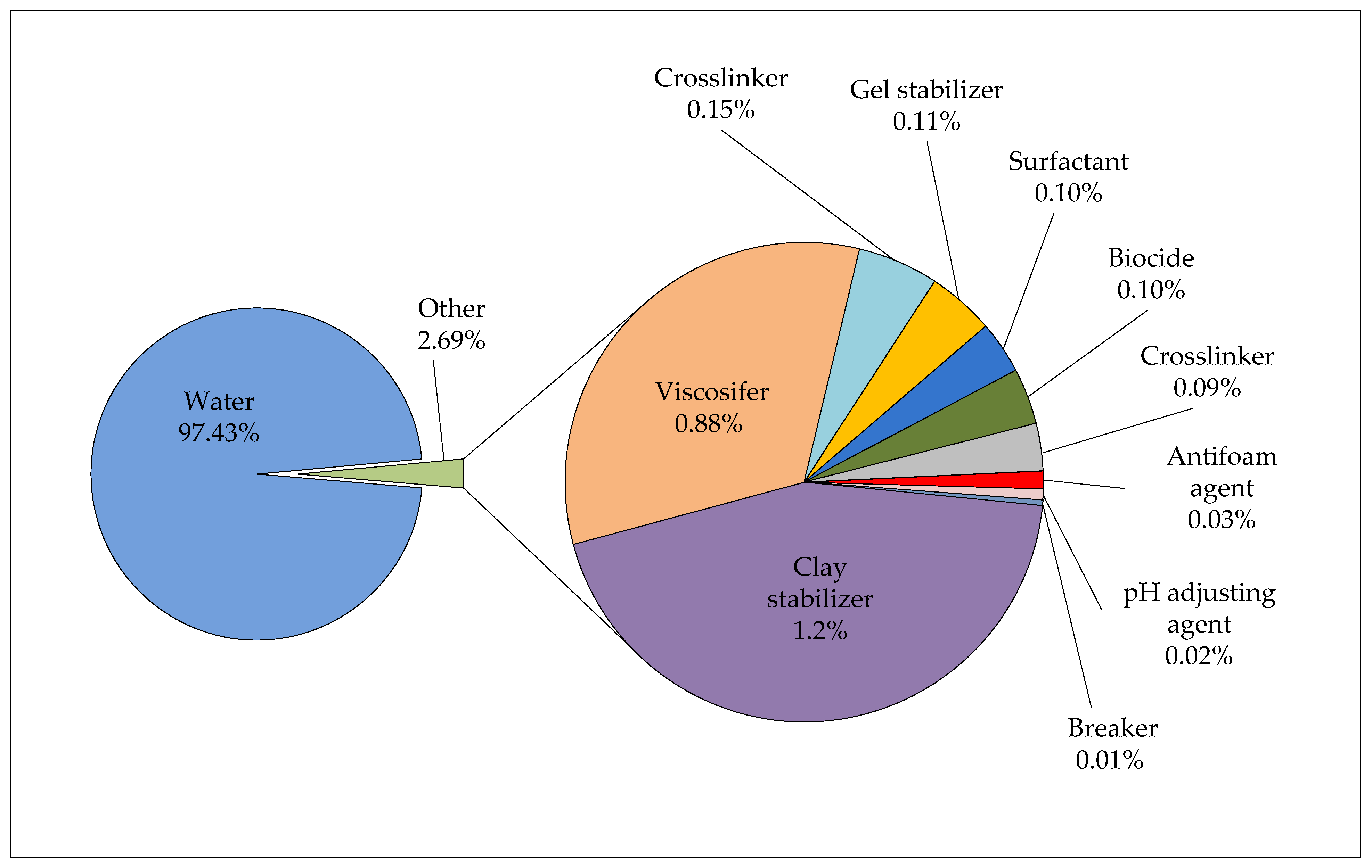
Table 1.
Fracturing fluid testing.
| Fracturing Fluid Testing | |
|---|---|
| Test | Description |
| Rheology—Model 50 | HTHP rheology up to 204 °C and 10.3 MPa. Used for standard crosslinked gel testing (Standard ISO Testing). |
| HTHP rheology—Model 7600 | HTHP rheology up to 316 °C and 276 MPa. |
| Linear gel rheology | Ambient pressure rheology for non-crosslinked fluids such as base linear gels. Temperature up to 88 °C. |
| Viscosity and breaker profiles | Constant shear testing performed on model 50 or model 7600 (depending on temperature and pressures desired) to determine the viscosity profile or breaker effectiveness vs. time. |
| Regained permeability | Testing to determine the percentage of permeability reduction a fracture fluid could potentially cause as a result residual fluid left in the formation. |
Table 2.
Water analysis [3].
Table 2.
Water analysis [3].
| Water Analysis | ||
|---|---|---|
| Parameter | Required Value | Range of Values for Water Used in Croatia |
| pH | <8 | 5.7–7.9 |
| Iron (mg/L as Fe) | <10 | <0.005–9.64 |
| Total Hardness (mg/L as Ca, Mg) | <500 | 42.3–443.35 |
| Chloride (mg/L as Cl) | <1000 | 0.071–63 |
| Sulfate (mg/L as SO4) | <100 | 0.045–70 |
| Salts (mg/L) | <1.5 | 0.1–104 |
| Bicarbonate (mg/L as CaCO3) | <600 | 13.7–634.6 |
| Density (kg/dm3) | <1.005 | 0.9998–1.0009 |
Table 3.
Proppant analysis.
| Proppant Analysis | |
|---|---|
| Test | Description |
| Proppant conductivity | Short- and long-term proppant conductivity. |
| Proppant UCS | Determines unconfined compressive strength (UCS) of proppant (for resin-coated proppants). |
| Composite sieve analysis | Determines the gradation of a sample. Sieve sizes include applicable sizes through number 200 mesh. |
| Sphericity and roundness | Characterizes the physical appearance of proppant. |
| Crush resistance | The strength of proppant is determined by quantifying the amount of proppant crushed at a given stress. |
| Turbidity | Determines the amount of suspended particles or fine matter present in fracture sand by measuring the optical scattering and absorption of light from particulate matter suspended in a wetting fluid. |
| Bulk density | Describes the mass of proppant that fills a unit volume, including both proppant and porosity. |
| Apparent density | Measured with a low viscosity fluid that wets the proppant particle surface. It takes into account the volume of pore space inaccessible to the fluid. |
| Absolute density | Density of the proppant, excluding the inaccessible pores in the proppant and void spaces between the proppant itself. |
| Acid solubility | Often used to indicate and quantify the presence of impurities in fracture sand. |
| Simulated fracture window | A large-scale physical model consisting of two pieces of Plexiglas held 6.35 mm apart. This is used to visually observe fluid flow through a simulated 6.35 mm fracture. Useful for comparative testing between two fracture fluids. Properties such as proppant transport capabilities, for example, can be tested and qualitatively and quantitatively measured. The model is 0.91 m tall and 2.44 m long. |
Table 4.
Water-based fracturing fluids. HPG: hydroxypropyl guar; HEC: hydroxyethyl cellulose; CMHPG: carboxymethyl hydroxypropy1 guar; CMHEC: carboxymethyl hydroxyethyl cellulose.
Table 4.
Water-based fracturing fluids. HPG: hydroxypropyl guar; HEC: hydroxyethyl cellulose; CMHPG: carboxymethyl hydroxypropy1 guar; CMHEC: carboxymethyl hydroxyethyl cellulose.
| Base Fluid | Fluid Type | Composition | Used for |
|---|---|---|---|
| Water | linear gel | water, guar, HPG, HEC, CMHPG | short fractures, low temperature |
| crosslinked gel | water, crosslinker, guar, HPG, CMHPG or CMHEC | long fractures, high temperature | |
| slickwater | water, sand, additives | short and narrow fractures, low temperature | |
| viscoelastic surfactant gel (micellar) | water, electrolyte, surfactant | moderate long fractures, moderate high temperature | |
| Advantages | |||
| The most commonly used fracturing fluids, their behavior in well conditions is the best researched, they are reasonably priced, they can be designed for different types of reservoir rocks, and they can be applied in a wide range of temperatures. | |||
| Disadvantages | |||
| Water can cause severe emulsions that can lead to emulsion blockage cases, as well as water blockage cases in tight gas wells. There is a risk of inorganic scale precipitation near the wellbore, which can cause alterations to relative permeability, can increase near wellbore skin and reduce production rates. | |||
Table 5.
Oil-based fracturing fluids.
| Base Fluid | Fluid Type | Composition | Used for |
|---|---|---|---|
| Oil | linear gel | oil, gelling agent | short fractures, water-sensitive formations |
| crosslinked gel | oil, gelling agent, crosslinker | long fractures, water-sensitive formations | |
| emulsion | water, oil, emulsifier | moderate length fractures, good fluid loss control | |
| Advantages | |||
| Water usage is very reduced or completely eliminated. Fewer (or no) chemical additives are required. Flaring and truck traffic is reduced. There is a lower viscosity, density and surface tension of the fluid, which results in lower energy consumption during fracturing. They are compatible with shale reservoirs. There is no fluid loss. They increase the productivity of the well. Recovery rates (up to 100%) are possible. The cleanup is very rapid, often within 24 h. | |||
| Disadvantages | |||
| They are potentially riskier than other fluids and more suitable in sparsely populated areas because they require large quantities of flammable propane. There is a higher investment cost. Their success relies on the formation ability to return most of the propane back to the surface to reduce the overall cost. | |||
Table 6.
Acid-based fracturing fluids.
| Base Fluid | Fluid Type | Composition | Used for |
|---|---|---|---|
| Acid | linear gel | acid, guar or HPG | short fractures, carbonate formations |
| crosslinked gel | acid, crosslinker, guar or HPG | long and wide fractures, carbonate formations, | |
| emulsion | acid, oil, emulsifier | moderate length fractures, carbonate formations | |
| The application of acid fracturing is confined to carbonate reservoirs and is never used to stimulate sandstone, shale, or coal-seam reservoirs. | |||
Table 7.
Alcohol-based fracturing fluids.
| Base Fluid | Fluid Type | Composition | Used for |
|---|---|---|---|
| Alcohol | methanol and water mixture or 100% methanol | methanol and water | low permeability reservoirs with high clay content, low formation pressure |
| Advantages | |||
| Water usage is very reduced or completely eliminated. Methanol is not persistent in the environment (it biodegrades readily and quickly under both anaerobic and aerobic conditions and photo-degrades relatively quickly). It has excellent fluid properties: a high solubility in water, low surface tension and high vapor pressure. It is a very good fluid for water-sensitive formations. | |||
| Disadvantages | |||
| Methanol is a dangerous substance to handle because it has a low flash point—hence is easier to ignite—a large range of explosive limits, high vapor density and invisibility of the flame. | |||
Table 8.
Foam-based fracturing fluids.
| Base Fluid | Fluid Type | Composition | Used for |
|---|---|---|---|
| Foam | water-based | water, foamer, N2 or CO2 | low pressure formations |
| acid-based | acid, foamer, N2 | low pressure, carbonate formations | |
| alcohol-based | methanol, defoamer, N2 | low pressure, water-sensitive formations | |
| CO2-based | liquid CO2 + N2 | low pressure formations | |
| Advantages | |||
| Water usage is reduced (or completely eliminated in the case of CO2-based foams). There is a reduced amount of chemical additives. There is a reduction in formation damage. There is a better cleanup of the residual fluid. | |||
| Disadvantages | |||
| There is a low proppant concentration in fluid, hence decreased fracture conductivity. There are higher costs. The foams have a difficult rheological characterization, i.e., flow behavior is difficult to predict. A higher surface pumping pressure is required. | |||
Table 9.
Energized fracturing fluids.
| Base Fluid | Fluid Type | Composition | Used for |
|---|---|---|---|
| Energized Fluid | liquefied carbon dioxide | CO2 | low permeability reservoirs, water-sensitive formations, low formation pressure |
| liquefied nitrogen | N2 | ||
| liquefied helium | He | ||
| liquefied natural gas | LNG (butane and/or propane) | ||
| Advantages | |||
| There are potential environmental advantages: water usage is very reduced or completely eliminated, few or no chemical additives are required, and some level of CO2 sequestration is achieved. There is a reduction in formation damage (reduction in permeability and capillary pressure damage by reverting to a gaseous phase; no swelling induced) [27]. They form more complex micro-fractures, which can connect many more natural fractures greatly, increasing maximally the fracture conductivity [55]. They enhance gas recovery by displacing the methane adsorbed in the shale formations [55]. The evaluation of a fracture zone is almost immediate because of rapid cleanup. The energy provided by CO2 results in the elimination of all residual liquid left in the formation from the fracturing fluid. There is a better cleanup of the residual fluid, so a smaller mesh proppant can be used and supplies adequate fracture conductivity in low permeability formations. The use of a low viscosity fluid results in more controlled proppant placement and higher proppant placement within the created fracture width. | |||
| Disadvantages | |||
| The main disadvantages arise from the fluid’s low viscosity. The proppant concentration must be lower and proppant sizes smaller, which decrease fracture conductivity. CO2 must be transported and stored under pressure (typically 2 MPa) and temperature (−30 °C). Another disadvantage is the corrosive nature of CO2 in the presence of H2O. There are unclear (potentially high) treatment costs. | |||
Table 10.
Emulsion-based fracturing fluids.
| Base Fluid | Fluid Type | Composition | Used for |
|---|---|---|---|
| Emulsion | water–oil emulsion | water + oil | water-sensitive formations, unconventional (low permeability) formations, but no direct usage for shale gas stimulation |
| CO2–methanol | CO2 + water + methanol | ||
| others | - | ||
| Advantages | |||
| Depending on the type of components used to formulate the emulsion, these fluids can have potential advantages such as: water usage is very reduced or eliminated, fewer (or no) chemical additives are required, the increased productivity of the well, better rheological properties, and fluid compatibility with shale reservoirs. | |||
| Disadvantages | |||
| There are potentially higher costs. The costs could potentially be higher when compared to water-based hydraulic fracturing, depending on the type of emulsion formulation. | |||
Table 11.
Newly developed synthetic fracturing fluids.
| Fluid Name | Fluid Composition | Additive Description | Purpose of Testing | Performed Tests | Results |
|---|---|---|---|---|---|
| SM-VF (supramolecular viscoelastic fluid) [23] | 0.8% wt supramolecular polymer thickener (SMPT), 0.5% wt viscoelastic surfactant (VES), 2% wt KCl | SMPT is synthesized by monomers such as acrylamide, sodium acrylate and amide monomer. Used VES is betaine zwitterionic. | Developing very efficient crosslinks in gel that can be advantages in the elastic and viscous properties of fluid. | The measurement of rheological properties, proppant suspension test, gel breaking property test, and formation damage. | Fluid is stable at 150 °C, has better suspension ability than guar-based fluids, extremely efficient crosslinking, good cleanup and low formation damage. |
| Terpolymer fluid [24] | Synthetic acrylamide-based anionic terpolymer gelatinizer, zirconium crosslinked with persulfat as the gel breaker. | - | Developing the fluid for fracturing ultra-depth (>5000 m) well with an ultra-high temperature (211 °C) in China. | The measurement of rheological properties, proppant suspension test, filtration, gel breaking property test and formation damage. | After fracturing, the production of hydrocarbons is encouraged with 73 m3/d oil and 10.5 ∙ 104 m3/d gas. |
| Synthetic polymer fluid for ultra-high temperatures [25] | Synthetic polymer as a gelling agent, zirconium as the crosslinker, oxdizing breaker and “green” temperature stabilizer. | - | Developing an ultra-high temperature hydraulic fracturing fluid system. | The hydration of gelling agent, measurement of rheological properties, gel breaking property test, test of fluid loss, and retained conductivity test. | Fluid demonstrates stability to 230 °C, has acceptable fluid loss, and shows controlled breaking with low formation damage. |
| Hybrid dual-polymer hydraulic fracturing fluid [60,61] | Guar derivative and a polyacrylamide-based synthetic polymer crosslinked with a metallic crosslinker. | Emulsion form composed of acrylamide, acrylic acid, 2-acrylamido-2-methylpropane sulfonic acid. | Maintaining the thermal stability of fracturing fluids (up to 204 °C) at a lower polymer loading. | The measurement of rheological properties, and proppant-carrying properties. | By the addition of synthetic polymer to CMHPG, a fluid that is stable up to 176 °C was generated; a dual-polymer system with lower polymer loading can reduce material cost and damage in the generated fractures. |
| A new high temperature polymer fracturing fluid [62] | A novel non-residual fracturing fluid developed through analyzing the structure of polymer 2-acrylamido-2-methylpropanesulfonic acid. | Thickening agents, cleanup additive, the clay stabilizer, the thermal stabilizer, zirconium crosslinking agent. | Developing the fracturing fluid for hydraulic fracturing in high-temperature low-permeability reservoirs. | Shear stability of polymers, high-temperature rheology, gel breaking testing, and formation damage. | Synthetic polymer fracturing fluid has good shear stability, and high-temperature rheology measurement shows that the polymer fracture fluid can be used up to 170 °C. |
| High Elasticity and Low Viscosity (HELV) Fracturing Fluid [63] | - | HELV is a quaternary polymer designed by copolymerizing acrylamide, acrylic acid, 4-isopropenylcarbamoyl-benzene sulfonic acid and N-(3-methacrylamidopropyl)-N,N-dimethyldodecan-1-aminium. | Fracturing fluid which could be an alternative for the development of oil and gas resources. | Viscoelasticity measurements, thixotropy, and dynamic sand suspension. | HELV, because of its excellent elasticity, added in the fracturing fluid improved viscosity, proppant suspension capacity and pipeline and liquid friction. |
Table 12.
Fracturing fluid additives.
| Fracturing Fluid Additives | ||
|---|---|---|
| Additive | Typical products | Function |
| Water | fresh, salt or produced water | Base (carrier) fluid |
| Acid | hydrochloride or acetic acid | Dissolves minerals |
| Biocide | amides, aldehydes, quaternary amines, chlorine dioxide | Kills bacteria |
| Breaker | calcium or magnesium peroxide, hydrochloride or acetic acid | Causes gel degradation and reduces fluid viscosity |
| Clay stabilizer | potassium chloride, sodium chloride, calcium chloride, polyamines | Prevents clay swelling |
| Crosslinker | borate, titanium, zirconium, aluminum | Increases the molecular weight of the polymer by crosslinking the polymer backbone into a 3-D structure. Increases the base viscosity of the linear gel. Increases the elasticity and proppant transport capability of the fluid. |
| Iron chelating agent | Citric acid, acetic acid, thioglycol acid, sodium erithorbate | Keeps iron in solution |
| pH adjusting agent/ buffer | sodium hydroxide, sodium carbonate, potassium hydroxide, potassium carbonate, acetic acid formic acid, magnesium oxide | Controls the pH |
| Friction reducer | polyacrylic acid, polyacrylamide, ethylene glycol, methanol | Reduces the friction |
| Gelling agent (Viscosifer) | guar and its derivatives (HPG, CMG, CMHPG), cellulose and its derivatives (HEC, CMHEC), surfactants | Increases the viscosity |
| Scale inhibitor | ethylene glycol, methanol, ethylene diamine tetraacetic acid (EDTA) | Prevents scale in tubing and formation |
| Surfactant | ethanol, naphthalene, methanol, isopropyl alcohol, lauryl sulfate | Lowers surface tension |
| Proppant | silica sand, resin-coated sand, ceramic proppant | Keeps fractures open |
Table 13.
Proppant’s properties.
| Proppant | Density (kg/m3) | Compressive Strength (bar) | Max. Work Depth (m) |
|---|---|---|---|
| Silica sand | 2650 | 414 | 2500 |
| Resin-coated sand | 1500 | 552 | 2500–3000 |
| Ceramic proppants | 3500 | 690 | >3000 |
Table 14.
Geological and well design data for the selected wells. W-1–W-4: well 1–well 4.
| Well Name | ||||
|---|---|---|---|---|
| W-1 | W-2 | W-3 | W-4 | |
| Geological data | ||||
| Depth, m | 2823 | 2776 | 4646 | 3410 |
| Reservoir fluid | gas condensate | gas condensate | gas condensate | gas condensate |
| Production intervals depth, m | 2529–2561 | 2739–2776 | 3782–3818.5 | 3298–3392 |
| Lithology | limestone | limestone | quartzite | siltstone |
| Porosity, % | 12–14 | 12–14 | 10 | 1–4 |
| Permeability, 10−3 µm2 | 8.4 | 1.3 | 0.021 | 0.1 |
| Reservoir pressure, bar | 255 | 255 | 332 | 480 |
| Reservoir temperature, °C | 146 | 149 | 190 | 178 |
| HF goals | Enable production with lower drawdown | Remove skin and increase productivity index | Increase wellhead pressure and enable gas production | Remove skin and increase productivity index |
| Well design | ||||
| Well path | Vertical | Directional | Vertical | Vertical |
| Production casing dia, mm (inch) | 177.8 (7) | 177.8 (7) | 177.8 (7) | 177.8 (7) |
| Liner dia, mm (inch) | 127 (5) | 144.3 (4.5) | - | - |
| Open hole dia, mm (inch) | - | 95 (3.75) | - | - |
| Tubing dia, mm (inch) | 88.9 (3.5) | 88.9 (3.5) | 73.02 (2.785) | 88.9 (3.5) |
Table 15.
Fracturing fluid composition.
| Fracturing Fluid Composition | ||||
|---|---|---|---|---|
| Additive, Unit | Wells | |||
| W-1 | W-2 | W-3 | W-4 | |
| Total Quantity | ||||
| Proppant, kg | 30,000 | 21,000 | 151,500 | 150,000 |
| Gelling Agent, kg | 1135 | 887 | 12,297 | 11,600 |
| Crosslinker, l | 600 | 460 | 1750 | 1750 |
| Surfactant, l | 260 | 250 | 510 | 708 |
| Clay Control, l | 520 | 500 | 1020 | 1160 |
| HT breaker, kg | 44.5 | 31.3 | 129 | 225 |
| HT Encapsulated breaker, kg | 39 | 22 | 125 | 140 |
| HT Stabilizer, kg | 49 | 53.5 | 285 | 450 |
| Delay Agent, kg | 67 | - | - | - |
| Stabilizer, l | 160 | 230 | - | - |
| pH Buffer, kg | 99 | 71.7 | - | - |
| LT friction reducer, kg | 48 | 48 | - | - |
| MT friction reducer, kg | 460 | 222 | 127 | - |
| HT friction reducer, kg | - | - | - | 127 |
| Acetic Acid (10%), kg | - | - | 434 | 1250 |
| Dry Guar Polymer, kg | - | - | 100 | - |
HT-high temperature; MT-medium temperature; LT-low temperature.
Table 16.
Main hydraulic fracturing summary. FCD: fracture conductivity.
| Well Name | ||||
|---|---|---|---|---|
| W-1 | W-2 | W-3 | W-4 | |
| Water-based gel, m3 | 191.7 | 140.4 | 445.3 | 571.4 |
| Proppant, kg | 30,000 | 21,000 | 151,000 | 150,000 |
| Maximum frac pressure, bar | 373 | 390 | 510 | 588 |
| Maximum slurry rate, m3/min | 3.5 | 3.5 | 4.0 | 4.0 |
| FCD, dimensionless | 171 | 5149 | 147 | 17.2 |
Table 17.
Well production before and post HF.
| Well | Before HF | Post HF | ||||||
|---|---|---|---|---|---|---|---|---|
| Qg (m3/d) | Qc (m3/d) | Qw (m3/d) | Pwh (bar) | Qg (m3/d) | Qc (m3/d) | Qw (m3/d) | Pwh (bar) | |
| W-1 | 280,000 | 28 | 7 | 120 | 315,000 | 38 | 8 | 125 |
| W-2 | 15,000 | 2 | 140 | 65 | 55,000 | 7 | 104 | 102 |
| W-3 | 2400 | 1 | 1 | 31 | 28,000 | 17 | 22 | 45 |
| W-4 | 1200 | 0 | 0 | 20 | 30,000 | 2 | 60 | 40 |
| Total | 298,600 | 31 | 148 | - | 428,000 | 64 | 194 | - |
Publisher’s Note: MDPI stays neutral with regard to jurisdictional claims in published maps and institutional affiliations. |
© 2021 by the authors. Licensee MDPI, Basel, Switzerland. This article is an open access article distributed under the terms and conditions of the Creative Commons Attribution (CC BY) license (http://creativecommons.org/licenses/by/4.0/).
Share and Cite
MDPI and ACS Style
Gaurina-Međimurec, N.; Brkić, V.; Topolovec, M.; Mijić, P. Fracturing Fluids and Their Application in the Republic of Croatia. Appl. Sci. 2021, 11, 2807. https://0-doi-org.brum.beds.ac.uk/10.3390/app11062807
AMA Style
Gaurina-Međimurec N, Brkić V, Topolovec M, Mijić P. Fracturing Fluids and Their Application in the Republic of Croatia. Applied Sciences. 2021; 11(6):2807. https://0-doi-org.brum.beds.ac.uk/10.3390/app11062807
Chicago/Turabian StyleGaurina-Međimurec, Nediljka, Vladislav Brkić, Matko Topolovec, and Petar Mijić. 2021. "Fracturing Fluids and Their Application in the Republic of Croatia" Applied Sciences 11, no. 6: 2807. https://0-doi-org.brum.beds.ac.uk/10.3390/app11062807
Note that from the first issue of 2016, this journal uses article numbers instead of page numbers. See further details here.