
Fuzzy Logic-Based Duty Cycle Controller for the Energy Management System of Hybrid Electric Vehicles with Hybrid Energy Storage System

 ,
,
Abstract
:1. Introduction
1.1. Background and Motivation
1.2. Literature Review
1.3. Research Contribution and Objectives
1.4. Paper Organization
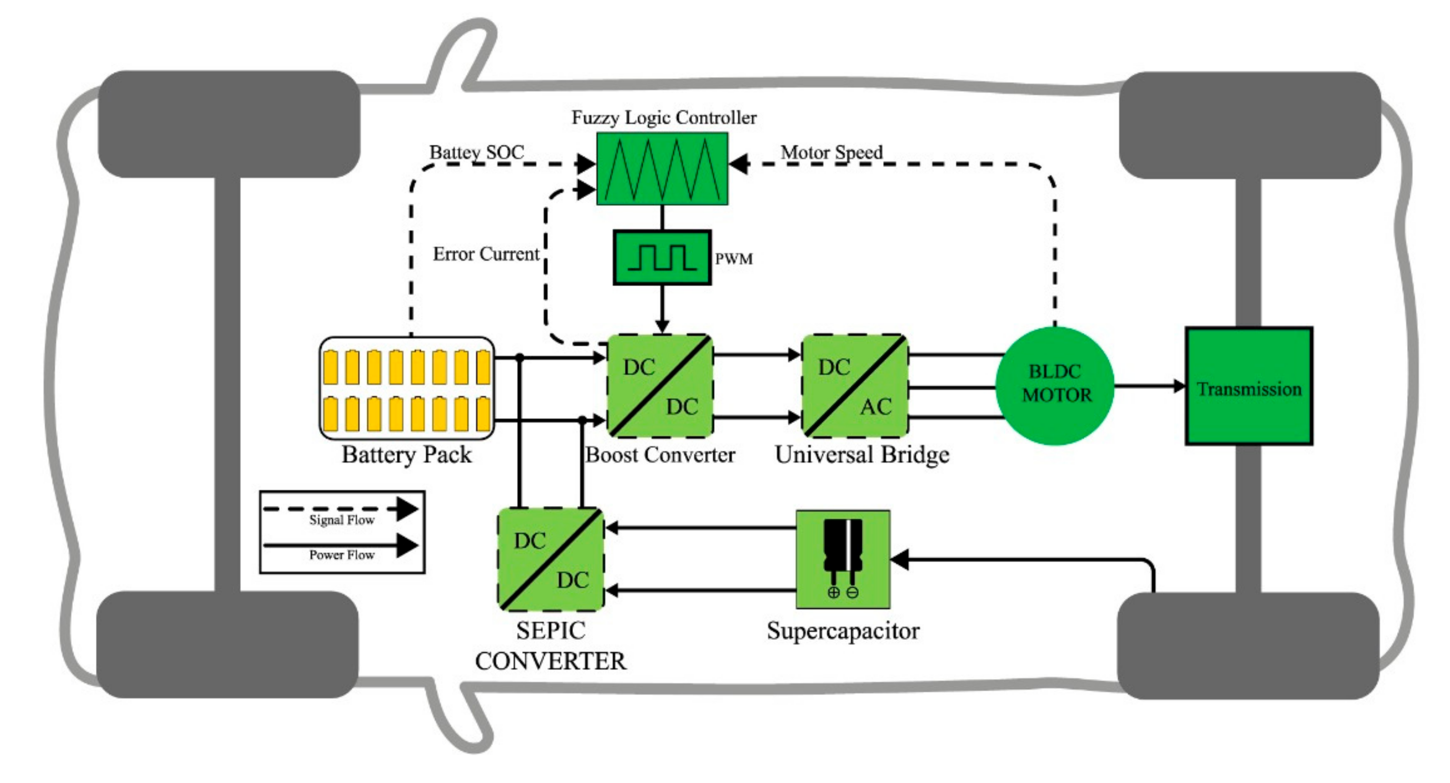
2. Proposed System Model
3. Components Modeling of Proposed Design
3.1. DC–DC Boost Converter
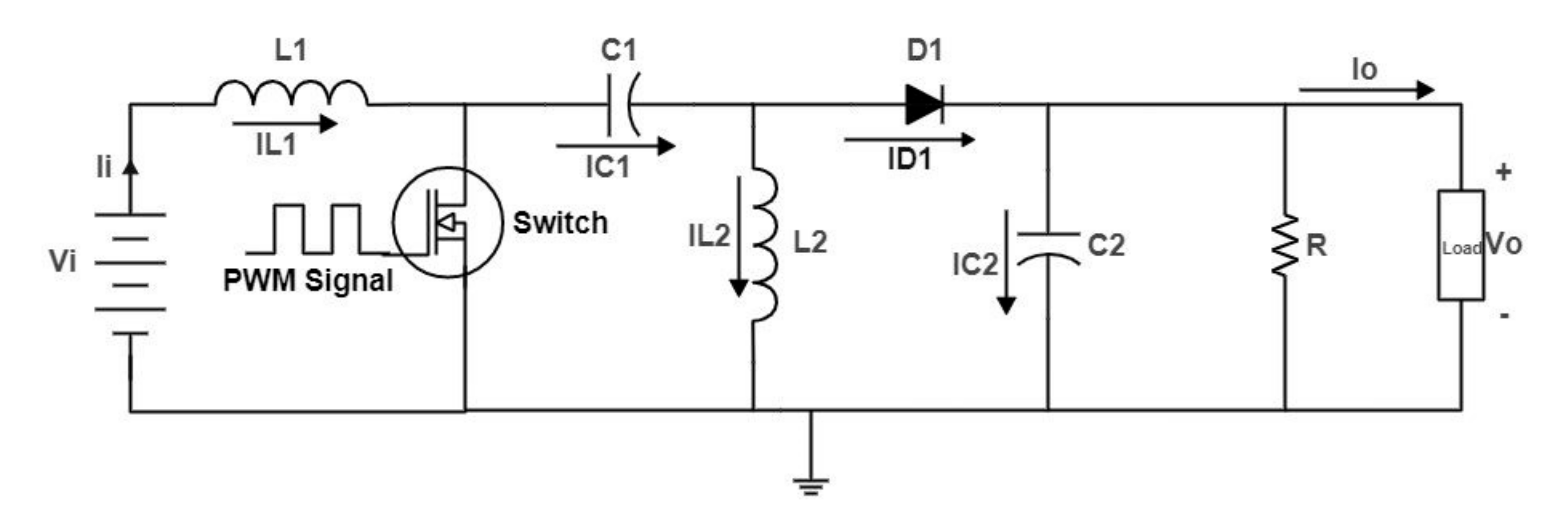
3.2. DC–DC SEPIC Converter
4. Energy Management System Based on Fuzzy Logic Controller (FLC)
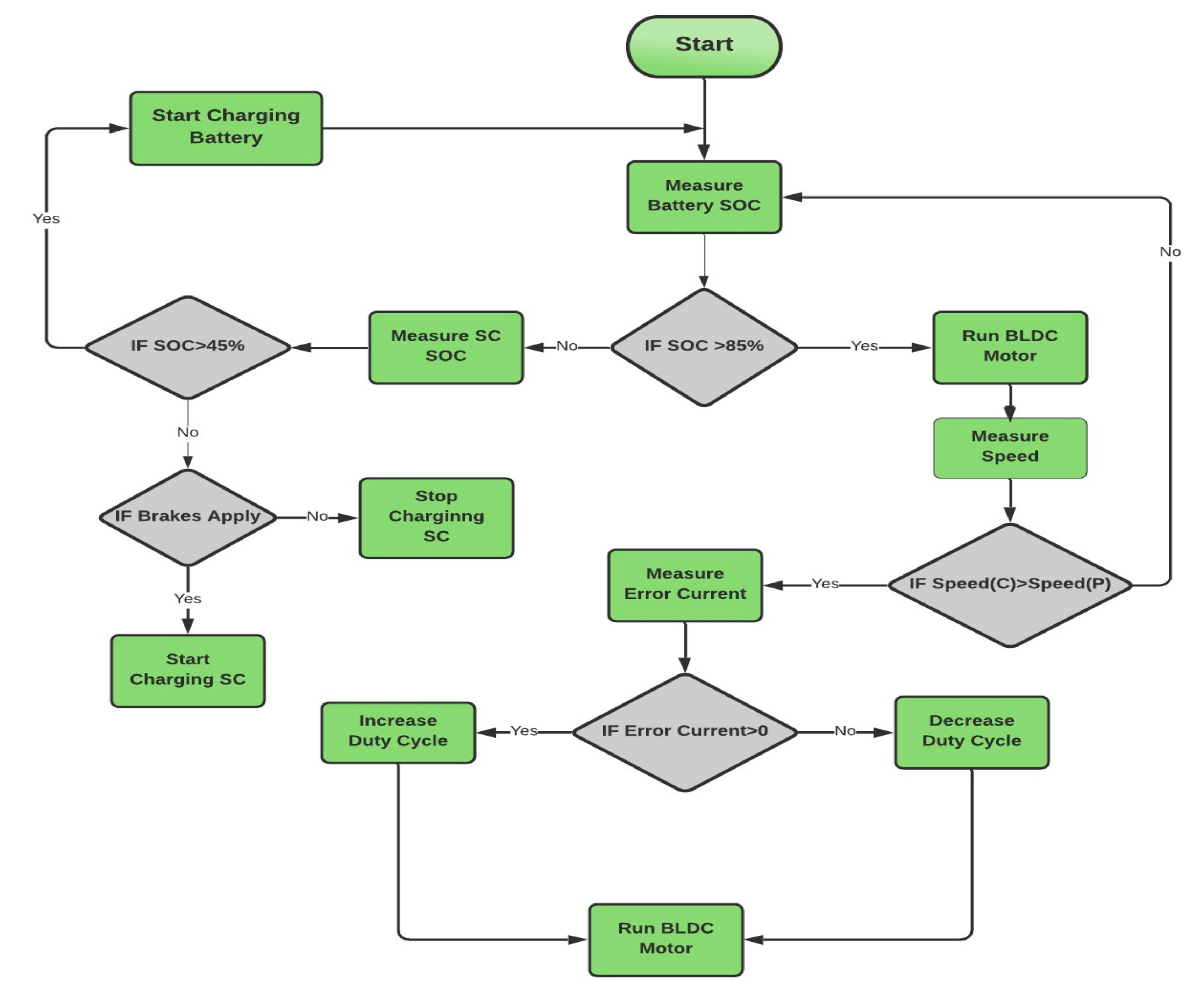
4.1. Ultra Power Transfer Algorithm
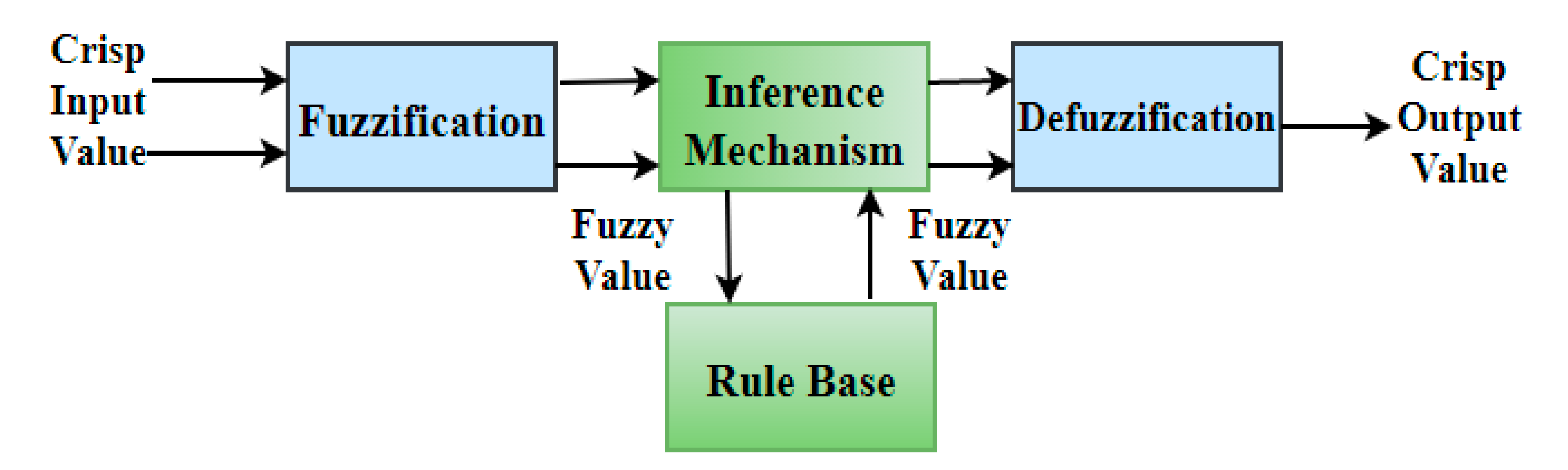
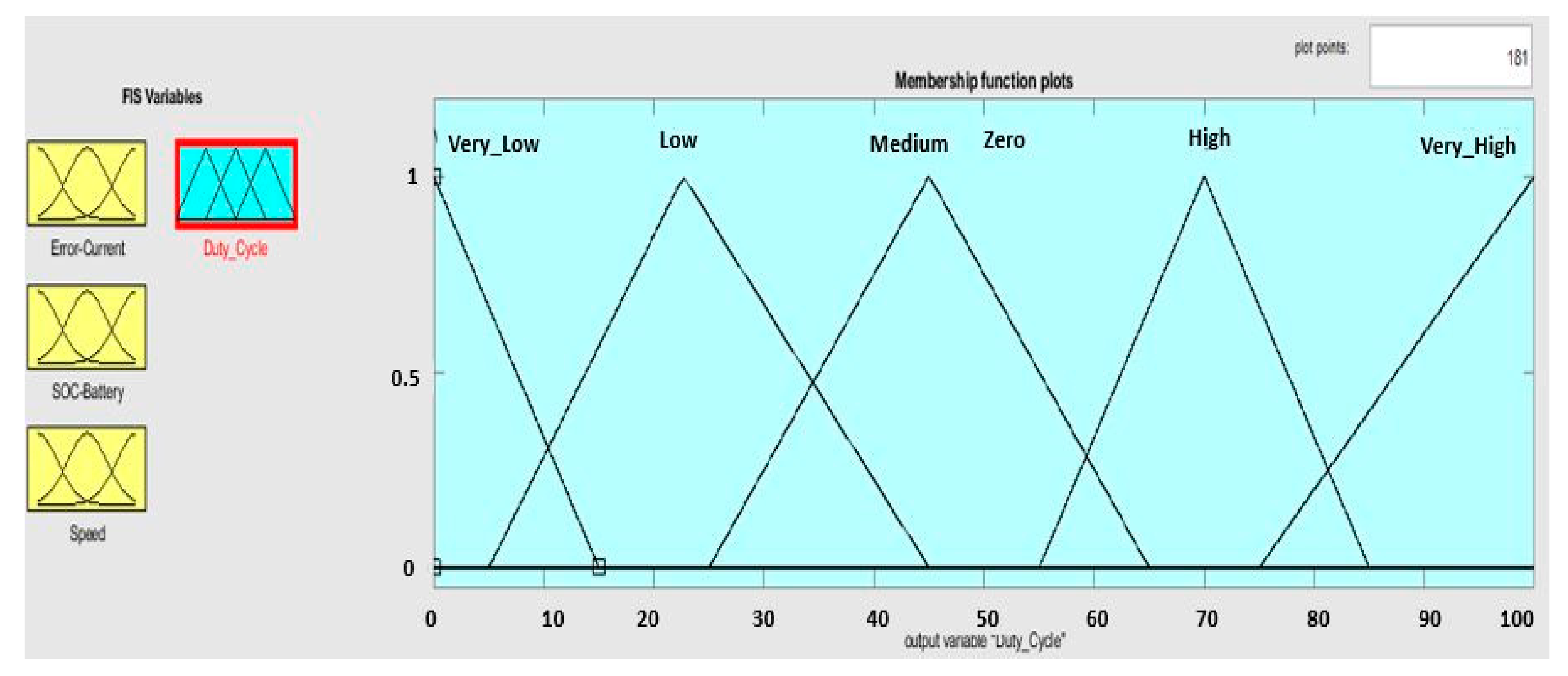
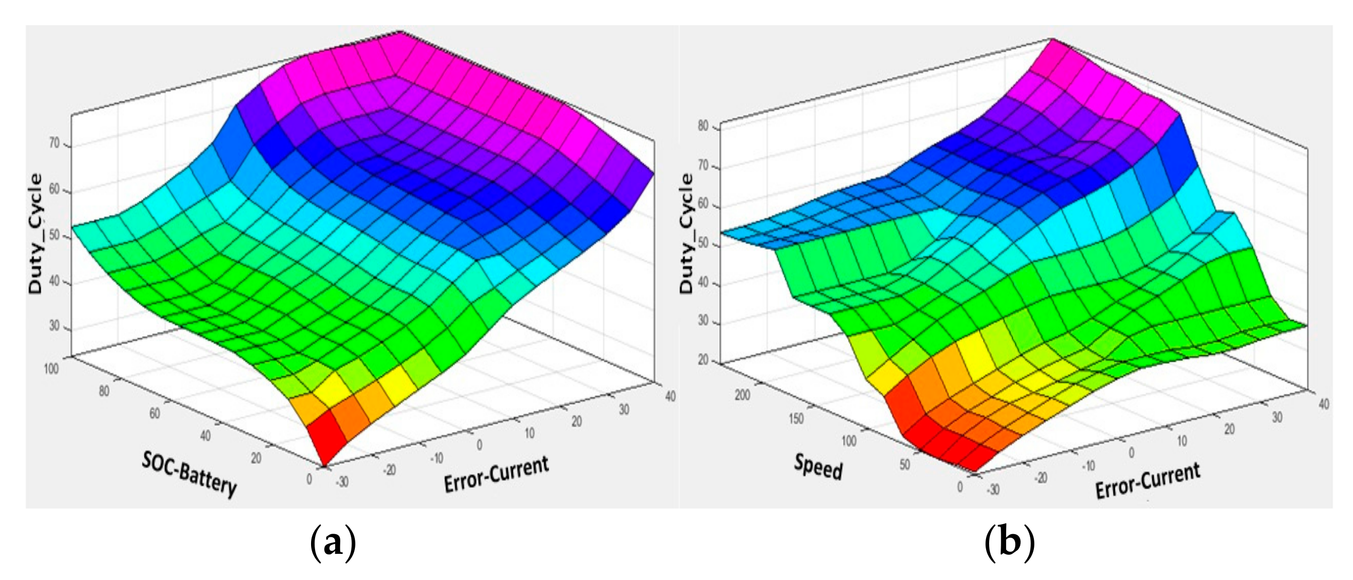
4.2. Fuzzy Logic Controller (FLC)
- 1:
- Gaussian Fuzzifier
- 2:
- Singleton Fuzzifier
- 3:
- Triangular/Trapezoidal Fuzzifier
- I.
- Mamdani FIS
- II.
- Takagi–Sugeno–Kang FIS
- 1:
- Error between the input and output current of the boost converter.
- 2:
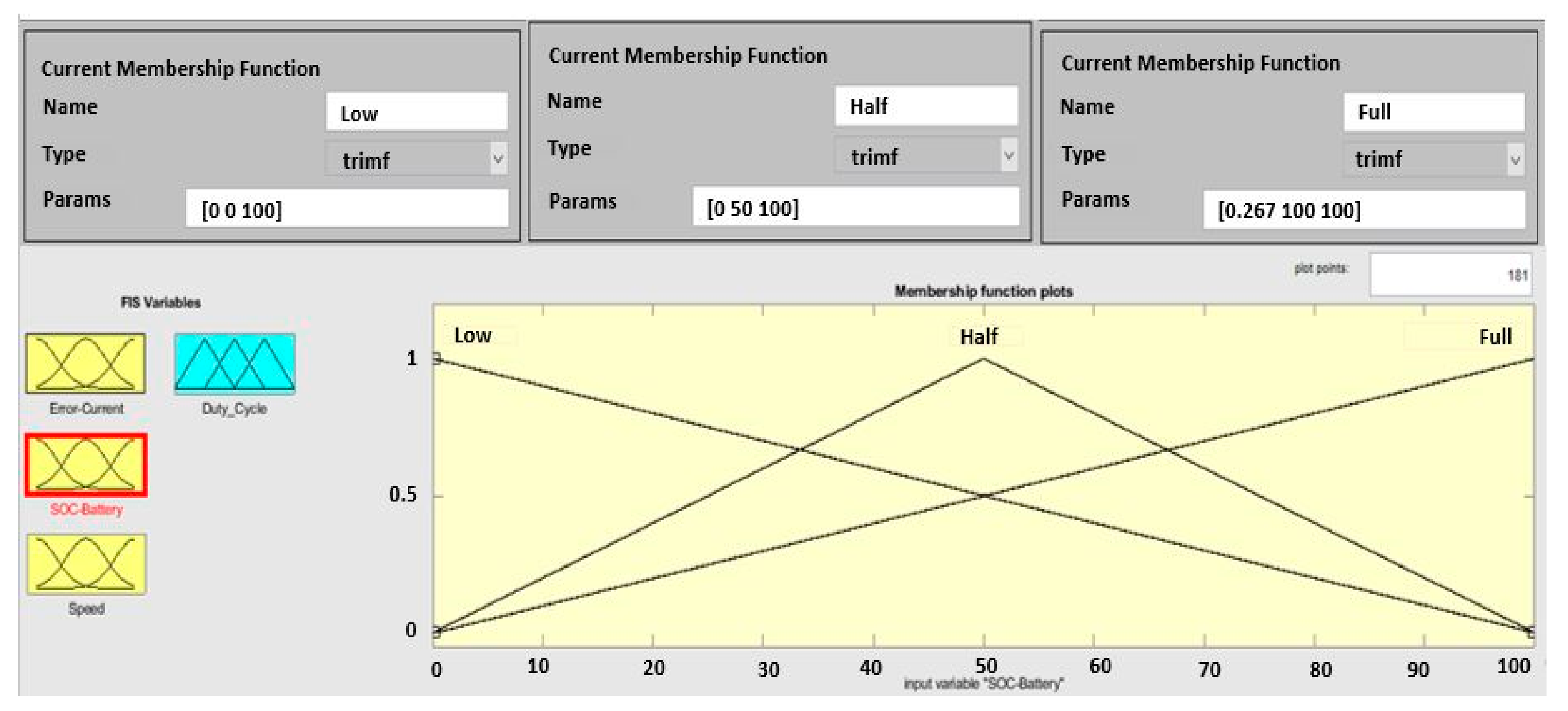
- SOC of the battery.
- 3:
- Speed of the BLDC motor.
5. Comparison between Fuzzy Logic Controller (FLC) and PI Controller-Based Energy Management System
6. Results and Discussion
- Scenario 1 (constant speed cruise with a constant power supply)
- Scenario 2 (charging of the SC during regenerative mode)
- Scenario 3 (acceleration and deceleration of the vehicle during variable speed)
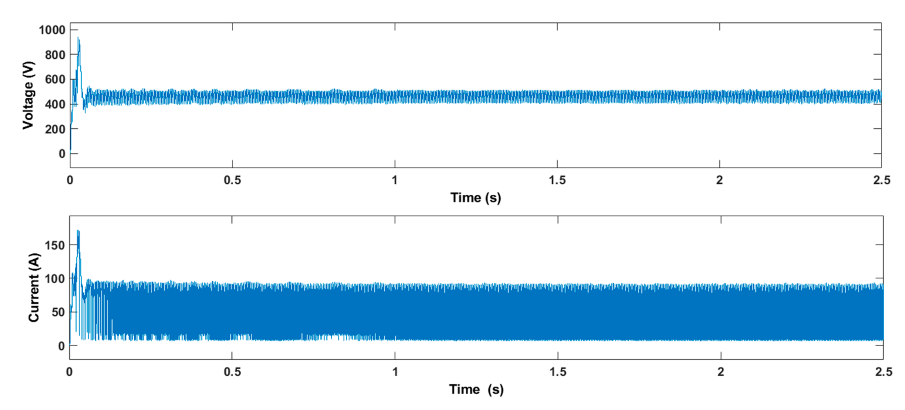
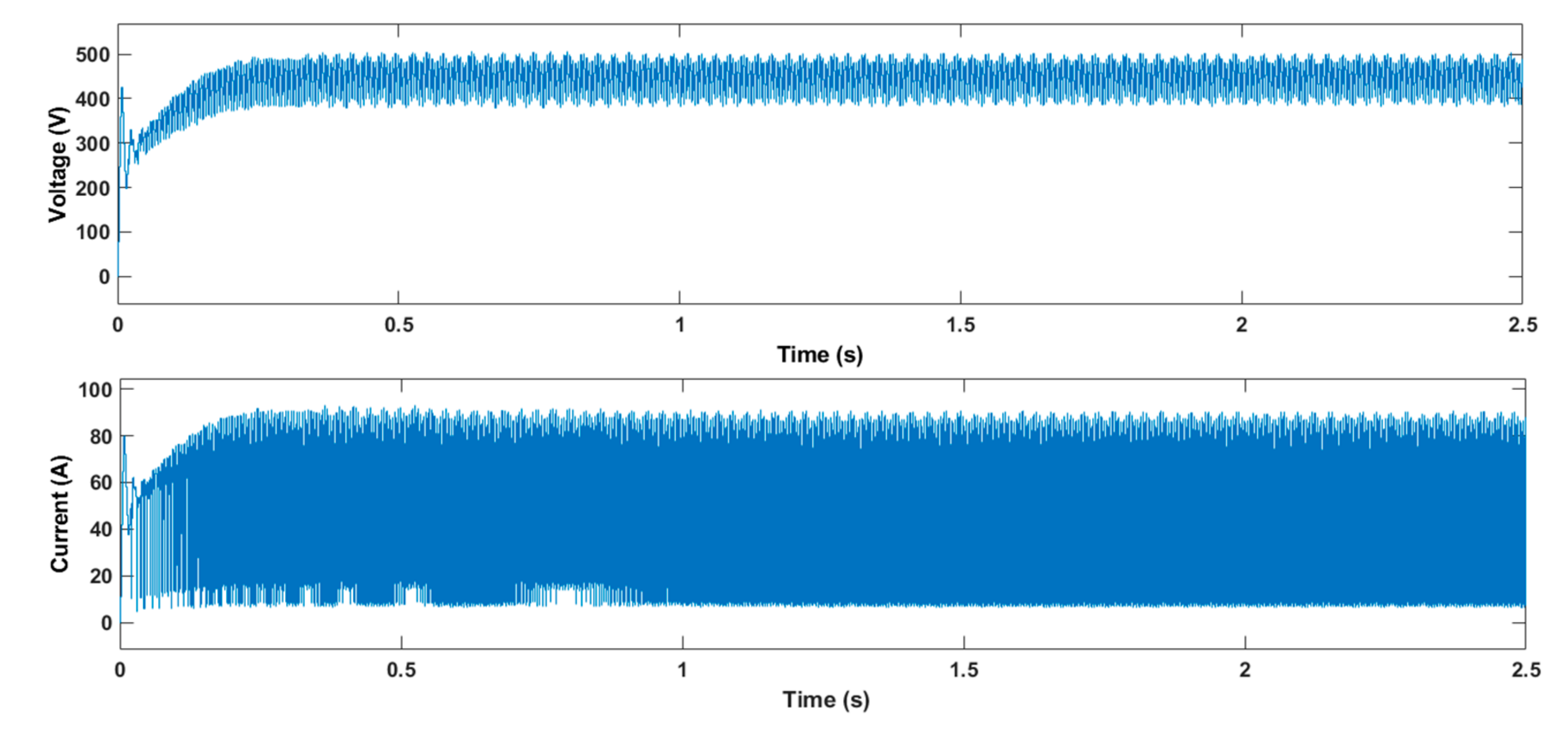
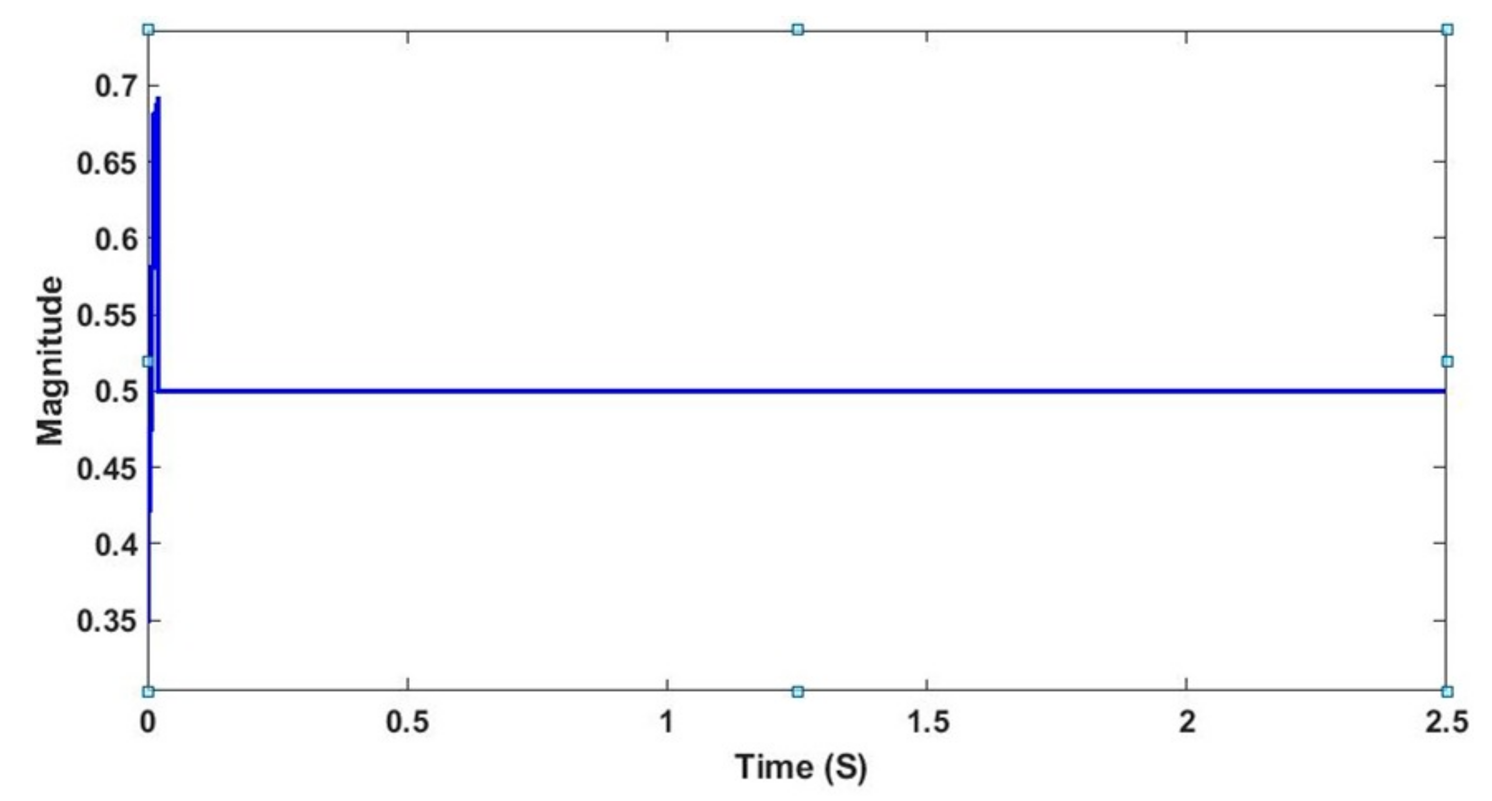
6.1. Scenario 1 (Constant Speed Cruise with Constant Power Supply)
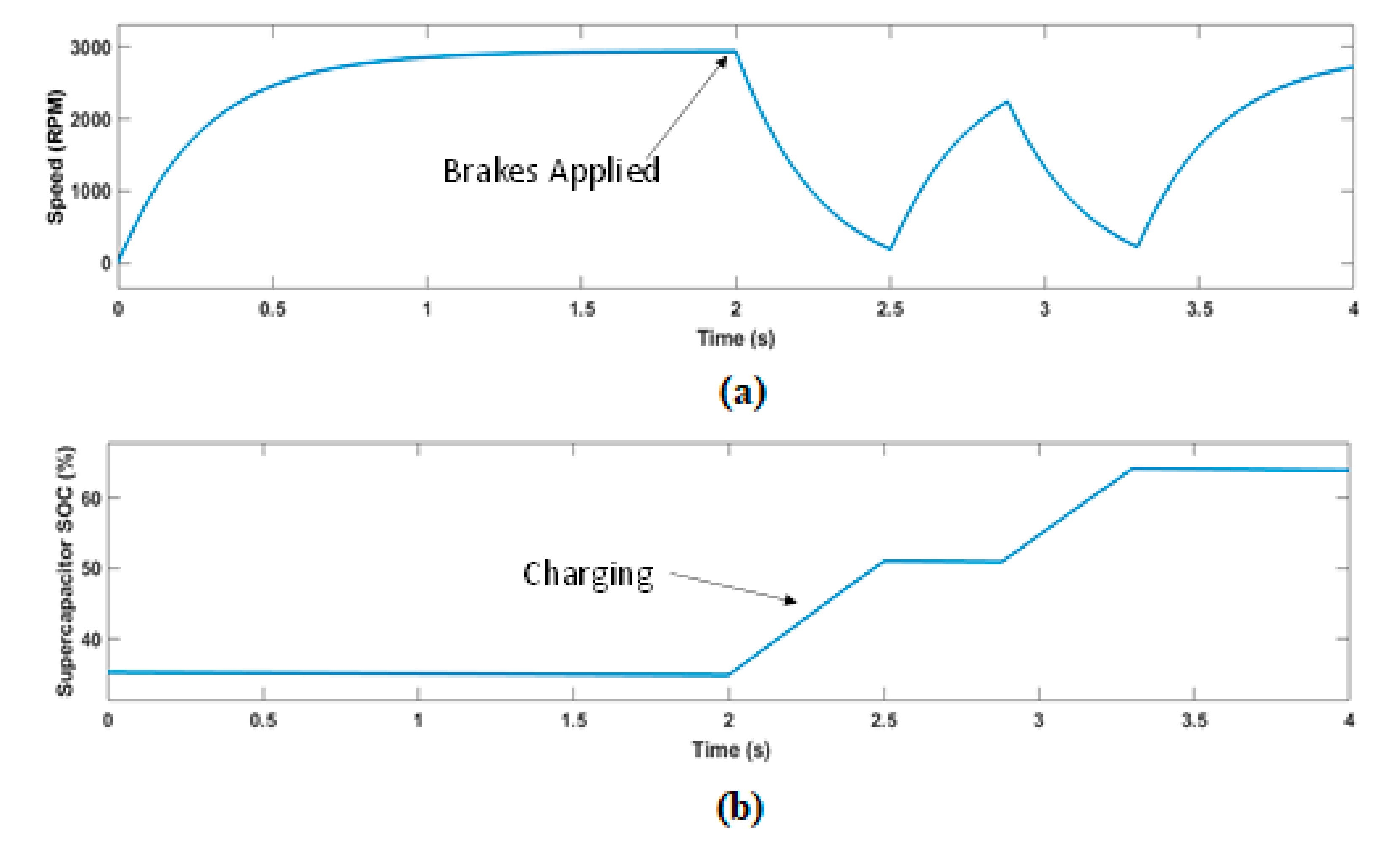
6.2. Scenario 2 (Charging of SC during Regenerative Mode)
6.3. Scenario 3 (Acceleration and Deceleration of Vehicle during Variable Speed)
7. Conclusions
Author Contributions
Funding
Institutional Review Board Statement
Informed Consent Statement
Data Availability Statement
Conflicts of Interest
References
- Chan, C. The state of the art of electric and hybrid vehicles. Proc. IEEE 2002, 90, 247–275. [Google Scholar] [CrossRef] [Green Version]
- Nithya, R.; Sundaramoorthi, R. Design and implementation of SEPIC converter with low ripple battery current for electric vehicle applications. In Proceedings of the 2016 International Conference on Emerging Trends in Engineering, Technology and Science (ICETETS), Pudukkottai, India, 24–26 February 2016; pp. 1–4. [Google Scholar]
- Lv, Y.-M.; Yuan, H.-W.; Liu, Y.-Y.; Wang, Q.-S. Fuzzy logic based Energy management system of battery-ultracapacitor composite power supply for HEV. In Proceedings of the 2010 First International Conference on Pervasive Computing, Signal Processing and Applications, Harbin, China, 17–19 September 2010; pp. 1209–1214. [Google Scholar]
- Sathishkumar, P.; Piao, S.; Khan, M.A.; Kim, D.H.; Kim, M.S.; Jeong, D.K.; Lee, C.; Kim, H.J. A Blended SPS-ESPS Control DAB-IBDC Converter for a Standalone Solar Power System. Energies 2017, 10, 1431. [Google Scholar] [CrossRef]
- Afzal, M.M.; Khan, M.A.; Hassan, M.A.S.; Wadood, A.; Uddin, W.; Hussain, S.; Rhee, S.B. A Comparative Study of Supercapacitor-Based STATCOM in a Grid-Connected Photovoltaic System for Regulating Power Quality Issues. Sustainability 2020, 12, 6781. [Google Scholar] [CrossRef]
- Hussain, S.; Ali, M.U.; Park, G.-S.; Nengroo, S.H.; Khan, M.A.; Kim, H.-J. A Real-Time Bi-Adaptive Controller-Based Energy Management System for Battery–Supercapacitor Hybrid Electric Vehicles. Energies 2019, 12, 4662. [Google Scholar] [CrossRef] [Green Version]
- Yin, H.; Zhou, W.; Li, M.; Ma, C.; Zhao, C. An adaptive fuzzy logic-based Energy management system on battery/ultracapacitor hybrid electric vehicles. IEEE Trans. Transp. Electrif. 2016, 2, 300–311. [Google Scholar] [CrossRef]
- Malhotra, A.; Gaur, P. Implementation of SEPIC Converter for Solar Powered Induction Motor. Int. J. Electron. Electr. Eng 2014, 7, 327–334. [Google Scholar]
- Meher, J.; Gosh, A. Comparative Study of DC/DC Bidirectional SEPIC Converter with Different Controllers. In Proceedings of the 2018 IEEE 8th Power India International Conference (PIICON), Kurukshetra, India, 10–12 December 2018; pp. 1–6. [Google Scholar]
- Banaei, M.R.; Sani, S.G. Analysis and implementation of a new SEPIC-based single-switch buck–boost DC–DC converter with continuous input current. IEEE Trans. Power Electron. 2018, 33, 10317–10325. [Google Scholar] [CrossRef]
- Hirth, M.P.; Gules, R.; Font, C.H.I. A wide conversion ratio bidirectional modified SEPIC converter with non-dissipative current snubber. IEEE J. Emerg. Sel. Top. Power Electron. 2020, 9, 1350–1360. [Google Scholar] [CrossRef]
- Bellur, D.M.; Kazimierczuk, M.K. DC-DC converters for electric vehicle applications. In Proceedings of the 2007 Electrical Insulation Conference and Electrical Manufacturing Expo, Nashville, TN, USA, 22–24 October 2007; pp. 286–293. [Google Scholar]
- Moradpour, R.; Ardi, H.; Tavakoli, A. Design and Implementation of a New SEPIC-Based High Step-Up DC/DC Converter for Renewable Energy Applications. IEEE Trans. Ind. Electron. 2017, 65, 1290–1297. [Google Scholar] [CrossRef]
- Kircioğlu, O.; Ünlü, M.; Camur, S. Modeling and analysis of DC-DC SEPIC converter with coupled inductors. In Proceedings of the 2016 International Symposium on Industrial Electronics (INDEL), Banja Luka, Bosnia and Herzegovina, 3–5 November 2016; pp. 1–5. [Google Scholar]
- Chen, H.; Chen, J.; Wu, C.; Liu, H. Fuzzy Logic Based Energy Management for Fuel Cell= Battery Hybrid Systems. In Proceedings of the 2018 European Control Conference (ECC), Limassol, Cyprus, 12–15 June 2018; pp. 89–94. [Google Scholar]
- Zhang, Q.; Li, C.; Wu, Y. Analysis of research and development trend of the battery technology in electric vehicle with the perspective of patent. Energy Procedia 2017, 105, 4274–4280. [Google Scholar] [CrossRef]
- Khan, M.A.; Krishna, T.N.V.; Sathishkumar, P.; Sarat, G.; Kim, H.-J. A hybrid power supply with fuzzy controlled fast charging strategy for mobile robots. In Proceedings of the International Conference on Information and Communication Technology Robotics (ICT-ROBOT 2016), Busan, Korea, 7–9 September 2016. [Google Scholar]
- Ali, M.U.; Kamran, M.A.; Kumar, P.S.; Himanshu; Nengroo, S.H.; Khan, M.A.; Hussain, A.; Kim, H.-J. An Online Data-Driven Model Identification and Adaptive State of Charge Estimation Approach for Lithium-ion-Batteries Using the Lagrange Multiplier Method. Energies 2018, 11, 2940. [Google Scholar] [CrossRef] [Green Version]
- Salmasi, F.R. Control strategies for hybrid electric vehicles: Evolution, classification, comparison, and future trends. IEEE Trans. Veh. Technol. 2007, 56, 2393–2404. [Google Scholar] [CrossRef]
- Driankov, D.; Hellendoorn, H.; Reinfrank, M. An Introduction to Fuzzy Control; Springer Science & Business Media: Berlin, Germany, 2013. [Google Scholar]
- Gao, C.; Zhao, J.; Wu, J.; Hao, X. Optimal fuzzy logic based Energy management system of battery/supercapacitor hybrid energy storage system for electric vehicles. In Proceedings of the 2016 12th World Congress on Intelligent Control and Automation (WCICA), Guilin, China, 12–15 June 2016; pp. 98–102. [Google Scholar]
- Hellendoorn, H.; Palm, R. Fuzzy system technologies at Siemens R & D. Fuzzy Sets Syst. 1994, 63, 245–269. [Google Scholar]
- Demaya, B.; Palm, R.; Boverie, S.; Titli, A. Multilevel qualitative and numerical optimization of fuzzy controller. In Proceedings of the Proceedings of the 1995 IEEE International Conference on Fuzzy Systems, Yokohama, Japan, 20–24 March 1995; pp. 1149–1154. [Google Scholar]
- Marzougui, H.; Kadri, A.; Martin, J.-P.; Amari, M.; Pierfederici, S.; Bacha, F. Implementation of Energy management system of hybrid power source for electrical vehicle. Energy Convers. Manag. 2019, 195, 830–843. [Google Scholar] [CrossRef]
- Yin, H.; Zhao, C.; Li, M.; Ma, C. Optimization based energy control for battery/SC hybrid energy storage systems. In Proceedings of the IECON 2013-39th Annual Conference of the IEEE Industrial Electronics Society, Vienna, Austria, 10–13 November 2013; pp. 6764–6769. [Google Scholar]
- Khan, M.A.; Zeb, K.; Sathishkumar, P.; Ali, M.U.; Uddin, W.; Hussain, S.; Ishfaq, M.; Khan, I.; Cho, H.-G.; Kim, H.-J. A Novel Supercapacitor/Lithium-Ion Hybrid Energy System with a Fuzzy Logic-Controlled Fast Charging and Intelligent Energy Management System. Electronics 2018, 7, 63. [Google Scholar] [CrossRef] [Green Version]
- Kasimalla, V.K.; Velisala, V. A review on energy allocation of fuel cell/battery/ultracapacitor for hybrid electric vehicles. Int. J. Energy Res. 2018, 42, 4263–4283. [Google Scholar] [CrossRef]
- Zheng, C.; Li, W.; Liang, Q. An Energy management system of hybrid energy storage systems for electric vehicle applications. IEEE Trans. Sustain. Energy 2018, 9, 1880–1888. [Google Scholar] [CrossRef]
- Sabri, M.F.M.; Danapalasingam, K.A.; Rahmat, M.F.A. Improved fuel economy of through-the-road hybrid electric vehicle with fuzzy logic-based energy management strategy. Int. J. Fuzzy Syst. 2018, 20, 2677–2692. [Google Scholar] [CrossRef]
- Zhang, P.; Yan, F.; Du, C. A comprehensive analysis of energy management strategies for hybrid electric vehicles based on bibliometrics. Renew. Sustain. Energy Rev. 2015, 48, 88–104. [Google Scholar] [CrossRef]
- Shengzhe, Z.; Kai, W.; Wen, X. Fuzzy logic-based control strategy for a battery/supercapacitor hybrid energy storage system in electric vehicles. In Proceedings of the 2017 Chinese Automation Congress (CAC), Jinan, China, 20–22 October 2017; pp. 5598–5601. [Google Scholar]
- Ma, K.; Wang, Z.; Liu, H.; Yu, H.; Wei, C. Numerical investigation on fuzzy logic control Energy management system of parallel hybrid electric vehicle. Energy Procedia 2019, 158, 2643–2648. [Google Scholar] [CrossRef]
- Sellali, M.; Betka, A.; Drid, S.; Djerdir, A.; Allaoui, L.; Tiar, M. Novel control implementation for electric vehicles based on fuzzy-back stepping approach. Energy 2019, 178, 644–655. [Google Scholar] [CrossRef]
- Singh, K.V.; Bansal, H.O.; Singh, D. A comprehensive review on hybrid electric vehicles: Architectures and components. J. Mod. Transp. 2019, 27, 77–107. [Google Scholar] [CrossRef] [Green Version]
- Xiong, R.; Chen, H.; Wang, C.; Sun, F. Towards a smarter hybrid energy storage system based on battery and ultracapacitor—A critical review on topology and energy management. J. Clean. Prod. 2018, 202, 1228–1240. [Google Scholar] [CrossRef]
- Krithika, V.; Subramani, C. A comprehensive review on choice of hybrid vehicles and power converters, control strategies for hybrid electric vehicles. Int. J. Energy Res. 2018, 42, 1789–1812. [Google Scholar] [CrossRef]
- Bhatt, P.; Mehar, H.; Sahajwani, M. Electrical Motors for Electric Vehicle—A Comparative Study. Proc. Recent Adv. Interdiscip. Trends Eng. Appl. (RAITEA) 2019. [Google Scholar] [CrossRef]
- Kumar, P.; Soman, S. Simulation of Four Quadrant Operation of Sensorless BLDC Motor. IOSR J. Electr. Electron. Eng. 2015, 10, 34–42. [Google Scholar]
- Sakunthala, S.; Kiranmayi, R.; Mandadi, P.N. A study on industrial motor drives: Comparison and applications of PMSM and BLDC motor drives. In Proceedings of the 2017 International Conference on Energy, Communication, Data Analytics and Soft Computing (ICECDS), Chennai, India, 1–2 August 2017; pp. 537–540. [Google Scholar]
- Sharma, P.; Sindekar, A. Suitability and Comparison of Electrical Motors for Water Pump Application. Int. J. Adv. Res. Electr. Electron. Instrum. Eng. 2016, 5, 1356–1362. [Google Scholar]
- Sayed, K.; Gabbar, H.A. Electric Vehicle to Power Grid Integration Using Three-Phase Three-Level AC/DC Converter and PI-Fuzzy Controller. Energies 2016, 9, 532. [Google Scholar] [CrossRef]


| Features | Brushless DC Motor | Induction Motor (IM) | Brushed DC Motor (BDM) | Permanent Magnet Synchronous Motor (PMSM) |
|---|---|---|---|---|
| Efficiency | High | Low | Moderate | High |
| Maintenance | Very low | Low | Periodic | Lower |
| Switching Losses | Less | High | High | High |
| Speed Range | High | Low | Moderate | Higher |
| Electrical Noise | Low | Low | Noisy | Low |
| Speed/Torque Characteristic | Highly Flat | Non-linear | Moderate | High |
| Cost | High | Low | Low | Higher |
| EMF-a | EMF-b | EMF-c | Q-1 | Q-2 | Q-3 | Q-4 | Q-5 | Q-6 | Ha | Hb | Hc |
|---|---|---|---|---|---|---|---|---|---|---|---|
| 0 | 0 | 0 | 0 | 0 | 0 | 0 | 0 | 0 | 0 | 0 | 0 |
| 0 | −1 | 1 | 0 | 0 | 0 | 1 | 1 | 0 | 0 | 0 | 1 |
| −1 | 1 | 0 | 0 | 1 | 1 | 0 | 0 | 0 | 0 | 1 | 0 |
| −1 | 0 | 1 | 0 | 1 | 0 | 0 | 1 | 0 | 0 | 1 | 1 |
| 1 | 0 | −1 | 1 | 0 | 0 | 0 | 0 | 1 | 1 | 0 | 0 |
| 1 | −1 | 0 | 1 | 0 | 0 | 1 | 0 | 0 | 1 | 0 | 1 |
| 0 | 1 | −1 | 0 | 0 | 1 | 0 | 0 | 1 | 1 | 1 | 0 |
| 0 | 0 | 0 | 0 | 0 | 0 | 0 | 0 | 0 | 1 | 1 | 1 |
| Input Voltage (Vi) | 230 V |
| Inductor (L) | 3.3 mH |
| Capacitor (C) | 1.7 mF |
| Load Resistance (RL) | 38 Ω |
| Output Voltage (Vo) | 400 V |
| Output Current (Io) | 10.5 A |
| Inductor Current (IL) | 18.3 A |
| Output Power (Po) | 4.2 KW |
| Frequency (FS) | 20 kHz |
| Time Period (T) | 50 µs |
| Features | SEPIC | Boost | Buck-Boost | CUK | References |
|---|---|---|---|---|---|
| Input Current | Continuous | Continuous | Pulsating | Non-Pulsating | [2] |
| Output Voltage Polarity | Non-Inverting | Non-Inverting | Reverse | Reverse | [7] |
| Output Current | Continuous | Pulsating | Pulsating | Continuous | [8] |
| Switching Voltage | Grounded | Floated | Floated | Floated | [8] |
| Output to Input voltage Magnitude | Greater/Lesser | Higher | Lesser/Greater | Lesser/Greater | [9] |
| Switching Losses | Low | High | Low | Low | [9] |
| Cost | Medium | Medium | Medium | Medium | [10] |
| Efficiency | High | Low | Low | Medium | [11] |
| Application | Higher rating battery and module voltage with stable | High Load and Low module Voltage | Nearly Matched battery—Voltage module | Same rating battery and voltage module | [8,12,13] |
| Input Voltage (Vi) | 0–180 V |
| Load Current (Io) | 15–25 A |
| Output Voltage Ripple | 0.1 V |
| Inductor (L1) | 78.1 µH |
| Inductor (L2) | 11.7 µH |
| Capacitor (C1) | 9.4 mF |
| Capacitor (C2) | 93.8 mF |
| Load Resistance (RL) | 7.5 Ω |
| Output Voltage (Vo) | 150 V |
| Output Current (Io) | 15–25 A |
| Output Power (Po) | 2–4 KW |
| Frequency (FS) | 20 kHz |
| Time Period (T) | 50 µs |
| State of Charge of UC (SOCUC) | State of Charge of Battery (SOCB) | Output |
|---|---|---|
| 0 | 0 | 0 |
| 0 | 1 | 0 |
| 1 | 0 | 0 |
| 1 | 1 | 1 |
| BLDC Speed | Error N | Current Z | P | BLDC Speed | Battery L | SOC H | F |
|---|---|---|---|---|---|---|---|
| VL | VL | L | L | VL | VL | L | L |
| S | VL | L | M | S | VL | L | L |
| M | L | M | H | M | L | L | M |
| F | L | M | H | F | L | M | H |
| SF | M | M | H | SF | M | M | H |
| Controller | Rise Time (ms) | Settling Time (µs) | Percentage Undershoot (%) | Slew Rate (/s) | Percentage Overshoot (%) |
|---|---|---|---|---|---|
| Fuzzy Logic Controller | 2.6 | 1.47 | 0.82 | 5.20/m | −0.82 |
| PI Controller | 67.2 | 0.98 | 1.9 | 11.2 | 0.5 |
| Control Strategies | When the Battery’s SOC is 45% | When the Battery’s SOC is 95% |
|---|---|---|
| ISE IAE ITAE | ISE IAE ITAE | |
| PI | 0.55 1.16 1.49 | 0.52 1.13 1.45 |
| FLC | 0.41 0.97 1.32 | 0.45 1.07 1.37 |
Publisher’s Note: MDPI stays neutral with regard to jurisdictional claims in published maps and institutional affiliations. |
© 2021 by the authors. Licensee MDPI, Basel, Switzerland. This article is an open access article distributed under the terms and conditions of the Creative Commons Attribution (CC BY) license (https://creativecommons.org/licenses/by/4.0/).
Share and Cite
Ishaque, M.R.; Khan, M.A.; Afzal, M.M.; Wadood, A.; Oh, S.-R.; Talha, M.; Rhee, S.-B. Fuzzy Logic-Based Duty Cycle Controller for the Energy Management System of Hybrid Electric Vehicles with Hybrid Energy Storage System. Appl. Sci. 2021, 11, 3192. https://0-doi-org.brum.beds.ac.uk/10.3390/app11073192
Ishaque MR, Khan MA, Afzal MM, Wadood A, Oh S-R, Talha M, Rhee S-B. Fuzzy Logic-Based Duty Cycle Controller for the Energy Management System of Hybrid Electric Vehicles with Hybrid Energy Storage System. Applied Sciences. 2021; 11(7):3192. https://0-doi-org.brum.beds.ac.uk/10.3390/app11073192
Chicago/Turabian StyleIshaque, Muhammad Rafaqat, Muhammad Adil Khan, Muhammad Moin Afzal, Abdul Wadood, Seung-Ryle Oh, Muhammad Talha, and Sang-Bong Rhee. 2021. "Fuzzy Logic-Based Duty Cycle Controller for the Energy Management System of Hybrid Electric Vehicles with Hybrid Energy Storage System" Applied Sciences 11, no. 7: 3192. https://0-doi-org.brum.beds.ac.uk/10.3390/app11073192