Impacts of Lightning-Induced Overvoltage on a Hybrid Solar PV–Battery Energy Storage System

 , , , and
Abstract
:1. Introduction
2. Overview of Hybrid Solar PV–Battery Energy Storage Systems
3. Overview of Lightning Phenomenon
- The lightning return stroke current model should be used to calculate the electromagnetic field generated by the lightning return stroke current, as discussed in Section 4.2;
- Then, the lightning-induced overvoltage should be obtained by modeling the coupling model, as described in Section 4.3.
The Risk of Lightning-Induced Overvoltage in Hybrid Solar PV–Battery Energy Storage Systems and the Previous Research
4. EMTP-RV Model
4.1. Hybrid Solar PV–Battery Energy Storage System
4.2. Return Stroke Current Model
4.3. Lightning-Induced Overvoltage Model
- Rusck model;
- Chowduri model;
- Taylor model;
- Rachidi model;
- Agrawal model.
4.4. Case study of Lightning-Induced Overvoltage on Hybrid Solar PV–Battery Energy Storage Systems
5. Simulation Results and Discussion
5.1. Effect of Different Lightning Strike Distances
5.2. Effect of Different Lightning Current Amplitudes
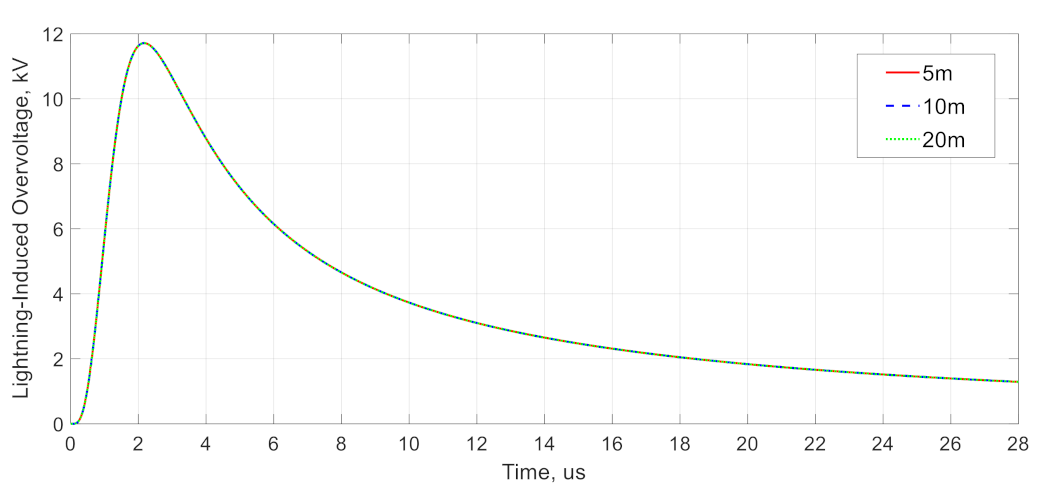
5.3. Effects of Different Cable Lengths
6. Conclusions
Author Contributions
Funding
Institutional Review Board Statement
Informed Consent Statement
Data Availability Statement
Acknowledgments
Conflicts of Interest
References
- Sustainable Energy Development Authority Malaysia (SEDA). Available online: www.seda.gov.my/reportal/re-incentive/ (accessed on 13 November 2020).
- Malaysia Electricity Supply Industry 2.0. Available online: https://www.bakermckenzie.com/en/insight/publications/2019/10/malaysia-electricity-supply-industry (accessed on 15 October 2020).
- Ab Kadir, M.Z.A.; Rafeeu, Y.; Adam, N.M. Prospective scenarios for the full solar energy development in Malaysia. Renew. Sustain. Energy Rev. 2010, 14, 3023–3031. [Google Scholar] [CrossRef]
- Energy Commission. Available online: https://www.st.gov.my/en/contents/publications/energyMalaysia/ (accessed on 20 December 2020).
- Ab Kadir, M.; Misbah, N.R.; Gomes, C.; Jasni, J.; Ahmad, W.W.; Hassan, M. Recent statistics on lightning fatalities in Malaysia. In Proceedings of the International Conference on Lightning Protection (ICLP), Vienna, Austria, 2–7 September 2012; pp. 1–5. [Google Scholar]
- Ab-Kadir, M.Z.A. Lightning severity in Malaysia and some parameters of interest for engineering applications. Therm. Sci. 2016, 20, 437–450. [Google Scholar] [CrossRef]
- Lightning and Surge Protection of SSEG Installations. Available online: https://www.ee.co.za/wp-content/uploads/2018/10/Hano-Oelofse-DEHN-africa-presentation.pdf (accessed on 1 December 2019).
- Zaini, N.; Ab-Kadir, M.; Izadi, M.; Ahmad, N.; Radzi, M.M.; Azis, N.; Wan Hasan, W.Z. On the effect of lightning on a solar photovoltaic system. In Proceedings of the International Conference on Lightning Protection (ICLP), Estoril, Portugal, 25–30 September 2016; pp. 1–4. [Google Scholar]
- Bokoro, P.; Doorsamy, W. Investigation of lightning surge effects on a grid-connected PV plant. In Proceedings of the International Conference on High. Voltage Engineering and Application (ICHVE), Athens, Greece, 10–13 September 2018; pp. 1–4. [Google Scholar]
- Rodrigues, R.B.; Mendes, V.; Catalão, J.P.d.S. Protection of wind energy systems against the indirect effects of lightning. Renew. Energy 2011, 36, 2888–2896. [Google Scholar] [CrossRef]
- Zaini, N.H.; Ab-Kadir, M.Z.A.; Radzi, M.A.M.; Izadi, M.; Azis, N.; Ahmad, N.; Nasir, M.S.M. Lightning surge analysis on a large scale grid-connected solar photovoltaic system. Energies 2017, 10, 2149. [Google Scholar] [CrossRef] [Green Version]
- Elbaset, A.A.; Abdelwahab, S.A.M.; Ibrahim, H.A.; Eid, M.A.E. Performance Analysis of Photovoltaic Systems with Energy Storage Systems; Springer: Suez, Egypt, 2019; pp. 5–9. [Google Scholar]
- Mohanty, P.; Muneer, T.; Kolhe, M. Solar Photovoltaic System Applications—A Guidebook for Off-Grid Electrification; Springer: Cham, Switzerland, 2016. [Google Scholar]
- Saha, K. Planning and Installing Photovoltaic Systems: A Guide for Installers, Architects and Engineers; Routledge: London, UK, 2014; pp. 1–8. [Google Scholar]
- Akbari, H.; Browne, M.C.; Ortega, A.; Huang, M.J.; Hewitt, N.J.; Norton, B.; McCormack, S.J. Efficient energy storage technologies for photovoltaic systems. Sol. Energy 2018, 192, 144–168. [Google Scholar] [CrossRef]
- MS IEC 61215. Crystalline Silicon Terrestrial Photovoltaic (PV) Modules—Design Qualification and Type Approval; IEC: Geneva, Switzerland, 2005. [Google Scholar]
- Teodorescu, R.; Liserre, M.; Rodriguez, P. Grid converters for photovoltaic and wind power systems; John Wiley & Sons: London, UK, 2011; p. 31. [Google Scholar]
- IEEE 2030. 2.1-2019. IEEE Guide for Design, Operation, and Maintenance of Battery Energy Storage Systems, both Stationary and Mobile, and Applications Integrated with Electric Power Systems; IEEE: New York, NY, USA, 2019.
- Ter-Gazarian, A.G. Energy Storage for Power System, IET Power and Energy Series; IET: London, UK, 2011; pp. 32–34. [Google Scholar]
- Sangpanich, U. A novel method of decentralized battery energy management for stand-alone PV-battery systems. In Proceedings of the Asia-Pacific Power and Energy Engineering Conference (APPEEC), Hong Kong, China, 7–10 December 2014; pp. 1–5. [Google Scholar]
- Nimat, S.; Anitha Sarah, S.; Stephen, B.B. Renewable Energy Based Grid Connected Battery Projects around the World—An Overview. J. Energy Power Eng. 2019, 13, 1–23. [Google Scholar]
- Sabiha, N.A. Lightning-Induced Overvoltages In Medium Voltage Distribution Systems. Doctoral Dissertation, Aalto University, Espoo, Finland, 18 March 2010. [Google Scholar]
- Cooray, V.; Fernando, M. Lightning Protection; IET: London, UK, 2010; pp. 15–16. [Google Scholar]
- Izadi, M.; Ab Kadir, M.Z.A.; Hajikhani, M. On the lightning induced voltage along overhead power distribution line. J. Electr. Eng. Technol. 2014, 9, 1694–1703. [Google Scholar] [CrossRef] [Green Version]
- Kannu, P.D.; Thomas, M.J. Influence of Lightning Strike Location on The Induced Voltage on a Nearby Overhead Line. In Proceedings of the Conference on National Power Systems, Kharagpur, India, 27–29 December 2002; pp. 1–6. [Google Scholar]
- African-Market-Outlook-for Solar IPP and C&I Projects 2020–2024. Available online: www.solarpowersummit.org (accessed on 2 October 2020).
- Bortolini, M.; Gamberi, M.; Graziani, A. Technical and economic design of photovoltaic and battery energy storage system. Energy Convers. Manag. 2014, 86, 81–92. [Google Scholar] [CrossRef]
- Sawin, J. Renewable Energy Policy Network for the 21st Century: Renewables 2012 Global Status Report; REN21 Secretariat: Paris, France, 2011. [Google Scholar]
- Malaysia Energy Information Hub (MEIH). Available online: https://meih.st.gov.my/ (accessed on 20 December 2020).
- Liu, J.; Chen, X.; Cao, S.; Yang, H. Overview on hybrid solar photovoltaic-electrical energy storage technologies for power supply to buildings. Energy Convers. Manag. 2019, 187, 103–121. [Google Scholar] [CrossRef]
- Olabi, A.; Abdelkareem, M. Energy Storage Systems Towards 2050. Energy 2020, 219, 119634. [Google Scholar] [CrossRef]
- Solar and Storage for European Homes. Available online: www.solarpowersummit.org (accessed on 2 October 2020).
- Ahmad, N.; Ab-Kadir, M.; Izadi, M.; Zaini, N.; Radzi, M.M.; Azis, N.; Wan Hasan, W.Z. On the performance of a polycrystalline PV panel under different impulse voltages and temperatures. In Proceedings of the International Conference on Lightning Protection (ICLP), Estoril, Portugal, 25–30 September 2016; pp. 1–6. [Google Scholar]
- Jiang, T.; Grzybowski, S. Electrical degradation of Photovoltaic modules caused by lightning induced voltage. In Proceedings of the Electrical Insulation Conference (EIC), Philadelphia, PA, USA, 8–11 June 2014; pp. 107–110. [Google Scholar]
- Jiang, T.; Grzybowski, S. Impact of lightning impulse voltage on polycrystalline silicon photovoltaic modules. In Proceedings of the International Symposium on Lightning Protection (XII SIPDA), Belo Horizonte, Brazil, 7–11 October 2013; pp. 287–290. [Google Scholar]
- Jiang, T.; Grzybowski, S. Influence of lightning impulse voltages on power output characteristics of Photovoltaic modules. In Proceedings of the International Conference on High. Voltage Engineering and Application (ICHVE), Poznan, Poland, 8–11 September 2014; pp. 1–4. [Google Scholar]
- Sekioka, S. An experimental study of sparkover between a rod and a photovoltaic panel. In Proceedings of the International Conference on Lightning Protection (ICLP), Vienna, Austria, 2–7 September 2012; pp. 1–5. [Google Scholar]
- Hossain, M.A.; Ahmed, M.R. Analysis of indirect lightning phenomena on solar power system. Int. J. Electr. Eng. 2014, 21, 127–133. [Google Scholar]
- Köntges, M.; Kurtz, S.; Packard, C.; Jahn, U.; Berger, K.A.; Kato, K.; Van Iseghem, M. Review of Failures of Photovoltaic Modules IEA PVPS Task 13 External Final Report March 2014; International Energy Agency Photovoltaic Power Systems Programme (IEA PVPS): Paris, France, 2014. [Google Scholar]
- Karim, M.R.; Ahmed, M.R. Analysis of Electromagnetic Induction due to Lightning on a Large-Scale Solar Power Generation. In Proceedings of the International Conference on Electrical, Computer and Communication Engineering (ECCE), Cox’sBazar, Bangladesh, Bangladesh, 7–9 February 2019; pp. 1–5. [Google Scholar]
- Zaini, N.H.; Ab-Kadir, M.Z.A.; Radzi, M.A.M.; Izadi, M.; Azis, N.; Ahmad, N.; Nasir, M.S.M. Lightning Surge on the DC and AC Side of Solar PV System. In Proceedings of the Asia-Pacific International Conference on Lightning (APL), Hong Kong, China, 12–14 June 2019; pp. 1–5. [Google Scholar]
- Zaini, N.H.; Ab-Kadir, M.Z.A.; Radzi, M.A.M.; Izadi, M.; Azis, N.; Ahmad, N.; Nasir, M.S.M. On the Effect of Surge Protection Devices (SPDs) Placement for Grid-connected Solar PV Farm. In Proceedings of the International Conference on Lightning Protection (ICLP), Rzeszow, Poland, 2–7 September 2018; pp. 1–5. [Google Scholar]
- Mohammed, Z.; Hizam, H.; Gomes, C. Lightning Strike Impacts on Hybrid Photovoltaic-Wind Systems. Indones. J. Electr. Eng. Comput. Sci. 2017, 8, 115–121. [Google Scholar] [CrossRef]
- Christodoulou, C.A.; Ekonomou, L.; Gonos, I.F.; Papanikolaou, N.P. Lightning protection of PV systems. Energy Syst. 2016, 7, 469–482. [Google Scholar] [CrossRef]
- Christodoulou, C.; Kontargyri, V.; Damianaki, K.; Kyritsis, A.; Gonos, I.; Papanikolaou, N. Lightning performance study for photovoltaic systems. In Proceedings of the International Symposium on High. Voltage Engineering, Pilsen, Czech Republic, 23–28 August 2015; pp. 1–5. [Google Scholar]
- Patil, M.N.P.; Shinde, N. Design and Evaluation of Earthing and Lightning Arrester for Grid Connected Solar Prototype System. Int. J. Eng. Technol. Manag.(IJETM) 2015, 2, 53–57. [Google Scholar]
- Hernandez, Y.M.; Ioannidis, D.; Ferlas, G.; Tsovilis, E.G.T.; Politis, Z.; Samaras, K. An experimental approach of the transient effects of lightning currents on the overvoltage protection system in MW-class photovoltaic plants. In Proceedings of the International Conference on Lightning Protection (ICLP), Shanghai, China, 11–18 October 2014; pp. 1972–1977. [Google Scholar]
- Charalambous, C.A.; Kokkinos, N.; Christofides, N.; Ab Kadir, M.Z.A.; Gomes, C. A simulation tool to assess the lightning induced over-voltages on dc cables of photovoltaic installations. In Proceedings of the International Conference on Lightning Protection (ICLP), Shanghai, China, 11–18 October 2014; pp. 1571–1576. [Google Scholar]
- Belik, M. PV panels under lightning conditions. In Proceedings of the International Scientific Conference on Electric Power Engineering (EPE), Brno, Czech Republic, 12–14 May 2014; pp. 367–370. [Google Scholar]
- Tu, Y.; Zhang, C.; Hu, J.; Wang, S.; Sun, W.; Li, H. Research on lightning overvoltages of solar arrays in a rooftop photovoltaic power system. Electr. Power Syst. Res. 2013, 94, 10–15. [Google Scholar] [CrossRef]
- Ittarat, S.; Hiranvarodom, S.; Plangklang, B. A computer program for evaluating the risk of lightning impact and for designing the installation of lightning rod protection for photovoltaic system. Energy Procedia 2013, 34, 318–325. [Google Scholar] [CrossRef] [Green Version]
- Rahim, N.H.A.; Baharudin, Z.A.; Othman, M.N. Investigation of Wave Propagation to PV-Solar Panel Due to Induced Overvoltage Generated by Lightning Impulse Generator. Adv. Sci. Technol. Lett. (Energy) 2013, 38, 15–22. [Google Scholar]
- Pons, E.; Tommasini, R. Lightning protection of PV systems. In Proceedings of the International Youth Conference on Energy (IYCE), Sio¿fok, Hungary, 6–8 June 2013; pp. 1–5. [Google Scholar]
- Benesova, Z.; Haller, R.; Birkl, J.; Zahlmann, P. Overvoltages in photovoltaic systems induced by lightning strikes. In Proceedings of the International Conference on Lightning Protection (ICLP), Vienna, Austria, 2–7 September 2012; pp. 1–6. [Google Scholar]
- Kokkinos, N.; Christofides, N.; Charalambous, C. Lightning protection practice for large-extended photovoltaic installations. International Conference on Lightning Protection (ICLP), Vienna, Austria, 2–7 September 2012; pp. 1–5. [Google Scholar]
- BS EN 62305–1. Protection against lightning—Part 1: General Principles; BSI: London, UK, 2011. [Google Scholar]
- MS IEC 61000-4-5. Electromagnetic Compatibility (EMC)—Testing and Measurement Techniques—Surge Immunity Test; MS: Selangor, Malaysia, 2007. [Google Scholar]
- The ABC’s of Lightning. Available online: http://www.dehn-usa.com (accessed on 22 March 2021).
- Zaini, N.H. Lightning Performance Analysis of a Grid-Connected Solar Photovoltaic System. Ph.D. Thesis, Universiti Putra Malaysia, Selangor, Malaysia, January 2019. [Google Scholar]
- Rakov, V.A.; Borghetti, A.; Bouquegneau, C.; Chisholm, W.A.; Cooray, V.; Cummins, K. CIGRE Lightning Parameters for Engineering Applications; CIGRE Working Group C4.407; CIGRE: Paris, France, 2013; pp. 1–118. [Google Scholar]
- Nucci, C.A.; Rachidi, F. Lightning-Induced Voltages. In Proceedings of the IEEE Conference Panel Session—Distribution Lightning Protection, New Orleans, LA, USA, 14 April 1999. [Google Scholar]
- Andreotti, A.; Assante, D.; Mottola, F.; Verolino, L. An exact closed-form solution for lightning-induced overvoltages calculations. IEEE Trans. Power Deliv. 2009, 24, 1328–1343. [Google Scholar] [CrossRef]
- Djalel, D.; Ali, H.; Fayçal, C. The Return-Stroke of Lightning Current, Source of Electromagnetic Fields (Study, Analysis and Modelling). Am. J. Appl. Sci. 2007, 4, 42–48. [Google Scholar] [CrossRef] [Green Version]
- IEEE 1410-2004. IEEE Guide for Improving the Lightning Performance of Electric Power Overhead Distribution Lines; IEEE: New York, NY, USA, 2010. [Google Scholar]
- GE Power, “Energy Storage Units,” GEA-33123-(E) Datasheet. Available online: https://www.ge.com/renewableenergy/sites/default/files/related_documents/Reservoir%20Solutions%20Product%20Specification%20Sheets.pdf (accessed on 6 August 2018).
- Cooray, V.; Montano, R.; Rakov, V. A model to represent negative and positive lightning first strokes with connecting leaders. J. Electrost. 2004, 60, 97–109. [Google Scholar] [CrossRef]
- Rakov, V.A. Lightning return stroke speed. J. Lightning Res. 2007, 1, 80–89. [Google Scholar]
- Jankov, V. Estimation of the maximal voltage induced on an overhead line due to the nearby lightning. IEEE Trans. Power Deliv. 1997, 12, 315–324. [Google Scholar] [CrossRef]
- Cooray, G.V. The Lightning Flash; IET: London, UK, 2003; pp. 281–352. [Google Scholar]
- Diendorfer, G. Induced voltage on an overhead line due to nearby lightning. IEEE Trans. Electromagn. Compat. 1990, 32, 292–299. [Google Scholar] [CrossRef]
- MS IEC 60664-1. Insulation Coordination for Equipment Within Low-Voltage Systems—Part 1: Principles, Requirements and Tests; MS: Selangor, Malaysia, 2014. [Google Scholar]
- IEC 60228. Conductors of Insulated Cables; IEC: Geneva, Switzerland, 2004. [Google Scholar]
- Ahmad, A.; Aka-Ngnui, T. Lightning induced voltage on telephone cables and power systems. In Proceedings of the International Conference on Power Systems Transients (IPST’07), Lyon, France, 4–7 June 2007; pp. 1–5. [Google Scholar]


| Items | Description | |
|---|---|---|
| Solar PV modules |
| |
| Combiner box |
| |
| DC and AC cabling |
| |
| Power conditioning equipment | Inverter |
|
| Charge controller |
| |
| Battery Energy storage |
| |
| Circuit breaker |
| |
| Fuse |
| |
| PV Electric meter |
| |
| Connectors, conduit, and brackets |
| |
| Type of BESS | Description | Advantages | Disadvantages |
|---|---|---|---|
| Primary BES |
|
|
|
| Secondary BES |
|
|
|
| Components | Examples of Damage | Description |
|---|---|---|
| Solar PV module/array |     | Defects on the electronic parts, cracking of tempered glass, and arcing at the string ribbon. |
| Inverter |    | Damage to all electronic components and data communication parts. |
| Combiner box |    | Burning and melting due to short circuit events. Breakdown of sensitive components inside the combiner box. |
| Cabling |   | Burning and holes in the insulation of cables. |
| No. | References | Year | Review | Type | Strike Type | External | |||||
|---|---|---|---|---|---|---|---|---|---|---|---|
| Rooftop | Farm | With Battery Energy Storage | Direct | Indirect | Air Termination system | Down Conductor | Earth Termination system | ||||
| 1 | [40] | 2019 | X | X | X | ||||||
| 2 | [41] | X | X | ||||||||
| 3 | [42] | 2018 | X | X | |||||||
| 4 | [43] | 2017 | X | X | |||||||
| 5 | [11] | X | X | ||||||||
| 6 | [11,41] | 2016 | X | X | |||||||
| 7 | [44] | X | |||||||||
| 8 | [45] | 2015 | X | X | X | X | X | ||||
| 9 | [46] | X | X | X | |||||||
| 10 | [38] | 2014 | X | X | |||||||
| 11 | [47] | X | X | X | X | X | |||||
| 12 | [48] | X | X | X | X | X | |||||
| 13 | [49] | X | X | X | X | X | |||||
| 14 | [50] | 2013 | X | X | X | X | X | ||||
| 15 | [51] | X | X | X | X | X | |||||
| 16 | [52] | X | X | ||||||||
| 17 | [53] | X | X | ||||||||
| 18 | [54] | 2012 | X | X | |||||||
| 19 | [55] | X | X | X | X | X | X | ||||
| Components | Solar PV | Battery Energy Storage | Inverter | Transformer | Grid | ||
|---|---|---|---|---|---|---|---|
| Specifications | Power | Voltage | Battery nominal capacity | Nominal AC Power per inverter | Rating | Type | 11 kV |
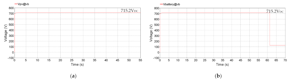
| 1 MW | 715.2 V | 5.26 MWh | 20 kW | 1.5 MVA | Step-up transformer (433 V/11 kV) | ||
| DC Output (VDC) (Solar PV Array and BESS) | AC Output (VAC) (Before Transformer) |
|---|---|
| 715.2 | 354.7 |
| Lightning Waveshape | Rise Time, τ1 (µs) | Fall Time, τ2 (µs) | n |
|---|---|---|---|
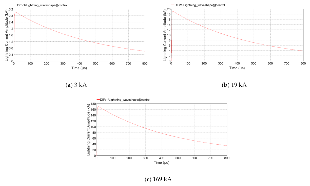
| 10/350 µs | 3 |
| Lightning Current (kA) [56,59,60] | Height (m) [65] | Velocity (m/s) [64,66,67] | The Horizontal Distance between the Lightning Channel and the System, d (m) [68,69,70] | The Point Nearest to the Lightning Strike, x [68,69,70] | Cable Length (m) |
|---|---|---|---|---|---|
| 3 | 2.8 | 1.2 × 10⁻⁸ | 20 | 0 | 5 |
| 19 | 50 | 10 | |||
| 169 | 100 | 20 |
| Lightning Current I0, (kA) | The Point Nearest to the Lightning Strike, x (m) | The Horizontal Distance between the Lightning Channel and the System, d (m) | Lightning-Induced Overvoltage, kV | |||||
|---|---|---|---|---|---|---|---|---|
| Cable Length 5 m | Cable Length 10 m | Cable Length 20 m | ||||||
| VPV/battery | Vinv DC | VPV/battery | Vinv DC | VPV/battery | Vinv DC | |||
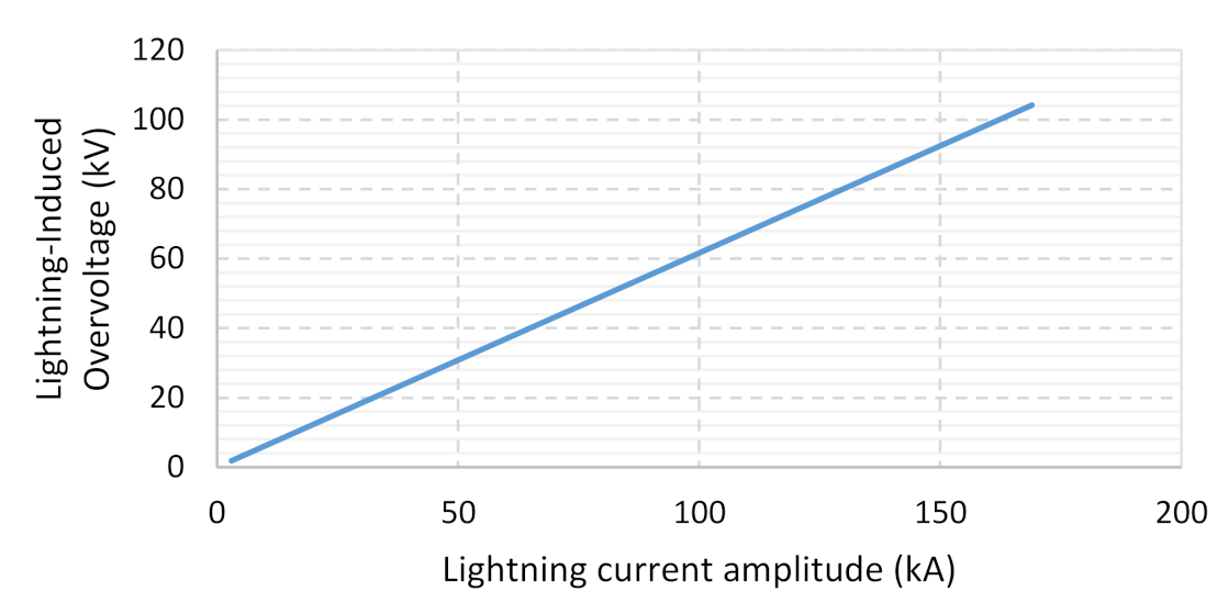
| 3 | 0 | 20 | 1.9 | 1.9 | 1.9 | 1.9 | 1.9 | 1.9 |
| 50 | 1.8 | 1.8 | 1.8 | 1.8 | 1.8 | 1.8 | ||
| 100 | 1.7 | 1.7 | 1.7 | 1.7 | 1.7 | 1.7 | ||
| 19 | 20 | 12.1 | 12.1 | 12.1 | 12.1 | 12.1 | 12.1 | |
| 50 | 11.7 | 11.7 | 11.7 | 11.7 | 11.7 | 11.7 | ||
| 100 | 10.5 | 10.5 | 10.5 | 10.5 | 10.5 | 10.5 | ||
| 169 | 20 | 107.9 | 107.9 | 107.9 | 107.9 | 107.9 | 107.9 | |
| 50 | 104.2 | 104.2 | 104.2 | 104.2 | 104.2 | 104.2 | ||
| 100 | 93.8 | 93.8 | 93.8 | 93.8 | 93.8 | 93.8 | ||
Publisher’s Note: MDPI stays neutral with regard to jurisdictional claims in published maps and institutional affiliations. |
© 2021 by the authors. Licensee MDPI, Basel, Switzerland. This article is an open access article distributed under the terms and conditions of the Creative Commons Attribution (CC BY) license (https://creativecommons.org/licenses/by/4.0/).
Share and Cite
Ahmad, N.I.; Ali, Z.; Ab. Kadir, M.Z.A.; Osman, M.; Zaini, N.H.; Roslan, M.H. Impacts of Lightning-Induced Overvoltage on a Hybrid Solar PV–Battery Energy Storage System. Appl. Sci. 2021, 11, 3633. https://0-doi-org.brum.beds.ac.uk/10.3390/app11083633
Ahmad NI, Ali Z, Ab. Kadir MZA, Osman M, Zaini NH, Roslan MH. Impacts of Lightning-Induced Overvoltage on a Hybrid Solar PV–Battery Energy Storage System. Applied Sciences. 2021; 11(8):3633. https://0-doi-org.brum.beds.ac.uk/10.3390/app11083633
Chicago/Turabian StyleAhmad, Nor Izzati, Zaipatimah Ali, Mohd Zainal Abidin Ab. Kadir, Miszaina Osman, Nur Hazirah Zaini, and Muhammad Hakirin Roslan. 2021. "Impacts of Lightning-Induced Overvoltage on a Hybrid Solar PV–Battery Energy Storage System" Applied Sciences 11, no. 8: 3633. https://0-doi-org.brum.beds.ac.uk/10.3390/app11083633