
Effect of the Depth of Decarburized Layer in SKL15 Tension Clamp on Fatigue Strength


1
Department of Civil and Environmental Engineering, Hannam University, Daejeon 34430, Korea
2
Civil Engineering Planning Team, Incheon International Airport Corporation, Incheon 22382, Korea
3
Korea Railroad Research Institute, Uiwang 16105, Korea
4
Department of Civil and Environmental Engineering, Incheon National University, Incheon 22012, Korea
*
Author to whom correspondence should be addressed.
Appl. Sci. 2021, 11(9), 3841; https://0-doi-org.brum.beds.ac.uk/10.3390/app11093841
Submission received: 2 April 2021
/
Revised: 19 April 2021
/
Accepted: 20 April 2021
/
Published: 23 April 2021
(This article belongs to the Special Issue Advances on Structural Engineering, Volume II)
Abstract
:The surface of a quenched and tempered spring steel may have a decarburized layer from which the carbon component has been reduced. The fatigue strength of the decarburized layer is low compared to the base metal, which can easily develop fatigue cracks. Recently, fatigue failure was reported in the tension clamp (SKL 15) of the DFF-300 rail fastening system during use on one urban transit route in South Korea. As a result of measuring the depth of the decarburized layer of the SKL 15 tension clamp where the fatigue failure occurred, a decarburized layer thinner than the manufacturer’s maximum allowable decarburized layer was found in one of the eight tension clamps. To check the depth of the decarburized layer where the fatigue crack may have initiated, the decarburized layer was assumed to be the initial crack, and fatigue crack initiation was assessed based on the linear elastic fracture mechanics. The manufacturer’s maximum allowable decarburized layer depth of 0.2 mm may result in fatigue cracks.
1. Introduction
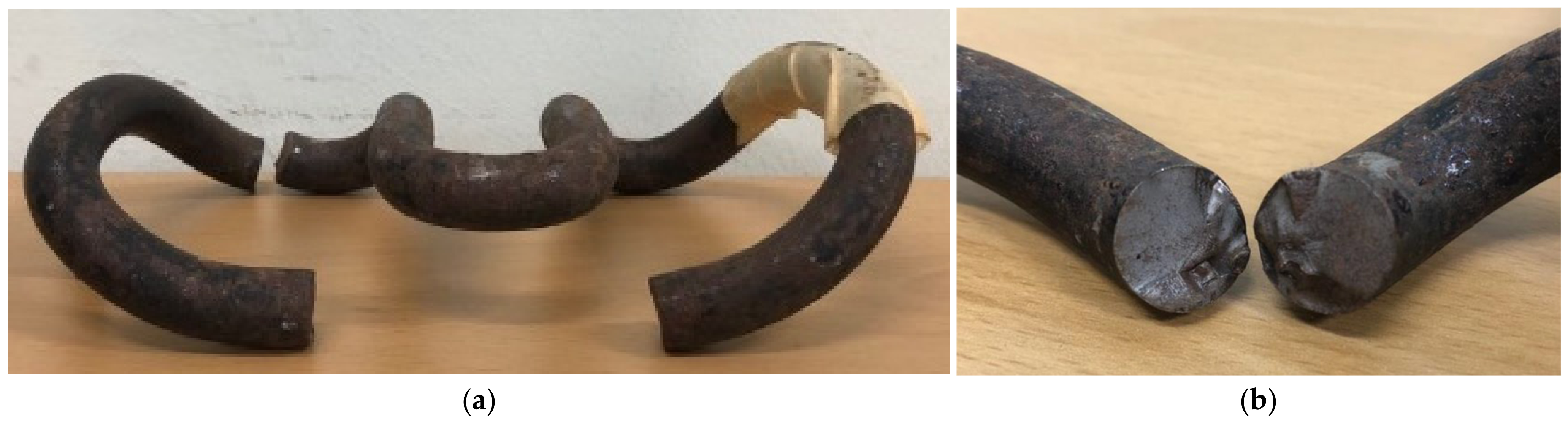
The tension clamp of a rail fastening system is a key element to tie the rail to the sleeper. The design of the tension clamp must prevent fatigue cracks because large numbers of tension clamps are installed in railway tracks and their failure significantly affects the safety of trains. However, the method of fatigue performance evaluation of tension clamps is not standardized; the manufacturer itself conducts a fatigue test and issues a performance report on the fatigue performance. The fatigue failure of tension clamps has been reported in several places. Recently, many SKL15 tension clamps, which are used in the DFF-300 fastening system in South Korea, have been reported to have experienced fatigue failures during service. Figure 1 shows a tension clamp, and its fatigue fracture surfaces, collected at the site of the failures. All tension clamps experienced the failure surface in the same position. The section with the fatigue failure occurred only in the section in which the curve radius was 1200 m or less among the total 12 curve sections in the route. As a result of an in-depth investigation of this fatigue failure, it was confirmed that the depth of the decarburized layer was deeper than that suggested by the manufacturer and excessive stress occurred during train passage [1].
In the case of the tension clamp in the rail fastening system, heat treatment is performed to increase the strength of the metal, which could create the decarburized layer on the surface of the clamp. According to Frost et al. [2], a decarburized layer occurred on the surface of the forged or quenched and tempered steel. This treatment caused decarburization on the surface, producing a soft layer with a lower strength than the base metal; that is, the decarburized layer. Generally, in the case of steel, the endurance limit, which is a stress range that does not cause fatigue cracking, is known to be about 30% to 60% of the tensile strength when a reverse bending load is applied [3]. However, as the carbon component, which is the main factor that determines the strength of steel, decreases, the decarburized layer has very low tensile strength compared to the base metal, so fatigue cracking occurs more easily than in the base metal. Thus, it is expected that the cracks generated in the decarburized layer will play a role in the initial crack, thereby lowering the fatigue strength of the base metal.
The fracture of the tension clamp affects the driving safety of trains, in addition to the deterioration of the serviceability of the track system. Therefore, the early fracture of tension clamps due to the decrease in fatigue strength could result in serious accidents such as train derailments. For this reason, by accurately identifying the effect of the decarburized layer on the decrease in the fatigue strength of the tension clamp, it is possible to prevent the fracture of the tension clamp due to train passage. In this study, for a railway line in South Korea, the depth of the decarburized layer of SKL15, which recently failed due to fatigue, was measured, and the effect of the depth of the decarburized layer on fatigue strength was analyzed using linear elastic fracture mechanics (LEFM). Because the decarburized layer has a lower fatigue strength than the base metal, the depth of the decarburized layer is regarded as the initial crack. By comparing the stress intensity factor range (ΔKI) and fatigue threshold stress intensity factor range (ΔKth), we propose a maximum depth of decarburized layer at which the fatigue crack may not occur in the case of the route under investigation.
2. Investigation of Cause of Fatigue Crack
2.1. Result of Decarburized Layer Measurement
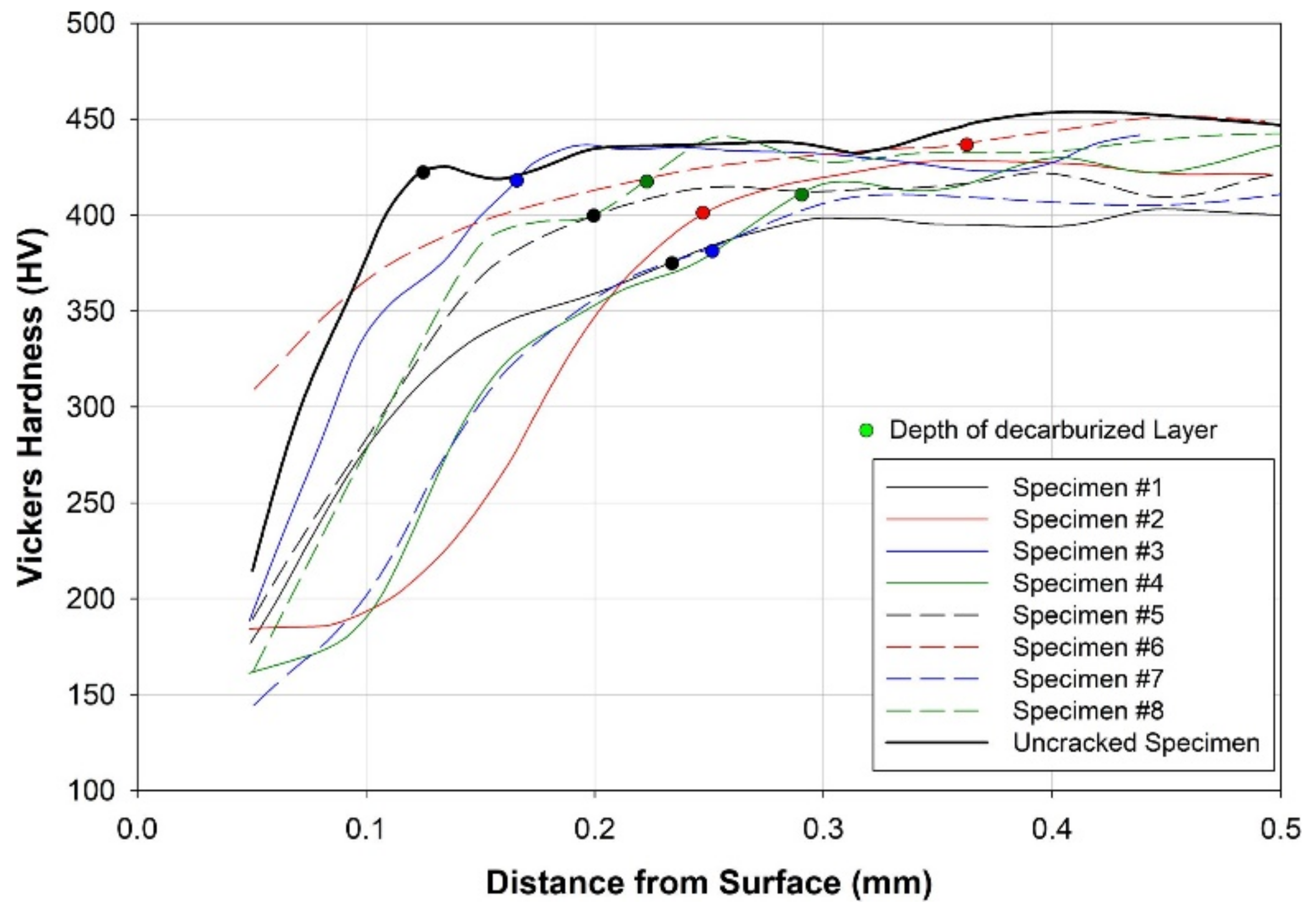
To determine the decrease in the fatigue strength of SKL 15, the depth of the decarburized layer was assessed by measuring the hardness from the cross-section to the depth. The depth of the decarburized layer can be measured by measuring hardness and by evaluating the picture of the tissue of the fracture surface with a microscope. In general, for quenched and tempered steels, the depth of the decarburized layer is determined by measuring the Vickers hardness [4]. The results of measuring the Vickers hardness of fracture surfaces of eight cracked tension clamps and one uncracked tension clamp are shown in Figure 2. The hardness was measured at 30 μm intervals from the surface, and the depth of the decarburized layer was considered to extend to the point at which the hardness was 90% of the difference between the surface and the base, metal as shown in Equation (1), according to Mayott [5].
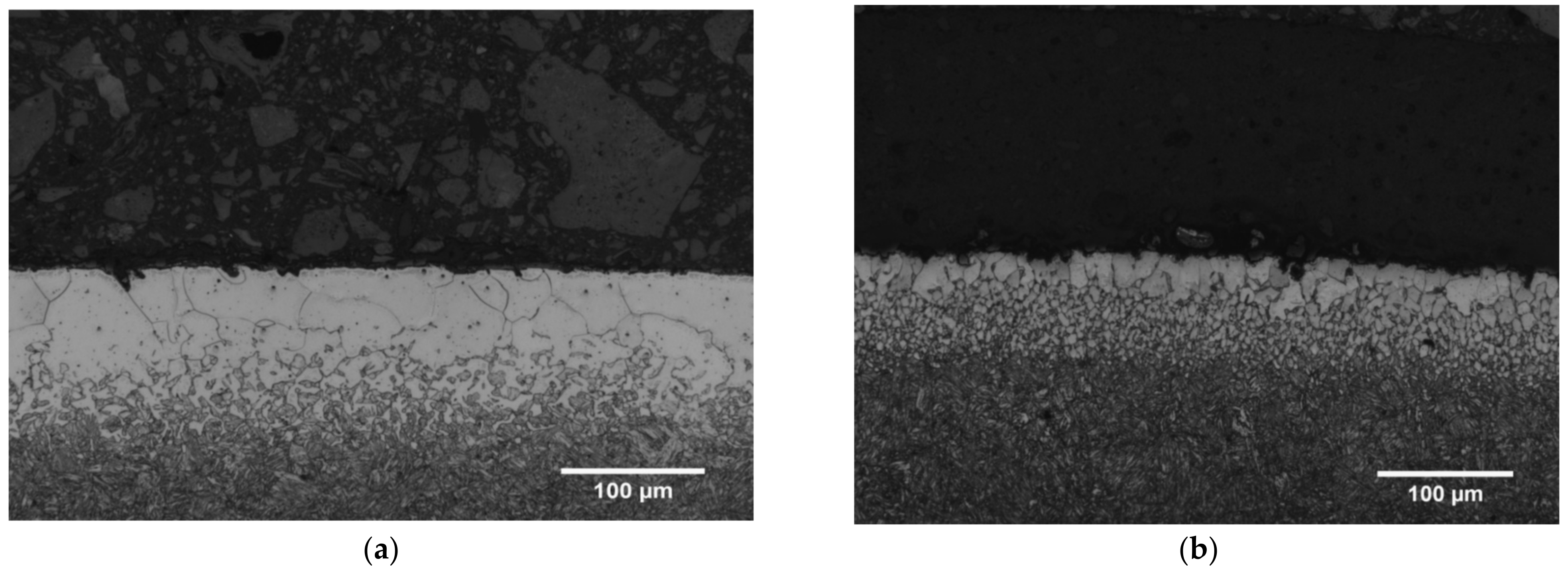
where HVd is the Vickers hardness at the end of the decarburized layer, HVB is the Vickers hardness of the base metal, and HVS is the Vickers hardness at the surface. Thus, the depth of the decarburized layer was determined at the distance from the surface that matched HVd. The depth of the decarburized layer was not constant and showed a significant deviation. The minimum and maximum depths of the cracked specimens were 0.17 and 0.36 mm, respectively. The decarburized layer depth of the uncracked specimen was 0.12 mm. For reference, the maximum decarburized layer depth suggested by the manufacturer is 0.2 mm. With the exception of one of the eight specimens, the depth of the decarburized layer of all specimens was thicker than the manufacturer’s allowable depth. Because the fatigue failure occurred even in the tension clamp with the thinnest decarburized layer, it is necessary to confirm the validity of the manufacturer’s allowable depth. Figure 3 shows pictures taken with a scanning electron microscope (SEM) of the decarburized layers of Specimen #7 and the uncracked specimen. The white layer indicates the area that was completely decarburized. As is clearly shown in the figure, the depth of the white layer of Specimen #7 was much deeper than that of the uncracked specimen.
2.2. Decrease in the Fatigue Strength Due to Decarburized Layer
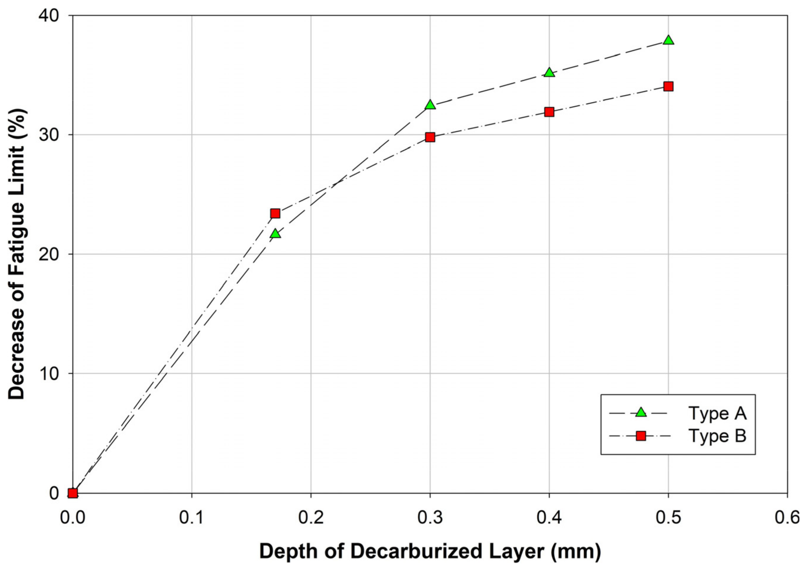
Several researchers have confirmed that the fatigue strength of steel is lowered by the decarburized layer [2,6]. However, opinions on the degree of reduction in the fatigue strength depending on the depth of the decarburized layer differ among researchers. According to Frost et al. [2], when the decarburization layer is present to an effective degree, a constant endurance limit of 325 MPa is seen regardless of the strength of the material. This means that due to the low strength of the decarburized layer, the cracks are generated even under a low stress range in the decarburized layer, and this crack plays a role in the initial crack, which grows into the base metal. Ueda and Ueda [6] determined the change in the fatigue strength according to the depth of the decarburized layer using a fatigue test on plain carbon steel. As the depth of the decarburized layer increases, the fatigue limit of the material decreases (Figure 4). This appears to be because the ΔKI generated at the crack tip increases as the depth of the decarburization layer increases if the size of the initial crack in the decarburization layer is assumed to be the same as the depth of the decarburization layer.
Assuming that the fatigue crack occurs in a much lower stress range than the base metal due to the decrease in the strength of the decarburized layer, in terms of fracture mechanics, the deeper the decarburized layer, the deeper the crack. In the case of a first mode crack, ΔKI generated at the crack tip, as in Equation (2), has a large value as the depth of the crack increases and the range of stress acting on the crack surface increases.
where Sr is the stress range, a is the crack depth, and Fc is the correction factor. The correction factor is determined according to the type of load acting on the crack, the member shape, and the shape of the crack. According to Barsom and Rolfe [7], in order for cracks to grow in cracked steel, the ΔKI generated at the crack tip must exceed the fatigue threshold stress intensity factor range (ΔKth), which is equivalent to Equation (3).
where R is the stress ratio, which is the ratio between the minimum and maximum stress under constant stress amplitude. The fatigue threshold stress intensity factor range (ΔKth) is independent of the depth of the crack and is determined by the stress ratio. Thus, as the decarburized layer thickens, the stress range leading to ΔKth decreases, reducing the fatigue strength. Therefore, the research results of Ueda and Ueda [6], which show the deeper the decarburized layer, the weaker the fatigue strength, can be considered to be valid. However, the degree of fatigue strength reduction according to the depth of the decarburized layer may vary depending on the shape of the member and the type of load; thus, the results of Ueda and Ueda [6] cannot be directly applied to the tension clamp. Therefore, the ΔKth of the tension clamp material, the shape of the member, and the section force acting at the location where the fatigue crack has occurred must be known to determine the fatigue strength of the tension clamp.
2.3. Section Force Generated in the Tension Clamp Due to Train Running
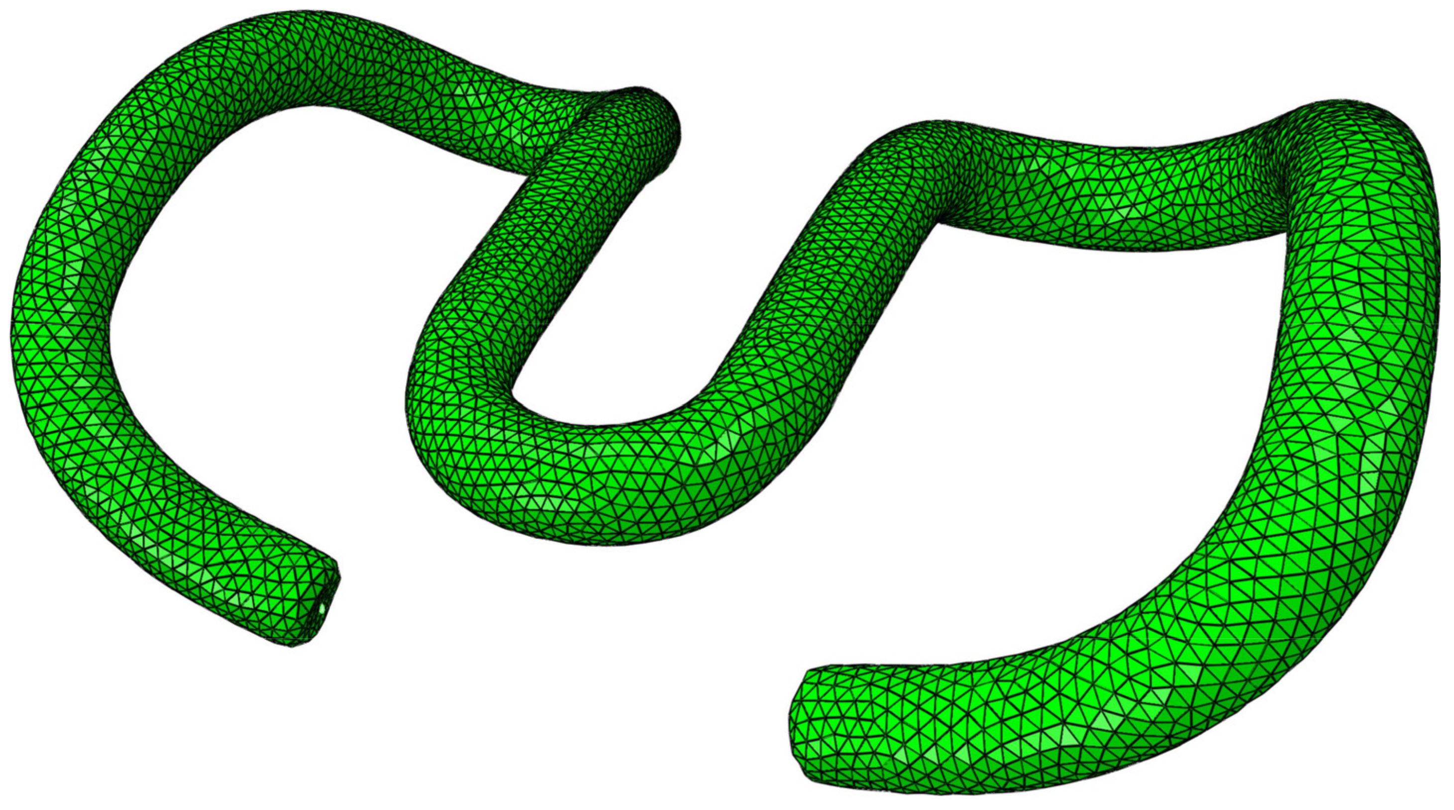
To estimate the section force acting on the fatigue fracture surface, finite element analysis of the tension clamp was performed using ABAQUS [8], a commercial numerical analysis program. To accurately model the shape of the tension clamp, a basic model using a three-dimensional (3D) scanner was composed of a solid element with a tetrahedral mesh. The shape of the model is shown in Figure 5, and the material properties of steel are listed in Table 1.
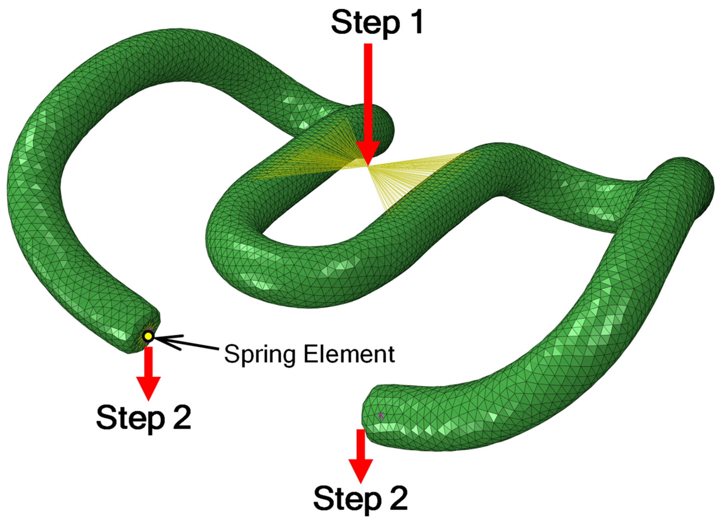
The finite element analysis proceeded in two steps, as shown in Figure 6. The first step was to make the displacement of the end of the middle band reach 9.9 mm to simulate the fastening process by the sleeper screw. This displacement value was measured in an indoor fastening test. In the second step, the spring element inserted into the spring arm was configured to displace 1 mm in the vertical direction to simulate the deflection of the rail caused by the passage of a train. The deflection value of the rail was measured in both straight and curved sections, and it was confirmed that a deflection of about 1 mm occurred regardless of the radius of the curvature of the railway track. During measurement, the speed of the train was approximately 90 km/h. Spring elements were inserted to simulate the elastic pad supporting the tension clamps, and the stiffness of each spring element was 5625 N/mm in the vertical direction.
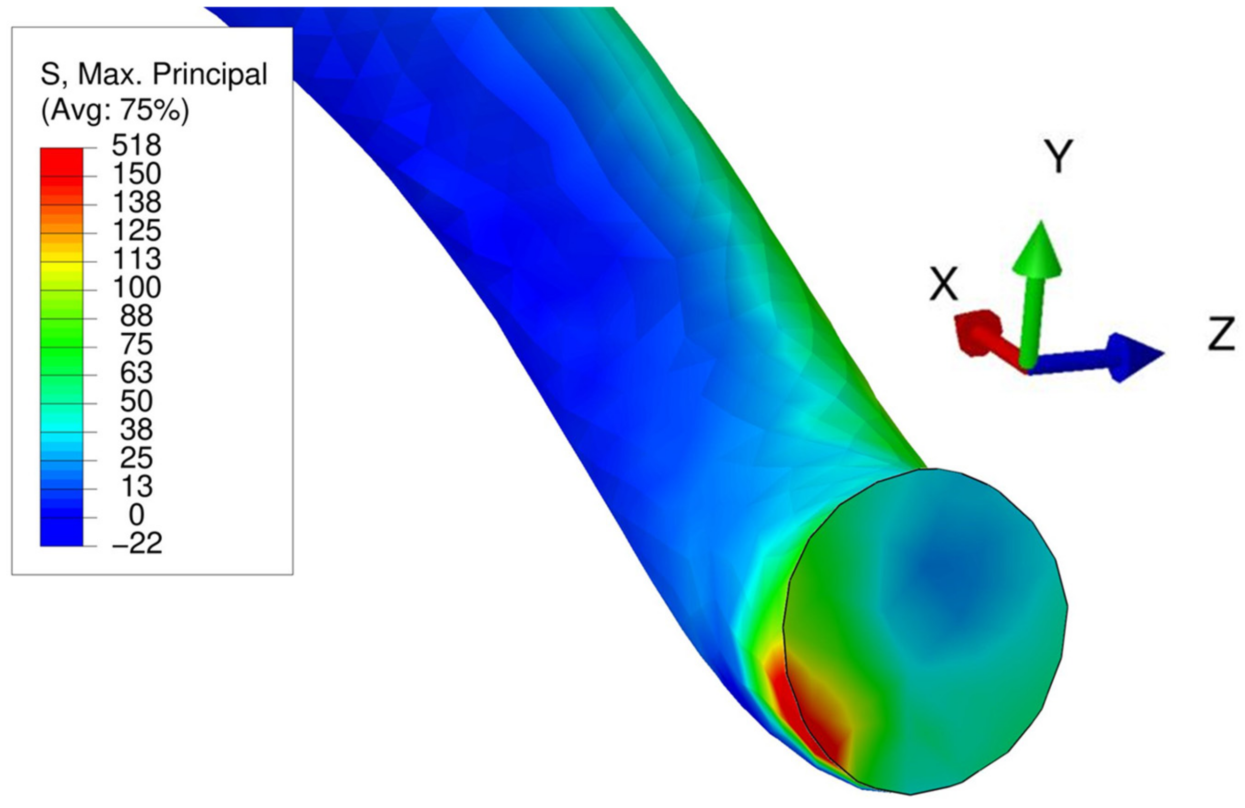
Fatigue cracking is initiated by the stress that occurs repeatedly due to the passage of trains during use. When the decarburization layer is present, the fatigue strength of the decarburization layer is lower than that of the base metal, so the depth of the decarburization layer can be regarded as the initial crack existing in the tension clamp. In this case, when the ΔKI generated in the crack tip is larger than ΔKth, the crack grows in the base metal. Therefore, to calculate ΔKI, it is required to estimate the range of the load generated by train passage in the cross-section where the fatigue crack has occurred. The range of the load generated by the train passage can be estimated by the difference between the section force in Step 2 when the rail deflection occurs due to the passage of the train, and the section force of Step 1 after fastening the sleeper screw. Figure 7 shows the color contour of the range of the maximum principal stress generated by the passage of the train in the cross-section where the fatigue failure occurred. The maximum principal stress was generated in the lower-left end of the cross-section, and the ranges of the section forces and moments associated with the axes shown in Figure 7 are listed in Table 2. The maximum and minimum values, the stress range, and the stress ratio of the main stress fluctuating due to the train passage are listed in Table 3.
3. ΔKI According to the Depth of the Decarburized Layer
Of the section forces acting on the fatigue fracture surface, the tensile force and the moment about the y and z axis affect the opening mode of cracking. Thus, assuming the decarburized layer as the initial crack, ΔKI at the crack tip is defined as ΔKI generated by each force. Because the tension clamp was made of a circular steel bar, the ΔKI equation for tensile force and bending moment was used when there was a crack around the circular steel bar [9].
When the depth of the crack is significantly shallower than the diameter of the round steel bar, ΔKI by tensile force is defined as Equation (4).
where P is the tensile force acting on the cross-section and b is the radius of the steel bar.
ΔKI by bending moment is defined as Equation (5).
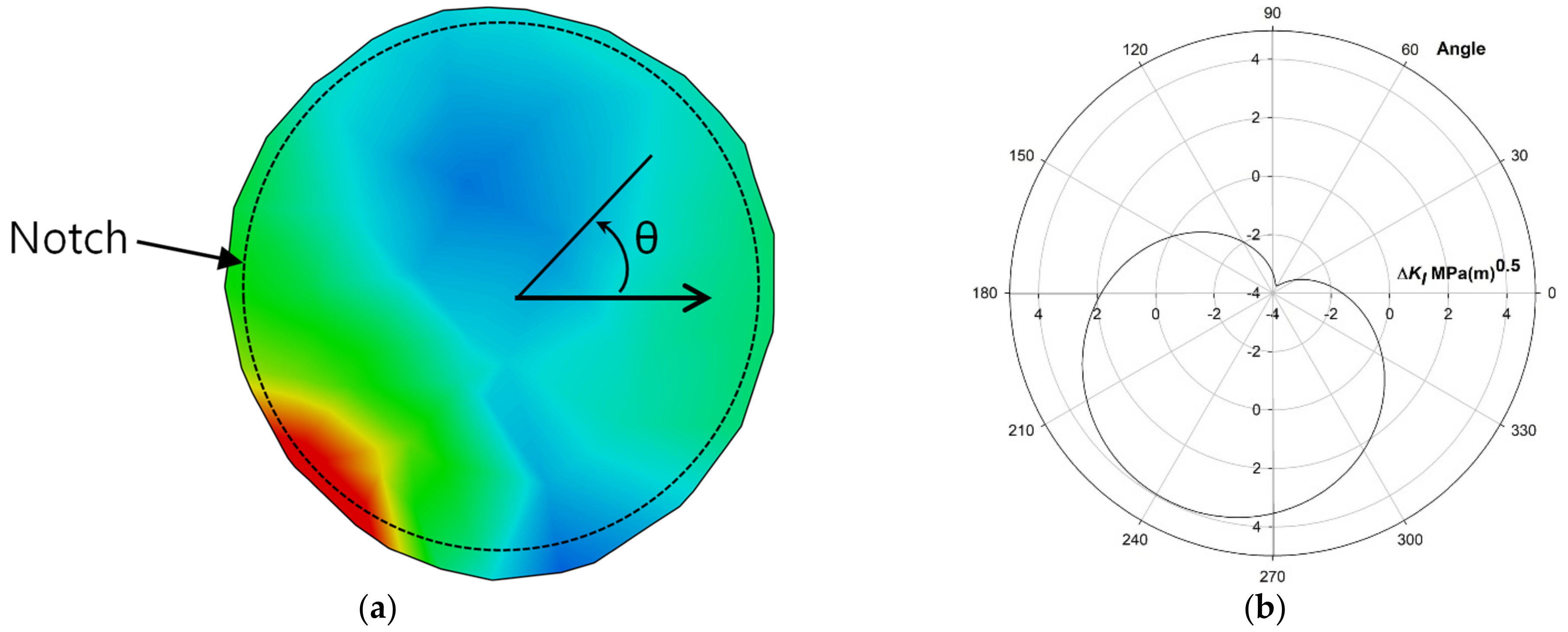
where M is the bending moment acting on the cross-section and θ is the angle from the maximum ΔKI. Under a tensile force, a constant ΔKI occurs in the crack notch around the round steel bar, but under a bending moment, the ΔKI value changes according to the direction of the moment and the position of the notch. A schematic illustration showing the stress range of the fatigue fracture surface and the position of the notch in angles from the y-axis is shown in Figure 8a. The ΔKI value at the notch considering the tensile force and the bending moment in y and z directions is defined as Equation (6).
Substituting the section force calculated in the previous section into Equation (6) and solving for θ, the position and the maximum value at which ΔKI becomes the maximum can be obtained. Figure 8b shows the distribution of ΔKI at the notch when the depth of the decarburized layer is 0.2 mm. The maximum value of ΔKI was 3.96 MPa√m at the position where θ is 243°. Compared with the principal stress distribution in Figure 8a, it can be seen that the maximum stress occurred at the position where θ is 235°, which is consistent with the calculation result of ΔKI.
Prior to determining ΔKth, the critical crack size for short and long cracks should be checked [10]. If the depth of the decarburized layer is too small, the fatigue crack may not be propagated when the applied stress range is smaller than the fatigue limit. Thus, stress range governs the crack initiation. According to Atzori et al. [10], the minimum crack size of the long crack for which the stress intensity factor governs the crack initiation, was defined as Equation (7).
where Δσo is the fatigue limit of unnotched steel. The correction factor Fc is 1.12 in Equation (7). ΔKth for the stress ratio at the crack location obtained in Table 3 was calculated with Equation (3), and its value was 1.74 MPa√m. The fatigue limit of the unnotched steel was determined by the Goodman and Gerber curves [1], which provide the lower and upper bounds of the fatigue limit; these were 78 and 150 MPa, respectively. Considering these factors, the minimum crack size of the long crack was in the range from 0.03 to 0.13 mm. Because the measured depths of the decarburized layer were in the range of 0.17–0.34 mm, the decarburized layer could be considered to be a long crack, and it may be concluded that the stress intensity factor governed the crack initiation.
When the depth of the decarburized layer is 0.2 mm, the maximum depth suggested by the manufacturer, the maximum ΔKI value is 3.96 MPa√m, which is greater than ΔKth. The maximum depth of the decarburized layer at which the fatigue crack may not occur in the same stress state—that is, the depth of the decarburized layer where ΔKth is equal to ΔKI—is 0.04 mm. The depth of 0.04 mm is within the range of the short and long crack boundary, which is between 0.03 and 0.13 mm. Therefore, both stress range and stress intensity factor could govern the fatigue strength. The maximum principal stress range at the cracking location shown in Table 3 was 146 MPa, and was within the range of the fatigue limit of 78 and 150 MPa determined by the Goodman and Gerber curves [1]. According to the measurement of the depth of the decarburized layer of the tension clamp in which the fatigue failure occurred, the thinnest depth was 0.17 mm. The ΔKI value of the depth of 0.17 mm was 3.65 MPa√m and greater than ΔKth of 1.74 MPa√m. Thus, a thick decarburized layer depth could be another reason why the fatigue crack occurred despite the fact that the depth of the decarburized layer was thinner than the maximum depth suggested by the manufacturer (i.e., 0.2 mm).
For these reasons, the maximum depth of the decarburized layer suggested by the manufacturer should be decreased. Developing a thinner decarburized layer requires shorter heat treatment and may result in insufficient stress relief in the material. Therefore, the maximum allowable thickness of the decarburized layer should be determined by comprehensively considering various aspects.
4. Conclusions
The depth of the decarburized layer of the tension clamp in which the fatigue crack occurred was measured, and the depth of the decarburized layer at which a fatigue crack could occur was confirmed via a LEFM-based method. Through this study, the following conclusions were drawn.
- As a result of measuring the depth of the decarburized layer of eight tension clamps with fatigue failure via the hardness measurement method, the distribution of measured depth ranged from 0.17 to 0.36 mm. All but one had a decarburized layer depth greater than 0.2 mm, which is the maximum allowable decarburized layer depth suggested by the manufacturer, and the fatigue failure occurred even in the tension clamp with a decarburized layer depth thinner than the allowable depth.
- Because the fatigue strength of the decarburized layer is lower than that of the base metal, the result of crack growth analysis based on linear elastic fracture mechanics under the assumption that the decarburized layer is an initial crack successfully confirmed whether the fatigue crack occurred according to the depth of the decarburized layer. The stress state at the location of the fatigue crack occurring due to the passage of a train was calculated by finite element analysis, and ΔKth for the stress state at that location was 1.74 MPa√m. In the case of the measured minimum depth of the decarburized layer of 0.17 mm, ΔKI generated by the passage of a train was 3.65 MPa√m. Thus, it was well explained that the fatigue failure occurred despite the fact that the depth of the decarburized layer was thinner than the manufacturer’s allowable depth of the decarburized layer.
- By measuring the depth of the decarburized layer of the tension clamp where the fatigue crack occurred and calculating ΔKI, it was confirmed that it was impossible to prevent the occurrence of fatigue cracking because the depth of the maximum allowable decarburized layer suggested by the manufacturer is too thick. The maximum allowable depth of the decarburized layer of SKL15 on the route on which the survey was conducted should be equal to or less than 0.04 mm. However, the stress range at the crack location was also excessive, so stress range should be controlled.
- The maximum allowable depth of the decarburized layer suggested above is applicable only to the SKL15 tension clamp of the corresponding route and cannot be applied to routes with different operating conditions or to other types of tension clamps or rail clips. However, the approach used in this study could be used to determine the allowable depth of the decarburized layer of other types of tension clamps or rail clips.
Author Contributions
Conceptualization, Y.-C.P.; methodology, Y.-C.P.; validation, H.-B.S.; formal analysis, C.-B.A.; investigation, Y.-C.P., H.-B.S.; resources, M.K.; writing—original draft preparation, Y.-C.P.; writing—review and editing, H.-B.S.; visualization, C.-B.A.; supervision, H.-B.S.; project administration, M.K.; funding acquisition, H.-B.S. All authors have read and agreed to the published version of the manuscript.
Funding
This work was funded by Incheon National University (International Cooperative) Research Grant (2016-2216).
Conflicts of Interest
The authors declare no conflict of interest.
References
- Park, Y.C.; An, C.B.; Sim, H.B.; Kim, M.C.; Hong, J.K. Failure analysis of fatigue cracking in the tension clamp of a rail fastening system. Int. J. Steel Struct. 2019, 19, 1570–1577. [Google Scholar] [CrossRef]
- Frost, N.E.; Marsh, K.J.; Pook, L.P. Metal Fatigue; Dover Publications, Inc.: Meneola, NY, USA, 1974. [Google Scholar]
- Bannantine, J.A.; Comer, J.J.; Handrock, J.L. Fundamentals of Metal Fatigue Analysis; Prentice Hall: Englewood Cliffs, NJ, USA, 1990. [Google Scholar]
- KATS. KS D 0216: Method of Measuring Decarburized Depth for Steel; Korean Agency for Technology and Standards: Sejong-si, Korea, 2001. (In Korean)
- Mayott, S.W. Analysis of the Effects of Reduced Oxygen Atmospheres on the Decarburization Depths of 300M Alloy Steel. Master’s Thesis, Rensselaer Polytechnic Institute, Troy, NY, USA, July 2010. [Google Scholar]
- Ueda, T.; Ueda, S. Effects of surface decarburization on the fatigue properties of plain carbon steel (1st report). J. Jpn. Soc. Test. Mater. 1958, 8, 170–177. (In Japanese) [Google Scholar]
- Barsom, J.M.; Rolfe, S.T. Fracture and Fatigue Control in Structures, 3rd ed.; ASTM International: West Conshohocken, PA, USA, 1999. [Google Scholar]
- Dassault, S. ABAQUS, Version 6.14-1; ABAQUS Inc.: Palo Alto, CA, USA, 2014.
- Tada, H.; Paris, P.C.; Irwin, G.R. The Stress Analysis of Cracks Handbook, 3rd ed.; The American Society of Mechanical Engineering: New York, NY, USA, 2000. [Google Scholar]
- Atzori, B.; Lazzarin, P.; Meneghetti, G. Fracture mechanics and notch sensitivity. Fatigue Fract. Eng. Mater. Struct. 2003, 26, 257–267. [Google Scholar] [CrossRef]
Figure 1.
(a) Fractured tension clamp; (b) fatigue fracture surface.

Figure 2.
Results of measuring the depth of decarburized layers.

Figure 3.
SEM photographs of decarburized layers: (a) Specimen #7; (b) uncracked specimen.

Figure 4.
Decrease in fatigue limit with respect to the depth of decarburization layer (reproduced from Ueda and Ueda, 1958.)
Figure 4.
Decrease in fatigue limit with respect to the depth of decarburization layer (reproduced from Ueda and Ueda, 1958.)

Figure 5.
3D FEA model of SKL15.

Figure 6.
Two-step loading condition.

Figure 7.
Contour of the maximum principal stress at fracture cross-section and directions of axes in Table 2.
Figure 7.
Contour of the maximum principal stress at fracture cross-section and directions of axes in Table 2.

Figure 8.
Results of the case of decarburized layer depth of 0.2 mm: (a) schematic illustration of the notch location; (b) distribution of ΔKI along the notch.
Figure 8.
Results of the case of decarburized layer depth of 0.2 mm: (a) schematic illustration of the notch location; (b) distribution of ΔKI along the notch.


Table 1.
Material properties of tension clamp (38Si7-DIN En 10089).
| Yield Strength | Tensile Strength | Young’s Modulus | Young’s Modulusafter Yielding | Poisson’s Ratio |
|---|---|---|---|---|
| 1150 MPa | 1300 MPa | 200 GPa | 2.02 GPa | 0.3 |
Table 2.
Range of section forces and moments.
| Forces (N) | Moments (N·mm) | |||||
|---|---|---|---|---|---|---|
| Direction | x | y | z | x | y | z |
| Range | 735 | −654 | −134 | −12,700 | 40,400 | 20,500 |
Table 3.
Stress condition at the cracking location.
| Maximum Stress | Minimum Stress | Stress Range | Stress Ratio |
|---|---|---|---|
| 1262 MPa | 1116 MPa | 146 MPa | 0.884 |
Publisher’s Note: MDPI stays neutral with regard to jurisdictional claims in published maps and institutional affiliations. |
© 2021 by the authors. Licensee MDPI, Basel, Switzerland. This article is an open access article distributed under the terms and conditions of the Creative Commons Attribution (CC BY) license (https://creativecommons.org/licenses/by/4.0/).
Share and Cite
MDPI and ACS Style
Park, Y.-C.; An, C.-B.; Kim, M.; Sim, H.-B. Effect of the Depth of Decarburized Layer in SKL15 Tension Clamp on Fatigue Strength. Appl. Sci. 2021, 11, 3841. https://0-doi-org.brum.beds.ac.uk/10.3390/app11093841
AMA Style
Park Y-C, An C-B, Kim M, Sim H-B. Effect of the Depth of Decarburized Layer in SKL15 Tension Clamp on Fatigue Strength. Applied Sciences. 2021; 11(9):3841. https://0-doi-org.brum.beds.ac.uk/10.3390/app11093841
Chicago/Turabian StylePark, Yeun-Chul, Chang-Beom An, Mancheol Kim, and Hyoung-Bo Sim. 2021. "Effect of the Depth of Decarburized Layer in SKL15 Tension Clamp on Fatigue Strength" Applied Sciences 11, no. 9: 3841. https://0-doi-org.brum.beds.ac.uk/10.3390/app11093841
Note that from the first issue of 2016, this journal uses article numbers instead of page numbers. See further details here.