Article

A Comparative Study of Turbulence Methods Applied to the Design of a 3D-Printed Scaffold and the Selection of the Appropriate Numerical Scheme to Simulate the Scaffold for Tissue Engineering

by
Miguel Suffo
* and
Cristobal J. López-Marín
Department of Mechanical Engineering and Industrial Design, High Engineering School, Universidad de Cádiz, Campus Río San Pedro s/n, 11510 Puerto Real, Spain
*
Author to whom correspondence should be addressed.
Submission received: 26 September 2021 / Revised: 3 December 2021 / Accepted: 21 December 2021 / Published: 25 December 2021
(This article belongs to the Special Issue New Trends in Design Engineering II)

Abstract

:
Current commercial software tools implement turbulence models on computational fluid dynamics (CFD) techniques and combine them with fluid-structural interaction (FSI) techniques. There are currently a great variety of turbulence methods that are worth investigating through a comparative study in order to delineate their behavior on scaffolds used in tissue engineering and bone regeneration. Additive manufacturing (AM) offers the opportunity to obtain three-dimensional printed scaffolds (3D scaffolds) that are designed respecting morphologies and that are typically used for the fused deposition model (FDM). These are typically made using biocompatible and biodegradable materials, such as polyetherimide (PEI), ULTEM 1010 biocompatible and polylactic acid (PLA). Starting from our own geometric model, simulations were carried out applying a series of turbulence models which have been proposed due to a variety of properties, such as permeability, speed regime, pressures, depressions and stiffness, that in turn are subject to boundary conditions based on a blood torrent. The obtained results revealed that the detached eddy simulation (DES) model shows better performance for the use of 3D scaffolds in its normal operating regime. Finally, although the results do not present relevant differences between the two materials used in the comparison, the prototypes simulated in PEI ULTEM 1010 do not allow their manufacture in FDM for the required pore size. The printed 3D scaffolds of PLA reveal an elastic behavior and a rigidity that are similar to other prototypes of ceramic composition. Prototypes made of PLA reveal unpredictable variability in pore and layer size which are very similar to cell growth itself and difficult to keep constant.

1. Introduction

In tissue engineering (TE) and bone regeneration, a bone tissue scaffold [1] defines an artificially prepared temporary matrix with a three-dimensional structure. The scaffolds must consist of a three-dimensional porous structure with high inter-connectivity while supporting and maintaining the original tissue shape. These provide support and channels for cell seeding, proliferation and differentiation, vascularization, and transportation of nutrients, as well as metabolic waste [2,3]. The mechanical properties of the scaffolds must match the implant site to ensure mechanical stability in the healing process, thus avoiding stress shielding. Similar to implants or prostheses, scaffolds must be biocompatible, biodegradable and osteoinductive [4,5]. The mechanical stimulation of scaffolds in the body includes matrix deformation. The flow of interstitial fluid (ISF) is a relevant method for the mechanical stimulation of scaffolds [6,7]. ISF flows under the action of a mechanical load, muscle contraction, blood pressure, etc. Furthermore, these forces generate fluid shear stress (FSS) and wall shear stress (WSS) [8,9] on the scaffold surface.
Ouyang et al. [10] and Seyed et al. [11] have investigated the influence of pore size on the hydromechanical properties of porous scaffolds, as well as the correlation with cell response and bone regeneration. They describe a scaffold with pores the size of 650 μm making use of titanium material. Xingzhi Liu [12] have used the same pore size; however, they utilized a poly(l-lactic acid) electrospun microfibrous structure. Zamani et al. [13] have studied the distribution of FSS in scaffolds with different pore sizes: 300, 600, and 900 μm. To generate the desired level of mechanical stimulation in FSS, Zhao et al. [14] have combined the CFD and the finite element (FE) methods to quantitatively evaluate the influence of scaffold geometry (structure, pore size, and porosity) on FSS. Despite the fact that there is only one type of ceramic material printed stereolithography (SLA) used, Mirkhalaf et al. [15] highlight the importance of the architecture of the scaffold and the relevance of the geometric parameters in its selection. However, none of these works show any use of CFD calculation methods or turbulence models.
Mendoza et al. [16] state that the k-ε model is the most often used model in fluid dynamics for the calculation of turbulent flows. Its standard version is only based on two transport equations for the estimation of turbulence: the eddy kinetic energy (k) and the eddy energy dissipation rate (ε), assuming a total turbulent flow. The k-ω standard or Wilcox model is based on the equations of k and the specific dissipation rate (ω). The k-ω SST (shear stress transport) model, developed by Ansys Fluent, improves the formulation in such a way as to take advantage of the robustness and efficiency of the k-ω model in the inner zones of the boundary layer. The precision of the k-ε model in the outer zones decreases the weakness of the Wilcox model given the presence of the higher Reynolds values. The model also improves the calculation of the FSS derived from turbulence, as well as the computation of the pressure gradients [17].
Tiftikçi et al. [18] and Wei et al. [19] conclude that the Reynolds average Navier–Stokes (RANS) models, using the Boussinesq eddy viscosity hypothesis, fail to take into account an isotropic eddy viscosity, as it does not fully reflect reality. Thus, they are not suitable to calculate turbulence or anisotropic flows. In order to solve this limitation, the application of the Reynolds stress model (RSM) is necessary. Instead of assuming the eddy hypothesis, this model resolves the transport equations for each term of the Reynolds stress tensor. In many cases, the RANS models based on the Boussinesq hypothesis provide good results. Thereby, the computational power and time of the RSM model are justified under the presence of a high number of eddies or secondary flows. These authors also indicate that the large eddy simulation (LES) model, which belongs to the filtered-type models, calculates eddies directly in an unsteady simulation. Neither of them makes assumptions on the eddies with a size lower than the mesh element size; these are simply neglected, thus decreasing the computing time. The LES models are not suitable for very complex geometries. Nevertheless, in the case of eddy flows, the LES models approach experimental values in a better way than the RANS-type models.
The direct numerical simulation (DNS) calculation method simulates the whole turbulence range from the Kolmogorov smallest microscale to the integral scale, avoiding the application of eddy models. The main limitation of this method is that it requires some previous meshing calculations that depend on the Reynolds number. In the case of water, the number of meshing processes is of the order of 10¹¹, which is impossible to address with the actual processing technology. Therefore, different models must be used for the calculations of eddies. For the Reynolds stress calculation, the Reynolds stress tensor or the Boussinesq eddy viscosity hypothesis can be used, given that these relate to the Reynolds stress with the velocity gradients. If the latter is applied, then different calculation methods can be considered to obtain the eddy viscosity, such as the Spalart–Allmaras method, the k-ε and the k-ω methods or any of their variations. In the case of the Spalart–Allmaras method, a single additional equation is used, whereas the k-ε and k-ω methods include two additional equations. On the contrary, the very large eddy simulation (VLES) models filter a large amount of the eddies, as they apply the k-ε or k-ω methods to subsequently apply a filter. The scale adaptive simulation (SAS) model is the improved version of the unsteady RANS models, as it is based on the Rotta scalar length equation reformulation, representing a combination of the Rotta and the k-kl (k-kl- ω transient) models. This model’s performance is similar to detached eddy simulation (DES) models, overcoming the RANS and LES models for poor meshes. Lastly, the DES model was formulated in order to solve the caveats of the LES methods, particularly for bounded flows at high Reynolds numbers, where the LES simulation takes a very high computing power. The DES model is a LES-RANS hybrid, as it is based on a LES model. However, the boundary layer and surroundings were simulated with RANS models, such as the Spalart–Allmaras, the realizable k-ε and the SST k-ω, that were modified for unsteady systems.
The diagram shown in Figure 1 depicts a classification of the main CFD calculation methods currently used and previously commented.
AM, as well as 3D printing (3DP) [20], allow the manufacture of any type of complex geometry whose processes imply the addition of layers upon layers of material until obtaining the part or the prototype pre-designed in 3D using a CAD software tool [21]. Some authors have called these techniques computer-aided tissue engineering (CATE) [22] and other designed applications, based on the same concept [23,24]. According to [25,26], among these additive technologies, FDM is one of the most widely used methods due to its simplicity, versatility, low cost and the large number of materials that it is able to carry [27]. Within FDM, the properties of the materials are highly influenced by the processing parameters (3D printers) [28]. For these reasons, it is necessary to test this manufacturing technology with some biocompatible materials capable of reproducing geometric architectures required by 3D scaffolds.
In this work, a comparative analysis is carried out to find the most adequate turbulence method for the design of a 3D scaffold by FDM 3D printing techniques [12,29]. For this, two biocompatible materials of similar densities were selected which are commonly used in FDM additive manufacturing type (polyetherimide “PEI”, ULTEM 1010 biocompatible and polylactic acid “PLA” materials); a geometry was also selected based on the FDM’s own layer-by-layer extrusion. Furthermore, PLA possesses properties that include biocompatibility and degradability, and it is the main polymer which is used as a precursor in the FDM technique [30]. In regard to Suffo [31] and Suffo et al. [32], the commercial PEI-ULTEM 1010 material was subjected to tests that were meant to solve the adhesion problems in dental prostheses. Additionally, this material has had the best result in a recent cytotoxicity test (ratio live/dead) as can be seen in reference [33], improving on materials such as Ti5, polyether ether ketone (PEEK) and even on PLA itself. Thus, this material is worth trying as a scaffold due to its good biocompatibility and viability properties in cell growth. It is yet unknown whether it is possible to manufacture porous 3D scaffolds with PEI-ULTEM 1010 at small sizes directly from the filament material by applying FDM techniques. A new CAD 3D model is designed and imported to a finite element-CFD software package in order to investigate the fluid properties of the scaffold. Once the best CFD calculation method was selected, the physical and mechanical properties of the 3D scaffolds showed a better performance within its usual work environment. Finally, the two biocompatible materials with three different configurations of pore sizes (300, 400 and 500 μm) were compared with the best combination of macro and micro properties present: porosity (pore and layer size), viscous stresses and pressure drops [13].

2. Materials and Methods

2.1. Fluid-Structural Simulation Test

In order to carry out the selection process of the fluid-structure interaction (FSI) calculation method, a comparative fluid flow analysis was made through the 3D scaffold. The two-way FSI methods (K-ε realizable, K-ω SST, Reynolds stress-ω; SAS and DES K-ω SST) were used to evaluate the fluid equivalent Von Mises stress on a 3D geometric model designed especially for FDM process (see Figure 2a). The models have the following dimensions for 300, 400 and 500 μm pore size: 9 mm × 0.47 mm × 9 mm, 10 mm × 0.47 mm × 10 mm and 11 mm × 0.47 mm × 11 mm (length × width × height) (see Figure 2b). The proposed geometric design tries to avoid cubic geometric matrices that present sharp corners.
Ansys fluent and Ansys mechanical APDL (steady structural) were used to perform the two-way FSI analysis to predict pressures and vacuums, velocity, WSS and FSS. To simulate the effect of the loading conditions, the scaffold was introduced in a prism whose dimensions fit the scaffold (Figure 2c). Physical properties that reproduce the blood-stream regarding density and viscosity were simulated inside the prism (at a density of 1074 Kg/m3, as the blood density is within the range of 1056 and 1088 Kg/m3 and a dynamic viscosity of 3.5 × 10⁻³ Pa·s) [18,19,34]. The mechanic properties of the scaffold material were empirically obtained from the tensile test, which allowed us to establish its elasto-plastic behavior. According to the fluent mesh, a scaffold solid model domain was a tetrahedral mesh. The fluid model domain was composed by hexahedron and tetrahedron meshes composed of elements which were 0.12 mm in size, with the total number of elements being 2,940,976. The structural mesh consisted of 154,143 elements, mainly tetrahedrons. The ASME grid convergence index (GCI) method [35,36] was carried out by varying the size of the elements between the range of values (0.15–0.12 mm) and (0.12–0.07). It was decided to use a criterion of maximum admissible error of 5% in GCI. The range comprised of 0.12–0.07 mm revealed an average approximated error of a 2%, an average extrapolated error in the interval 2.5% < eext < 3% and a GCI in the interval 3% < GCI < 4%, making use of the physical parameters measured in both simulations. In the case of 0.15–0.12 mm, the errors were greater than the maximum admissible. For all simulations, the “Wall y+” parameter was calculated to provide information on the proximity and reliability of the mesh in areas close to the boundary layer [37]. The parameter Wall y+ presents very similar maximum values for both materials included in the internal 5 < y+ < 10. Therefore, the boundary layer is located in the buffer zone, that is, the transition region between the viscosity-dominated region and the turbulence-dominated part of the flow. These values reveal a minimal relative influence of viscosity in the calculation of shear stresses [38]. As indicated before, the geometric model describes one modular structural level that is scalable to more levels. Each level is made up of 2 coils crossed at 90°, attached by a solid covering. For the CFD study, a steady problem based on pressure was proposed, with the gravitational stress being neglected and using the Navier–Stokes’s viscosity equations. According to the control volume, an inlet fluid velocity of 2 m/s was applied to the top surface, whereas a zero-pressure outlet was applied to the bottom surface. A boundary wall condition with no shear stress was assumed for the sides and result convergence was performed applying a residual criterion value of 1×10⁻⁵ [39]. All simulations were carried out on a Dell precision tower 7920 workstation equipped with an Intel Xeon Silver 4216 2.1 GHz (3.2 GHz Turbo, 16 cores, 9.6 GT/s 2UPI, 22 MB Cache), and each complete simulation was performed at one time over approximately 4 h.
Once the results of the CFD analysis were obtained, the pressure distribution on the external surface of the model was exported as additional forces in the static structural analysis, with the aim to prove the stability of the model under stress. The bottom flat surface of the model was fixed by a supporting point.

2.2. SEM

The printed 3D scaffolds were also analyzed by scanning electron microscopy (SEM) techniques to investigate the morphology of the materials at the micro and nano scales and to investigate the distribution of the pore sizes. Images were acquired at (x67–x71) magnification using a Dual Beam FEI Scios 2 microscope.

2.3. Materials

The 3D scaffold used in the simulation tests was made of PEI material [40,41], particularly ULTEM 1010 filament biocompatible, which was supplied by Sabic (Riyadh, Saudi Arabia) and adapted for a Fortus 450 MC machine. A T14 type nozzle (0.33 mm) was used to manufacture it. The same material was used for the support material by means of a T16 type nozzle (0.254 mm) according to [15]. As reported by the manufacturer’s data sheet (see an extract in Table 1), the YZ orientation in the manufacture of the scaffold presents a higher tensile stress value, and thus, such a configuration was used in the machine’s software [33].
Acording to the manufacturer’s data sheet (see an extract in Table 2), the results obtained were compared with the same 3D scaffold, however, using PLA filament biocompatible material supplied by RS Pro and adapted to a Ultimaker 2 Extended+ machine. A layer height of 0.2 mm, wall thickness of 0.7 mm, 15% of infill density, 200 °C of printing and 60 °C of build plate temperatures was used to manufacture it.

2.4. Mechanical Properties

The mechanical properties were characterized by uniaxial compression (Shimadzu AG-I Autograph) with a 5 kN load cell and a speed of 0.05 mm min−1. The tests were carried out on samples obtained by 3D scaffolds printed in PLA. The compressive strength and maximum strain were obtained from the maximum strain before the crush, and the elastic modulus was obtained from the initial slope of the stress-strain curve. For this, specific areas of each 3D-printed scaffold (300; 400; 500 μm) were measured; these are: (89 ± 0.5; 106.7 ± 0.2; 127.9 ± 5.7 mm2). The thicknesses maintained constant values and were equal to 0.45 mm in all areas.

3. Results and Discussion

3.1. Selection of the FSI Calculation Method

Table 3 summarizes the results obtained with 5 different calculation methods applied to a 400 μm 3D scaffold.
Furthermore, plots included in Figure 3 illustrate the comparative results for each property.
Using these results, it was possible to choose the best FSI method that led to the continuation of the study. The K-ε model was rejected, as its outputs showed noticeable discrepancies compared with those obtained with the rest of the models. Similarly, the Reynolds model was discarded based on the outputs observed in the turbulence graphic. Despite the fact that the remaining three models showed minor differences, the DES model was finally selected, as the other two models (K-ω and SAS) provided similar turbulence results. The DES model reached a better performance by considering smaller or lower energy eddies.
For each of the materials used in the comparison, the parallel between the DES calculation in the scaffolds containing different pore sizes (300, 400 and 500 µm) is shown in Figure 4. Despite a higher speed value than reported in previous studies, the used material supported the blood-induced viscous stress in the three configurations of the pores. As the size of the pore increased, the decreasing tendencies in all the physical properties showed significant improvements, resulting in permeability enhancement [17,18,19]. It is interesting to observe that the pressure drops as low as 300 µm for PLA, while PEI turns out to be the highest of all. In all the physical properties studied, PLA shows similar results to PEI, highlighting an improvement in pore size of 400 µm in viscous tension. This reveals that this pore size could be very suitable for this material. PLA shows improvement ratios between pore sizes in all the properties studied.
The Re that were determined taking into account Darcy’s law were between 1000–1200 (300 µm–500 µm, respectively). The results are based on the parameters obtained from maximum velocities inside different pores.
Haley et al., 2021 [34] have evaluated Re for cases of stenosis due to the disparity of the values used in these cases. The values obtained here are significantly higher than those shown in their study.
However, the parameters considered by these authors would not be similar to the case studied in this paper. This trend also indicates that if the size of the pore increases, the flow within becomes more turbulent. Nevertheless, the size of the pore shall be chosen according to biochemical criteria and convenience for cell growth, as the larger the pores, the more difficult it is for the cell to find a stable and inductive specific surface to reproduce. The observation shows the influence of the surface on the scaffold at regular intervals of cell growth and how the size of the pores progressively diminishes.
The results of the CFD-structural analysis allow the PLA material with the 400 µm model to be chosen due to the improvement seen in the mechanical properties, particularly the Von Mises maximum stress caused by the viscous friction as an external load, which is 51%. This is as compared to the value obtained in the 500 µm model, which is equivalent to only 28%. That is because of its larger mass and volume of the internal forces as well of deformations. It is interesting to highlight the very similar behaviour that both materials present in the WSS parameter for 400 µm, while PLA supports less Von Mises stresses. This may be due to the influence of the higher stiffness of this material in the structural static analysis.
Similar trends occur with the turbulence energy in PLA. For all sizes, they are lower than those obtained with PEI material.

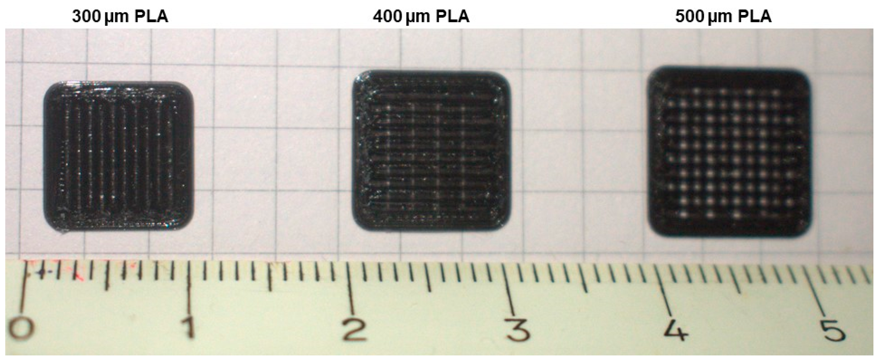
3.2. The Manufacturing of 3D Scaffolds
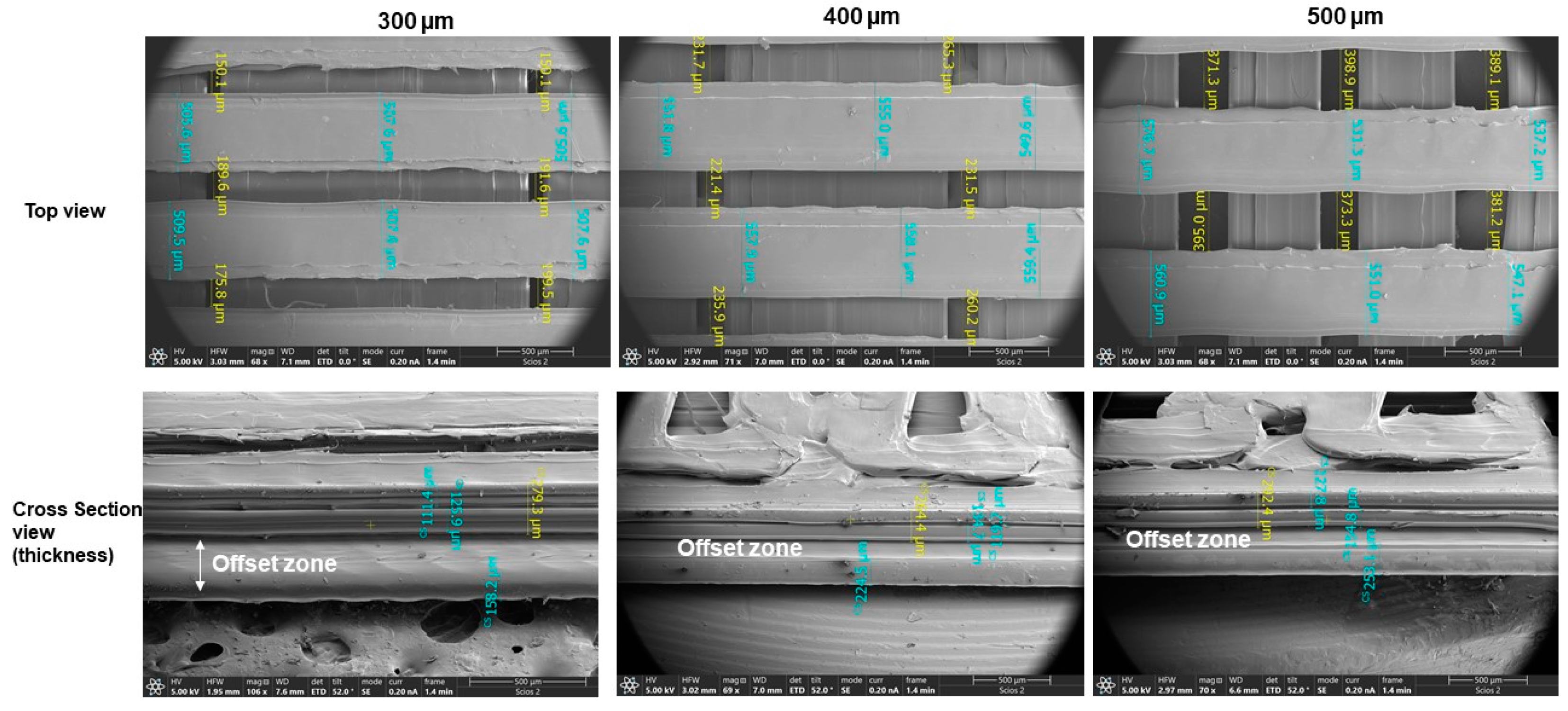
The manufacture of the 3D scaffolds with the PEI-ULTEM material was not feasible given the existing limitations in the extruder nozzle. Each layer of this material in the Fortus 450 MC supposes a thickness of 0.33 mm, which requires a redesign in its geometry so that it can admit this limitation. The melting temperature is too high (close to 300 °C) to be used on another desktop printer, such as the Ultimaker. Although an attempt was made to adapt the 3D scaffold model to the specific requirements of the printer nozzle, no valid results were achieved, and too much time was used stabilizing the printer and material, which reduces the possibility to produce this type of small and porous part using this technology.
However, the manufacture of the 3D scaffold in PLA material was possible in the three pore sizes. Figure 5 shows the printed 3D scaffolds.
Figure 5 illustrates the precision obtained after the manufacturing process. The PEI-ULTEM material sample does not show void architecture due to the unique deposition process of the Fortus 450 MC printer. Reference [42] does obtain a porous structure of 800 µm by means of FDM with a type of PEI material acquired in granules. Subsequently, a prior extrusion filament was obtained. Regardless of the additional cost involved, each process adds uncertainty to the characteristics of the PEI material. However, these cannot be comparable models, since, in the present case, the manufacture is carried out directly from the PEI filament acquired from the Sabic manufacturer and is not manufactured with the same printer. The samples in PLA material present a very regular architecture of pores, without cracks perceptible to the naked eye. As this is the first time that a geometric model using this particular material and characteristics was made, comparisons and discussions with previous studies were not feasible.

3.3. SEM Test

We have performed SEM studies on a 3D scaffold of PLA material to analyze the accuracy of the three pore size settings and the size of the printed layers. Figure 6 displays the highly variable layout and sizes of this type of 3D scaffold made with the FDM technique.
In none of the cases is there a clear trend towards a fixed pore size. However, in the layer width, two superimposed layers are observed that correspond to the passes made by the extruder nozzle in each direction. A total 12 measurements have been carried out in different places; the average pore sizes measured for 300, 400 and 500 µm turned out to be 175.95 ± 19.55 µm, 238.78 ± 19.45 µm y, and 382.82 ± 43.37 µm, respectively. Contractions have been applied to the pores, whose magnitudes were close to 40% in 300 and 400 µm, as well as 23% in 500 µm. Similarly, the average measured layer sizes turned out to be 517.77 ± 25.42 µm, 557.68 ± 13.35 µm, and 549.37 ± 17.45 µm, respectively. The cross-section view shows an offset zone between the lower part of the 3D scaffolds and the first layer deposited, whose measurements are: 223.4 ± 7.93 µm, 247.83 ± 1.15 µm and. 238.47 ± 9.26 µm. This offset may be due to a lower contraction of the material in that lower area attached to the tray, in which the temperature gradient is not that high. Similarly, the thicknesses of each of them have been measured, applying the correction of the corresponding angle until obtaining its true magnitude, resulting in: 460.40 ± 16.19 µm, 460.40 ± 16.19 µm, 488.9 ± 22.04 µm and, 545.50 ± 9.1 µm. This last result suggests an increase in thickness as the pore size increases and, therefore, the size of the 3D scaffold increases as well.

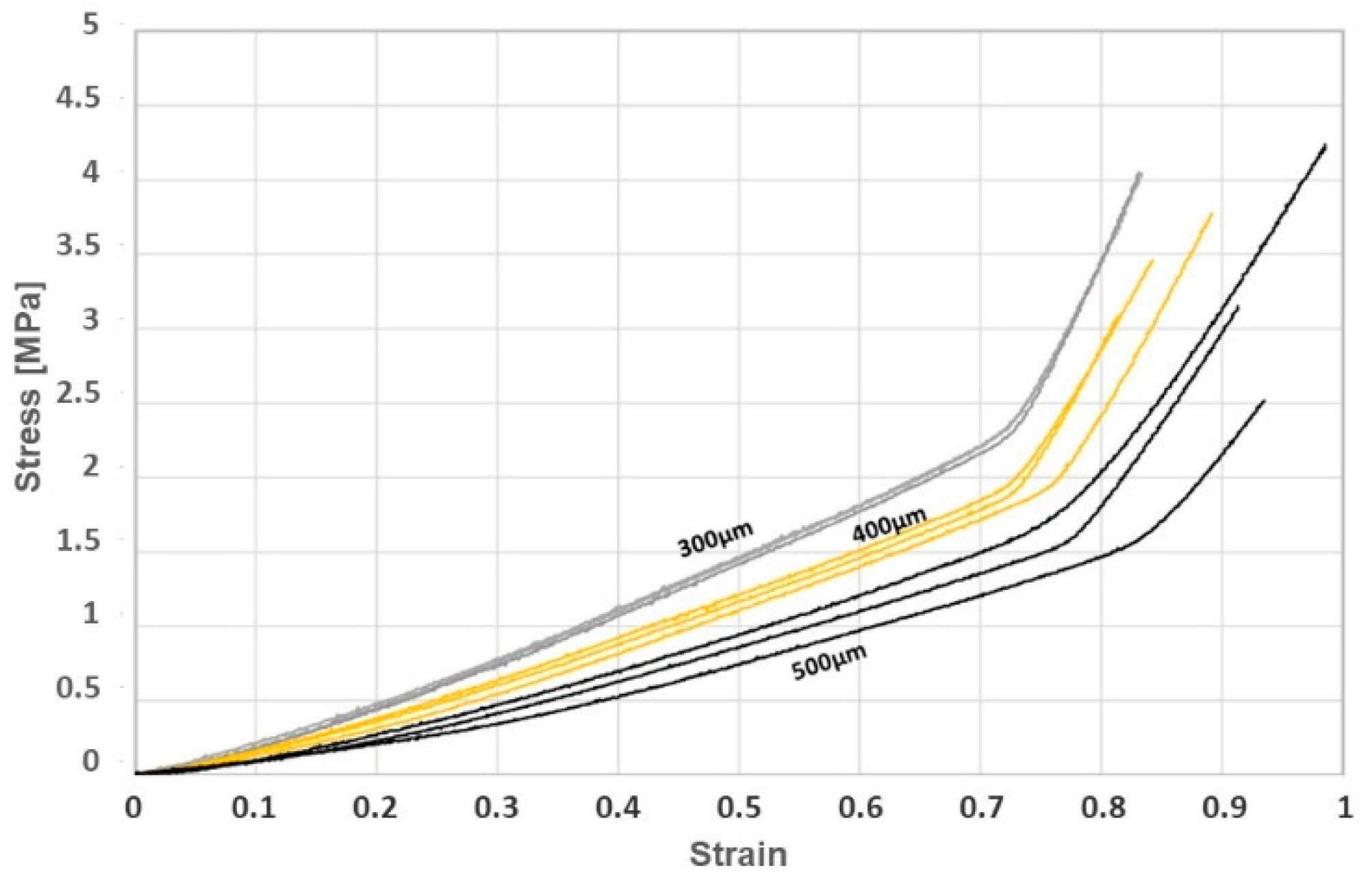
3.4. Mechanical Properties-Uniaxial Compression

Figure 7 shows the stress-strain curves for both 3D scaffolds (300; 400; 500 μm). The mechanical properties were analyzed based on uniaxial compression tests. The 3D scaffolds showed a compressive strength of 3.9 ± 0.1, 3.4 ± 0.3, and 3.3 ± 0.9 MPa; an elastics modulus of: 2.0 ± 0.3, 1.5 ± 0.2, 0.9 ± 0.1 MPa; and a maximum strain before crush of 82.8 ± 0.7, 84.9 ± 3.9, and 94.5 ± 3.7%. As shown in the following curves, Young’s modulus decreases with increasing mesh size. Thus, the higher the pore value, the less resistance to damage for the interior walls of the pieces in the yield. This becomes evident in the variability of the replicas corresponding to 500 μm. On the contrary, stiffness is higher, and repeatability of the replicas is very high in the other two sizes. This characteristic reveals that small pore sizes better support viscous stresses applied in the center, where buckling stresses are most critical. The lower Young’s modulus of all the 3D scaffolds suggests that the sample has a similar behavior under load, a higher elastic character and withstands greater deformation. The stress-strain curve shows a first elastic region until reaching 25–30% deformation, when the material behaves like a foam material (with a certain viscoelasticity). Subsequently, the curve presents an elastic zone where the densification remains practically constant up to the yield point. From there, a hardening takes place due to the deformation up to the crush of the structure without rupture. The mechanical properties obtained by the 3D scaffolds are similar to structures of hydroxyapatite, silica, and gelatine that have maximum strain stress of 3.8 ± 1.1 MPa or compositions of gelatine, carbox-ymethyl chitosan, and β-TCP with maximum values of 2.5 ± 0.2 MPa [43].

4. Conclusions

Despite the incipient unknowns, a new 3D scaffold for tissue engineering and bone regeneration has been designed based on FSI. Compared to the most currently used model in CFD-structural (k-ε or k-ω), the turbulence model comparison shows that the DES turbulence model is the most appropriate for this type of analysis. The external architecture of the 3D scaffolds was designed for specific additive manufacturing using the FDM technique (that is, a single layer to reduce the weight of the part to be implanted as much as possible). Thus, a geometric model was designed based on layers, disposing of an outer envelope, whose combination creates an internal architecture of micropores or hollows of different sizes (300, 400 and 500 µm) which are free of acute angles and sharp edges. The simulations carried out with two types of biocompatible materials, PEI-ULTEM 1010 and PLA (the latter being biodegradable), were stable against a bloodstream characterized by a high speed of 2 m·s−1. The bibliography had not collected such a high value for this parameter in the fluid-structural simulation. A value of 0.55 m·s−1 would be a valid hypothesis in normal conditions at the outlet of the aorta. Maximum values of up to 1.3 m·s−1 have been found in the mitral valve [44]. However, the speed with which a hemodialysis machine pumps blood is 2 m·s−1. Therefore, it is considered to be the most unfavorable case for the present study. Both materials had a similar behavior for the pore size corresponding to 400 µm per size model, especially in the WSS parameter. This data suggests the choice of this pore size as the most advisable in this type of 3D scaffold. On the contrary, there is a notable difference in the range of depressions in a pore size of 300 µm, which may be due to the difference of the drop pressure parameter. The attempts to print prototypes in PEI-ULTEM 1010 were unsuccessful due to the characteristics of the Fortus 450 MC printer, which prevented the generation of micropore sizes on such a low scale. It was also not possible to print the PEI-ULTEM1010 material in filament from the Ultimaker printer due to the temperature limitations present in this type of desktop printer. The technical application of microperforation using a femtosecond laser with a wavelength in the infrared and pulse width appropriate to the material is reserved as a future work for this material. This technique would be more recommended for the creation of such micropores on solid prismatic 3D scaffolds, which are non-viable by FDM using filaments. This solution would make its serial production viable.
The prototypes printed in PLA were successful, although it is possible to adapt its geometry much better using FDM to gain precision in its manufacture. The microscopic analysis revealed a large variation in the sizes of pore and extrusion layers, making their accuracy unpredictable. The contraction suffered in the deposition of the material is inversely proportional to the pore size. However, the search for this accuracy in geometry may be unnecessary considering that these 3D scaffolds, once implanted in the human or animal body, would lose their initial geometry relatively quickly to make way for tissue growth, which is also unpredictable. The mechanical properties obtained by the 3D scaffolds printed in PLA reveal that the Young’s modulus of the scaffolds are similar to similar pieces made of ceramic materials. Knowing the most suitable turbulence model for these complex geometries, as well as the most suitable material for the FDM technique and an approximate pore size, it will be necessary to apply some cell viability assays (ratio live/dead) in vitro and also in vivo.

Author Contributions

Conceptualization, methodology, software, investigation, writing—original draft preparation, review and editing, M.S. and C.J.L.-M. All authors have read and agreed to the published version of the manuscript.

Funding

This work was supported for publication by the “Conselleria de Innovación, Universidades, Ciencia y Sociedad Digital” of the Generalitat Valenciana. The authors would also like to thank the INGEGRAF association.

Institutional Review Board Statement

Not applicable.

Informed Consent Statement

Not applicable.

Data Availability Statement

Not applicable.

Acknowledgments

This work was funded by the Junta de Andalucía (Spanish Research group ref. TEP-181).

Conflicts of Interest

The authors declare no conflict of interest.

References

  1. Chen, H.; Liu, Y.; Wang, C.; Zhang, A.; Chen, B.; Han, Q.; Wang, J. Design and properties of biomimetic irregular scaffolds for bone tissue engineering. Comput. Biol. Med. 2021, 130, 104241. [Google Scholar] [CrossRef] [PubMed]
  2. Zhang, L.; Yang, G.; Johnson, B.N.; Jia, X. Three-dimensional (3D) printed scaffold and material selection for bone repair. Acta Biomater. 2019, 84, 16–33. [Google Scholar] [CrossRef]
  3. Shirzad, M.; Zolfagharian, A.; Matbouei, A.; Bodaghi, M. Design, evaluation, and optimization of 3D printed truss scaffolds for bone tissue engineering. J. Mech. Behav. Biomed. Mater. 2021, 120, 104594. [Google Scholar] [CrossRef]
  4. Huang, T.S.; Rahaman, M.N.; Doiphode, N.D.; Leu, M.C.; Bal, B.S.; Day, D.E.; Liu, X. Porous and strong bioactive glass (13–93) scaffolds fabricated by freeze extrusion technique. Mater. Sci. Eng. C 2011, 31, 1482–1489. [Google Scholar] [CrossRef]
  5. Cao, S.; Zhao, Y.; Hu, Y.; Zou, L.; Chen, J. New perspectives: In-situ tissue engineering for bone repair scaffold. Compos. Part B Eng. 2020, 202, 108445. [Google Scholar] [CrossRef]
  6. Wittkowske, C.; Reilly, G.C.; Lacroix, D.; Perrault, C.M. In Vitro Bone Cell Models: Impact of Fluid Shear Stress on Bone Formation. Front. Bioeng. Biotechnol. 2016, 4, 87. [Google Scholar] [CrossRef] [PubMed] [Green Version]
  7. Verbruggen, S.W.; Vaughan, T.J.; McNamara, L.M. Fluid flow in the osteocyte mechanical environment: A fluid-structure interaction approach. Biomech. Model. Mechanobiol. 2014, 13, 85–97. [Google Scholar] [CrossRef] [Green Version]
  8. Perinajová, R.; Juffermans, J.F.; Westenberg, J.J.M.; van der Palen, R.L.F.; van den Boogaard, P.J.; Lamb, H.J.; Kenjereš, S. Geometrically induced wall shear stress variability in CFD-MRI coupled simulations of blood flow in the thoracic aortas. Comput. Biol. Med. 2021, 133. [Google Scholar] [CrossRef]
  9. Tsuji, M.; Ishida, F.; Kishimoto, T.; Furukawa, K.; Miura, Y.; Shiba, M.; Sano, T.; Fukazawa, K.; Tanaka, K.; Tanemura, H.; et al. Double porous media modeling in computational fluid dynamics for hemodynamics of stent-assisted coiling of intracranial aneurysms: A technical case report. Brain Hemorrhages 2020, 1, 85–88. [Google Scholar] [CrossRef]
  10. Ouyang, P.; Dong, H.; He, X.; Cai, X.; Wang, Y.; Li, J.; Li, H.; Jin, Z. Hydromechanical mechanism behind the effect of pore size of porous titanium scaffolds on osteoblast response and bone ingrowth. Mater. Des. 2019, 183, 108151. [Google Scholar] [CrossRef]
  11. Ahmadi, S.M.; Yavari, S.A.; Wauthle, R.; Pouran, B.; Schrooten, J.; Weinans, H.; Zadpoor, A.A. Additively manufactured open-cell porous biomaterials made from six different space-filling unit cells: The mechanical and morphological properties. Materials 2015, 8, 1871–1896. [Google Scholar] [CrossRef] [Green Version]
  12. Liu, X.; Chen, M.; Luo, J.; Zhao, H.; Zhou, X.; Gu, Q.; Yang, H.; Zhu, X.; Cui, W.; Shi, Q. Biomaterials immunopolarization-regulated 3D printed-electrospun fibrous scaffolds for bone regeneration. Biomaterials 2021, 276, 121037. [Google Scholar] [CrossRef] [PubMed]
  13. Zamani, Y.; Amoabediny, G.; Mohammadi, J.; Seddiqi, H.; Helder, M.N.; Zandieh-Doulabi, B.; Klein-Nulend, J.; Koolstra, J.H. 3D-printed poly(Ɛ-caprolactone) scaffold with gradient mechanical properties according to force distribution in the mandible for mandibular bone tissue engineering. J. Mech. Behav. Biomed. Mater. 2020, 104, 103638. [Google Scholar] [CrossRef]
  14. Zhao, F.; Vaughan, T.J.; McNamara, L.M. Quantification of fluid shear stress in bone tissue engineering scaffolds with spherical and cubical pore architectures. Biomech. Model. Mechanobiol. 2016, 15, 561–577. [Google Scholar] [CrossRef] [Green Version]
  15. Mirkhalaf, M.; Wang, X.; Entezari, A.; Dunstan, C.R.; Jiang, X.; Zreiqat, H. Redefining architectural effects in 3D printed scaffolds through rational design for optimal bone tissue regeneration. Appl. Mater. Today 2021, 25, 101168. [Google Scholar] [CrossRef]
  16. Mendoza, L.D.; Vera, L.E.; Vera, L.E. Study of different turbulence models to obtain the curves characteristics of a naca profile 2415 through the three-dimensional simulation of fluid flows. Bistua Rev. La Fac. Ciencias Basicas 2019, 17, 43. [Google Scholar] [CrossRef]
  17. Shukla, S.; Singh, S.N.; Sinha, S.S.; Vijayakumar, R. Comparative assessment of URANS, SAS and DES turbulence modeling in the predictions of massively separated ship airwake characteristics. Ocean Eng. 2021, 229, 108954. [Google Scholar] [CrossRef]
  18. Tiftikçi, A.; Kocar, C. Investigation of turbulence models for a fully-periodic LWR unit-cell in lattice-Boltzmann framework. Prog. Nucl. Energy 2018, 104, 160–171. [Google Scholar] [CrossRef]
  19. Wei, H.; Chen, Y. Assessment of different turbulence models on the large scale internal heated water pool natural convection simulation. Ann. Nucl. Energy 2019, 131, 23–38. [Google Scholar] [CrossRef]
  20. Thompson, M.K.; Moroni, G.; Vaneker, T.; Fadel, G.; Campbell, R.I.; Gibson, I.; Bernard, A.; Schulz, J.; Graf, P.; Ahuja, B.; et al. Design for Additive Manufacturing: Trends, opportunities, considerations, and constraints. CIRP Ann.-Manuf. Technol. 2016, 65, 737–760. [Google Scholar] [CrossRef] [Green Version]
  21. Ngo, T.D.; Kashani, A.; Imbalzano, G.; Nguyen, K.T.Q.; Hui, D. Additive manufacturing (3D printing): A review of materials, methods, applications and challenges. Compos. Part B Eng. 2018, 143, 172–196. [Google Scholar] [CrossRef]
  22. Rainer, A.; Giannitelli, S.M.; Accoto, D.; De Porcellinis, S.; Guglielmelli, E.; Trombetta, M. Load-adaptive scaffold architecturing: A bioinspired approach to the design of porous additively manufactured scaffolds with optimized mechanical properties. Ann. Biomed. Eng. 2012, 40, 966–975. [Google Scholar] [CrossRef]
  23. Naing, M.W.; Chua, C.K.; Leong, K.F. Computer Aided Tissue Engineering Scaffold Fabrication BT—Virtual Prototyping & Bio Manufacturing in Medical Applications; Bidanda, B., Bártolo, P., Eds.; Springer: Boston, MA, USA, 2008; pp. 67–85. ISBN 978-0-387-68831-2. [Google Scholar]
  24. Almeida, H.A.; Bártolo, P.J. Tensile and shear stress evaluation of schwartz surfaces for scaffold design. Procedia Eng. 2015, 110, 167–174. [Google Scholar] [CrossRef]
  25. ISO. ISO/ASTM 52900: 2015 Additive Manufacturing—General Principles—Terminology; ISO: Geneva, Switzerland, 2017. [Google Scholar]
  26. Zakeri, S.; Vippola, M.; Levänen, E. A comprehensive review of the photopolymerization of ceramic resins used in stereolithography. Addit. Manuf. 2020, 35, 101177. [Google Scholar] [CrossRef]
  27. Paul, S. Finite element analysis in fused deposition modeling research: A literature review. Measurement 2021, 178, 109320. [Google Scholar] [CrossRef]
  28. Byberg, K.I.; Gebisa, A.W.; Lemu, H.G. Mechanical properties of ULTEM 9085 material processed by fused deposition modeling. Polym. Test. 2018, 72, 335–347. [Google Scholar] [CrossRef]
  29. Wang, C.; Huang, W.; Zhou, Y.; He, L.; He, Z.; Chen, Z.; He, X.; Tian, S.; Liao, J.; Lu, B.; et al. 3D printing of bone tissue engineering scaffolds. Bioact. Mater. 2020, 5, 82–91. [Google Scholar] [CrossRef] [PubMed]
  30. Vanaei, S.; Parizi, M.S.; Vanaei, S.; Salemizadehparizi, F.; Vanaei, H.R. An overview on materials and techniques in 3D bioprinting toward biomedical application. Eng. Regen. 2021, 2, 1–18. [Google Scholar] [CrossRef]
  31. Suffo, M. Determination of adhesive to be applied in the fabrication of prototypes using FDM techniques of 3D printing in component parts using ULTEMTM 1010. In Design Tools and Methods in Industrial Engineering; Springer: Berlin, Germany, 2020; pp. 959–969. ISBN 9783030311544. [Google Scholar]
  32. Suffo, M.; Vilches-Pérez, J.I.; Salido-Peracaula, M. Comparative analysis of the adhesion of metallic inserts on dental implants-prosthetic assembly generated by polymeric materials used for additive manufacturing. In Advances in Design Engineering; Lecture Notes in Mechanical Engineering; Springer: Berlin, Germany, 2020; Volume 1, pp. 245–253. ISBN 9783030411992. [Google Scholar]
  33. Suffo, M.; Revenga, C. Biomechanical analysis of non-metallic biomaterial in the manufacture of a new knee prosthesis. Materials 2021, 14, 5951. [Google Scholar] [CrossRef]
  34. Haley, A.L.; Valen-Sendstad, K.; Steinman, D.A. On delayed transition to turbulence in an eccentric stenosis model for clean vs. noisy high-fidelity CFD. J. Biomech. 2021, 125, 110588. [Google Scholar] [CrossRef]
  35. Yershov, S.V.; Yakovlev, V.A. The influence of mesh resolution on 3d rans flow simulations in Turbomachinery Flow Parts. Прoблемы машинoстрoения 2021, 13–27. [Google Scholar] [CrossRef]
  36. Celik, I.B.; Ghia, U.; Roache, P.J.; Freitas, C.J. Procedure for estimation and reporting of uncertainty due to discretization in CFD applications. J. Fluids Eng. ASME J. Fluids 2008, 130, 1–4. [Google Scholar] [CrossRef] [Green Version]
  37. Schlichting Hermann, K.G. Boundary-Layer Theory; Springer: Berlin/Heidelberg, Germany, 2017; ISBN 978-3-662-52917-1. [Google Scholar]
  38. SimScale CAE Forum. Available online: https://www.simscale.com/forum/t/what-is-y-yplus/82394 (accessed on 31 October 2021).
  39. Ali, D.; Ozalp, M.; Blanquer, S.B.G.; Onel, S. Permeability and fluid flow-induced wall shear stress in bone scaffolds with TPMS and lattice architectures: A CFD analysis. Eur. J. Mech. B/Fluids 2020, 79, 376–385. [Google Scholar] [CrossRef]
  40. WHITE PAPER—SABIC ULTEMTM Filament PERFORMANCE ASSESSMENT. Available online: https://www.sabic.com/en/products/specialties/filaments/ultem-filament (accessed on 6 September 2021).
  41. Wu, H.; Sulkis, M.; Driver, J.; Saade-Castillo, A.; Thompson, A.; Koo, J.H. Multi-functional ULTEMTM 1010 composite fi laments for additive manufacturing using Fused Filament Fabrication (FFF). Addit. Manuf. 2018, 24, 298–306. [Google Scholar] [CrossRef]
  42. Tang, X.; Qin, Y.; Xu, X.; Guo, D.; Ye, W.; Wu, W.; Li, R. Fabrication and in vitro evaluation of 3D printed porous polyetherimide scaffolds for bone tissue engineering. BioMed Res. Int. 2019, 2019, 2076138. [Google Scholar] [CrossRef] [PubMed]
  43. Martínez-Vázquez, F.J.; Cabañas, M.V.; Paris, J.L.; Lozano, D.; Vallet-Regí, M. Fabrication of novel Si-doped hydroxyapatite/gelatine scaffolds by rapid prototyping for drug delivery and bone regeneration. Acta Biomater. 2015, 15, 200–209. [Google Scholar] [CrossRef] [Green Version]
  44. Chirakarnjanakorn, S.; Tranchito, L.; Engelman, T.; Popović, Z.B.; Lascano, M.E.; Borowski, A.G.; Tang, W.W. Global longitudinal strain of left ventricle and tissue doppler velocity at mitral annulus are not significantly affected by changes in blood volume during hemodialysis session. J. Card. Fail. 2014, 20, S18. [Google Scholar] [CrossRef]
Figure 1. Classification according to the CFD methods calculation. DNS: direct numeric simulation; RANS: Reynolds average Navier–Stokes; RSM: Reynolds stress model; LES: large eddy simulation; SAS: scale adaptive simulation; DES: detached eddy simulation.
Applsci 12 00191 g001
Figure 2. The 3D scaffold, including an (a) isometric view and (b) basic dimensions. (c) Two domains: the enclosure domain and model domain.
Applsci 12 00191 g002
Figure 3. Graphic representation of the quantitative results obtained for each physical property evaluated.
Applsci 12 00191 g003
Figure 4. Comparative graphic representation of the results obtained for each physical property and pore sizes evaluated and applied on each material (PEI-ULTEM 1010 and PLA).
Applsci 12 00191 g004
Figure 5. Final geometry of the 3D scaffolds with 300, 400 and 500 µm pore size in PLA material.
Applsci 12 00191 g005
Figure 6. SEM analyses of 300, 400 and 500 µm. The figure contains images to measure the pore size, the molten layers deposited in the top view and the thickness of the 3D scaffolds in the cross-section view.
Applsci 12 00191 g006
Figure 7. Stress-strain curve for uniaxial compression test.
Applsci 12 00191 g007
Table 1. ULTEMTM AM1010F biocompatible used in this study.
XY 1XZ 1YZ 1
Tensile Modulus 2 [MPa] 275028652840
Tensile Stress 2 [MPa] 347380
Tensile Strain 2 [%] 43.81.3
Specific Gravity [g/cm3]1.27
1 The orientation of the coordinate axis (according to [40]). 2 v = 5 mm/min.
Table 2. PLA biocompatible used in this study.
Tensile Modulus 1 [MPa]3310
Tensile Stress 1 [MPa]110
Specific Gravity [g/cm3]1.24
1 v = 5 mm/min.
Table 3. Comparative results of the physical properties obtained when 5 different methods were applied.
K-ε
Realizable
K-ω
SST
Reynolds
Stress-ω
SASDES
K-ω SST
Surface pressure [Pa]
Applsci 12 00191 i001 Applsci 12 00191 i002 Applsci 12 00191 i003 Applsci 12 00191 i004 Applsci 12 00191 i005
Pressure profiles [Pa]
Applsci 12 00191 i006 Applsci 12 00191 i007 Applsci 12 00191 i008 Applsci 12 00191 i009 Applsci 12 00191 i010
Applsci 12 00191 i011
Velocity profiles [m· s−1]
Applsci 12 00191 i012 Applsci 12 00191 i013 Applsci 12 00191 i014 Applsci 12 00191 i015 Applsci 12 00191 i016
Applsci 12 00191 i017
Specific eddy kinetic energy [m2· s−2]
Applsci 12 00191 i018 Applsci 12 00191 i019 Applsci 12 00191 i020 Applsci 12 00191 i021 Applsci 12 00191 i022
Applsci 12 00191 i023
Von Mises stress [KPa]
Applsci 12 00191 i024 Applsci 12 00191 i025 Applsci 12 00191 i026 Applsci 12 00191 i027 Applsci 12 00191 i028
Applsci 12 00191 i029
Publisher’s Note: MDPI stays neutral with regard to jurisdictional claims in published maps and institutional affiliations.

