
The Effect of Acceleration on the Separation Force in Constrained-Surface Stereolithography


1
Department of Mechanical and Industrial Engineering, University of Illinois at Chicago, Chicago, IL 60607, USA
2
Computational Science Division and Leadership Computing Facility, Argonne National Laboratory, Lemont, IL 60439, USA
*
Author to whom correspondence should be addressed.
Appl. Sci. 2022, 12(1), 442; https://0-doi-org.brum.beds.ac.uk/10.3390/app12010442
Submission received: 15 October 2021
/
Revised: 19 December 2021
/
Accepted: 20 December 2021
/
Published: 3 January 2022
(This article belongs to the Topic Additive Manufacturing)
Abstract
:Constrained-surface-based stereolithography has recently attracted much attention from both academic and industrial communities. Despite numerous experimental, numerical and theoretical efforts, the fundamental need to reduce the separation force between the newly cured part and constrained surface has not yet been completely solved. In this paper, we develop a fluid dynamics approach, proposed in our previous work, to theoretically model the separation force in 3D printing of a cylindrical part for flat and patterned windows. We demonstrate the possibility of separation force reduction with an accelerated movement of the printing platform. In particular, we investigate behaviors of transient parameter, its reduction rate, and separation force reduction with respect to elevation speed and time. The proposed approach involves deceleration and acceleration stages and allows to achieve the force reduction for the entire printing process. Finally, we provide implicit analytical solutions for time moments when switching between the stages can be done without noticeable increase of separation force and explicit expression for separation force in case of patterned window.
1. Introduction
Additive manufacturing (AM) based on vat photopolymerization is one of the most promising 3D printing technologies for polymer-based products fabrication [1,2,3]. Among the various vat photopolymerization AM technologies, constrained-surface stereolithography (SL) is the most widely used one. It allows mass production in a wide size range (from millimeters to meters) and product commercialization. Compared to other polymer 3D printing technologies, such as fused deposition modeling (FDM), constrained surface SL has many advantages, such as high speed [4] and surface finish [5,6,7], multi-material fabrication capability [8,9], and high accuracy [6,10]. It has been successfully implemented in multiple industrial applications, varying from medicine and education to aerospace and consumer goods production.
Similar to other 3D printing technologies, constrained-surface SL starts from a three-dimensional (3D) computer-aided-design (CAD) model, which is then sliced into a set of two-dimensional (2D) layers. As its name implies, the constrained (liquid) surface is confined between the platform or the part being fabricated and the bottom (or top) surface of the liquid vat. The ultraviolet (UV) light beam can easily penetrate this transparent surface, focusing on the emerging part, and then curing the layer of the liquid polymer constrained in the region (Figure 1a). To separate the cured layer from the constrained surface and reconfine a new layer of a liquid resin for curing, the platform is elevated with a speed V. The process repeats until a 3D object is built.
Despite rapid development of constrained-surface SL, successful separation of the newly cured layer from the constrained surface is still the major challenge, limiting its applications. The extreme values of the separation force were primarily responsible for manufacturing failures [3,4,11,12,13,14]. Many researchers addressed this problem experimentally, to identify the key factors that affect the separation [4,13,14]. It turned out to be a complicated process, influenced by multiple parameters and geometry factors. Hence, modeling and simulation could be beneficial to tackle this problem resulting in lower labor costs and fabrication time. Liravi et al. [11] used a mechanical approach to develop a cohesive zone model (CZM) for the separation force. The authors employed bilinear cohesive law and considered the material loaded with pure normal tensile stress only. They also proposed an optimization scheme for constitutive cohesive stiffness parameters estimation. Ye et al. [15] proposed another CZM-based approach and demonstrated the efficiency of combining bilinear (for resonant values of force) and non-linear (for force values in the rest of the time interval) traction separation laws in predicting separation force-time profiles. Another approach, namely tilting separation, has been studied by Wu et al. in [12,16]. The authors developed a CZM-based approach for analytical prediction of the tilting separation force and verified it experimentally. This study revealed the critical importance of the cohesive curve in understanding the separation process under different conditions. Moreover, they modeled the key parameters of separation: cohesive stiffness, fracture energy, and maximal traction stress. It provided insights into the crucial differences between tilting and pulling-up separation. The vibration-assisted approach was proposed by Jin et al. [17,18] and also resulted in the separation force reduction. Most recently, Hu and co-workers developed a rotation-assisted model for constrained-surface SL and demonstrated its potential [19]. Several noticeable studies also considered the development of composites with improved performance [20,21,22,23,24]. However, approaches rather than mechanical to model the separation force remain mostly undeveloped. To fill this gap, in our previous work [25], we proposed a fluid-mechanics-based theoretical model to characterize the separation force in continuous 3D printing of a cylindrical part. However, the significant limitation imposed in that study was the constant elevation speed, rarely applicable for real fabrication processes. For up-to-date achievements and future prospects of 3D printing, an interested reader can refer to the recent literature [26,27,28].
In this paper, we investigate the behavior of the transient part of the separation force with respect to time t and elevation speed V and enhance the existing model [25] by incorporating acceleration in a control profile for the gap between the constrained surface and the bottom surface of the cured part. The paper is organized as follows. The general problem formulation is given in Section 2. The main results of this study are presented in Section 3. In particular, in Section 3.1. we refer to our previous work and study the behavior of the transient parameter, , incorporated in the separation force. The influence of the acceleration term added to the control profile for the gap is considered in Section 3.2. We further reveal that this approach leads to a dramatic increase in the separation force for the initial time interval ( s) of the printing process. We define the moment of time when this trend reverses (the separation force starts to decrease compared to the constant elevation speed case). In Section 3.3, we develop an approach to tackle the problem emerged in previous subsection and reduce the separation force for the initial time interval by means of deceleration of the printing platform. We further (Section 3.4) revisit another approach for the separation force reduction, namely the patterned window and obtain a refined expression for it. This expression simultaneously incorporates both the patterned-window and platform-acceleration (deceleration) approaches. Finally, the results of this study are summarized in Section 4.
2. Problem Formulation
The transient incompressible flow of a Newtonian fluid is described by the standard governing equations, which are the continuity equation, coupled to the momentum equation, given as follows:
where and p stand for velocity field and static pressure, respectively, and is a stress tensor given by:
No-slip boundary conditions at the walls and constant atmospheric pressure at the inlet of the constrained liquid layer are applied to the governing equations. Additionally, gravity is neglected and the bottom surface of the domain is considered rigid. The separation force, , is derived by integrating of the static pressure over the top surface :
Consider the printing of an axisymmetric cylindrical part (radius R). As shown in Figure 1b, we define a cylindrical coordinate system . In the simplest case, the Navier–Stokes equation for the radial component of the velocity reads as (assuming ):
with the initial and boundary conditions:
where and are the density and kinematic viscosity of the liquid resin, respectively, and h is the distance between the bottom surface of the printed part and constrained surface (further referred as “gap”).
3. Results and Discussion
3.1. Transient Parameter Properties
In our previous study [25] we solved (4) and (5) using separation of variables method and obtained an expression for the separation force in case of flat window:
where , , is the dynamic viscosity of the liquid resin, and with and standing for initial gap and elevation speed. It is worth noting that (6) is valid only in case of constant elevation speed, . The values of the parameter vary in a range and can also contribute to the reduction of separation force. As can be seen from (6), and, thus, the separation force can be in theory reduced by as . The behavior of with respect to elevation speed and time t is shown in Figure 2.
In particular, Figure 2a shows that an impact of on the separation force becomes not negligible for the values of the initial elevation speed mm/s. At the same time, Figure 2c demonstrates that the maximal values of with respect to initial elevation speed are achieved after s. However, the printing platform motion with the constant elevation speed limits significantly the practical applications of the separation force model.
3.2. Flat Window and Accelerated Printing Platform
Following the procedure proposed in [25], an expression for the separation force in case of arbitrary elevation speed, , can be obtained. Here we consider a case with the gap varying as and corresponding elevation speed, . Then the separation force reads as:
where and a is the acceleration of the printing platform. The behavior of the parameter with respect to initial elevation speed and time t are given in Figure 2b,d where the acceleration is fixed at mm/s. Interestingly, even for such a relatively low value of acceleration, the behavior of the parameter changes significantly compared to . In particular, the maximal value of is achieved approximately two times faster compared to . Moreover, the value of the initial elevation speed for which the value of the parameter becomes non-negligible, decreases as well. To better illustrate the difference between and , we introduced -reduction parameter, , given by:
The comparison of dependence on the initial elevation speed for different values of the acceleration is given in Figure 3.
The value of the -reduction parameter remains constant () for relatively low initial elevation speeds and drops dramatically with time. As the acceleration increases, the point where starts dropping shifts to the higher values of the initial elevation speeds, thus demonstrating the positive role of acceleration in decreasing parameter and consequent reduction of the separation force, as outlined below.
As the behavior of the transient parameter was defined, we proceeded with the optimization of the separation force. Let us introduce the non-dimensional force reduction parameter, , given by:
The time dependence of the parameter for different values of elevation speed varying from mm/s to mm/s is given in Figure 4. In top (a–d) and bottom (e–h) rows the cases of 1 mm and 10 m initial gaps are compared. It was observed that for the relatively large initial gap the acceleration of the moving platform led to the resonant increase of the separation force. The effect, however reversed after several seconds and the separation force started to drop. In contrast, for a relatively small initial gap this effect was almost negligible, as can be seen from the bottom row of Figure 4e–h. The ranges of elevation speed and acceleration correspond to previous experimental studies [13]. The minimal value of the separation force reduction, , with respect to time, t, derived from and given by:
where A and B stand for:
We can also obtain the values of t, where . Let us introduce non-dimensional quantities and . By solving , we arrive at:
We define C in such a way that , otherwise , provided that . This imposes a limitation on , which is equivalent to . As expected (Figure 4), there are two solutions, one is trivial, another is given in an implicit form:
Here we assume that , i.e., that is valid for relatively small values of t ( s). If that is not the case, an implicit solution is (aside the trivial):
As can be seen from Figure 4a–d, it is not efficient to accelerate the moving part for , since it causes the significant increase of the separation force, which has the highest values in this time interval. The simple solution of this problem is to keep the elevation speed constant up to and add an acceleration for . However, the reduction of the separation force can be achieved for interval via deceleration of the moving part, as outlined in the next section.
3.3. Flat Window and Decelerated Printing Platform
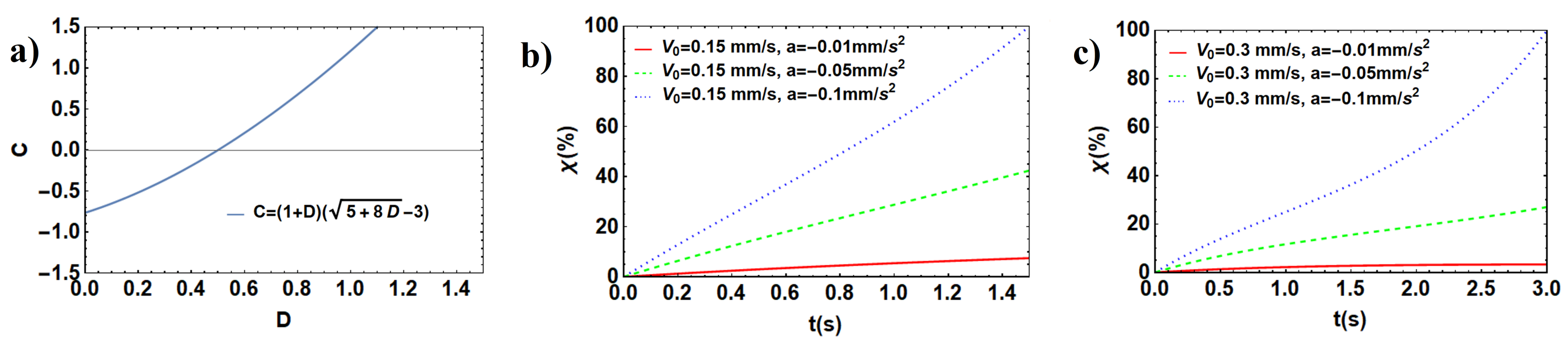
We will now proceed with decelerated moving platform to reduce the separation force for . The dependence , given by (12) is shown in Figure 5a. As can be seen from it, for , which corresponds to the case of acceleration, whereas for , which corresponds to the case of deceleration. The lower limit of D () was imposed provided that .
3.4. Patterned Window
The concept of flat window patterned with radially symmetrical grooves has been proven to be beneficial to control liquid flow dynamics and alter pressure gradients [29,30,31,32,33,34,35,36,37,38], as well as for the separation force reduction [10,25,39,40], both theoretically and experimentally. These studies revealed that the grooves were capable of increasing flow by augmentation of the cross section of the pathway. We recently proposed a model [25] to estimate the separation force for the patterned window. The model employs the concept of an effective gap, :
and is based on the analytical solution for a flat window. Here , ,, and stand for initial gap for the flat window, height of the grooves, total area of the bottom surfaces of the grooves, total area of the flat window, and fitting function dependent on the geometry of the grooves, respectively. The concept capitalizes on mass conservation of the fluid domain formed by the patterned window and the equivalent flat window with the larger initial gap attributed to the presence of grooves. An exact form of fitting parameter depends on the geometry of the window. For instance, if the window is patterned with radially symmetrical grooves, it depends on the number, depth, and shape of the grooves. In particular, for rectangular and triangular grooves, can be approximated by [25]:
where with and standing for the maximal value of the separation force for a flat window estimated from (6) and the maximum value of the separation force for the patterned window obtained from the simulation/experiment, respectively. An explicit dependence of on the window geometry is given by parameter . For instance, in case of radially symmetrical rectangular grooves, the dependence on the number of grooves, n, is given by:
where corresponds of the window completely covered with grooves and is the fitting parameter. Once the concept of effective gap was implemented, an expression for the separation force becomes:
Table 1 summarizes all the parameters introduced in this study. There are two types of parameters: constants and functions. Elevation speed, V, and gap height, h are both time-dependent.
Finally, we would like to emphasize the following. As mentioned above, multiple times, this study is a development of our previous one [25]. The latter provided a numerical verification of the proposed method. An expression for the separation force derived in this study has the functional form similar to that in [25]. Thus, we consider the approach developed here sufficiently justified. An interested reader can refer to [13], where an experimental approach for measuring the separation force in a constrained-surface SL process is described in detail.
4. Conclusions
In this study, we considered the influence of the printing platform acceleration on the separation force in a constrained-surface stereolithography process. There were two reasons for introducing acceleration. First, it allowed more accurate modeling of a real printing process since the constant elevation of the printing platform was rare. Second, platform acceleration was employed to potentially reduce the separation force.
Indeed, we developed a theoretical model to predict the separation force for printing a cylindrical part. We considered the behavior of three parameters, namely transient parameter, its reduction, and separation force reduction, as functions of time and elevation speed. In particular, we demonstrated that transient parameter optimization resulted in up to a two-fold reduction of the separation force. However, it was important how fast the optimal value of the transient parameter could be achieved. We demonstrated that, in case of an accelerated platform motion, the process takes much less time compared to constant elevation (approximately up to two orders of magnitude). The dynamics of the separation force reduction parameter was also in favor of the positive effect of acceleration on separation force reduction. Moreover, a ten-fold increase of the acceleration resulted in up to a three-fold decrease in separation force. We also investigated both flat and patterned windows and demonstrated the possibility of significantly reducing the separation force for the continuous 3D printing process. At the same time, a more complex acceleration algorithm was suggested. In particular, providing an initial non-zero elevation speed, the platform should be decelerated for relatively small times, and accelerated later on. This algorithm resulted in efficient separation force reduction compared to constant elevation.
In future studies, this model can be generalized in terms of geometry (fabrication of arbitrary-shaped parts) and resin properties. In particular, resins possessing non-Newtonian properties (for instance, seeded with magnetic particles) can be considered.
Author Contributions
Conceptualization, D.G. and J.X.; methodology, D.G.; software, D.G.; validation, J.X. and R.P.; formal analysis, D.G.; investigation, D.G.; resources, J.X.; writing–original draft preparation, D.G.; writing–review and editing, J.X. and R.P.; funding acquisition, J.X. and R.P. All authors have read and agreed to the published version of the manuscript.
Funding
This work was supported by the National Science Foundation through grant #1563477, titled “Layerless Additive Manufacturing of 3D Objects with Wide Solid Cross Sections”, awarded to Y. Pan and J.Xu, by the Argonne National Laboratory, through grant # ANL 0J-60008-0019A, titled “High-performance computing and physics-informed machine learning for multiscale flows”, awarded to R. Paoli, and by the National Science Foundation, through grant #1854815, titled “High-Performance Computing and Data-Driven Modeling of Aircraft Contrails”, awarded to R. Paoli.
Institutional Review Board Statement
Not applicable.
Informed Consent Statement
Not applicable.
Data Availability Statement
Not applicable.
Conflicts of Interest
The authors declare no conflict of interest.
References
- Jacobs, P.F. Rapid Prototyping & Manufacturing: Fundamentals of Stereolithography; Society of Manufacturing Engineers: Southfield, MI, USA, 1992. [Google Scholar]
- Bártolo, P.J. Stereolithographic processes. In Stereolithography; Springer: Berlin/Heidelberg, Germany, 2011; pp. 1–36. [Google Scholar]
- Gibson, I.; Rosen, D.; Stucker, B. Additive Manufacturing Technologies: 3D Printing, Rapid Prototyping, and Direct Digital Manufacturing; Springer: Berlin/Heidelberg, Germany, 2014. [Google Scholar]
- Pan, Y.; Zhou, C.; Chen, Y. A fast mask projection stereolithography process for fabricating digital models in minutes. J. Manuf. Sci. Eng. 2012, 134, 051011. [Google Scholar] [CrossRef]
- Pan, Y.; Chen, Y. Meniscus process optimization for smooth surface fabrication in Stereolithography. Addit. Manuf. 2016, 12, 321–333. [Google Scholar] [CrossRef]
- Pan, Y.; Chen, Y. Smooth surface fabrication based on controlled meniscus and cure depth in microstereolithography. J. Micro Nano Manuf. 2015, 3, 031001. [Google Scholar] [CrossRef]
- Pan, Y.; Zhao, X.; Zhou, C.; Chen, Y. Smooth surface fabrication in mask projection based stereolithography. J. Manuf. Process. 2012, 14, 460–470. [Google Scholar] [CrossRef]
- Lu, L.; Guo, P.; Pan, Y. Magnetic-Field-Assisted Projection Stereolithography for Three-Dimensional Printing of Smart Structures. J. Manuf. Sci. Eng. 2017, 139, 071008. [Google Scholar] [CrossRef]
- Pan, Y.; Patil, A.; Guo, P.; Zhou. A novel projection based electro-stereolithography (PES) process for production of 3D polymer-particle composite objects. Rapid Prototyp. J. 2017, 23, 236–245. [Google Scholar] [CrossRef]
- Pan, Y.; Chen, Y.; Yu, Z. Fast Mask Image Projection-Based Micro-Stereolithography Process for Complex Geometry. J. Micro Nano Manuf. 2017, 5, 014501. [Google Scholar] [CrossRef]
- Liravi, F.; Das, S.; Zhou, C. Separation force analysis and prediction based on cohesive element model for constrained-surface stereolithography processes. Comput. Aided Des. 2015, 69, 134–142. [Google Scholar] [CrossRef]
- Wu, X.; Lian, Q.; Li, D.; Jin, Z. Tilting separation analysis of bottom-up mask projection stereolithography based on cohesive zone model. J. Mater. Process. Technol. 2017, 243, 184–196. [Google Scholar] [CrossRef] [Green Version]
- Pan, Y.; He, H.; Xu, J.; Feinerman, A. Study of separation force in constrained surface projection stereolithography. Rapid Prototyp. J. 2017, 23, 353–361. [Google Scholar] [CrossRef] [Green Version]
- Huang, Y.M.; Jiang, C.P. On-line force monitoring of platform ascending rapid prototyping system. J. Mater. Process. Technol. 2005, 159, 257–264. [Google Scholar] [CrossRef]
- Ye, H.; Venketeswaran, A.; Das, S.; Zhou, C. Investigation of separation force for constrained-surface stereolithography process from mechanics perspective. Rapid Prototyp. J. 2017, 23, 696–710. [Google Scholar] [CrossRef]
- Wu, X.; Xu, C.; Zhang, Z.; Jin, Z. Tilting separation simulation and theory verification of mask projection stereolithography process. Rapid Prototyp. J. 2021. [Google Scholar] [CrossRef]
- Jin, J.; Yang, J.; Mao, H.; Chen, Y. A vibration-assisted method to reduce separation force for stereolithography. J. Manuf. Process. 2018, 34, 793–801. [Google Scholar] [CrossRef]
- Xu, Y.; Zhu, Y.; Sun, Y.; Jin, J.; Chen, Y. A Vibration-Assisted Separation Method for Constrained-Surface-Based Stereolithography. J. Manuf. Sci. Eng. 2021, 143, 051008. [Google Scholar] [CrossRef]
- Hu, M.; Cheng, H.; Feng, Y. Rotation-Assisted Separation Model of Constrained-Surface Stereolithography. 3D Print. Addit. Manuf. 2021. [Google Scholar] [CrossRef]
- Ouyang, J.; Zhao, Z.; Yang, H.; Zhang, Y.; Tang, A. Large-scale synthesis of sub-micro sized halloysite-composed CZA with enhanced catalysis performances. Appl. Clay Sci. 2018, 152, 221–229. [Google Scholar] [CrossRef]
- Corrado, A.; Polini, W. Measurement of high flexibility components in composite material by touch probe and force sensing resistors. J. Manuf. Process. 2019, 45, 520–531. [Google Scholar] [CrossRef]
- Wang, F.; Xie, Z.; Liang, J.; Fang, B.; Piao, Y.; Hao, M.; Wang, Z. Tourmaline-modified FeMnTiO x catalysts for improved low-temperature NH3-SCR performance. Environ. Sci. Technol. 2019, 53, 6989–6996. [Google Scholar] [CrossRef]
- Piao, Y.; Jiang, Q.; Li, H.; Matsumoto, H.; Liang, J.; Liu, W.; Pham-Huu, C.; Liu, Y.; Wang, F. Identify Zr promotion effects in atomic scale for co-based catalysts in Fischer–Tropsch synthesis. ACS Catal. 2020, 10, 7894–7906. [Google Scholar] [CrossRef]
- Bocci, E.; Prosperi, E.; Mair, V.; Bocci, M. Ageing and cooling of hot-mix-asphalt during hauling and paving—A laboratory and site study. Sustainability 2020, 12, 8612. [Google Scholar] [CrossRef]
- Gritsenko, D.; Yazdi, A.; Lin, Y.; Hovorka, V.; Pan, Y.; Xu, J. On characterization of separation force for resin replenishment enhancement in 3D printing. Addit. Manuf. 2017, 20, 151–156. [Google Scholar] [CrossRef]
- Pereira, G.R.; Gasi, F.; Lourenço, S.R. Review, Analysis, and Classification of 3D Printing Literature: Types of Research and Technology Benefits. Int. J. Adv. Eng. Res. Sci. 2019, 6, 167–187. [Google Scholar] [CrossRef] [Green Version]
- Rath, U.; Pandey, P.M. Towards an Improved Understanding of Stereolithography Process—A Computational Study. Adv. Comput. Meth. Manuf. 2019, 403–413. [Google Scholar]
- Zhang, F.; Zhu, L.; Li, Z.; Wang, S.; Shi, J.; Tang, W.; Li, N.; Yang, J. The recent development of vat photopolymerization: A review. Addit. Manuf. 2021, 48, 102423. [Google Scholar] [CrossRef]
- Kukulka, D.J.; Devgun, M. Fluid temperature and velocity effect on fouling. Appl. Therm. Eng. 2007, 27, 2732–2744. [Google Scholar] [CrossRef]
- Srinivasan, S.; Kleingartner, J.A.; Gilbert, J.B.; Cohen, R.E.; Milne, A.J.; McKinley, G.H. Sustainable drag reduction in turbulent Taylor-Couette flows by depositing sprayable superhydrophobic surfaces. Phys. Rev. Lett. 2015, 114, 014501. [Google Scholar] [CrossRef] [PubMed] [Green Version]
- Xu, L. Liquid drop splashing on smooth, rough, and textured surfaces. Phys. Rev. E 2007, 75, 056316. [Google Scholar] [CrossRef] [Green Version]
- Shastry, A.; Case, M.J.; Böhringer, K.F. Directing droplets using microstructured surfaces. Langmuir 2006, 22, 6161–6167. [Google Scholar] [CrossRef]
- Quéré, D.; Lafuma, A.; Bico, J. Slippy and sticky microtextured solids. Nanotechnology 2003, 14, 1109. [Google Scholar]
- Bruzzone, A.; Costa, H.; Lonardo, P.; Lucca, D. Advances in engineered surfaces for functional performance. CIRP Ann. Manuf. Techn. 2008, 57, 750–769. [Google Scholar] [CrossRef]
- Nicolaiewsky, E.M.; Fair, J.R. Liquid flow over textured surfaces. 1. Contact angles. Ind. Eng. Chem. Res. 1999, 38, 284–291. [Google Scholar] [CrossRef]
- Pettersson, U.; Jacobson, S. Influence of surface texture on boundary lubricated sliding contacts. Tribol. Int. 2003, 36, 857–864. [Google Scholar] [CrossRef]
- Smith, J.D.; Dhiman, R.; Anand, S.; Reza-Garduno, E.; Cohen, R.E.; McKinley, G.H.; Varanasi, K.K. Droplet mobility on lubricant-impregnated surfaces. Soft Matter 2013, 9, 1772–1780. [Google Scholar] [CrossRef] [Green Version]
- Lee, C.; Kim, C.J. Underwater restoration and retention of gases on superhydrophobic surfaces for drag reduction. Phys. Rev. Lett. 2011, 106, 014502. [Google Scholar] [CrossRef] [Green Version]
- Jiang, Y.; Wang, Y.; Lichade, K.; He, H.; Feinerman, A.; Pan, Y. Textured window design for continuous projection stereolithography process. Manuf. Lett. 2020, 24, 87–91. [Google Scholar] [CrossRef]
- Jiang, Y.; Wang, Y.; He, H.; Feinerman, A.; Pan, Y. Constrained Window Design in Projection Stereolithography for Continuous Three-Dimensional Printing. 3D Print. Addit. Manuf. 2020, 7, 163–169. [Google Scholar] [CrossRef]
Figure 1.
Fabrication explained (a) scheme of constrained-surface stereolithography (b) domain definition.
Figure 1.
Fabrication explained (a) scheme of constrained-surface stereolithography (b) domain definition.

Figure 2.
The dependence of transient parameter (a) from the time for the different values of the initial elevation speed; (b) from the time for the different values of the initial elevation speed; (c) from the elevation speed for the different moments of time; (d) from the elevation speed for the different moments of time. The initial gap m.

Figure 3.
-reduction as a function of the initial elevation speed for (a) mm/s (b) mm/s (c) mm/s. The initial gap m.
Figure 3.
-reduction as a function of the initial elevation speed for (a) mm/s (b) mm/s (c) mm/s. The initial gap m.

Figure 4.
The reduction of the separation force due to acceleration with time for (a) mm, mm/s (b) mm, mm/s (c) mm, mm/s (d) mm, mm/s (e) m, mm/s (f) m, mm/s (g) m, mm/s (h) m, mm/s.
Figure 4.
The reduction of the separation force due to acceleration with time for (a) mm, mm/s (b) mm, mm/s (c) mm, mm/s (d) mm, mm/s (e) m, mm/s (f) m, mm/s (g) m, mm/s (h) m, mm/s.

Figure 5.
Effect of deceleration on separation force reduction: (a) non-dimensional parameter C as a function of non-dimensional parameter D (b) for mm, mm/s, mm/s (c) for mm, mm/s, mm/s.
Figure 5.
Effect of deceleration on separation force reduction: (a) non-dimensional parameter C as a function of non-dimensional parameter D (b) for mm, mm/s, mm/s (c) for mm, mm/s, mm/s.


Table 1.
Key parameters.
| Parameter | Description | Parameter | Description | Parameter | Description |
|---|---|---|---|---|---|
| transition parameter () | a | platform acceleration | A | auxiliary function | |
| transition parameter () | h | gap height | B | auxiliary function | |
| inversed dynamic viscosity (resin) | initial gap | C | auxiliary function | ||
| fitting function (groove geometry) | effective gap | D | auxiliary function | ||
| fitting function (groove number) | groove height | max separation force (flat window) | |||
| force ratio | n | number of grooves | max separation force (patterned window) | ||
| -reduction | max number of grooves | separation force () | |||
| dynamic viscosity (resin) | p | static pressure | separation force () | ||
| kinematic viscosity (resin) | r | radial coordinate | R | part radius | |
| mass density (resin) | t | running time | total window area (flat) | ||
| stress tensor | velocity field | total groove area (bottom) | |||
| force reduction | radial velocity | V | elevation speed | ||
| groove number fitting coefficient | z | axial coordinate | initial elevation speed |
Publisher’s Note: MDPI stays neutral with regard to jurisdictional claims in published maps and institutional affiliations. |
© 2022 by the authors. Licensee MDPI, Basel, Switzerland. This article is an open access article distributed under the terms and conditions of the Creative Commons Attribution (CC BY) license (https://creativecommons.org/licenses/by/4.0/).
Share and Cite
MDPI and ACS Style
Gritsenko, D.; Paoli, R.; Xu, J. The Effect of Acceleration on the Separation Force in Constrained-Surface Stereolithography. Appl. Sci. 2022, 12, 442. https://0-doi-org.brum.beds.ac.uk/10.3390/app12010442
AMA Style
Gritsenko D, Paoli R, Xu J. The Effect of Acceleration on the Separation Force in Constrained-Surface Stereolithography. Applied Sciences. 2022; 12(1):442. https://0-doi-org.brum.beds.ac.uk/10.3390/app12010442
Chicago/Turabian StyleGritsenko, Dmitry, Roberto Paoli, and Jie Xu. 2022. "The Effect of Acceleration on the Separation Force in Constrained-Surface Stereolithography" Applied Sciences 12, no. 1: 442. https://0-doi-org.brum.beds.ac.uk/10.3390/app12010442
Note that from the first issue of 2016, this journal uses article numbers instead of page numbers. See further details here.