
Task-Oriented Motion Planning of a Space Manipulator under Multiple Constraints


1
Beijing Key Laboratory of Intelligent Space Robotic System Technology and Applications, Beijing Institute of Spacecraft System Engineering, Beijing 100094, China
2
School of Automation, Beijing University of Posts and Telecommunications, Beijing 100876, China
*
Author to whom correspondence should be addressed.
Appl. Sci. 2022, 12(11), 5369; https://doi.org/10.3390/app12115369
Submission received: 21 March 2022
/
Revised: 15 May 2022
/
Accepted: 24 May 2022
/
Published: 26 May 2022
(This article belongs to the Section Robotics and Automation)
Abstract
:During task execution by a space manipulator, many factors need to be considered, such as joint motion range, external environment interference, running speed and task time. Studying the motion planning strategy under multi-constraint conditions is important for optimizing the task flow of the manipulator and improving the planning autonomy. Aiming at this, this paper proposes a method based on a hierarchical task network which has the ability to connect non-adjacent nodes of topology when generating the best path; it also carries out the control simulation of traditional path planning of a manipulator for typical tasks and the latter two working conditions using an optimal task planning method. The results show that this method is effective for realizing the Cartesian spatial task planning of a manipulator under multiple constraints and has important on-orbit application significance for improving the continuous autonomy of task completion.
1. Introduction
As a new type of aerospace equipment, the space manipulator works mostly in a narrow, complex and lack-of-supply working environment. The cost of energy supply and maintenance is high, so its movement process is subject to a variety of constraints from itself and the outside world. On the other hand, limited by the performance of the on-board computer and the reliability requirements of the on-orbit control system, the space manipulator usually only carries several basic path planning algorithms.
Multi-constraint task planning of a space manipulator refers to finding the behavior sequence and motion path of the manipulator from the initial state to the target state with the given initial conditions (including the initial state of the manipulator), constraint set (including environmental constraints, running time, energy consumption, intermediate point, etc.) and target set (including the target position and the attitude of the manipulator).
Aiming at the complex on-orbit task requirements, the on-orbit task execution autonomy of a space manipulator is becoming more and more important [1]. In the process of task execution, many factors, such as joint motion range, external environment interference, running speed and time, need to be considered. If this is done by only relying on human selection, it is difficult to obtain ideal planning path and results. A motion planning strategy considering multi-constraint conditions for different tasks is an inevitable choice to optimize the results of the manipulator motion planning and improve the autonomy of task planning.
For a manipulator used on a space station, its application environment is known. Therefore, the global motion planning method is more suitable for this kind of manipulator. The global path planning method consists in planning a motion path for the robot from the starting point to the end point according to the known global environment information. The accuracy of planning the path depends on the accuracy of obtaining environmental information. This method can usually find the optimal solution, but accurate global environment information has to be available in advance. The methods based on environmental modeling mainly include the free space method, the configuration space method and the grid method.
The free space method uses predefined basic shapes such as generalized cone [2] and convex polygon [3] to construct the free space, represents the free space as a connected graph, and then carries out path planning by searching the connected graph. This method is flexible. Even if the starting point and target point change, there is no need to reconstruct the connected graph, but the complexity of the algorithm is directly proportional to the number of obstacles and it cannot guarantee that the shortest path can be obtained in any case. Therefore, this method is only suitable for situations where the path accuracy and the robot speed are not high.
In order to simplify the problem, the configuration space method usually reduces the robot to one point and expands the obstacles around it proportionally, so that the robot can move freely in the obstacle space without colliding with the obstacles and their boundaries. At present, there are well-developed visual graph methods [4] and optimization algorithms (such as the Dijkstra method [5], the A* search algorithm [6], etc.).
The grid method [7] decomposes the working environment of the robot into a series of grid cells with binary information and assumes that the position and size of obstacles in the workspace are known and will not change during the movement of the robot. The two-dimensional workspace of the robot is planned with a grid of the same size, and the grid size depends on the size of the robot itself. The grid method records environmental information in the units of the grid. The size of the grid has an important impact on the size of environmental information storage and the length of the planning time. With a large grid division, the storage of environmental information is small, and the planning time is short, but the resolution is low; in the opposite situation, the resolution is high, but the planning time is long.
For a robot motion control with a complex external environment and multiple constraints, it is difficult to describe the target state and the global environment directly and quickly. Therefore, some scholars have proposed a better task planner, the hierarchical task network (HTN) [8,9]. The HTN planner decomposes the original task into several atomic tasks that can be executed directly. Mosteo et al. [10] proposed a task planner based on an HTN planning framework for multi-robot cooperative tasks. Lozano Perez et al. [11] proposed a task and motion planning method based on symbolic search, which solves decision-making problems such as grasping position, placement position and moving path under geometric constraints. However, the geometric constraint solver used in the algorithm requires a long preprocessing time, reducing the planning efficiency. The on-board computer used in the space manipulator cannot bear such a large amount of calculation. The above algorithms are aimed at joint space planning and are not applicable when there are strict requirements for end posture. In addition, they only provide the action sequence and do not reasonably plan the action details, so they cannot be directly used in the robot control system.
To study the disassembly and planning methods for complex tasks of a space manipulator, it is important to improve the autonomy of the space manipulator. This study used an improved HTN theory to design a manipulator task planning algorithm to improve the task execution efficiency. HTN planning adopts the idea of task decomposition to disassemble complex non-original tasks layer by layer into original tasks that can be directly executed by actuators. HTN abstracts the target state of the task into the target task. The task has a complex to simple layered structure, and the lowest layer is the original task that can no longer be decomposed. HTN consists of the “operator set” of the original task and the “method set” of the disassembly of the composite task. Given the target task and the current environment state, the planner uses the methods in the planning domain to simplify the task and provide a feasible basic action sequence.
The rest of the paper is organized as follows: In Section 2, HTN fundamentals are introduced. In Section 3, we present the general idea of the research. In Section 4, the mission profile of the space manipulator is analyzed. The task intermediate point planning is modeled in Section 5. The mission planning simulation is described in Section 6, and conclusions are summarized in Section 7.
2. HTN Fundamentals
2.1. Classification of the Tasks
- (1)
- Goal tasks: tasks to be realized.
- (2)
- Primitive tasks: tasks that can be completed directly by performing corresponding actions, such as moving a stool or turning on a switch.
- (3)
- Compound tasks: consider expected changes and include multiple-target tasks and original tasks.
Target tasks and composite tasks are called non-original tasks.
2.2. Planner Input
- (1)
- An initial “task network” that represents the problem to be solved. A “task network” is a collection of “tasks”, representing what needs to be done. Each “task” has a name and a parameter list, which can be scalar or constant. Some tasks are “original” (for example, they can be executed directly), while others are “non-original” (for example, how to execute them needs to be solved in the planning period). The task network also contains the constraints of the task (which will limit the value range of some variables) and some rules in task execution.
- (2)
- An “operator” set that describes the execution effect of each original task (or action).
- (3)
- A collection of “methods” that describe how to perform various non-original tasks. Each mode is a parameter pair: , where is a task, and is a task network. It can be said that executing the task network described in is a way to complete task (assuming that there is an execution mode that meets all constraints).
- (4)
- Initial state (as an input, it exists objectively).
- (5)
- Among them, operators and methods are important components of the planner. They constitute the planning domain. The planner looks for the method to solve the problem, so that the general planning algorithm has the means to deal with the problems in specific fields.
2.3. Planner Algorithm
The HTN theory provides a planning idea suitable for any field. The planning process starts from the initial task network and repeatedly performs the following steps until there are no more non-original tasks:
- (1)
- Find a non-original task in and a method in , where is consistent with .
- (2)
- Change by “decomposing” (replace with the task in and merge the constraints of and ).
- (3)
- Once the non-original task no longer exists in , the next problem is to find a completely ordered instance of that satisfies all constraints. If the above operation can be carried out, is a successful planning result of the original problem.
In a given task network, the interaction between tasks is inevitable. Two tasks connected by an interaction interact with each other, and some interactions are beneficial, while others are harmful [16]. These bad interactions cause conflicts between tasks. For example, the results of one task may cause another task to lose its preconditions, or the results of two tasks may conflict with each other’s preconditions. There is no general method to deal with conflict in HTN. According to the type of conflict and the field of planning problem, some conflicts can be solved by adding new constraints, while others cannot be solved, resulting in the failure of task planning [17,18,19].
The specific steps of a general planning algorithm are as follows:
Step 1, Input planning problem .
Step 2, If contains only the original task, resolve the conflict in and return the result. If the conflict cannot be resolved, failure is returned.
Step 3, Select a non-original task in .
Step 4, Select an extension for .
Step 5, Simplify the task by replacing with the extension in Step 4.
Step 6, The evaluation mechanism is used to find the interaction conflict in task , and the possible handling methods are given.
Step 7, Apply a processing method in Step 6.
Step 8, Go to Step 2.
3. General Idea of the Research
The structure of the space manipulator is shown in Figure 1. The joints are numbered as 1 − n successively and indicated as . denotes the coordinate system of , and denotes the inertial coordinate system.
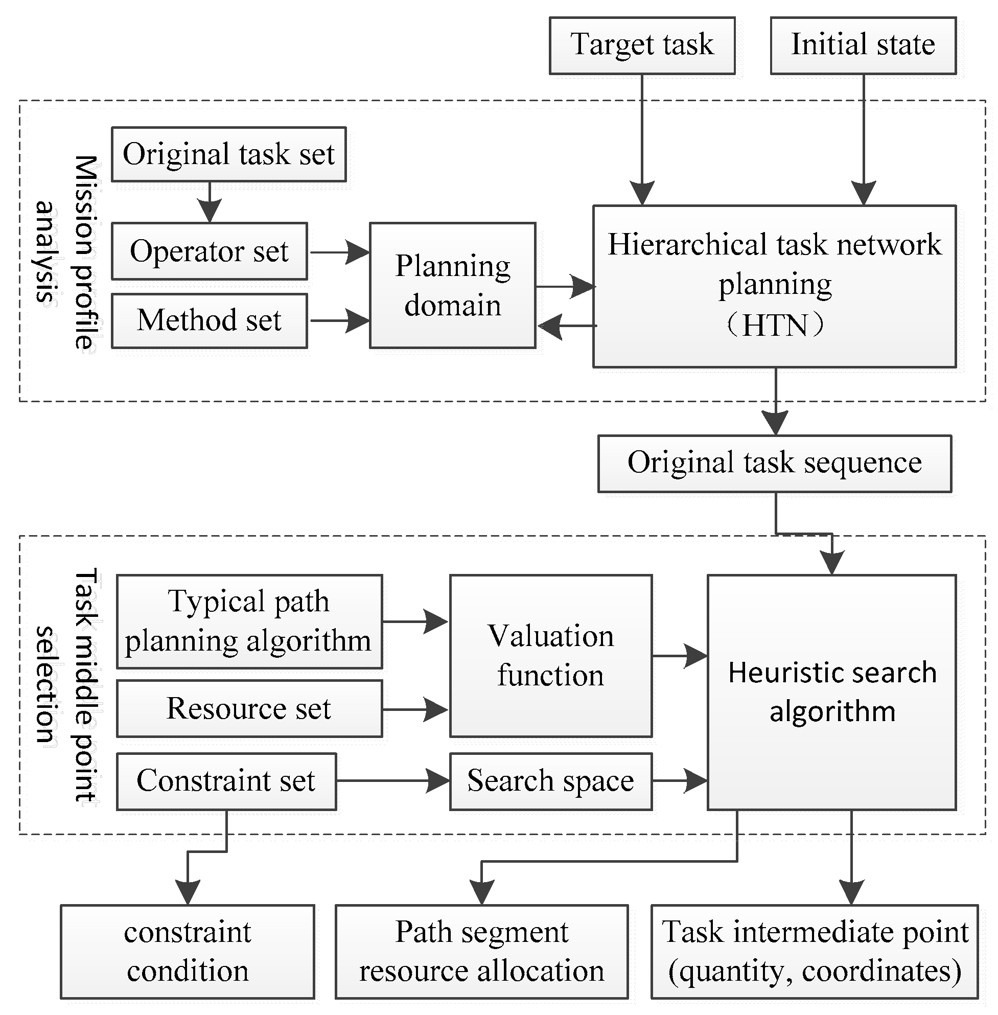
The control system of the space manipulator is divided into three levels: task planning, path planning and motion control. As the highest level of the manipulator control system, task planning is responsible for the reception, analysis and disassembly of task objectives and divides complex task objectives into a series of action sequences that the manipulator can directly plan and execute. Due to the diversity of ways for the manipulator to complete a task, task planning also involves the scheduling of various resources of the manipulator system, optimizes resource consumption in the whole task process and finally provides the planning results in the form of task intermediate point and resource allocation in each stage.
The task planning of the manipulator is divided into two stages that complete the planning process: first, accept the task objectives and decompose the complex tasks into simple original task combinations based on the working ability of the manipulator, to ensure the logical feasibility of the tasks; then, considering various constraints and optimization indicators, decompose each original task into multiple simple paths to ensure the feasibility of task execution. As shown in Figure 2, task planning is divided into two levels.
The first layer is responsible for task profile analysis. Logically, complex tasks are disassembled layer by layer to obtain the original task sequence that cannot be further subdivided.
The second layer is responsible for the selection of task intermediate points. Under the condition of optimizing and considering various available resources, iteratively search the task intermediate points for each original task in the original task sequence to obtain the number and coordinates of task intermediate points under constraints and with optimal resources.
4. Mission Profile Analysis of the Space Manipulator
The HTN planning method provides a general task planning scheme, but its operation process description is too general. It is necessary to design each component unit of the planner according to the specific application scenario of the space manipulator. In this chapter, a characterization method of the manipulator working environment is proposed, and an environmental state comparison method and a state transition formula are presented. The original task set and operator of the manipulator are defined. By instantiating the planning elements, the task profile analysis of the manipulator based on the HTN is realized.
4.1. Environmental State Characterization
The task profile analysis layer does not consider the size of the object, but only analyzes the logical relationship before and after the object is operated in the environment. Therefore, the object in the environment is abstracted into the operation interface vector. The end pose of the manipulator is consistent with the object interface vector to operate the object, and the movement of the object is abstracted as the change of the interface vector. Suppose there are one mechanical arm and objects in the environment, then the environmental state is represented by :
where is the end of the manipulator, and is the object; is the coordinate. For the manipulator, it refers to the end pose coordinate; for the object in the environment, it refers to the operation interface vector, which is generally defined in the capture position of the object; indicates whether the manipulator carries an object, . There are only two possibilities:
- (1)
- indicates that the manipulator is empty.
- (2)
- , indicates that there is only one item in for which ; for other items, gi = 0. It indicates that the manipulator carries the i-th object.
Define the state mask to assist the operation between the state matrices:
where .
4.1.1. State Condition Satisfaction Criterion
Before and after a task is executed, it is always necessary to judge whether the current environment state meets the preconditions or target states of the task. These target states usually only focus on some objects or some attributes of objects in the environment, and the values of other parameters are not constrained. Therefore, the state condition satisfaction criterion is given to judge whether some attributes of the environmental state meet the given requirements. For the current environment state , condition state and condition mask , if satisfied:
Then, the current environment state meets the condition state, and the masks on both sides of the state criterion formula must be consistent.
Define as the matrix and operate by the element: if the element in is 0, the corresponding element in is set to 0; if the element in is 1, the corresponding element in remains unchanged.
4.1.2. Status Change Operation
When an operator acts on the current environment, the current environment is transformed as follows:
where is the environment state after transformation, is the environment state before transformation, is the mask of the effect of the operator, is the inverse of , and is the state matrix of the effect of the operator.
4.2. Typical Original Tasks and Operators
According to the characteristics of the space manipulator and the analysis of on-orbit tasks, its original task set includes three basic original tasks: movement, capture and release. The corresponding operator contains the preconditions and completion status of the task.
- Movement
indicates that the end of the manipulator moves from the current point to point . The moving task only changes the position state of the manipulator itself and the position of the object grasped by the manipulator.
Conditions:
Completion:
where .
Since the manipulator can perform tasks in both unloaded and loaded states, the specific form of the operator of the mobile task is determined by the element in the last row of the first column at the initial state matrix of the manipulator.
- Capture
means that the robot arm captures an object numbered in the environment, and the position of object is .
Conditions:
Completion:
- Release
indicates that the manipulator releases the object numbered in the environment, and the end position of the manipulator is .
Conditions:
Completion:
4.3. Task Network Simplification of the Manipulator
Using the original tasks and operators defined above, a hierarchical task network was constructed according to the HTN theory. The core of HTN planning algorithm allows simplifying tasks and solving conflicts between tasks. Due to the serial execution of the manipulator, the planning problem is sequential, so an integrated task simplification and conflict handling strategy is proposed. The task network hierarchy of the planning problem is shown in Figure 3.
The specific flow of task profile analysis of the space manipulator is presented below, as shown in Figure 4.
- (1)
- Extracting tasks sequentially from the task network.
- (2)
- If the task is not the original task, find the corresponding one in the planning domain and replace the non-original task; The method of finding consists in comparing the effect mask of this task with that of each task in the set. If the set 1 item of the latter includes the former, can be used to simplify the task. Go to step 1.
- (3)
- Compare the current status with the completion status of the task. If the current status meets the task completion effect, it means that the task does not need to be executed, then delete the task from the task network.
- (4)
- If the current status meets the preconditions of the task, refresh the current status by using the operator of the task, go to step 1.
- (5)
- If the current status cannot meet the preconditions of the task, find a task that can meet the preconditions in the planning domain and add the task.
- (6)
- If the preconditions of the current task cannot be met, the result is planning failure.
5. Task Intermediate-Point Planning Modeling
Due to the complexity of the working environment of the manipulator, some original tasks given by the task profile analysis cannot be directly executed in the real environment constraints of the manipulator. For example, in the complex obstacle constraint environment, it is difficult for the manipulator with only the basic path planning algorithm (joint space planning or Cartesian space planning with fixed track) to directly complete a single mobile task, because there may be multiple obstacles between the start and the end points of the mobile task. Therefore, the second layer of manipulator task planning consists in planning several task intermediate points for a single original task, so that the manipulator can carry out a simple path planning between adjacent task intermediate points and complete the task through the combination of path segments.
5.1. Planner Interface
The task planning constraint set includes:
Joints: angle, angular velocity, angular acceleration;
End-effector: pose velocity and pose acceleration;
System: total time of subtask and environmental obstacles.
Resource sets include:
Joint distance, running time.
Decision vectors include:
Number and coordinates of the intermediate points.
The problem is described as follows:
In the feasible space without violating the constraint set, the decision vector is adjusted to optimize the resources in the resource set.
Set the interface of task planning problem as:
Input—starting and ending points of subtasks, constraint sets, typical path planning algorithms and weights of resources in the resource set;
Output—decision vector.
After planning, the output can be used to calculate the resource allocation of each stage (path segment).
5.2. Train of Thought Analysis
If the number of intermediate points is n, the time of the intermediate points is also n. Their coordinates are 6 dimensions * n.
Therefore, the decision vector (i.e., search space) is (6 + 2) n-dimensional. It can be seen that the dimension of the decision vector itself is also a variable, requiring decision. Therefore, the traditional intelligent optimization algorithm cannot be used to solve this problem.
A heuristic algorithm was adopted to avoid the problem of the number of intermediate points. When the algorithm is completed, the number of intermediate points is determined immediately. In each search step, it always moves towards the direction of optimal resources to ensure the optimal resources of the whole subtask.
The traditional heuristic algorithm based on the A* algorithm to search the middle point of the task in the subtask has defects in manipulator planning: A* works in the search environment with fixed topology. In the process of path generation, the current node relies on adjacent nodes to reach further nodes. When the node topology is determined (the search step is determined), even if it consumes less cost, the current node cannot directly reach the remote node [20].
This is not a big problem in the application fields of path length-dominated optimization objectives such as mobile robot planning, but this algorithm defect has a great impact on the algorithm results in manipulator path planning. Each path includes at least multiple motion stages such as acceleration, uniform speed, deceleration and so on. Direct and piecewise path planning are adopted at the same starting and ending points, and the cost is obviously different. To search the best task intermediate point in manipulator planning, the search algorithm needs to have the ability to connect non-adjacent nodes in the topology when generating the best path.
5.3. Specific Algorithm
A* algorithm valuation function
The cost is weighted summation after normalization of each resource concentration.
Improved ‘s computing strategy:
where is the actual cost from point to point , is the nominal parent node of the parent node of the current node, and is the parent node of the current node.
is defined as the nominal parent node, and the node with the lowest cost to in and is taken as ; typical path planning (such as straight-line planning) from the current point to the target point without considering constraints was adopted.
The algorithm flow is as follows in Figure 5.
Step 1, Search in the 6-dimensional workspace of the manipulator, position search and attitude search .
Step 2, Create two empty lists: OPEN list and CLOSE list.
Step 3, Starting from the point “start”, add it to the open list and calculate the of the point “start”. The nominal parent node of the starting point is itself.
Step 4, If the close list contains the target point “end”, go to step 9.
Step 5, Select the smallest node in the open list and place it into the close list.
Step 6, Find all nodes around the current node that are not in the close list and do not violate constraints .
Step 7, Calculate the of all nodes in , record the nominal parent node and add it to the open list.
Step 8, go to Step 4.
Step 9, Starting from the target point “end”, trace the whole path through the nominal parent node to obtain the task intermediate point.
6. Mission Planning Simulation
6.1. Test Conditions
Based on the above method, a task planning simulation of the manipulator under typical working conditions was carried out.
In the test environment, there are a manipulator M, an obstacle O and a moving target object U (here is the end of the manipulator). The constraints include interference avoidance of the external environment, joint angle limit (±270°), joint angular velocity limit (3°/s), etc. As shown in Figure 6, one end of the space manipulator was fixedly connected to a cabin. When its initial end coordinates were (2.774 m, 1.113 m, −4.502 m, −90°, 0°, 90°), the corresponding joint angle was (90°, −90°, −57°, 120°, 60°, −90°, 90°).
The planning domain of the task planner was configured as three original task operators and a “transfer” composite task.
When the manipulator m moved, it only had the ability of Cartesian space linear planning. The mission objective was designed to transfer the end U of the manipulator to the position C = (2.774 m, 2 m, 2 m, −90°, 0°, 90°); the corresponding joint angle was (110.01°, −95.43°, 35.43°, 77.72°, 12.84°, −76.48°, 74.14°).
6.2. Mobile Task Profile Analysis
The target task network is described as (achieve (trans (U, c))), and the coordinates of the end effector were calculated through the forward kinematics solution of the robot according to the initial configuration of the manipulator M.
B = [−0.48 m, −0.51 m, 0.18 m, −142.09°, −79.64°, −177.62°]
Therefore, the initial state of the environment was .
- (1)
- The target task network contained only one task and was not the original task. Therefore, we searched the corresponding Me in the planning domain and replaced trans (U, C) with Equation (13).
- (2)
- We traversed the task network again; n1 was the original task. We used the state criterion to compare the current state with the precondition of capture (U) operator: ; mask with status mismatch was .
- (3)
- To retrieve the planning domain, the move (v) operator can eliminate this state difference, so we added (n4: do [move (a)]) before n1 in the task network. The task network constraint became (n4, n1, n2, n3).
- (4)
- We retraversed the task network, and the initial state was transformed into by n4 operator, by n1 operator, , by n2 operator and by n3 operator.
So far, there was no conflict in the task network. The original task sequence given by the planner was: move (a) → capture (U) → move (c) → release (U). The manipulator end u was successfully transferred to C.
6.3. Simulation of Mobile Mission Midpoint Planning
According to the planner prosed in Section 5, we can add an intermediate point in the task and construct its planning modeling to achieve the task motion planning in Figure 7. After searching the path, the planned trajectory results are shown in Figure 8. We added one intermediate point with coordinates of (2.77 m, 3.11 m, 0.50 m, −85.37°, 29.79°, 76.78°) and corresponding joint angles of (93.74°, −92.40°, 31.21°, 67.04°, 54.97°, −86.49°, 70.01°). By adding intermediate points, the collision and interference during direct movement could be avoided, and the task path was automatically optimized.
When there was no task planning, the direct path planning between the starting point and the target point led to a collision between the manipulator and the cabin, as shown in Figure 9. The joint and end motion curves of the manipulator are shown in Figure 10 and met the constraints.
Other simulation cases: the task planning module followed the optimal path constraints and could add intermediate points to achieve the purpose of planning the optimal path that meets the constraints.
The initial joint angle of the manipulator was (−90°, 103°, 114°, 126°, 169°, −3°, 0°), the pose of the target point was (8.2 m, 3.47 m, 1.5 m, −167.88°, 24.207°, 43.487°). The position search step was 0.5 m. As shown in Figure 11, collision-free intermediate points were automatically added to the task planning results.
It can be seen from the simulation results that the motion goal of the manipulator was to achieve the accessibility of the given position and attitude. When considering the constraints, such as cabin interference, manipulator configuration and operation flexibility, the middle point of the motion process was added. On the basis of hierarchical task planning, the optimization of motion strategy was realized.
7. Conclusions
In this paper, the task planning algorithm of the manipulator was modeled according to the HTN theory. Through the profile analysis of the typical tasks of the space manipulator, the motion planning algorithm design of the task-oriented multi-constraint space manipulator was completed, and a typical application of the manipulator and cabin assembly was verified and simulated. On the basis of reasonable modeling and sufficient verification, aiming at the motion of the manipulator under multiple constraints, the target pose can be kept unchanged and the multi-stage trajectory can be automatically optimized to meet the task requirements.
By analyzing the simulation results, the following conclusions can be obtained:
- (1)
- When there is no task planning function, the direct movement of the manipulator will interfere, the manual adjustment will be inefficient, and the path will not be optimal.
- (2)
- The designed algorithm can solve many constraints; the planning efficiency is high, the path is the shortest, and the target pose is consistent.
This study provides the following innovations and contributions:
- (1)
- Combined with the characteristics of a space manipulator control system and various on-orbit service tasks, a two-tier framework of task planning for a complex on-orbit environment is proposed.
- (2)
- The idea of hierarchical task network is used to deal with the analysis and disassembly of complex tasks of a manipulator. Combined with the working characteristics of the space manipulator, state matrix, state mask and related algorithms are proposed, the operator expressions of three typical original tasks of space manipulator are presented, and the hierarchical task network planner for a space manipulator is realized.
- (3)
- Based on the improved A* algorithm, a task middle-point planning method is proposed, which enables the space manipulator to consider a variety of constraints at the same time in the complex obstacle environment, complete the task with the optimal resource allocation, reduce the operation loss of the mechanism and ensure the reliability of the mechanism.
The conflict between the simplifications of closed-world hypotheses in planning and the complex and changeable real-world situations has become a major problem in the field of robot research. At present, the working environment of robots tends to be complex and dynamic. Incomplete and uncertain information of the surrounding environment often leads to difficulties in the process of robot performing tasks. An effective and reasonable way to deal with this problem is to combine the method of artificial intelligence with robot control based on planning. This is an important research direction for this technology in the future.
Author Contributions
Conceptualization, C.L. and G.C.; methodology, C.L.; software, P.X.; validation, P.X. and D.P.; formal analysis, X.Z.; investigation, C.L. All authors have read and agreed to the published version of the manuscript.
Funding
This research received no external funding.
Institutional Review Board Statement
Not applicable.
Informed Consent Statement
Not applicable.
Data Availability Statement
Not applicable.
Conflicts of Interest
The authors declare no conflict of interest.
References
- Li, D.; Rao, W.; Hu, C. Research on Key Technologies of space station manipulator. Manned Spacefl. 2014, 20, 238–242. [Google Scholar]
- Dai, G. Research on Algorithm of Obstacle Avoidance Path Planning. Diploma Thesis, Huazhong University of Science and Technology, Wuhan, China, 2004. [Google Scholar]
- Baghli, F.Z.; El Bakkali, L.; Lakhal, Y. Optimization of arm manipulator trajectory planning in the presence of obstacles by ant colony algorithm. Procedia Eng. 2017, 181, 560–567. [Google Scholar] [CrossRef]
- Chen, J.; Zhao, M.; Zhang, H. Research on on-line real-time obstacle avoidance path planning of space manipulator. Control Eng. 2007, 14, 445–450. [Google Scholar]
- Zhang, J.; Zhao, Z.; Liu, H. Robot path planning based on artificial potential field method. J. Harbin Inst. Technol. 2006, 10, 1306–1309. [Google Scholar]
- Yao, J.F.; Lin, C.; Xie, X.B.; Wang, A.J.; Hung, C.C. Path planning for virtual human motion using improved A* star algorithm. In Proceedings of the Seventh International Conference on Information Technology, New Generations, IEEE, Las Vegas, NV, USA, 12–14 April 2010; pp. 1154–1158. [Google Scholar]
- Xu, W.-F.; Zhang, J.-T.; Yan, L.; Wang, Z.-Y. Parameterized inverse kinematics resolution method for a redundant space manipulator with link offset. J. Astronaut. 2015, 36, 33–39. [Google Scholar]
- Tian, Y. An Overall Configuration Planning Method of Continuum Hyper-Redundant Manipulators based on Improved Artificial Potential Field Method. In Proceedings of the IEEE International Conference on Robotics and Automation, ICRA, Xi’an, China, 30 May–5 June 2021; pp. 1436–1443. [Google Scholar]
- Wang, X.-H.; Li, S. A mission planning method for deep space explorer considering dynamic uncertainties. Chin. Space Sci. Technol. 2016, 36, 29. [Google Scholar]
- Mosteo, A.R.; Montano, L. Simulated Annealing for Multi-Robot Hierarchical Task Allocation with Flexible Constraints and Objective Functions. In Proceedings of the Workshop on Network Robot Systems: Toward Intelligent Robotic Systems Integrated with Environments, IROS, Beijing, China, 10 October 2006. [Google Scholar]
- Lozano-Pérez, T.; Kaelbling, L.P. A Constraint-Based Method for Solving Sequential Manipulation Planning Problems. In Proceedings of the 2014 IEEE/RSJ International Conference on Intelligent Robots and Systems, IEEE, Chicago, IL, USA, 14–18 September 2014; pp. 3684–3691. [Google Scholar]
- Zong, D.; Li, C.; Xia, S.; Wang, Z.Q. Hierarchical Task-Planning Method Based on Key-State for Virtual Human. J. Syst. Simul. 2013, 7, 18. [Google Scholar]
- Jia, Q.; Chen, G.; Sun, H.; Zheng, S. Obstacle avoidance path planning of space manipulator based on A* algorithm. J. Mech. Eng. 2010, 46, 109–115. [Google Scholar] [CrossRef]
- Haddad, M.; Khalil, W.; Lehtihet, H.E. Trajectory planning of unicycle mobile robots with a trapezoidal-velocity constraint. IEEE Trans. Robot. 2010, 26, 954–962. [Google Scholar] [CrossRef]
- Nejah, T.; Trevor, E.B.; Mohamed, A.E. Minimum time trajectory planning along specified tool path with consideration of cutting force constraint and feed drive dynamics. In Proceedings of the International Mechanical Engineering Congress & Exposition, New Orleans, LA, USA, 17–22 November 2002; ASME: New York, NY, USA, 2002; pp. 1–11. [Google Scholar]
- Zhang, B. Robot joint space trajectory planning based on multi constraints. J. Mech. Eng. 2011, 47. [Google Scholar] [CrossRef]
- Benton, J.; Do, M.; Kambhampati, S. Anytime heuristic search for partial satisfaction planning. Artif. Intell. 2009, 173, 562–592. [Google Scholar] [CrossRef] [Green Version]
- Tang, P.; Yang, Y.M. Study on algorithm A* of intelligent path planning based on method of representation environment with both quad tree and binary tree. Control Theory Appl. 2003, 20, 770–772. [Google Scholar]
- Zhang, H.; Cheng, Y. Path finding using Algorithm. Microcomput. Inf. 2007, 23, 238–239. [Google Scholar]
- Teng, R.; He, H.; Xiang, H.; Chen, B. Obstacle Avoidance Trajectory Planning of aerial vehicle based on heuristic path search. Robot 2013, 49, 311–316. [Google Scholar]
Figure 1.
The space manipulator structure.

Figure 2.
Task-planning system structure of the space manipulator.

Figure 3.
Task network hierarchy in task section analysis.

Figure 4.
Task network simplifying flow chart of the space manipulator.

Figure 5.
Task planning for intermediate-point flow chart.

Figure 6.
Test scenario.

Figure 7.
Initial state of task planning.

Figure 8.
Movement trajectory with task planning. (a) Starting point. (b) Intermediate point. (c) Target point.
Figure 8.
Movement trajectory with task planning. (a) Starting point. (b) Intermediate point. (c) Target point.

Figure 9.
Movement trajectory without task planning.

Figure 10.
Position and velocity curves of joints and end-effector.


Figure 11.
Position and velocity curve of joints and end-effector.

Publisher’s Note: MDPI stays neutral with regard to jurisdictional claims in published maps and institutional affiliations. |
© 2022 by the authors. Licensee MDPI, Basel, Switzerland. This article is an open access article distributed under the terms and conditions of the Creative Commons Attribution (CC BY) license (https://creativecommons.org/licenses/by/4.0/).
Share and Cite
MDPI and ACS Style
Liang, C.; Pan, D.; Chen, G.; Xin, P.; Zhang, X. Task-Oriented Motion Planning of a Space Manipulator under Multiple Constraints. Appl. Sci. 2022, 12, 5369. https://0-doi-org.brum.beds.ac.uk/10.3390/app12115369
AMA Style
Liang C, Pan D, Chen G, Xin P, Zhang X. Task-Oriented Motion Planning of a Space Manipulator under Multiple Constraints. Applied Sciences. 2022; 12(11):5369. https://0-doi-org.brum.beds.ac.uk/10.3390/app12115369
Chicago/Turabian StyleLiang, Changchun, Dong Pan, Gang Chen, Pengfei Xin, and Xiaodong Zhang. 2022. "Task-Oriented Motion Planning of a Space Manipulator under Multiple Constraints" Applied Sciences 12, no. 11: 5369. https://0-doi-org.brum.beds.ac.uk/10.3390/app12115369
Note that from the first issue of 2016, this journal uses article numbers instead of page numbers. See further details here.